Abstract
This paper presents the design and performance evaluation of a compact four-element coplanar waveguide (CPW)-fed antenna array operating in the 3.3–3.6 GHz frequency band. The proposed antenna is tailored for sub-6 GHz 5G New Radio (NR) applications, specifically aligning with the n77/n78 bands widely adopted for mid-band 5G deployment. The CPW feeding technique enables low-profile integration and ease of fabrication, while the multi-element configuration supports enhanced gain and spatial diversity. Both simulated and measured results demonstrate good impedance matching (|S11| < −10 dB), stable radiation patterns, and inter-element isolation suitable for MIMO operation. The design offers a promising solution for compact 5G antenna systems and can be extended to future wireless communication platforms requiring high efficiency and compact form factors.
1. Introduction
The sub-6 GHz spectrum has emerged as a cornerstone of 5G communications, particularly in the 3.3–3.8 GHz range, where it offers a favorable trade-off between coverage and capacity [1]. This frequency range is extensively allocated across regions for 5G New Radio (NR) bands n77 and n78, making it a critical focus area for antenna researchers [2,3,4]. Consequently, compact, high-performance MIMO antennas with low mutual coupling and wide impedance bandwidth are essential to meet the requirements of current and emerging wireless platforms [5].
Among the various feeding techniques, coplanar waveguide (CPW) feeding has gained attention due to its planar structure, low radiation loss, broad bandwidth potential, and compatibility with integrated circuits [6]. Building on these advantages, ref. [6] presents a 4-element MIMO antenna designed for 5G NR N77/N78, Wi-Fi 6/6E, and X-band satellite communication. However, the CPW-fed elements lack a connected ground plane, which undermines the accuracy of the MIMO performance claims. Ground continuity is essential to properly model mutual coupling, current return paths, and realistic isolation and ECC values. Without it, the simulated results may be overly optimistic and not representative of practical performance. Numerous recent studies have investigated CPW-fed antennas for wireless applications [7,8,9]. For instance, ref. [8] presents a compact ultra-wideband CPW-fed MIMO antenna covering 3–11 GHz, featuring four orthogonally placed jug-shaped elements for improved isolation and polarization diversity.
To enhance spatial diversity, various dual- and multi-port CPW-fed MIMO designs have been investigated. In [10], to enhance spatial diversity, a λ/2 spacing was maintained between all CPW-fed elements, improving isolation and overall MIMO performance. In [11], the design enhances isolation using a structured two-step method based on odd-mode (OM) and even-mode (EM) impedance matching. First, the OM input impedance is optimized by adjusting the spacing between antenna elements to improve decoupling. Then, the EM input impedance is matched by introducing a coupled, nondispersive TEM transmission line, enabling wideband decoupling without significantly increasing the feed-point spacing. In [12], a T-shaped neutralization line acts as an artificial coupling path that destructively interferes with the natural mutual coupling between the two CPW-fed radiators. This improves isolation, bandwidth, and diversity performance, making the antenna suitable for UWB MIMO applications where space is limited but high-performance isolation is required.
Alternative strategies include orthogonal element placement with parasitic isolation structures, as demonstrated in [13]. The incorporation of corner-trimmed and spiral-inspired parasitic structures enhances isolation in MIMO antennas by generating out-of-phase currents that oppose mutual coupling. In [14], the study employed an H-shaped EBG structure between two closely spaced CPW-fed elements. The two-unit cell EBG effectively suppresses mutual coupling, achieving over 20 dB isolation across the band and up to 37 dB maximum throughout the operating frequency range. Researchers incorporated complementary split ring resonators (CSRR) into the CPW-fed antenna design, which alters the surface current distribution and suppresses coupling paths between elements. As a result, the 4 × 4 MIMO configuration in [15] achieves nearly 20 dB isolation between antenna elements without requiring additional decoupling structures.
These recent studies demonstrate that while significant progress has been made in sub-6 GHz CPW-fed MIMO antennas, there remains a need for designs that simultaneously achieve compactness, high isolation, low ECC, and ease of fabrication. The proposed work addresses this gap by presenting a compact (110 mm × 45 mm), four-element CPW-fed MIMO antenna operating from 3.3 to 3.6 GHz. It achieves measured isolation better than −25 dB, ECC < 0.1, and diversity gain approaching 10 dB, without the need for EBGs, Defected Ground Structure (DGS), or complex decoupling networks. The high isolation performance is further enhanced by incorporating a simple T-shaped isolation structure placed between adjacent elements.
2. Antenna Design
2.1. Single Element Configuration
Figure 1 illustrates the evolution of a single antenna element design intended for integration in MIMO applications, both printed on a 1.6 mm thick FR4 substrate with a relative permittivity of 4.3.
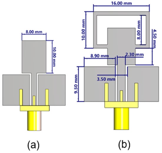
Figure 1.
Evolution of the single antenna element design intended for MIMO applications, printed on a 1.6 mm thick FR4 substrate (εr = 4.3). (a) Initial monopole design with a simple rectangular radiator. (b) Modified design incorporating a rectangular parasitic rectangle.
In Figure 1a, the antenna consists of a simple monopole structure with a rectangular radiating patch measuring 10.00 mm in height and 8.00 mm in width. The antenna is fed using a coplanar waveguide (CPW) configuration, with the feedline and ground conductors printed on the same side of the substrate. The lower part of the structure shows partial ground planes symmetrically placed on both sides of the feedline. This basic design serves as the initial reference model, offering limited bandwidth and isolation characteristics.
Figure 1b shows the evolved design, incorporating significant modifications to enhance bandwidth and isolation for MIMO suitability. A rectangular ring-shaped parasitic structure is introduced at the top of the monopole, measuring 16.00 mm in width and 10.00 mm in height, with an inner cutout of 8.00 mm by 14 mm. This parasitic element is loaded around the central radiator to introduce additional resonances and improve impedance matching. The base structure remains CPW-fed, with the same 2.30 mm wide feedline flanked by narrow ground strips separated by gaps of 0.6 mm.
The S11 plot in Figure 2 compares the reflection coefficient magnitude (in dB) for the antenna structures shown in Figure 1a,b. The structure in Figure 1a exhibits poor impedance matching across the entire 2.0–4.0 GHz range, with an S11 value consistently above −5 dB, indicating high reflection and limited resonance behavior. This implies inefficient radiation and narrowband performance.
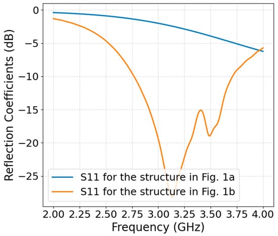
Figure 2.
Comparison of the simulated reflection coefficients (S11) for the antenna structures in Figure 1a,b.
In contrast, the structure in Figure 1b demonstrates significantly improved impedance matching, with multiple resonant dips below −10 dB, particularly around 3.2 GHz and 3.6 GHz, where the S11 drops below −25 dB and −15 dB, respectively. This suggests that the introduction of the rectangular parasitic ring in Figure 1b introduces multiple resonant modes, broadens the bandwidth, and greatly enhances return loss, making the design more suitable for wideband or multi-band MIMO applications.
2.2. MIMO Antenna Configuration
The illustrated MIMO antenna structure in Figure 3 is designed using the evolved single-element structure previously discussed in Figure 1b. The array is printed on a 45.00 mm × 110.00 mm rectangular FR4 substrate with a thickness of 1.6 mm and a relative permittivity of 4.3. Each antenna element features a rectangular parasitic ring surrounding a central monopole fed via a coplanar waveguide (CPW) configuration, with the ground and feedline printed on the same side of the substrate.
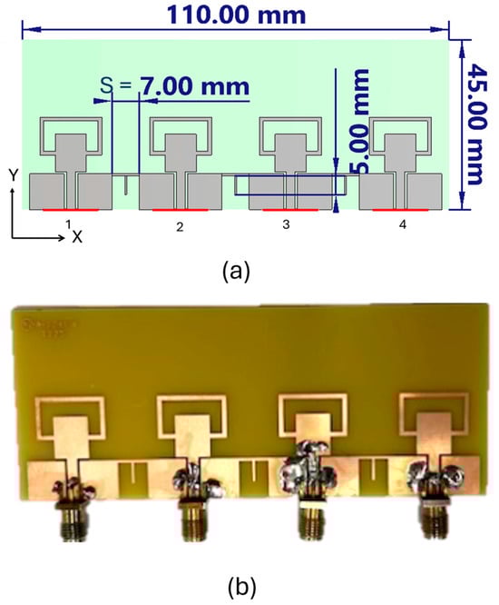
Figure 3.
(a) Proposed MIMO antenna; (b) Fabricated MIMO antenna.
The elements are evenly spaced with a horizontal spacing of 7.00 mm. Between adjacent elements, a T-shaped decoupling structure is inserted, measuring 7.00 mm in width and 5.00 mm in height, aimed at suppressing mutual coupling and improving isolation across the operating band. When referenced to an operating frequency of 3.5 GHz, the free-space wavelength (λ) is approximately 85.7 mm. Thus, the inter-element spacing corresponds to approximately 0.082λ, and the decoupling structure dimensions translate to 0.082λ × 0.058λ. This compact spacing, combined with the decoupling structures, enables enhanced isolation and is well-suited for sub-6 GHz MIMO applications where antenna miniaturization and performance optimization are critical.
Figure 4 illustrates the measured and simulated reflection coefficients (S11, S44, S22, and S33) of the proposed MIMO antenna across the 2.5–4.0 GHz frequency range. The results highlight the symmetrical nature of the antenna design, as evidenced by the close agreement between S11 and S44, as well as between S22 and S33. This symmetry confirms that the antenna elements are identically designed and equally spaced, ensuring consistent input matching performance across ports. The measured reflection coefficients for both S11/S44 and S22/S33 achieve deep notches around 3.4 GHz, with minimum values reaching below −25 dB and −30 dB, respectively. These values indicate excellent impedance matching. The measured −10 dB impedance bandwidth spans from approximately 3.3 GHz to 3.65 GHz, providing a 350 MHz bandwidth, which is well-suited for sub-6 GHz 5G applications, respectively.
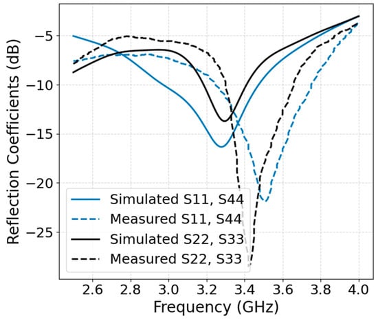
Figure 4.
Magnitude of reflection coefficients in dB.
Figure 5 presents the simulated and measured transmission coefficients of the proposed four-port MIMO antenna, highlighting the mutual coupling behavior between different antenna elements. The results confirm that the antenna achieves strong isolation, particularly around the center frequency of 3.4 GHz. Most transmission coefficients—including S21, S34, S31, and S41—maintain values below −10 dB from approximately 3.3 to 3.6 GHz, which meets the isolation requirements for effective MIMO performance. The S23 parameter exhibits the highest isolation, with similar values reaching below −35 dB and measured values around −25 dB, centered at 3.4 GHz. However, at 3.2 GHz, S23 remains above −10 dB, indicating that optimal decoupling occurs specifically around 3.4 GHz. These results validate the antenna’s capability to minimize mutual coupling within the intended operational band, supporting its suitability for sub-6 GHz MIMO applications.
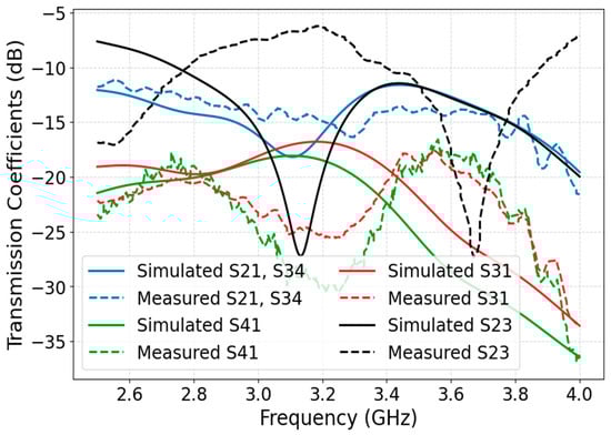
Figure 5.
Magnitude of transmission coefficients in dB.
3. Radiation Performance
3.1. Far-Field Analysis
This section presents a detailed investigation of the far-field radiation pattern and normalized peak gain of the proposed MIMO antennas. The radiation characteristics of ports 1 and 2 are analyzed in the relevant planes. Figure 6 and Figure 7 illustrate the 2D normalized radiation patterns of the proposed 4-element MIMO antenna at 3.5 GHz, measured using Port 1 and Port 2, respectively. Given the symmetry of the antenna structure in the X–Y plane, the analysis is limited to these two representative ports.
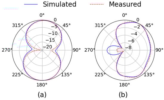
Figure 6.
Two-dimensional normalized radiation pattern using port 1 at 3.5 GHz: (a) xz-plane, (b) yz-plane.
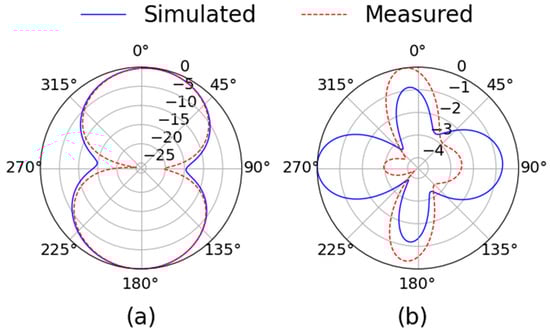
Figure 7.
Two-dimensional normalized radiation pattern using port 2 at 3.5 GHz: (a) xz-plane, (b) yz-plane.
For Port 1, shown in Figure 6, the radiation pattern in the XZ-plane (Figure 6a) displays a nearly bidirectional response with well-formed main lobes radiating along the ±Z-axis. This indicates efficient broadside radiation, which is favorable for many wireless communication scenarios. In the YZ-plane (Figure 6b), the pattern shows a slightly tilted directional lobe. The simulated and measured results align closely, confirming reliable radiation behavior and good fabrication accuracy.
Port 2, presented in Figure 7, exhibits similar characteristics. The XZ-plane radiation pattern (Figure 7a) maintains the bidirectional nature observed in Port 1, with symmetrical main lobes and low side lobe levels. In the YZ-plane (Figure 7b), the radiation pattern becomes more complex, showing multiple lobes. Despite this complexity, the measured and simulated patterns are in good agreement, underscoring the design’s repeatability and robustness.
Overall, the radiation characteristics of both ports demonstrate strong consistency, stable far-field patterns, and effective spatial coverage. These attributes make the antenna well-suited for MIMO applications, where pattern diversity and inter-element isolation are essential for performance.
3.2. Surface Current Density
Figure 8 reports surface current density in A/m. When the array uses the T-shaped decoupling (Figure 8a, Port 1 excited), the peak current on the driven element is ~0.03–0.04 A/m, while the coupled current on the nearest adjacent element remains below ~0.007–0.010 A/m. This corresponds to a coupled/driven current ratio of 0.18–0.33 (≈9–15 dB lower). In the baseline without decoupling (Figure 8b, Port 2 excited), adjacent element peaks rise to ~0.015–0.020 A/m for a ratio of 0.38–0.55 (≈5–8 dB lower).
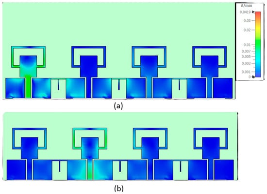
Figure 8.
Surface current density (A/mm) at 3.5 GHz: (a) port 1 is excited, (b) port 2 is excited.
4. MIMO Performance Analysis
The Envelope Correlation Coefficient (ECC) is a crucial metric used to evaluate the performance of multiple-input multiple-output (MIMO) antenna systems. It quantifies the level of similarity or coupling between the radiation patterns of antenna elements. Ideally, in a MIMO system, the antenna elements should be uncorrelated to maximize diversity gain and system capacity. A lower ECC value indicates better isolation and diversity performance, with values below 0.5 typically considered acceptable for practical systems. ECC can be calculated using either far-field radiation patterns or the following formula for a two-port network [16]:
where
- and are the θ- and ϕ-components of the antenna’s far-field radiation pattern.
- and are the angular power density functions of the incoming wave.
- XPR is the cross-polarization ratio, typically taken in isotropic environments.
Figure 9 presents the ECC performance of the proposed antenna across a frequency range of 3.0 to 4.0 GHz, with a focus on the operating band between 3.3 and 3.6 GHz (highlighted in gray). The ECC values for all antenna element pairs (1–2, 2–3, 1–3, and 1–4) remain well below 0.5 within the operating band, indicating strong MIMO performance. The highest observed ECC values are for pairs 1–2 and 2–3, peaking around 0.3, while pairs 1–3 and 1–4 consistently exhibit values below 0.05, reflecting excellent isolation and pattern diversity.
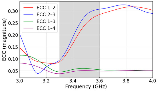
Figure 9.
Envelope correlation coefficients of the proposed antenna.
Diversity Gain (DG) is another critical metric in multiple-input multiple-output (MIMO) antenna systems that quantifies the improvement in signal reliability due to the use of multiple uncorrelated antennas. It reflects how effectively a system can mitigate fading effects by exploiting spatial diversity. In an ideal two-antenna system with no correlation, the maximum achievable diversity gain is 10 dB. The diversity gain is often computed using the Envelope Correlation Coefficient (ECC) via the following relation [17]:
Figure 10 illustrates the Diversity Gain (DG) across a frequency range of 3.0 to 4.0 GHz for different antenna element pairs (1–2, 2–3, 1–3, and 1–4). The target operating band (3.3–3.7 GHz) is shaded in gray. Within this band, the diversity gain for most antenna pairs remains close to the ideal value of 10 dB, particularly for pairs 1–3 and 1–4, which show minimal variation and stay nearly flat, reflecting excellent performance. In contrast, DG values for pairs 1–2 and 2–3 exhibit a slight dip within the band, decreasing to around 9.5 dB, which is still considered acceptable for practical MIMO systems.
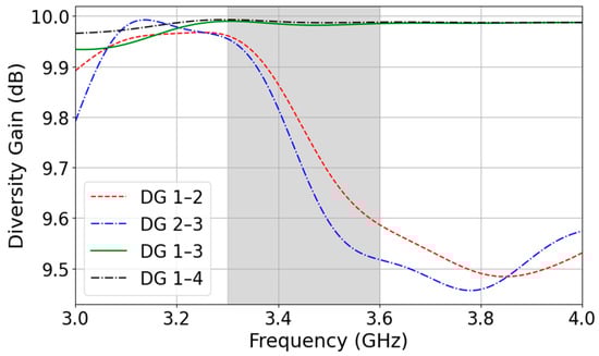
Figure 10.
Diversity gains of the proposed antenna.
Mean Effective Gain (MEG) is an important parameter in MIMO systems that quantifies the average power received by an antenna element in a multipath-rich environment. MEG helps evaluate how efficiently each antenna element receives power when waves arrive from multiple directions with random polarization. In the absence of far-field radiation data, MEG can be estimated using S-parameters, which are readily available from simulation or measurement.
The MEG for port i can be approximated by the following formula [18]:
where
- MEGi is the mean effective gain of port i.
- Sij is the S-parameter representing the coupling or reflection from port j to port i.
- N is the total number of antenna elements.
- The factor 0.5 accounts for the uniform angular power distribution in both polarization components.
This formula assumes isotropic or Rayleigh fading conditions, equal power distribution, and symmetry across the array.
To maintain balanced performance in MIMO systems, the MEG difference between any two ports should not exceed 3 dB:
|MEGi − MEGj| ≤ 3 dB
Figure 11a shows the MEG values for ports 1 to 4 of the proposed MIMO antenna across a frequency range of 3.0–4.0 GHz. In the 3.3–3.6 GHz band, Ports 1 and 4 maintain MEG values close to −3.5 dB, while Ports 2 and 3 exhibit slightly lower values that go to −5.3 dB. The maximum imbalance is therefore less than 2 dB, which is well within the accepted tolerance.
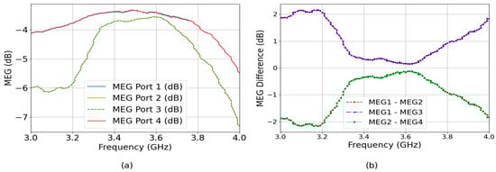
Figure 11.
(a) Mean effective gain of the proposed MIMO antenna, (b) the difference between MEG values.
Figure 11b presents the MEG differences between ports, which assess power imbalance among antenna elements. For optimal performance, MEG differences between any two ports should be less than 3 dB. The curves for MEG1–MEG2, MEG1–MEG3, and MEG2–MEG4 mostly stay within ±2 dB across the band, which confirms that the antenna ports exhibit balanced power reception and maintain good multipath efficiency.
In the operating bandwidth of 3.4–3.6 GHz, the radiation efficiency of the 4-element MIMO antenna remains high, with values between approximately 78% and 84% for both simulated and measured results, as shown in Figure 12. This indicates that the antenna operates with minimal loss, ensuring that most of the input power is effectively radiated. The strong agreement between measured and simulated efficiencies further validates the accuracy of the design and confirms that fabrication and measurement variations have only a small impact on performance. Such consistently high efficiency across the band demonstrates the antenna’s reliability and suitability for sub-6 GHz MIMO applications.
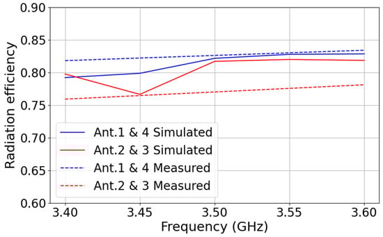
Figure 12.
Measured and simulated radiation efficiency.
While the proposed four-element configuration effectively demonstrates the compactness, bandwidth enhancement, and isolation characteristics of the design, it can also be scaled to meet the requirements of practical 5G antenna systems that typically employ a larger number of elements. The modular geometry and decoupling techniques presented in this work allow straightforward extension to 8-, 16-, or even higher-order arrays, either in linear or planar arrangements, without significant degradation in performance. In larger arrays, the use of replicated modules enables higher gain and improved beamforming capability while maintaining compact size and low mutual coupling. Although feed network complexity and coupling scenarios naturally increase with array size, the underlying decoupling approach remains applicable and scalable, making the design a promising candidate for adaptation in realistic 5G applications.
Table 1 shows a comparison between the proposed antenna and recent research. Compared with prior works, the proposed 4-element MIMO antenna achieves a compact size of 110 × 45 mm2, smaller than several multi-element designs [2,19,20], while directly targeting the practical 3.3–3.6 GHz sub-6 GHz 5G band. Although its ECC (0.3) and isolation (-10 dB) are weaker than most references, this trade-off reflects the balance between compactness and element count, as higher isolation values are generally achieved either with larger structures or simpler two-element systems. Overall, the design offers a practical and space-efficient solution with room for future improvements in coupling reduction.

Table 1.
Comparison of the proposed MIMO antenna with prior work.
5. Conclusions
This work presents a compact, high-performance CPW-fed four-element MIMO antenna array designed for sub-6 GHz 5G applications, specifically targeting the n77/n78 bands. A key innovation of this design lies in the integration of a simple yet effective T-shaped neutralization line between antenna elements, which significantly enhances isolation without increasing design complexity or requiring additional decoupling structures like EBGs or DGS. The antenna achieves excellent isolation better than −10 dB, envelope correlation coefficients (ECC) below 0.5, and diversity gains close to the theoretical maximum of 10 dB. Moreover, the use of CPW feeding not only enables low-profile integration and ease of fabrication but also supports wideband impedance matching and robust MIMO performance, as evidenced by both simulation and measurement results.
Beyond isolation, the antenna exhibits stable far-field radiation patterns, high gain, and good port-to-port power balance across the 3.3–3.6 GHz operating band. The inclusion of parasitic rectangular ring structures around each radiator broadens the bandwidth and improves matching, while maintaining a compact footprint (110 mm × 45 mm). The surface current and MEG analysis further validate the antenna’s ability to suppress mutual coupling and achieve well-balanced spatial diversity. These attributes make the proposed design an excellent candidate for 5G NR applications, with the potential for scalability and adaptation to other high-efficiency, space-constrained wireless platforms.
Funding
This research was funded by the Office of Research and Sponsored Projects (ORSP) at Texas A&M University–Texarkana (TAMUT).
Institutional Review Board Statement
Not applicable.
Informed Consent Statement
Not applicable.
Data Availability Statement
All data generated and analyzed in this study are presented in the article.
Conflicts of Interest
The author declares no conflicts of interest.
References
- Pons, M.; Valenzuela, E.; Rodríguez, B.; Nolazco-Flores, J.A.; Del-Valle-Soto, C. Utilization of 5G Technologies in IoT Applications: Current Limitations by Interference and Network Optimization Difficulties—A Review. Sensors 2023, 23, 3876. [Google Scholar] [CrossRef]
- Wang, Z.; You, W.; Yang, M.; Nie, W.; Mu, W. Design of MIMO Antenna with Double L-Shaped Structure for 5G NR. Symmetry 2023, 15, 579. [Google Scholar] [CrossRef]
- Srinubabu, M.; Venkata Rajasekhar, N. A Compact and Efficiently Designed Two-Port MIMO Antenna for N78/48 5G Applications. Heliyon 2024, 10, e28981. [Google Scholar] [CrossRef] [PubMed]
- Wei, X.; Lu, J.; Miao, Y.; Huang, J.; Chen, Z.; Liu, G. High Isolation MIMO Antenna System for 5G N77/N78/N79 Bands. Micromachines 2024, 15, 721. [Google Scholar] [CrossRef] [PubMed]
- Sharma, P.; Tiwari, R.N.; Singh, P.; Kumar, P.; Kanaujia, B.K. MIMO Antennas: Design Approaches, Techniques and Applications. Sensors 2022, 22, 7813. [Google Scholar] [CrossRef]
- Du, C.; Zhang, F.; Li, R. Design of Tri-Band Flexible CPW 4-Port Slot MIMO Antenna for Conformal 5G, WIFI 6/6E and X-Band Applications. Eng. Sci. Technol. Int. J. 2025, 62, 101937. [Google Scholar] [CrossRef]
- Rai, J.K.; Yadav, S.; Ranjan, P.; Chowdhury, R.; Das, G. A Compact Quad Element MIMO CPW Fed Ultra-wideband Antenna for Future Wireless Communication Using Machine Learning Optimization. Int. J. Commun. Syst. 2025, 38, e5995. [Google Scholar] [CrossRef]
- Ahmad, S.; Khan, S.; Manzoor, B.; Soruri, M.; Alibakhshikenari, M.; Dalarsson, M.; Falcone, F. A Compact CPW-Fed Ultra-Wideband Multi-Input-Multi-Output (MIMO) Antenna for Wireless Communication Networks. IEEE Access 2022, 10, 25278–25289. [Google Scholar] [CrossRef]
- Halilu Jabire, A.; Alkhoori, H.M.; Ghaffar, A.; Faouri, Y.S.; Dahir, A.; Hussein, M.I. Frequency and Pattern Reconfigurable CPW-Fed MIMO Antenna with Multiband and Wideband Characteristics. IEEE Access 2024, 12, 120165–120180. [Google Scholar] [CrossRef]
- Patel, A.; Desai, A.; Elfergani, I.; Vala, A.; Mewada, H.; Mahant, K.; Patel, S.; Zebiri, C.; Rodriguez, J.; Ali, E. UWB CPW Fed 4-Port Connected Ground MIMO Antenna for Sub-Millimeter-Wave 5G Applications. Alex. Eng. J. 2022, 61, 6645–6658. [Google Scholar] [CrossRef]
- Zhou, Z.; Ge, Y.; Yuan, J.; Xu, Z.; Chen, Z.D. Wideband MIMO Antennas With Enhanced Isolation Using Coupled CPW Transmission Lines. IEEE Trans. Antennas Propag. 2023, 71, 1414–1423. [Google Scholar] [CrossRef]
- Dkiouak, A.; El Ouahabi, M.; Chakkor, S.; Baghouri, M.; Zakriti, A.; Lagmich, Y. High Performance UWB MIMO Antenna by Using Neutralization Line Technique. Prog. Electromagn. Res. C 2023, 131, 185–195. [Google Scholar] [CrossRef]
- Ravi, K.C.; Kumar, J. Miniaturized Parasitic Loaded High-Isolation MIMO Antenna for 5G Applications. Sensors 2022, 22, 7283. [Google Scholar] [CrossRef] [PubMed]
- Kumar, A.; De, A.; Jain, R.K. Novel H-Shaped EBG in E-Plane for Isolation Enhancement of Compact CPW-Fed Two-Port UWB MIMO Antenna. IETE J. Res. 2023, 69, 5986–5992. [Google Scholar] [CrossRef]
- Rajesh Kumar, D.; Sangeetha, T.; Sujanth Narayan, K.G.; Venkat Babu, G.; Prithivirajan, V.; Manikandan, M.S.K. A Miniaturized CPW-Fed CSRR-Loaded Quad-Port MIMO Antenna for 5.5/6.5 GHz Wireless Applications. Int. J. Microw. Wirel. Technol. 2024, 16, 167–176. [Google Scholar] [CrossRef]
- Stein, S. On Cross Coupling in Multiple-Beam Antennas. IEEE Trans. Antennas Propag. 1962, 10, 548–557. [Google Scholar] [CrossRef]
- Jamal, M.Y.; Li, M.; Yeung, K.L. Isolation Enhancement of Closely Packed Dual Circularly Polarized MIMO Antenna Using Hybrid Technique. IEEE Access 2020, 8, 11241–11247. [Google Scholar] [CrossRef]
- Rafique, U.; Agarwal, S.; Nauman, N.; Khalil, H.; Ullah, K. INSET-FED PLANAR ANTENNA ARRAY FOR DUAL-BAND 5G MIMO APPLICATIONS. Prog. Electromagn. Res. C 2021, 112, 83–98. [Google Scholar] [CrossRef]
- Ahmad, U.; Ullah, S.; Rafique, U.; Choi, D.-Y.; Ullah, R.; Kamal, B.; Ahmad, A. MIMO Antenna System With Pattern Diversity for Sub-6 GHz Mobile Phone Applications. IEEE Access 2021, 9, 149240–149249. [Google Scholar] [CrossRef]
- Sim, C.-Y.-D.; Dhasarathan, V.; Tran, T.K.; Kulkarni, J.; Garner, B.A.; Li, Y. Mutual Coupling Reduction in Dual-Band MIMO Antenna Using Parasitic Dollar-Shaped Structure for Modern Wireless Communication. IEEE Access 2023, 11, 5617–5628. [Google Scholar] [CrossRef]
- Dai, X.W.; Hu, W.H.; Hong, H.; Luo, G.Q. High Isolation MIMO Antenna Designed with Tightly Coupled Microstrip Patch Pairs. AEU-Int. J. Electron. Commun. 2024, 177, 155169. [Google Scholar] [CrossRef]
- Latane, P.; Patil, D.; Kale, V.; Chopade, P.; Kota, P. 4-Port MIMO Antenna Diversity Analysis for 5G Applications. Int. J. Intell. Syst. Appl. Eng. 2023, 11, 385–396. [Google Scholar]
- Zhou, J.; Yang, M. Design of Six Port Antenna with Frequency Diversity and Diverse Radiation Pattern. IEEE Access 2022, 10, 65962–65970. [Google Scholar] [CrossRef]
- Khan, I.; Wu, Q.; Ullah, I.; Rahman, S.U.; Ullah, H.; Zhang, K. Designed Circularly Polarized Two-Port Microstrip MIMO Antenna for WLAN Applications. Appl. Sci. 2022, 12, 1068. [Google Scholar] [CrossRef]
- Chung, M.-A.; Hsieh, M.-C.; Hsu, C.-C.; Yang, C.-W.; Lin, C.-W. A Novel 2×2 MIMO Antenna with Microstrip Line Structure for Sub-6 GHz and WiFi 6E Applications. In Proceedings of the 2024 IEEE International Workshop on Electromagnetics: Applications and Student Innovation Competition (iWEM), Taoyuan, China, 10 July 2024; IEEE: New York, NY, USA, 2024; pp. 1–2. [Google Scholar]
Disclaimer/Publisher’s Note: The statements, opinions and data contained in all publications are solely those of the individual author(s) and contributor(s) and not of MDPI and/or the editor(s). MDPI and/or the editor(s) disclaim responsibility for any injury to people or property resulting from any ideas, methods, instructions or products referred to in the content. |
© 2025 by the author. Licensee MDPI, Basel, Switzerland. This article is an open access article distributed under the terms and conditions of the Creative Commons Attribution (CC BY) license (https://creativecommons.org/licenses/by/4.0/).