Abstract
Bipolar DC microgrids gain significant attention for their flexible structure, high power supply reliability, and strong compatibility with distributed power sources. However, inter-pole voltage imbalance undermines system operational stability. An isolated bipolar bidirectional three-port converter with voltage self-balancing capability is proposed in this paper, which can serve as the interface between the energy storage system and bipolar bus while achieving automatic voltage balance between poles. Unlike traditional bidirectional grid-connected voltage balancers (VBs), the proposed converter requires no additional voltage monitoring or complex control systems. The operating modes, soft-switching boundary conditions, and inter-pole voltage self-balancing mechanism are elaborated. A 1 kW experimental prototype has been built to validate the theoretical analysis of the proposed converter.
1. Introduction
Bipolar DC microgrid has become a research hotspot because its bus architecture is convenient for distributed energy, energy storage devices, and DC load access, and has the technical advantages of flexible voltage level, low transmission loss, and high power quality [1,2]. Stable bus voltage and balanced inter-pole voltage are key guarantees for the stable and reliable operation of bipolar DC microgrids [3,4,5]. During islanded operation, the bus voltage stability is maintained by the converter connected to the energy storage system, while the inter-pole voltage balance relies on a dedicated voltage balancer [6,7,8,9]. The topologies of common voltage balancers can be divided into non-isolated and isolated types. The derivation of non-isolated VBs is mostly based on basic bidirectional topologies [10,11,12,13] and three-level topologies [14,15,16,17], while typical isolated VBs are mainly realized through dual-active-bridge (DAB) topologies [18,19,20,21,22,23,24]. In the research of isolated VB topologies, a VB topology based on three-level DAB converter is proposed in [19,20], which achieves output voltage balancing by controlling the charging/discharging processes of voltage divider capacitors through modulation of switching sequences in the three-level DAB converter. Another isolated VB topology is proposed in [20,21,22,23], which connects two triple-active-bridge (TAB) series at the output side. This converter employs two independent control variables to regulate the bipolar output power, thereby achieving output voltage balancing. However, the inter-pole voltage balancing in the aforementioned topologies relies on complex voltage monitoring and feedback control, which inherently suffer from slow dynamic response and complex control circuit. To address this problem, a series of voltage self-balancing topologies are proposed in [24,25,26], which clamps the inter-pole voltage to the same value through indirect parallel connection of capacitors, but it only supports unidirectional energy flow. A series of topologies that support bidirectional energy flow and have the ability of inter-pole voltage self-balancing are proposed in [27,28]. These topologies are derived from the DAB converter, thus retaining its bidirectional energy flow characteristic. Meanwhile, they utilize the volt-second balance principle of the balancing inductor to achieve automatic balancing of the output voltage.
An isolated bipolar bidirectional three-port converter based on integrated balancing inductor is proposed in this paper. The presented converter not only interfaces energy storage systems with bipolar DC buses but also achieves automatic inter-pole voltage balancing. Furthermore, the multi-port power supply structure significantly enhances system reliability while enabling flexible power flow control and bidirectional energy transfer. The operating modes of the converter are elaborated in detail, and the quantitative model for soft-switching conditions is established. Finally, the theoretical analysis is verified by a 1 kW experimental prototype.
2. Working Principle
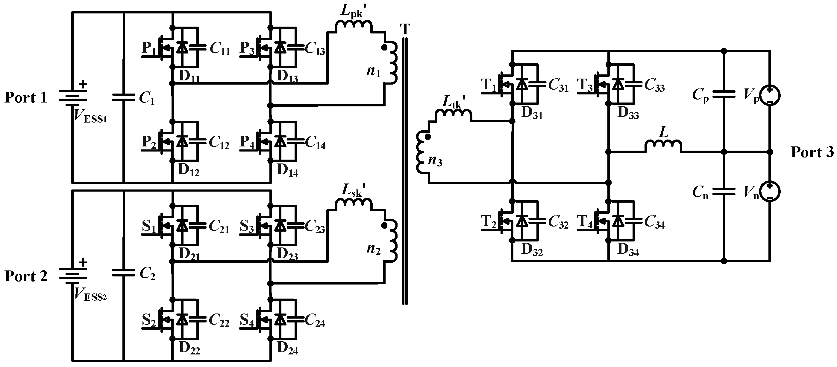
The proposed topology is shown in Figure 1. Port 1, Port 2, and Port 3 of the full bridge are connected by a three-winding high-frequency transformer with a turns ratio of n1:n2:n3. The leakage inductors of the transformer are Lpk’, Lsk’, and Ltk’ respectively. Port 1 and Port 2 are connected to the energy storage batteries VESS1 and VESS2 respectively, and Port 3 is connected to the bipolar buses. The upper and lower switches within the same bridge arm of each port operate in complementary conduction, while the diagonal switches within the bridge arm conduct simultaneously. φ12, φ13, and φ23 represent the phase shift angles between Port 1 and Port 2, Port 1 and Port 3, and Port 2 and Port 3, respectively. Among them, φ23 = φ13−φ12. The magnitude and direction of power transfer can be controlled by adjusting the phase shift angle, enabling energy transmission from the leading-phase port to the lagging-phase port.
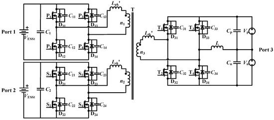
Figure 1.
The proposed topology.
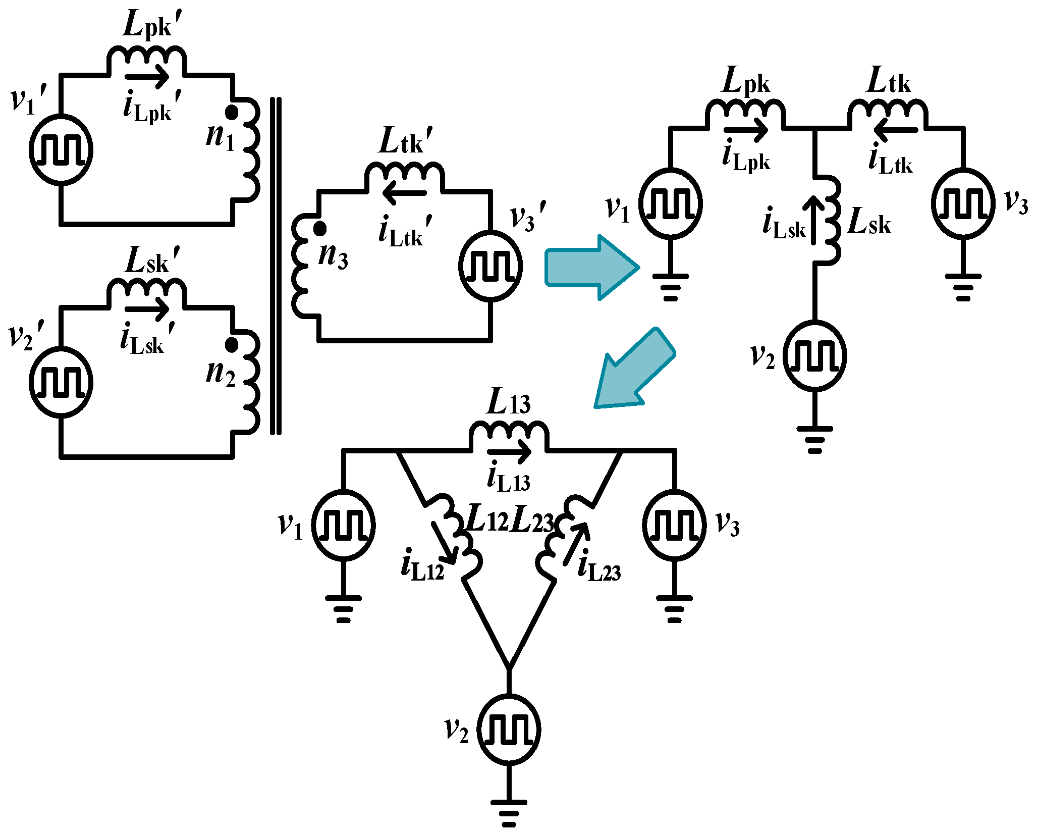
To facilitate the analysis of power flow, the equivalent circuit model of the converter after “Y–∆” transformation is shown in Figure 2. v1’, v2’, and v3’ are the input voltages before the reduction, respectively; v1, v2, and v3 are the input voltages after the reduction, respectively; Lpk, Lsk, and Ltk are the equivalent values of the inductors after the reduction, respectively; L12, L13, and L23 are the equivalent values of the inductors after the “Y–∆” transformation, respectively; and iL12, iL13, and iL23 are the corresponding inductor current values. To simplify the analysis, the following assumptions are made: (1) All switches and diodes are ideal devices, and the parallel diodes and capacitors of switches are their body diodes and junction capacitors. (2) The resonant frequencies of the parasitic capacitors and the leakage inductors are far less than the switching frequency of the converter.
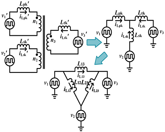
Figure 2.
The equivalent circuit model of the converter after “Y–∆” transformation.
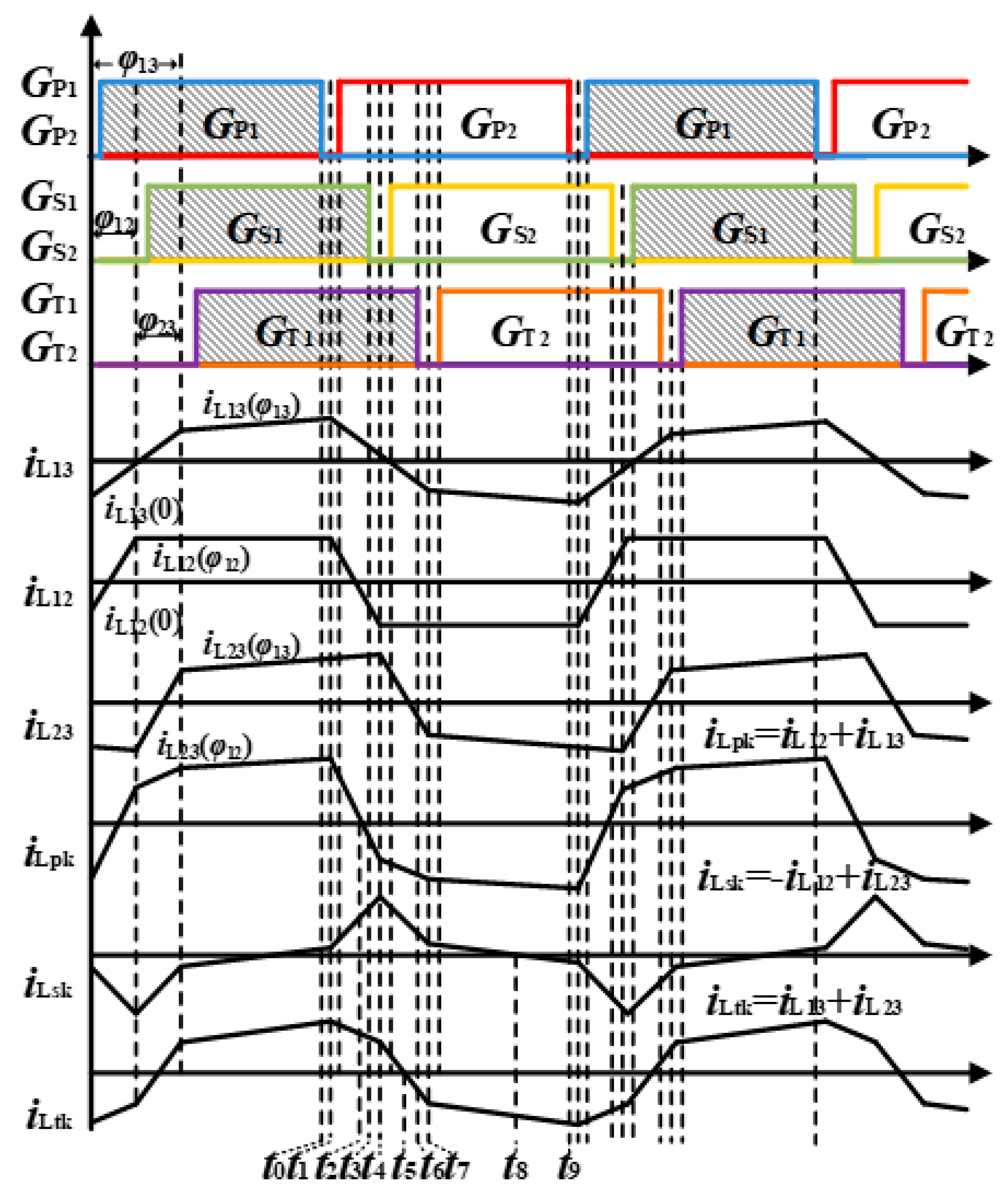
Taking the dual-input single-output mode (the energy storage batteries VESS1 and VESS2 supply power to the bipolar bus) as an example, the isolated three-port converter has 18 operating modes within one switching period. The key waveforms within one switching period are shown in Figure 3, and the specific modal analysis is as follows:
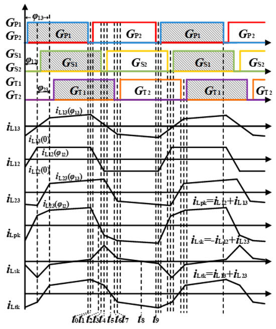
Figure 3.
The key waveforms of one switching period.
Mode 1 (t0–t1): The switches P1 and P4 are turned off simultaneously. The leakage inductor current iLpk charges the parasitic capacitors C11 and C14 and discharges the parasitic capacitors C12 and C13. At this time, the switches S1 and S4 in Port 2 are turned on, and the leakage inductor current iLsk gradually rises. The body diodes D31 and D34 in Port 3 are turned on.
Mode 2 (t1–t2): The parasitic capacitors C11 and C14 are charged to VESS1, and the parasitic capacitors C12 and C13 are discharged to zero. The body diodes D12 and D13 of the switches P2 and P3 are turned on for freewheeling, and the leakage inductor current iLpk starts to decrease. When the drive signals of the switches P2 and P3 arrive, since the leakage inductor current iLpk is positive, it still freewheels through the body diodes D12 and D13. At this time, there is a power backflow phenomenon at Port 1. The operating characteristics of the other two ports remain unchanged.
Mode 3 (t2–t3): When the leakage inductor current iLpk drops to zero, the drive signals of the switches P2 and P3 are still at a high level, and natural commutation occurs. Due to the clamping effect of the body diodes D12 and D13, the switches P2 and P3 are turned on with zero voltage switching (ZVS). The leakage inductor current iLpk continues to decrease; the operating characteristics of the other two ports remain unchanged.
Mode 4 (t3–t4): The switches S1 and S4 are turned off simultaneously. The leakage inductor current iLsk charges the parasitic capacitors C21 and C24 and discharges the parasitic capacitors C12 and C13. At this time, the switches P2 and P3 in Port 1 are turned on, the leakage inductor current iLpk continues to decrease, and the body diodes D31 and D34 in Port 3 are turned on.
Mode 5 (t4–t5): The parasitic capacitors C21 and C24 are charged to VESS2, and the parasitic capacitors C22 and C23 are discharged to zero. The body diodes D22 and D23 of the switches S2 and S3 are turned on for freewheeling, and the leakage inductor current iLsk starts to decrease. When the drive signals of the switches S2 and S3 arrive, since the leakage inductor current iLsk is positive, it still freewheels through the body diodes D22 and D23. At this time, Port 2 absorbs power, and the operating characteristics of the other two ports remain unchanged.
Mode 6 (t5–t6): At this time, the leakage inductor current iLtk drops to zero, and the current starts to flow in the reverse direction. The drive signals of the switches T1 and T4 in Port 3 are at a high level, and natural commutation occurs. Due to the clamping effect of the body diodes D31 and D34, the switches T1 and T4 are turned on with ZVS. The leakage inductor current iLsk continues to decrease, but it is still positive, so it still freewheels through the body diodes D22 and D23. Port 3 supplies power, whereas Port 2 remains in power absorbing state.
Mode 7 (t6–t7): The switches T1 and T4 are turned off simultaneously. The leakage inductor current iLtk charges the parasitic capacitors C31 and C34 and discharges the parasitic capacitors C32 and C33 at the same time. The operating characteristics of the other two ports remain unchanged.
Mode 8 (t7–t8): The parasitic capacitors C31 and C34 are charged to (Vp + Vn), and the parasitic capacitors C32 and C33 are discharged to zero. The body diodes D32 and D34 of the switches T2 and T3 are turned on for freewheeling. The operating characteristics of the other two ports remain unchanged.
Mode 9 (t8–t9): At this time, the leakage inductor current iLsk drops to zero, and the current starts to flow in the reverse direction. The drive signals of the switches S2 and S3 in Port 2 are at a high level, and natural commutation occurs. Due to the clamping effect of the body diodes D22 and D23, the switches S2 and S3 are turned on with ZVS, and Port 2 supplies power.
Starting from t9, the converter starts working for another half period. Its operating mode is symmetrical to the above half period, and further elaboration on it is not necessary.
3. Performance Characteristics
3.1. Analysis of Transmitted Power
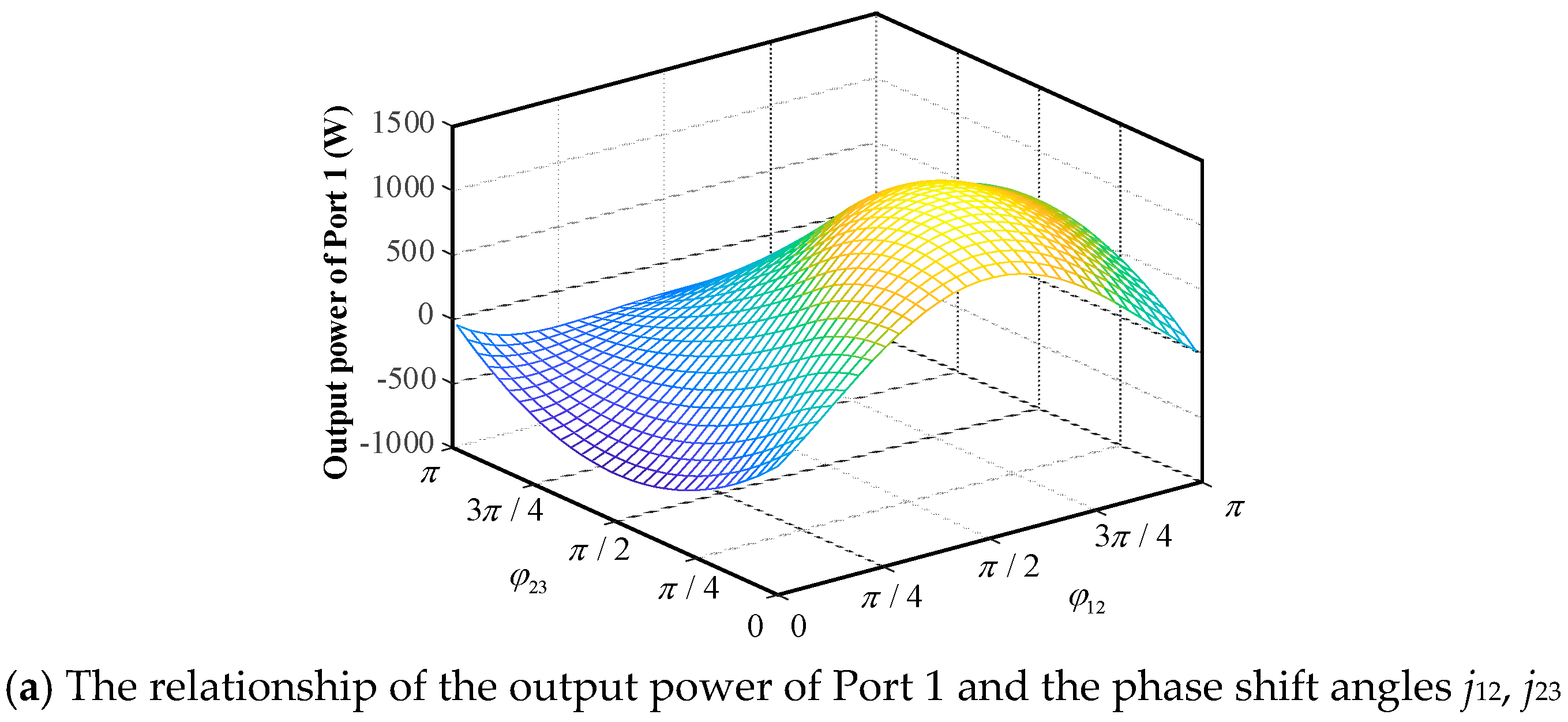
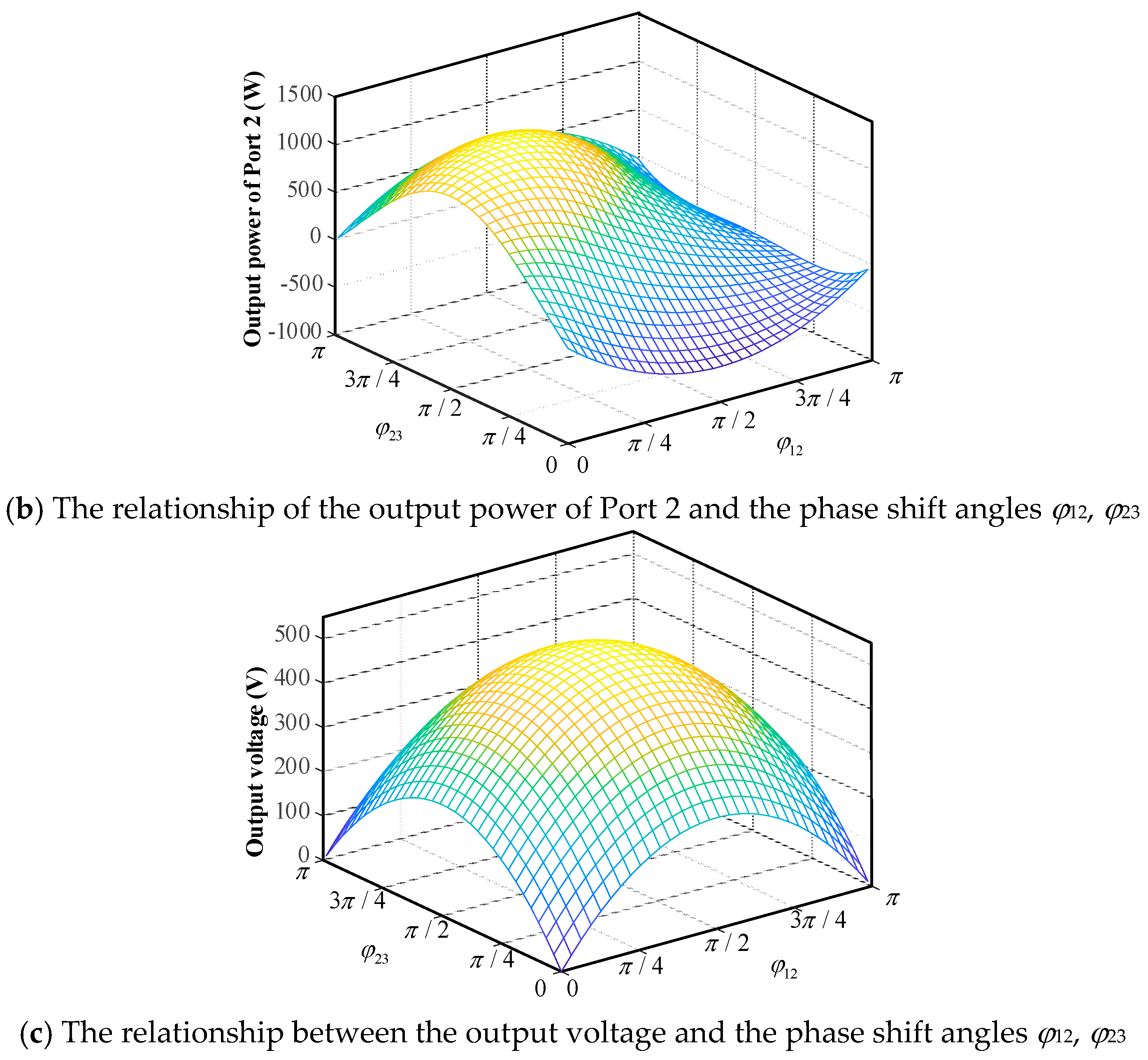
Based on the equivalent circuit shown in Figure 2 and combined with the modal analysis, the magnitudes of the powers P13, P12, and P23 transmitted on the equivalent inductors L13, L12, and L23 can be calculated, as shown in Equation (1); and the actual transmitted powers P13, P12, and P23 of each port can be obtained by superposition based on the KCL circuit theorem. The flow direction and magnitude of the port power can be controlled by adjusting the phase shift angles φ12 and φ23, as shown in Figure 4a,b.
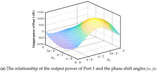
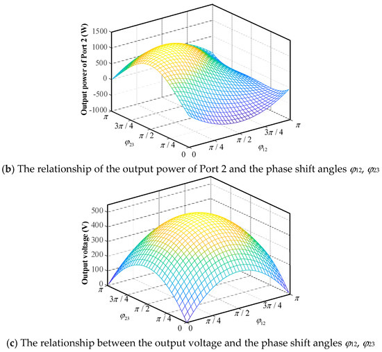
Figure 4.
The relationship between power, voltage, and phase shift angles.
When Port 3 is connected to a load simulating the operation of bipolar bus, the forward power transfer relationship can be expressed by Equation (2). The output voltage exhibits symmetrical characteristics with respect to the phase shift angles φ12 and φ23, as shown in Figure 4c. The existence of power backflow leads to additional losses with increasing phase shift angle; thus, the phase shift angle is generally constrained to the range of [0, π/2].
In Equation (2), VCp, VCn, VC1, and VC2 represent the voltages of capacitors Cp, Cn, C1, and C2 respectively; Rp and Rn represent the equivalent loads of the bipolar bus; and fs represents the switching frequency.
Similarly, the reverse power transmission relationship can be expressed as Equation (3):
In Equation (3), Rb1 and Rb represent the equivalent internal resistances of the batteries VESS1 and VESS2, respectively.
3.2. Analysis of Voltage and Current Stress
According to the working principle of the converter, the voltage stress of the switches in each full-bridge port is the corresponding port voltage, as shown in Equation (4).
In Equation (4), VP1~VP4, VS1~VS4, VT1~VT4 are the port voltages of the switches, respectively; Vp is the voltage between the P-Z pole; and Vn is the voltage between the Z-N pole.
The current stress of the switches in each full-bridge port is the leakage inductor current of the corresponding port before turn-off. According to the power transmission relationship of the converter and the KCL principle, let w = 2πfs. The leakage inductor current of each port can be calculated, and the current stress of the switches are shown in Equation (5).
3.3. Analysis of the Voltage Self-Balancing Mechanism
3.3.1. The Principle of the Inter-Pole Voltage Self-Balancing
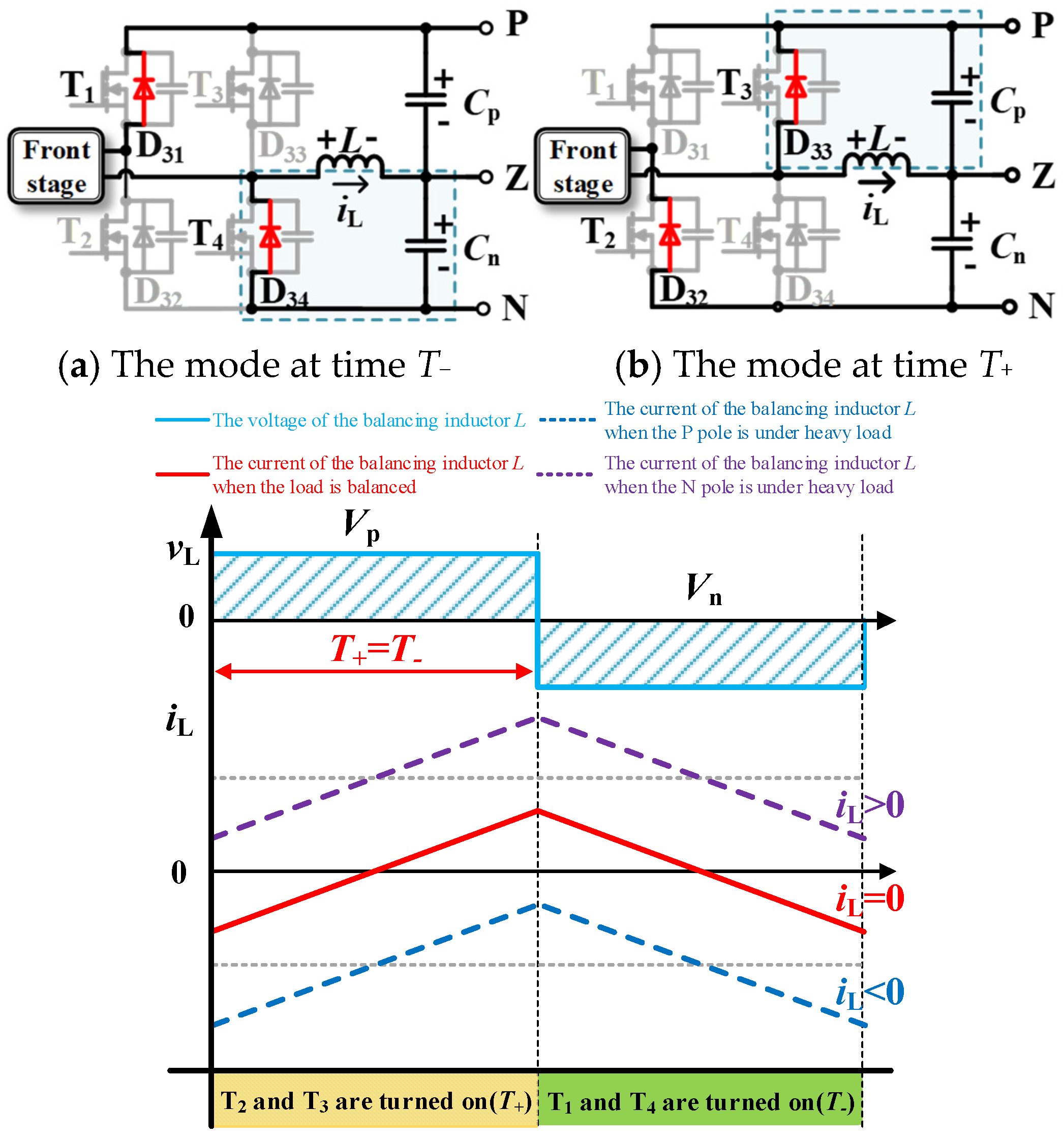
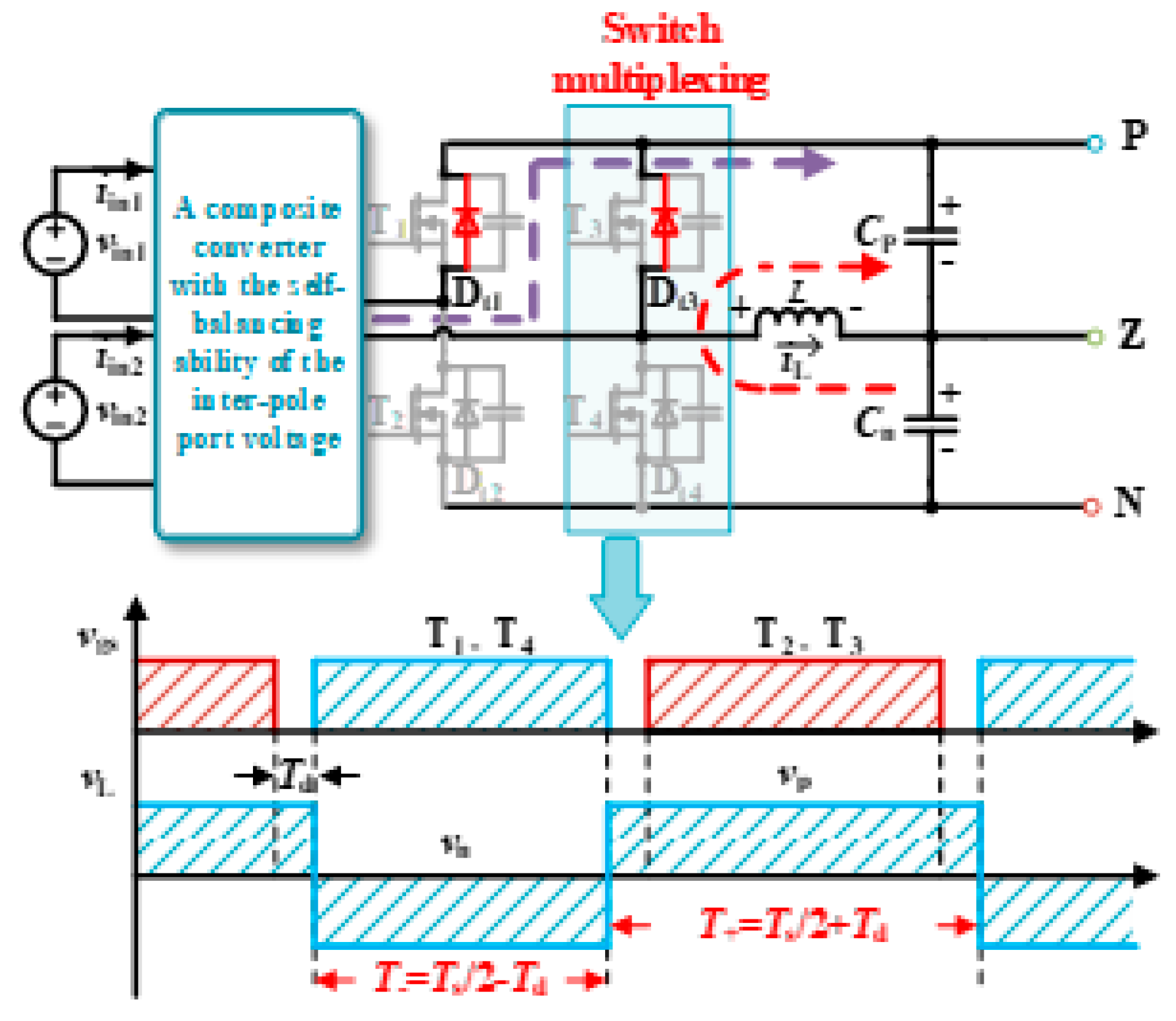
When the switch T4 is turned on, the balancing inductor L is connected in parallel with the capacitor Cn through the switch T4, and the voltage on the balancing inductor L is VL = −Vn, as shown in Figure 5a. When the switch T3 is turned on, the balancing inductor L is connected in parallel with the capacitor Cp through the switch T3, and the voltage on the balancing inductor L is VL = Vp, as shown in Figure 5b. The switches T3 and T4 on the same bridge arm operate complementarily, both conducting for half of the switching period (that is, T+ =T− = Ts/2, where T+ and T− are the conduction times of the positive and negative half-periods, respectively, and Ts is the switching period), as shown in Figure 5c. According to the inductor volt-second balance principle, the voltages of the bipolar output ports are clamped to the same level, thereby achieving automatic voltage balancing between the poles.
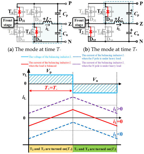
Figure 5.
The principle of inter-pole voltage self-balancing.
3.3.2. Balancing Inductor Design
Due to the existence of the balancing inductor, the power of the bipolar bus can be redistributed. Under unbalanced load conditions, the average current of the balancing inductor is not zero, and its relationship with the unbalanced power is shown in Equation (6). Let ΔP = Pn − Pp, where Pp and Pn are the load powers of the positive and negative poles, respectively:
In Equation (6), iL is the average current flowing through the balancing inductor. in and ip are the load currents of the positive and negative poles, respectively.
Within one switching period, the current ripple of the balancing inductor L is shown in Equation (7):
From Equations (6) and (7), the constraint condition of the inductor can be derived as shown in Equation (8):
Among them, is the current ripple coefficient, and the common value is 5%; ∆P represents the processed unbalanced power, calculated based on the worst-case scenario (i.e., one pole at full-load while the other pole at no-load).
3.3.3. Analysis of the Voltage Self-Balancing Ability of the Proposed Converter
To characterize the regulation characteristics of the proposed converter under bipolar bus unbalance conditions, the following model is established:
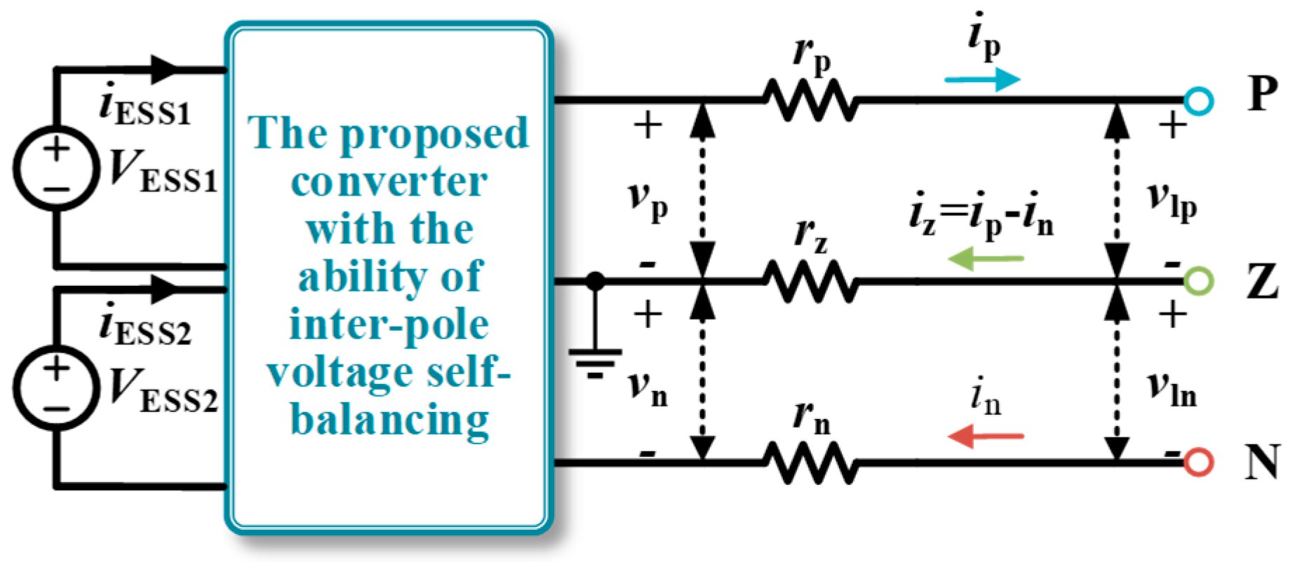
P, N, and Z represent the three buses of the bipolar DC microgrid, and rp, rz, and rn are the equivalent line impedances, as shown in Figure 6. Assume that the output voltage amplitudes of the converter at this time are vp and vn. The currents flowing through the bipolar buses are ip, iz, and in. The voltage amplitudes between the bipolar buses are vlp and vln. There is an unbalanced voltage between the poles, and the voltage difference is ∆V. The power that can be processed by the converter is P. The self-balancing power is defined as the magnitude of power balanced by the converter under the inter-pole unbalanced voltage. To simplify the analysis process, the parasitic parameters of the converter devices are ignored.
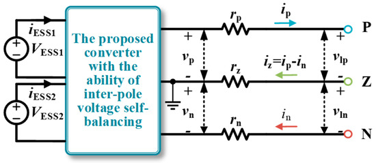
Figure 6.
The equivalent model of the proposed converter integrated into bipolar DC microgrid.
To simplify the analysis, the equivalent line impedance is assumed to be equal to rp = rn = rz = r. According to the KVL principle, the relationship between the output voltage of the converter and the bipolar buses voltage with respect to the line impedance is shown in Equation (9):
The power equation of the proposed converter is shown in Equation (10), where D13 = j13/p and D23 = j 23/p:
Due to the volt-second balance of the inductor, the output voltages of the converter can be maintained as vp = vn. From Equations (9) and (10), the current magnitude relationship of different connection points can be obtained as shown in Equation (11).
Therefore, when there is a deviation in the buses, the unbalanced power processed by the converter is calculated as shown in Equation (12), which describes the relationship between the balanced power and the external environment (the voltage difference between the poles and the line impedance) and the internal environment (converter real-time processing power).
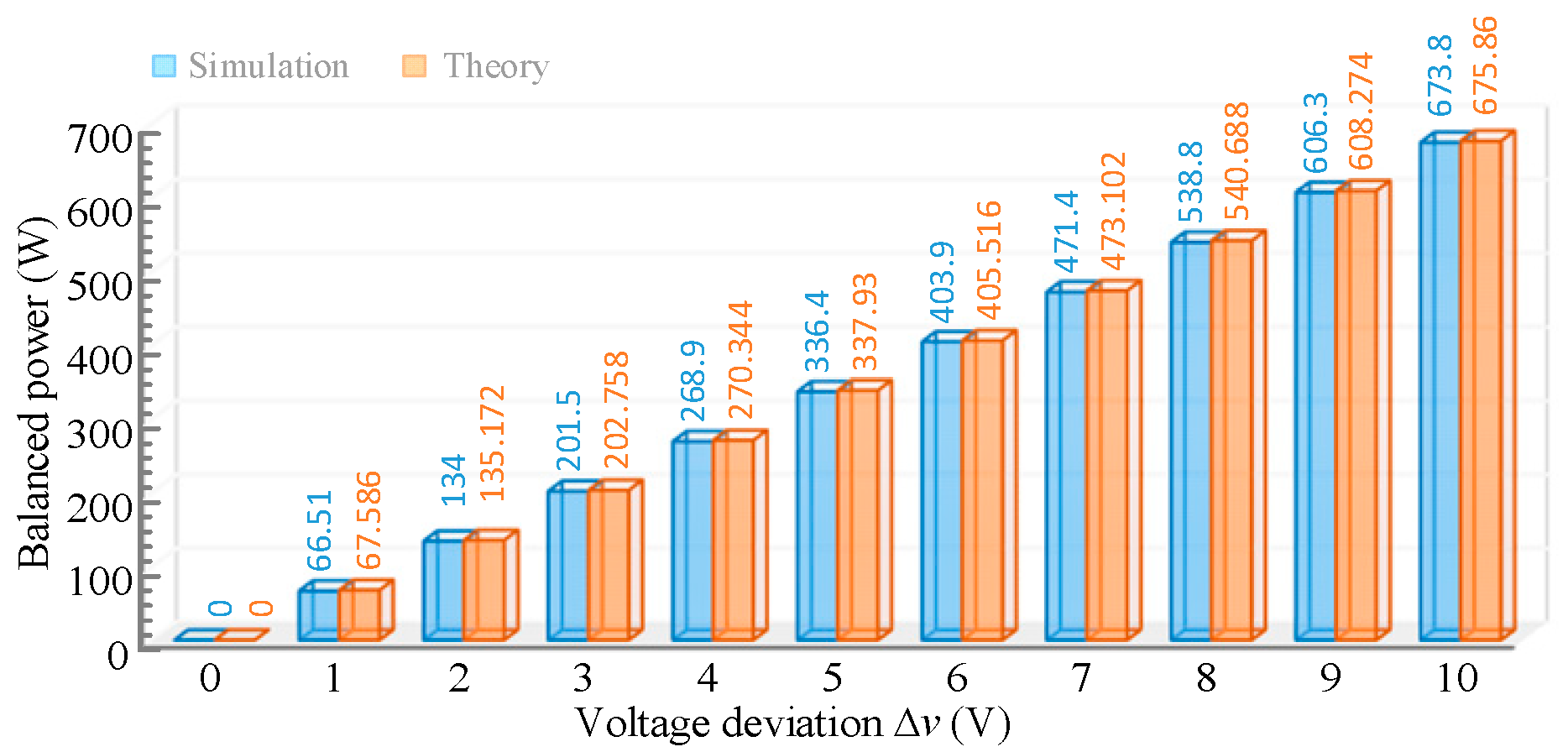
The comparison of simulation and theoretical calculation results of the converter under different unbalanced voltages is shown in Figure 7. It can be seen from the figure that the error between the theory and the simulation is small, which verifies the correctness of Equation (12). The main reason for the error is the influence of the capacitor and inductor ripple of the converter.
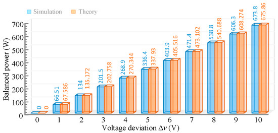
Figure 7.
Theoretical and simulation comparison results of power balancing capability under different voltage deviations.
However, when the unbalanced power to be processed exceeds the rated power range of the converter, there will be a deviation between vp and vn. The main reason is that the conduction state of the switching periods changes during the dead time, resulting in inconsistent durations of the positive and negative periods of the balancing inductor voltage. The additional unbalanced power will be regulated by the balancing inductor, flowing from the bus with higher voltage to the bus with lower voltage. As shown in Figure 8, the voltage of the N-pole is higher than that of the P-pole. When the switch T4 is turned off, the current of the balancing inductor will continue to flow through the body diode of the switch T2, and the duration of the positive half-period of the balancing inductor voltage will be 2Td longer than that of the negative half-period. According to the volt-second balance principle of the inductor, the following Equation (13) can be obtained:
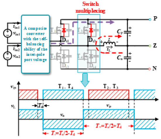
Figure 8.
Analysis of voltage deviation caused by dead-time transformation.
Therefore, the expression of the unbalanced voltage can be obtained as shown in Equation (14):
4. Analysis of Soft Switch Implementation Range
The condition for the switch to achieve ZVS is that the inductor stored energy is sufficient to discharge the energy stored in the junction capacitor before the switch is turned on. Due to the symmetry of the port currents, when switches P1 and P4 at Port 1 achieve ZVS, switches P2 and P3 can also achieve ZVS, and this principle also applies to Ports 2 and 3.
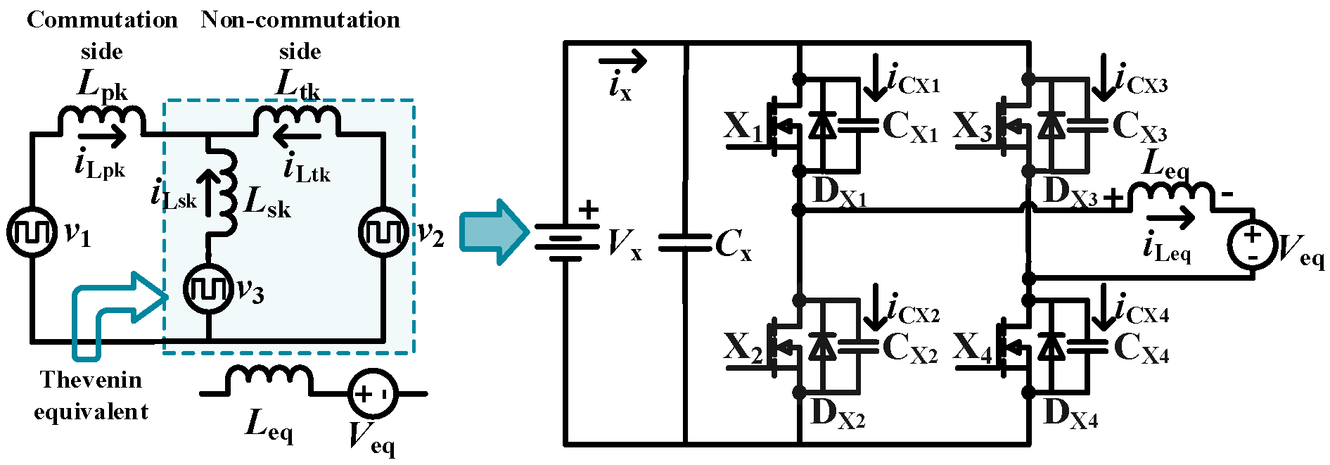
The Y-type circuit after Thevenin equivalent simplification is shown in Figure 9. Take the switches X2 and X3 turned off and switches X1 and X4 turned on as an example: at this stage, iLeq < 0. According to the KCL principle of the circuit node, Equation (15) can be obtained.
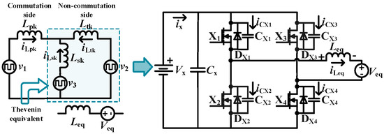
Figure 9.
Simplified circuit after Thevenin equivalence.
For simplified analysis, it is uniformly assumed that the parasitic capacitor value of the drain source of the switch is Cds. vCX1, vCX2, vCX3 are the voltages of the capacitors CX1, CX2, CX3. From the perspective of energy, the energy difference ∆E between the input side and the output side is shown in Equation (16). This part of the energy difference is provided by the energy ELeq stored in the inductor.
When ∆E < 0, the energy stored in the inductor decreases. Taking iLeq(td) = 0 as the limit, td is the end time of the dead time. While maintaining directional requirements, the inductor current magnitude is also constrained by the condition ELeq > ∆E, as specified in Equation (17):
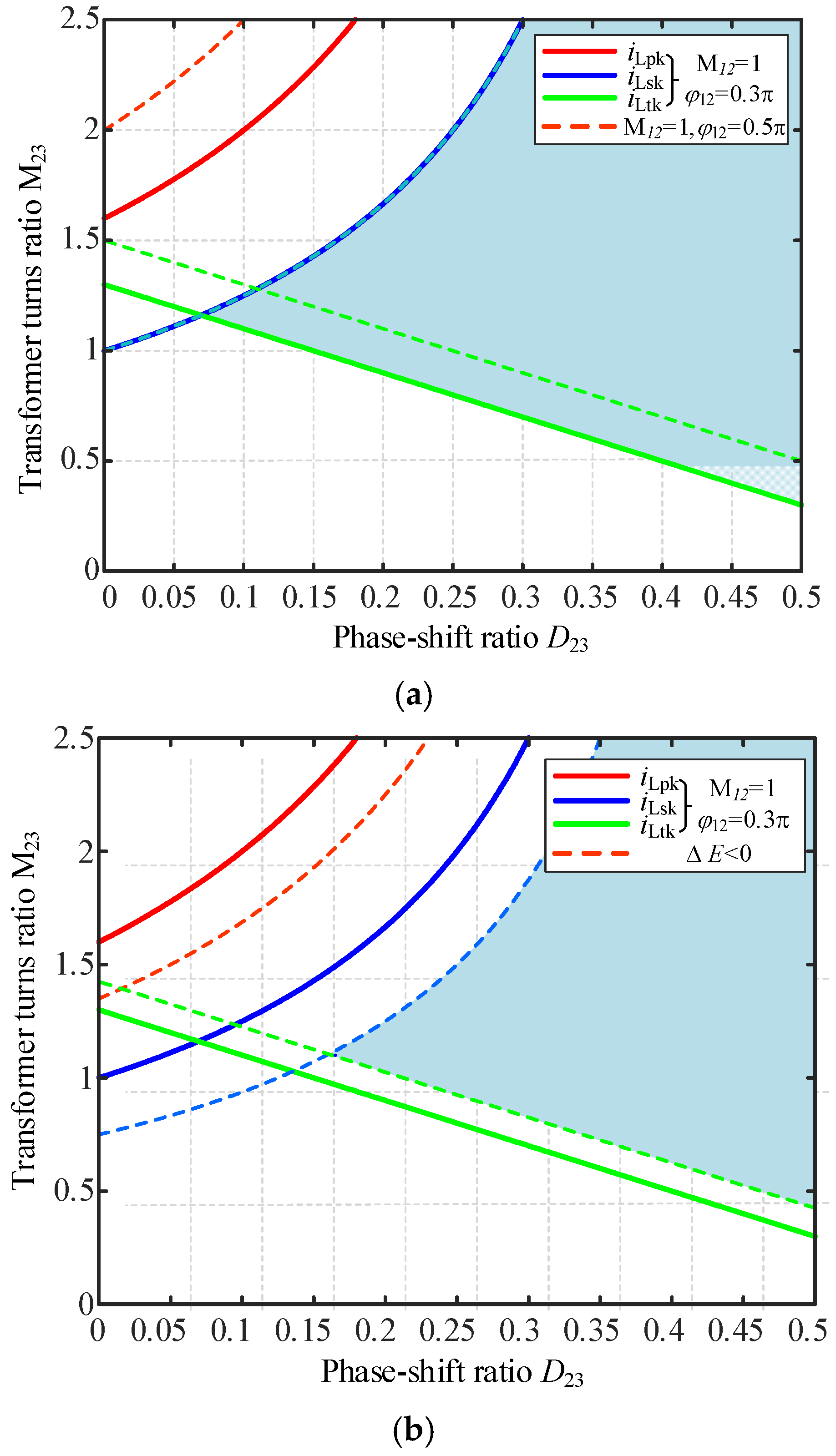
When ∆E > 0, the energy stored in the inductor increases, and only the requirement of current directionality needs to be met, that is, iLeq < 0. Let L12 = L13 = L23 = Lk, VESS2/VESS1 = M12, Vdc/VESS1 = M13. According to the conservation of node current, the current flowing through the switches at each port when the switch is turned on can be obtained as shown in Equation (18). According to the analysis of Figure 10, due to the power coupling of the converter, when the other port is heavily loaded or in the case of ∆E < 0, the range for realizing soft switching will be reduced. When the turns ratio of the transformer is close to 1, there will be a wider range for realizing soft switching.
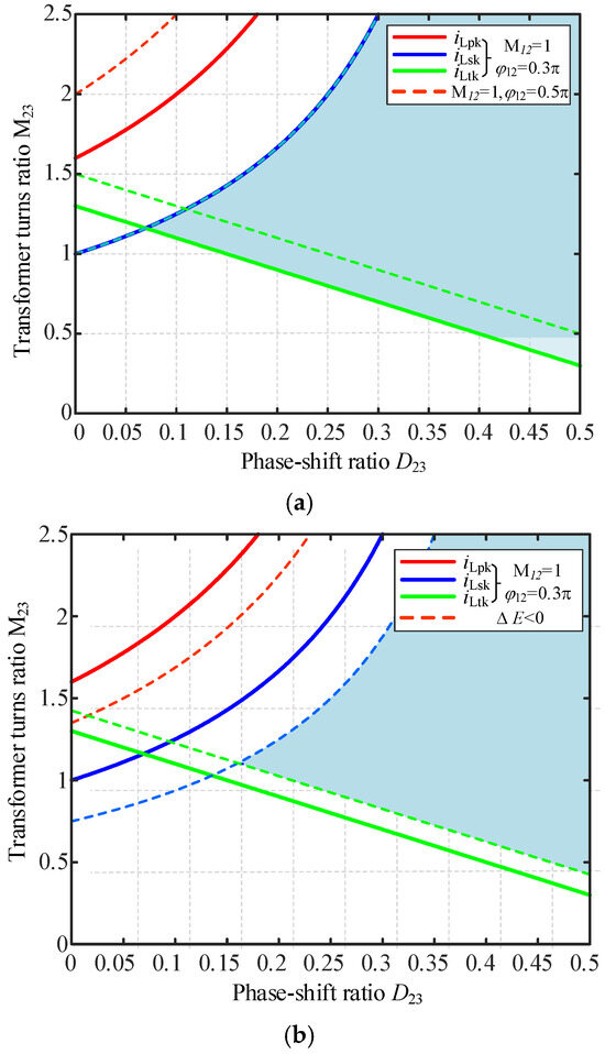
Figure 10.
Implementation range of soft switching. (a) When ΔE > 0, the leakage inductor energy does not need to be considered. (b) When ΔE < 0, the leakage inductor energy needs to be considered.
5. Simulation and Experimental Verification
To verify the voltage self-balancing ability of the proposed converter in the microgrid, a 400 V DC voltage source is connected to both ends of the positive and negative buses to simulate the rectification from the high-voltage grid into the DC bus. A load with RP = 50 Ω and RN = 200 Ω is used to simulate the unbalanced loads at the two poles of the bipolar DC bus. The simulation model of the proposed converter has a rate power of 1 kW and an output voltage of ±200 V.
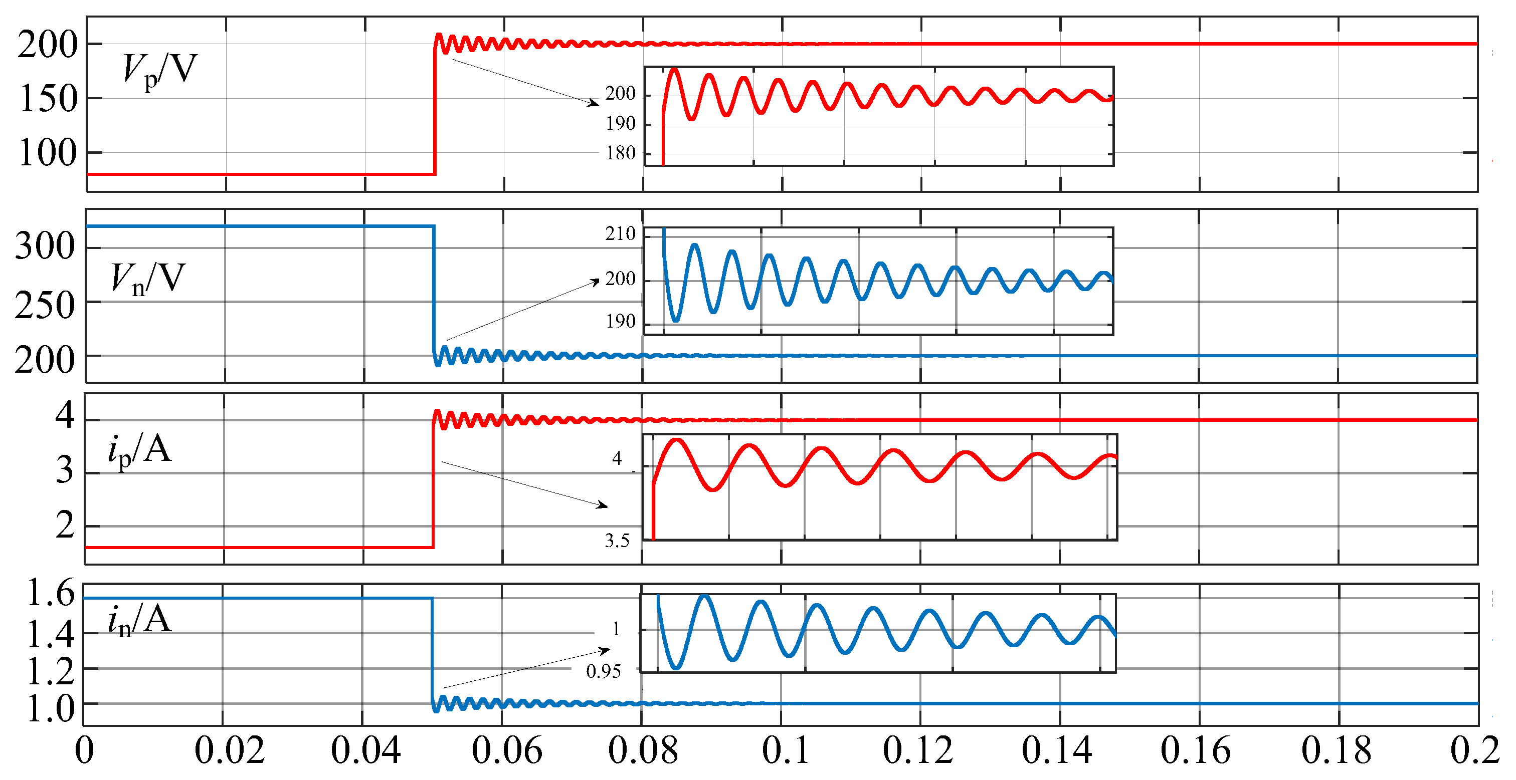
The simulation results are shown in Figure 11. It can be seen from the simulation results that before 0.05 s, when the proposed converter is not put into operation, the unbalance of the load causes the bipolar bus voltages to operate asymmetrically at 80 V and 320 V. At 0.05 s, the proposed converter is put into operation. After a short oscillation of 0.03 s, the bipolar bus voltages are 199.3 V and 200.7 V, respectively, achieving a voltage balance rate of 0.35% and basically achieving inter-pole voltage balance. These results demonstrate that the proposed converter has the voltage self-balancing capability. When the inter-pole voltage of the bipolar DC microgrid is unbalanced, it can preferentially provide more energy to the bus with lower voltage, effectively reducing the voltage asymmetry.
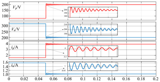
Figure 11.
System simulation verification.
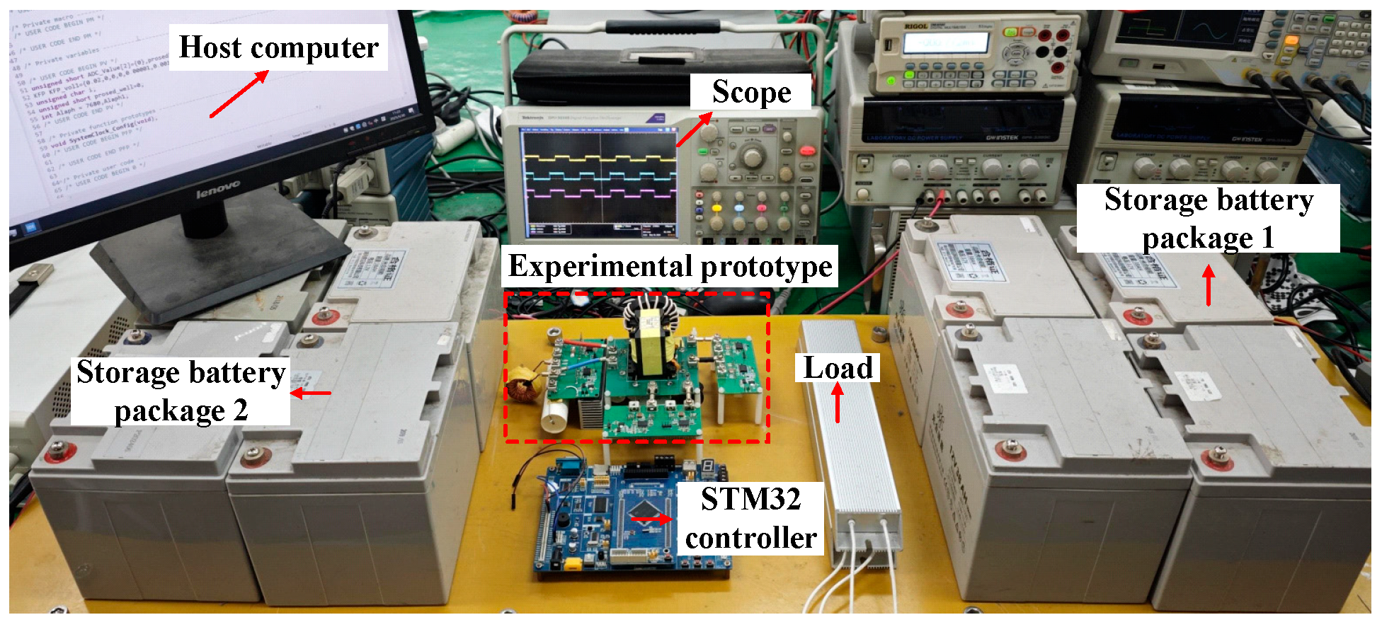
To validate the correctness of the above theoretical analysis, an experimental prototype with a rated output power of 1 kW is constructed. The experimental prototype is shown in Figure 12, and the detailed parameters are listed in Table 1.
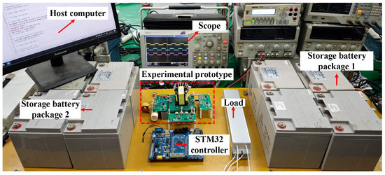
Figure 12.
Experimental prototype.

Table 1.
Experimental prototype parameters.
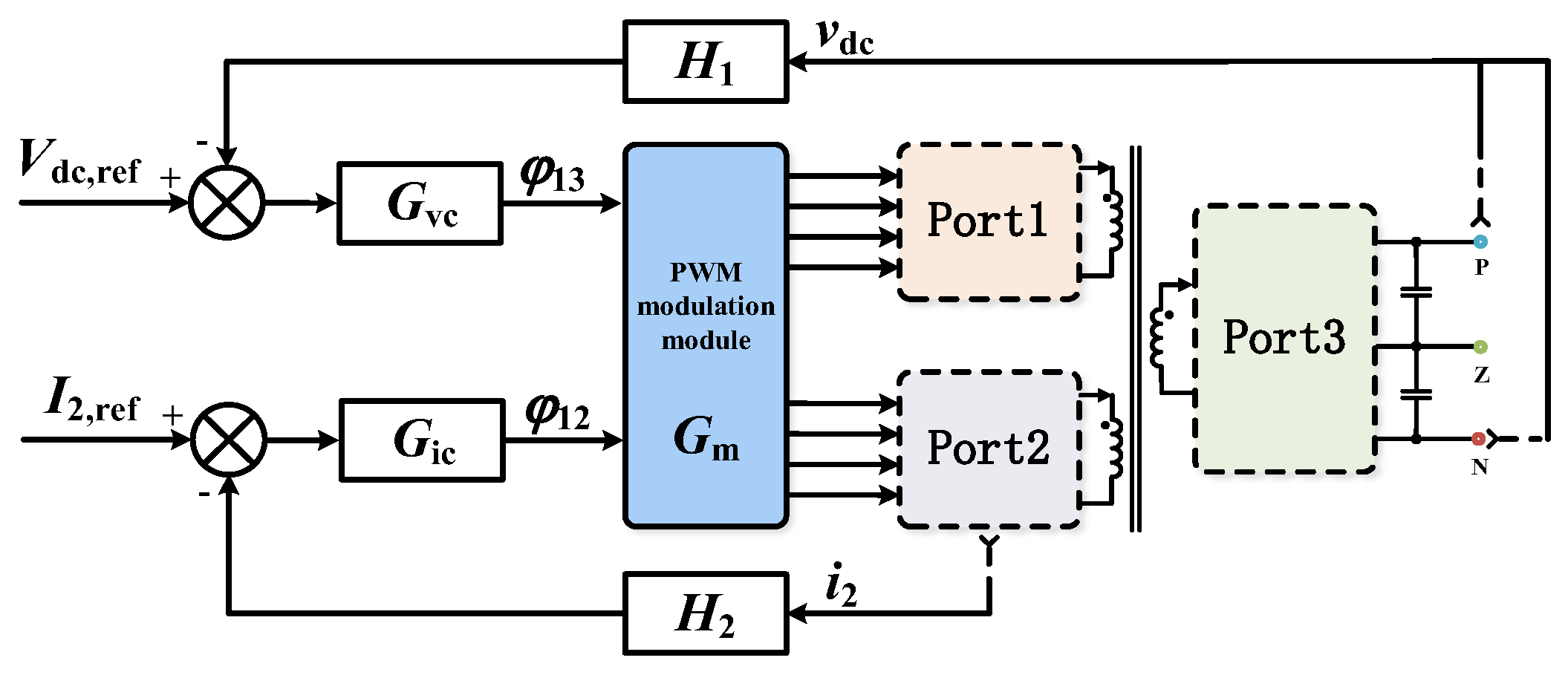
The proposed topology operates at a switching frequency of 100 kHz, with an ADC sampling frequency of 857 kHz. The dead time was set to 1 μs. The controller used was an STM32F103ZET6 microcontroller running at a system frequency of 72 MHz. For the operational state where two input power sources simultaneously supply a bipolar load, the control system designed in this paper is illustrated in Figure 13. The overall control strategy is as follows: Port 1 and Port 2 are connected to batteries, whose voltages can be considered constant. The input power of Port 2 is controlled by controlling its input current, while Port 3 is connected to a load emulating a DC microgrid, whose voltage requires control. The control system does not directly adjust the power of the battery at Port 1. Under the single-phase-shift modulation strategy adopted in this work, the input/output power at Port 1 naturally equals the power difference between Port 2 and Port 3. By leveraging the principle of power conservation, the battery automatically charges or discharges to compensate for the imbalance between the power generated by the battery at Port 2 and the power demand at the DC microgrid port. Thus, while the control system explicitly regulates the power at Ports 2 and 3, the power at Port 1 is indirectly and automatically controlled.
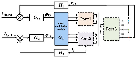
Figure 13.
The control algorithm for the proposed topology.
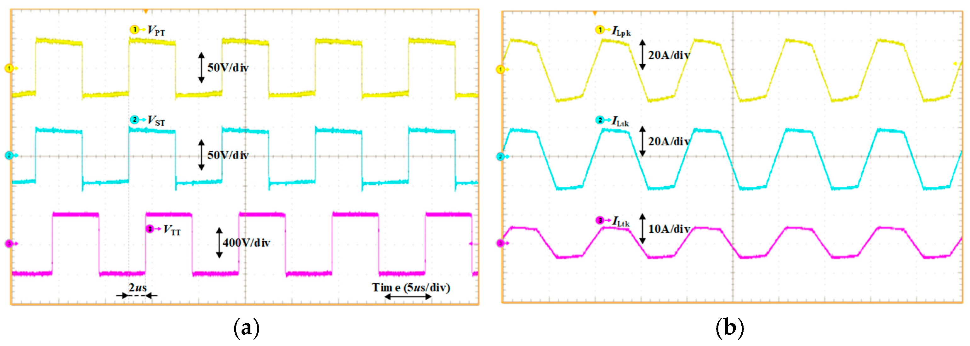
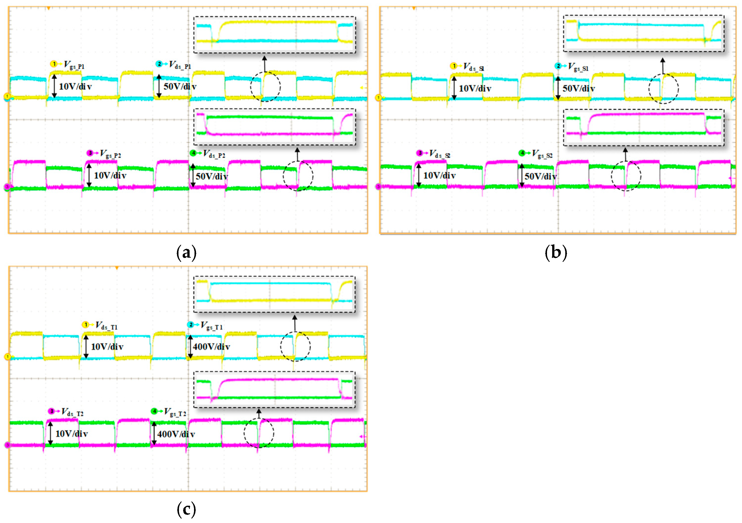
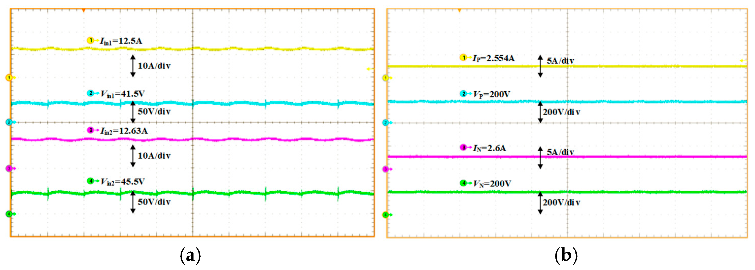
The experimental waveforms are presented in Figure 14. The voltage waveforms of each transformer winding are depicted in Figure 14a, where VPT, VST, and VTT represent the port voltages of the transformer’s primary, secondary, and tertiary sides, respectively. Considering the losses, the phase shift ratio is set to 0.38 to achieve the required voltage. The current waveforms of each transformer winding are shown in Figure 14b. The average value of the leakage inductor current over one period is zero, indicating no DC bias. Figure 15a–c illustrates the realization of soft switching for the switches in the three full-bridge structures, respectively. The waveforms indicate that all switches achieve ZVS, thereby effectively reducing switching losses. Figure 16a,b are the input and output voltage and current waveforms under the balanced condition (RP = 80 Ω, RN = 80 Ω).
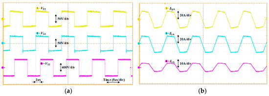
Figure 14.
Transformer winding waveform. (a) Transformer winding voltage waveform (b) Transformer winding current waveform.
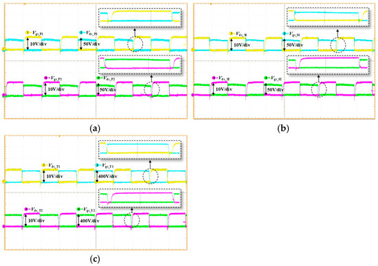
Figure 15.
The driving and switch waveforms. (a) The driving and voltage waveforms of the switches at Port 1 (b) The driving and voltage waveforms of the switches at Port 2 (c) The driving and voltage waveforms of the switches at Port 3.
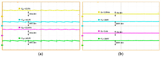
Figure 16.
Input and output voltage and current waveforms under balanced power. (a) Input voltage and current waveforms (b) Output voltage and current waveforms under balanced power.
The effectiveness of voltage self-balancing is typically evaluated using the inter-pole voltage unbalance factor (VUF%) [26], which is defined as follows:
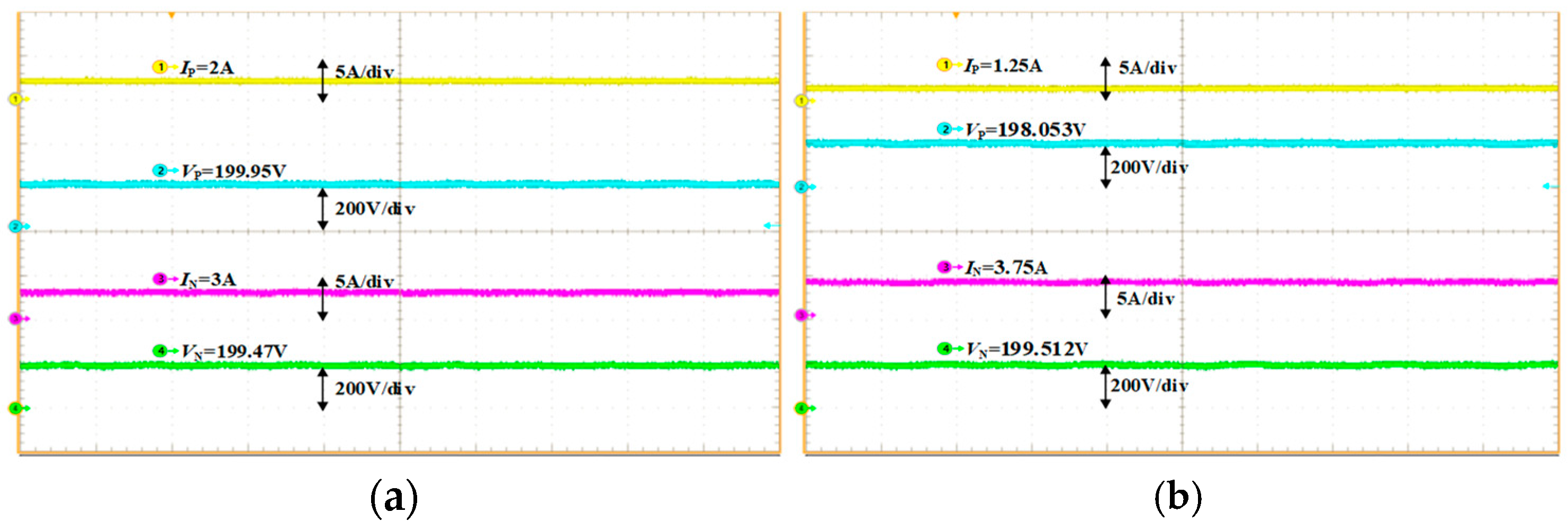
Under the experimental conditions of this study, Figure 17a,b presents the output voltage and current waveforms under unbalanced power conditions of 200 W (RP = 100 Ω, RN = 66.7 Ω) and 500 W (RP = 160 Ω, RN = 53.3 Ω), respectively. The measured inter-pole voltage deviations were 0.48 V and 1.459 V, corresponding to VUF% values of 0.12% and 0.36%, respectively, demonstrating the effectiveness of the voltage self-balancing capability of the proposed converter.
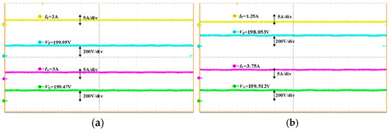
Figure 17.
Output voltage and current waveforms under unbalanced power condition. (a) Output voltage and current waveforms under 200 W unbalanced power condition; (b) output voltage and current waveforms under 500 W unbalanced power condition.
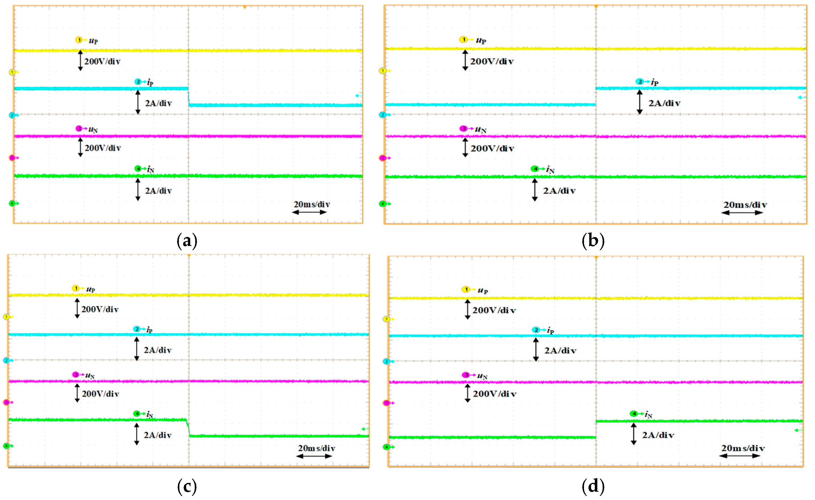
Figure 18a,b shows the voltage and current waveforms when the positive load RP steps up from 80 Ω to 200 Ω and steps down from 200 Ω to 80 Ω, respectively. As observed, when RP steps up from 80 Ω to 200 Ω, the output current iP decreases from 2.5 A to 1 A, and the positive and negative output voltages stabilize at 200 V after a 20 ms transient with an overshoot of only 5 V. When RP steps down from 200 Ω to 80 Ω, the output current iP increases from 1 A to 2.5 A, and the output voltages also return to 200 V within 20 ms with the same 5 V overshoot. Similarly, Figure 18c,d presents the voltage and current waveforms during step changes in the negative load RN between 80 Ω and 200 Ω, which exhibit behavior consistent with that of RP. These results validate the stability of the closed-loop control system, demonstrating excellent disturbance rejection and fast dynamic response.
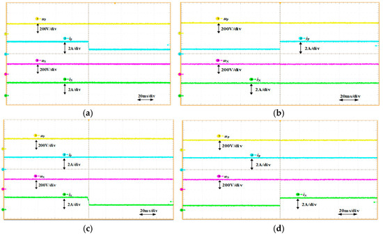
Figure 18.
Waveforms of the closed-loop load step test. (a) The load resistance RP steps from 80 Ω to 200 Ω (b) The load resistance RP steps from 200 Ω to 80 Ω (c) The load resistance RN steps from 80 Ω to 200 Ω (d) The load resistance RN steps from 200 Ω to 80 Ω.
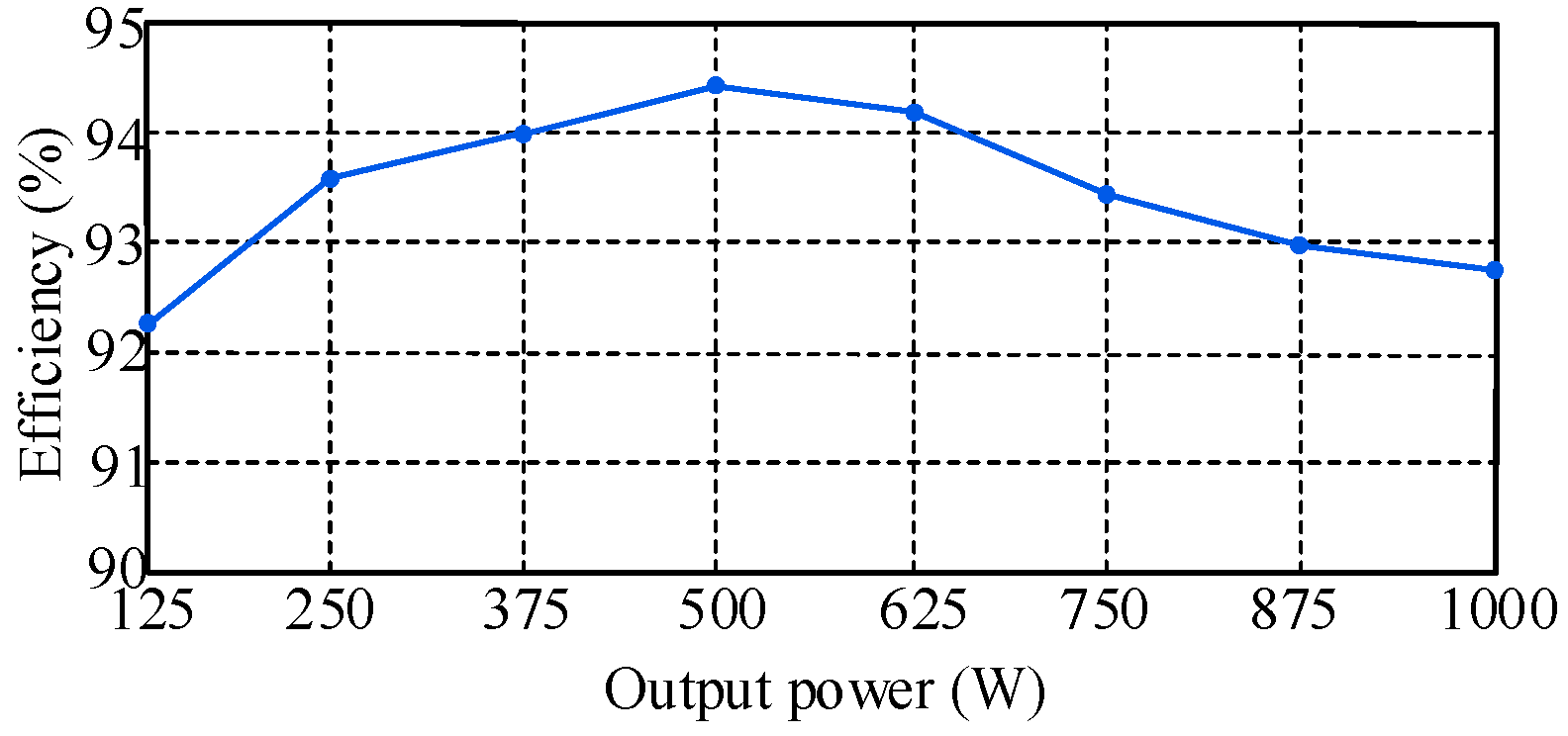
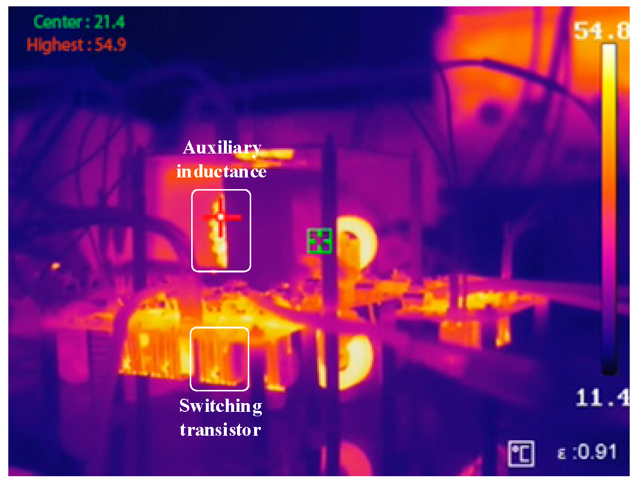
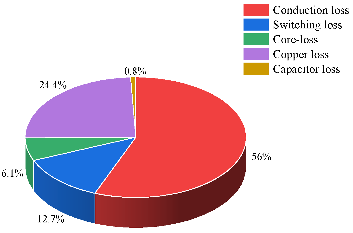
Figure 19 illustrates the efficiency of the experimental prototype. It is observed that as the output power gradually increases, the converter’s efficiency exhibits a trend of first increasing and then decreasing. The prototype achieves a peak efficiency of approximately 94.3% at an output power of 500 W, and the efficiency at the rated power of 1 kW is 92.7%. Figure 20 shows the thermal imaging of the prototype under the rated power of 1 kW. It can be seen from the figure that the switches have a lower temperature due to the realization of soft switching, and the highest temperature appears in the auxiliary inductor connected in series with the transformer, which is 54.9 °C. Figure 21 is the theoretical loss distribution of the proposed converter under the rated power condition. The losses are mainly switching losses, inductor losses, and transformer losses, accounting for about 94.12% of the total losses, while the losses of capacitors, drivers, and others are small, only accounting for 5.88%.
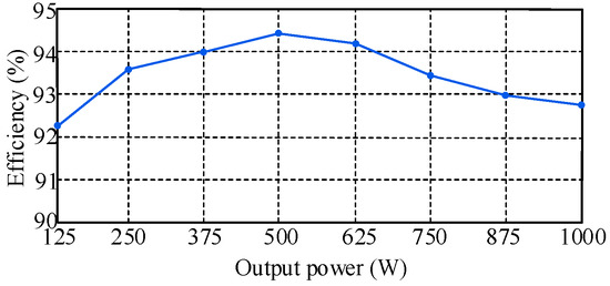
Figure 19.
Efficiency of the converter.
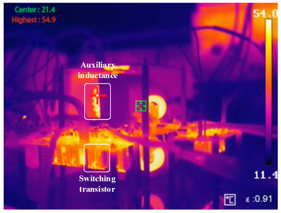
Figure 20.
Thermal imaging of the prototype.
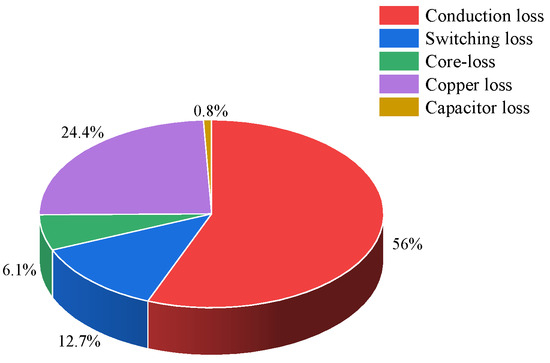
Figure 21.
Loss distribution diagram.
6. Performance Comparison and Analysis
Table 2 presents a comparison between the proposed converter and existing common bidirectional grid-energy storage voltage balancers. The approach of combinatorial transformation based on the basic topology is proposed in [10,17]. This solution can achieve voltage self-balancing but fails to provide electrical isolation, resulting in relatively low safety. The method of connecting two ports of a TAB in series to achieve bipolar output is proposed in [23], but its voltage balancing relies on a complex control system. The approach of introducing a balancing inductor based on DAB to achieve voltage self-balancing is proposed in [27]. However, compared with this, the proposed topology features more flexible power flow. Furthermore, the proposed converter does not require detection results of voltage unbalance and can automatically redistribute and process the inter-pole unbalanced power. Meanwhile, it has the advantages of flexible power regulation and high-power supply reliability.

Table 2.
Performance comparison between the proposed converter and other converters.
7. Conclusions
This paper proposes an isolated bipolar bidirectional multi-port converter with inherent inter-pole voltage self-balancing capability. The power flow can be flexibly controlled through phase shift control while autonomously maintaining voltage balance between the poles. The results demonstrate that the proposed converter offers the following advantages:
- (1)
- The proposed converter features inherent self-balancing output voltage characteristics. Under unbalanced load conditions, it can autonomously redistribute power between the poles to maintain balanced output voltages, without relying on complex voltage sampling and control systems to sustain symmetric operation of the bipolar output.
- (2)
- The proposed converter supports multi-port input and bidirectional energy exchange. Phase shift control enables flexible power flow regulation and precise management of energy distribution among multiple input ports. Additionally, the high-frequency transformer provides electrical isolation, making the converter well-suited for high-power applications with enhanced operational safety and reliability.
- (3)
- The proposed converter achieves Zero Voltage Switching (ZVS) for its power switches, significantly reducing switching losses. This capability enhances overall efficiency and extends the operational lifespan of the components, thereby ensuring highly efficient performance even under high-frequency switching conditions.
Author Contributions
Conceptualization, S.W.; Methodology, S.W., Z.L. and B.Z.; Validation, Z.L., Z.Z. and B.Z.; Formal analysis, C.L., Z.L. and H.Z.; Data curation, C.L.; Writing—original draft, S.W.; Writing—review & editing, C.L., Z.Z. and H.Z.; Visualization, Z.Z.; Supervision, B.Z. All authors have read and agreed to the published version of the manuscript.
Funding
This work was supported in part by the Guangxi Key Research and Development Plan Project (Grant No. AB23026037) and in part by the Key Research Plan Program of Education Department of Hubei Province (Grant No. D20231201).
Data Availability Statement
Data are contained within the article.
Conflicts of Interest
Authors Shusheng Wang, Chunxing Lian and Zhe Li were employed by the company China Water Resource Northeast Investigation Design and Research Co., Ltd. The remaining authors declare that the research was conducted in the absence of any commercial or financial relationships that could be construed as a potential conflict of interest.
References
- Zhu, B.; Liu, Y.; Zhi, S.; Wang, K.; Liu, J. A Family of Bipolar High Step-Up Zeta–Buck–Boost Converter Based on “Coat Circuit”. IEEE Trans. Power Electron. 2023, 38, 3328–3339. [Google Scholar] [CrossRef]
- Ali, Z.; Raisz, D. Development and laboratory validation of an LVDC back-to-back system with residential inverter, PV, and battery-based power generation. Energy Convers. Manag. X 2025, 26, 100997. [Google Scholar] [CrossRef]
- Ren, Q.; Han, Y.; Zhou, M.; Yan, C.; Yang, P.; Wang, C. Overview of Voltage Balancing Schemes in Bipolar DC Microgrids. IEEE Trans. Power Electron. 2025, 40, 3469–3489. [Google Scholar] [CrossRef]
- Pires, V.F.; Cordeiro, A.; Roncero-Clemente, C.; Rivera, S.; Dragičević, T. DC-DC Converters for Bipolar Microgrid Voltage Balancing: A Comprehensive Review of Architectures and Topologies. IEEE J. Emerg. Sel. Top. Power Electron. 2023, 11, 981–998. [Google Scholar] [CrossRef]
- Zhu, B.; Hu, H.; Wang, H.; Li, Y. A multi-input-port bidirectional DC/DC converter for DC microgrid energy storage system applications. Energies 2020, 13, 2810. [Google Scholar] [CrossRef]
- Khosravi, N.; Oubelaid, A.; Belkhier, Y. Energy management in networked microgrids: A comparative study of hierarchical deep learning and predictive analytics techniques. Energy Convers. Manag. X 2025, 25, 100828. [Google Scholar] [CrossRef]
- Wang, F.; Lei, Z.; Xu, X.; Shu, X. Topology Deduction and Analysis of Voltage Balancers for DC Microgrid. IEEE J. Emerg. Sel. Top. Power Electron. 2017, 5, 672–680. [Google Scholar] [CrossRef]
- Al-Hysam, A.; Raisz, D. A hybrid high-gain bipolar converter for LVDC microgrid with average current mode control. Energy Convers. Manag. X 2025, 25, 100857. [Google Scholar] [CrossRef]
- Rivera, S.; Lizana, R.; Kouro, S.; Dragicevic, T.; Wu, B. Bipolar DC Power Conversion: State-of-the-Art and Emerging Technologies. IEEE J. Emerg. Sel. Top. Power Electron. 2021, 9, 1192–1204. [Google Scholar] [CrossRef]
- Prabhakaran, P.; Agarwal, V. Novel Boost-SEPIC Type Interleaved DC-DC Converter for Mitigation of Voltage Imbalance in a Low-Voltage Bipolar DC Microgrid. IEEE Trans. Ind. Electron. 2020, 67, 6494–6504. [Google Scholar] [CrossRef]
- Prabhakaran, P.; Agarwal, V. Novel Four-Port DC-DC Converter for Interfacing Solar PV-Fuel Cell Hybrid Sources with Low-Voltage Bipolar DC Microgrids. IEEE J. Emerg. Sel. Top. Power Electron. 2020, 8, 1330–1340. [Google Scholar] [CrossRef]
- Rezayi, S.; Iman-Eini, H.; Hamzeh, M.; Bacha, S.; Farzamkia, S. Dual-output DC/DC boost converter for bipolar DC microgrids. IET Renew. Power Gener. 2019, 13, 1402–1410. [Google Scholar] [CrossRef]
- Kim, S.; Nam, H.-T.; Cha, H.; Kim, H.-G. Investigation of Self-Output Voltage Balancing in Input-Parallel Output-Series DC-DC Converter. IEEE J. Emerg. Sel. Top. Power Electron. 2020, 8, 2850–2860. [Google Scholar] [CrossRef]
- Tan, L.; Wu, B.; Yaramasu, V.; Rivera, S.; Guo, X. Effective Voltage Balance Control for Bipolar-DC-Bus-Fed EV Charging Station with Three-Level DC-DC Fast Charger. IEEE Trans. Ind. Electron. 2016, 63, 4031–4041. [Google Scholar] [CrossRef]
- Monteiro, V.; Oliveira, C.F.; Afonso, J.L. Experimental Validation of a Bidirectional Multilevel dc-dc Power Converter for Electric Vehicle Battery Charging Operating under Normal and Fault Conditions. Electronics 2023, 12, 851. [Google Scholar] [CrossRef]
- Tan, L.; Wu, B.; Rivera, S.; Yaramasu, V. Comprehensive DC Power Balance Management in High-Power Three-Level DC-DC Converter for Electric Vehicle Fast Charging. IEEE Trans. Power Electron. 2016, 31, 89–100. [Google Scholar] [CrossRef]
- Kim, S.-H.; Byun, H.-J.; Yi, J.; Won, C.-Y. A bi-directional dual-input dual-output converter for voltage balancer in bipolar DC microgrid. Energies 2022, 15, 5043. [Google Scholar] [CrossRef]
- Wei, R.; Liu, R.; Ding, L.; Li, Y.R. A Partial-Power-Processed CLLC-DAB DC/DC Transformer with Voltage Self-Balancing Capability for Bipolar LVDC Distribution Systems. In Proceedings of the 2024 IEEE Applied Power Electronics Conference and Exposition (APEC), Long Beach, CA, USA, 25–29 February 2024; pp. 481–485. [Google Scholar]
- Lee, J.Y.; Cho, Y.P.; Jung, J.H. Single-Stage Voltage Balancer with High-Frequency Isolation for Bipolar LVDC Distribution System. IEEE Trans. Ind. Electron. 2020, 67, 3596–3606. [Google Scholar] [CrossRef]
- Kolahian, P.; Tarzamni, H.; Nikafrooz, A.; Hamzeh, M. Multi-port DC-DC converter for bipolar medium voltage DC micro-grid applications. IET Power Electron. 2019, 12, 1841–1849. [Google Scholar] [CrossRef]
- Lee, J.Y.; Jung, J.H. Modified Three-Port DAB Converter Employing Voltage Balancing Capability for Bipolar DC Distribution System. IEEE Trans. Ind. Electron. 2022, 69, 6710–6721. [Google Scholar] [CrossRef]
- Ahmad, U.; Cha, H. Coupled Inductor Based Voltage Balancing in Dual-Output CLL Resonant Converter for Bipolar DC Distribution System. IEEE Trans. Power Electron. 2023, 38, 1262–1274. [Google Scholar] [CrossRef]
- Naseem, N.; Cha, H. Triple-Active-Bridge Converter with Automatic Voltage Balancing for Bipolar DC Distribution. IEEE Trans. Power Electron. 2022, 37, 8640–8648. [Google Scholar] [CrossRef]
- Yang, Y.; Zhu, B.; She, X.; Wang, K.; Liu, A. A Family of Bipolar DC-DC Converters with Interpolar Voltage Self-Balancing Based on FB-BVMs for BLVDC Microgrid. IEEE Trans. Ind. Electron. 2025, 72, 9229–9238. [Google Scholar] [CrossRef]
- Tian, Q.; Zhang, X.; Zhou, G.; Wang, X.; Guo, B.; Ma, H. A Family of Symmetrical Bipolar Output Converters Based on Voltage-Multiplying Rectifiers for Interfacing Renewable Energy with Bipolar DC Microgrid. IEEE Trans. Power Electron. 2023, 38, 9157–9172. [Google Scholar] [CrossRef]
- Yang, Y.; Zhu, B.; She, X.; Wang, K.; Liu, A. A Family of Voltage Balancers with Fault-Tolerance and Interpolar Voltage Self-Balancing Ability for Bipolar DC Power Systems. IEEE Trans. Transp. Electrif. 2025, 11, 9864–9876. [Google Scholar] [CrossRef]
- Lee, J.Y.; Kim, H.S.; Jung, J.H. Enhanced Dual-Active-Bridge DC-DC Converter for Balancing Bipolar Voltage Level of DC Distribution System. IEEE Trans. Ind. Electron. 2020, 67, 10399–10409. [Google Scholar] [CrossRef]
- Li, B.; Fu, Q.; Mao, S.; Zhao, X.; Xu, D.; Gong, X.; Wang, Q. DC/DC Converter for Bipolar LVdc System with Integrated Voltage Balance Capability. IEEE Trans. Power Electron. 2021, 36, 5415–5424. [Google Scholar] [CrossRef]
Disclaimer/Publisher’s Note: The statements, opinions and data contained in all publications are solely those of the individual author(s) and contributor(s) and not of MDPI and/or the editor(s). MDPI and/or the editor(s) disclaim responsibility for any injury to people or property resulting from any ideas, methods, instructions or products referred to in the content. |
© 2025 by the authors. Licensee MDPI, Basel, Switzerland. This article is an open access article distributed under the terms and conditions of the Creative Commons Attribution (CC BY) license (https://creativecommons.org/licenses/by/4.0/).

