1. Introduction
In recent years, the outbreak of the COVID-19 pandemic significantly disrupted the organization of numerous sporting events. However, in the post-pandemic era, sports activities have gradually regained momentum, highlighting their enduring importance across all age groups. The sports industry, particularly sectors that integrate advanced technologies, has become a vital component of future economic development. Among these technologies, Radio Frequency Identification (RFID) systems have played a crucial role in various sporting events [
1,
2,
3,
4,
5,
6]. RFID has been widely adopted in timing and data analytics for short-, medium-, and long-distance marathons, cycling races, motor sports, football matches, pigeon racing, and so on. These systems enable real-time tracking and monitoring of individual athletic performance. By providing accurate and impartial timing through wireless and contactless data transmission, RFID not only reduces the need for manual labor but also enhances the fairness and efficiency of competitions.
RFID floor mat antennas are commonly deployed at the start and finish lines of marathon events to record the athletes’ departure and arrival times, thereby determining the total duration of the race. However, polarization mismatch is a critical issue because most antennas and RFID tags are linearly polarized. When a linearly polarized antenna encounters an RFID tag with an orthogonal linear polarization, the polarization loss factor (PLF) can approach zero [
7,
8], resulting in the failure of the reader antenna to effectively excite the tag for time recording. To mitigate this issue and reduce the likelihood of missed tag reads caused by polarization loss, circularly polarized (CP) antenna designs are employed [
9,
10,
11,
12]. Reference [
11] proposed a circularly polarized slot-type UHF RFID antenna that achieves broader impedance and axial ratio bandwidths by incorporating slot techniques. This antenna also features low-backward radiation. The feeding structure on the ground plane adopts an L-shaped metal strip, and by tuning the length and width of this strip, two orthogonal modes (with equal phase and a 90° phase difference) can be excited within the slot antenna. Moreover, as documented in [
5,
9,
12], slot antennas generally exhibit broader reflection coefficient bandwidths, wider axial ratio bandwidths, and more compact sizes compared to other types of antennas.
Consequently, this study adopts a square slot antenna as the fundamental design. Since the reader antenna developed here is intended to be embedded within a floor mat, undesired back radiation could introduce additional interference, which may compromise the reliable activation of RFID tags [
7]. To mitigate this, the slotted ground choke technique is implemented on the ground plane. By adjusting the dimensions and layout of these slots, the surface current distribution can be modified effectively. Additionally, instead of employing the L-shaped strip feeding network described in [
11], the proposed design adopts a branch-line coupler as its feeding mechanism. Leveraging the inherent characteristics of the branch-line coupler, the antenna can easily generate two input signals with equal amplitude and a 90° phase difference. This configuration enables the antenna to operate in the TM
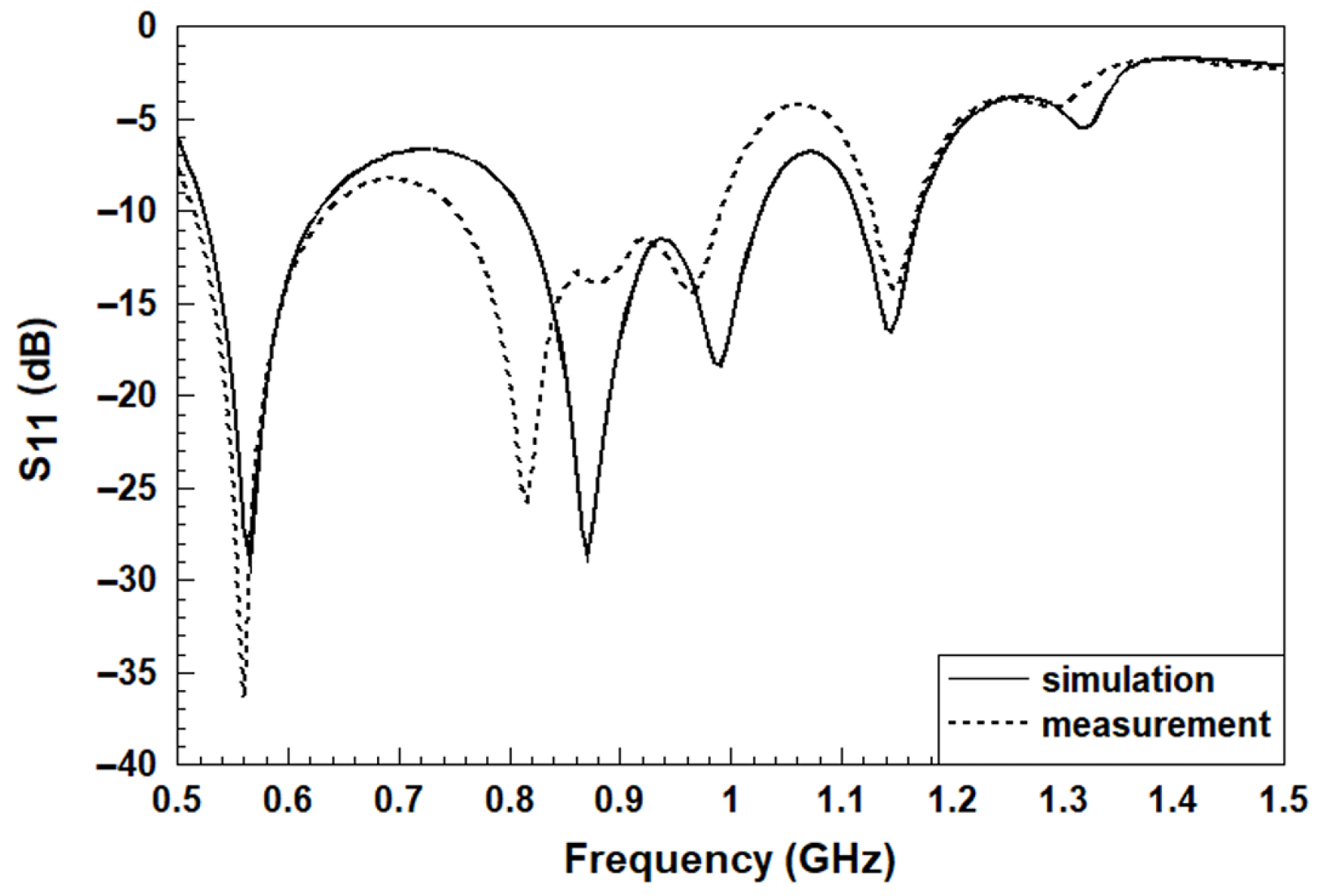
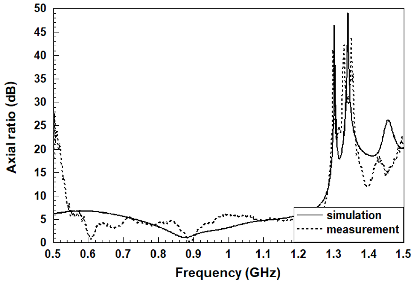
11 mode, thereby achieving circularly polarized radiation characteristics. The measured axial ratio below 3 dB indicates that excellent circular polarization is achieved over the 860–920 MHz range. By adopting a more relaxed criterion of an axial ratio below 6 dB, the operating bandwidth can be further extended to 560–985 MHz. Furthermore, to enhance the mechanical robustness of the RFID ground antenna embedded within the floor mat, the design intentionally avoids adopting an air-filled slot antenna structure [
9], which could be easily damaged under repeated impact from marathon runners. This paper proposed a novel architecture with physical multilayer configuration (FR4–acrylic–FR4). The issue of runners stepping on the mat has been resolved, while the antenna efficiency has also been significantly improved due to a physical intermediate layer. Thus, a compound structure is introduced to enhance mechanical robustness against runner impact while simultaneously improving antenna efficiency. In addition, the feeding network is located at the bottom layer of the antenna structure. In addition, the UHF RFID frequency allocation varies across regions due to local regulatory standards. In Europe, RFID systems typically operate within 865–868 MHz, while in the United States, the standard operating band is 902–928 MHz. In China, UHF RFID is allocated to the 920–925 MHz range, and in Japan, the frequency range extends from approximately 916.8 MHz to 923.4 MHz. Considering these regional differences and to ensure compatibility and broader applicability, this study adopts a UHF operating bandwidth of 860–960 MHz for antenna design and evaluation.
The architecture of the paper is organized as follows:
Section 2 presents the detailed antenna design and its corresponding theoretical analyses and simulated verifications.
Section 3 provides details on the experimental results and their discussion.
Section 4 concludes the paper. Finally,
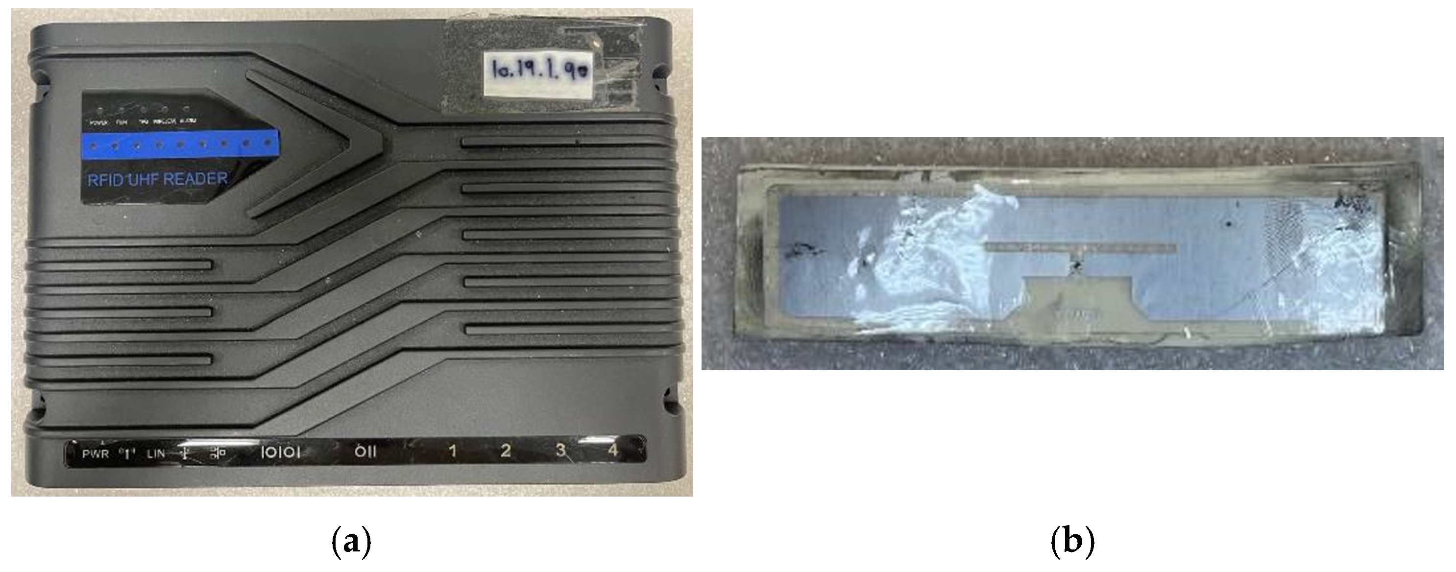
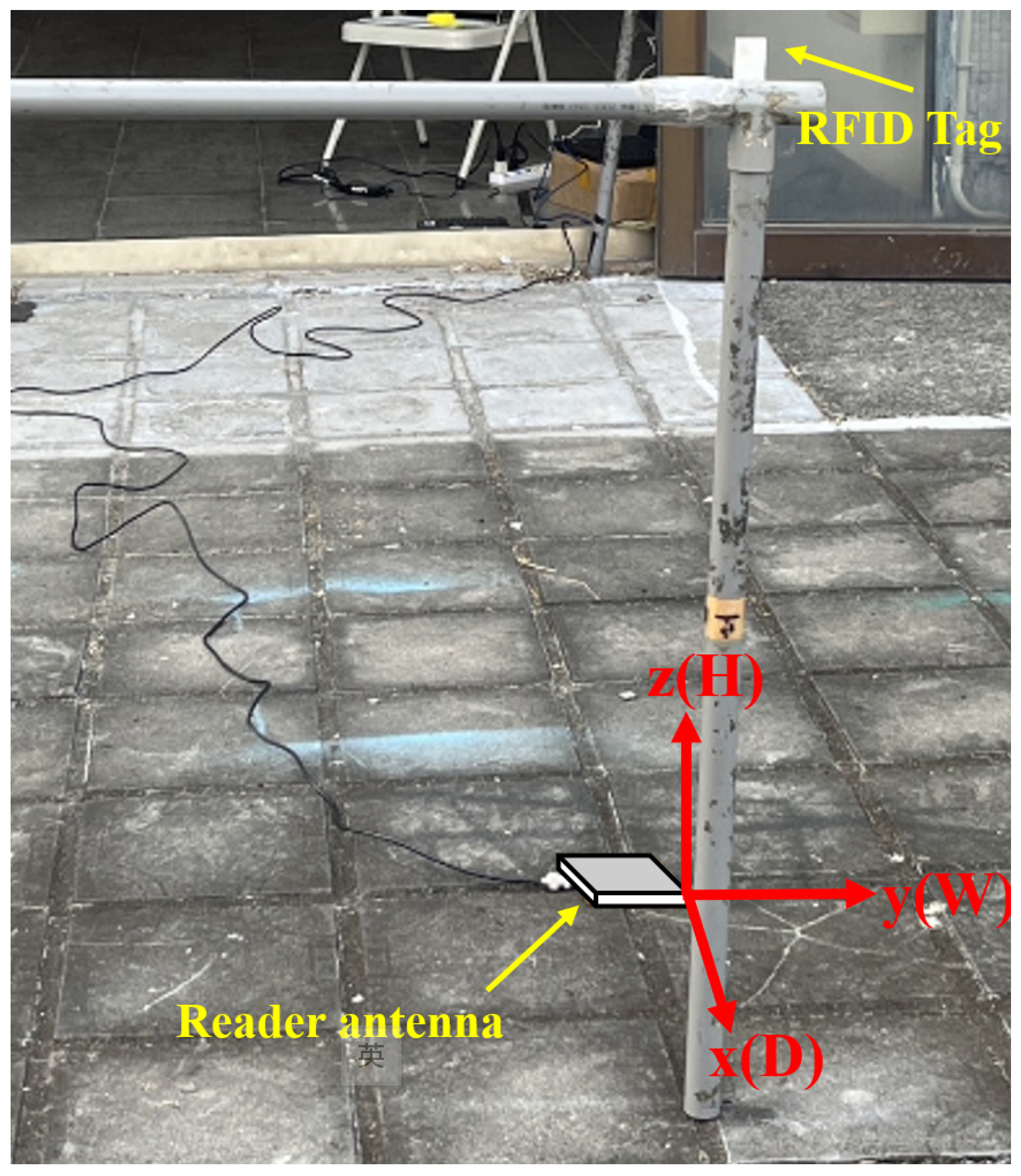
Appendix A compares the measured read distance with the commercial antenna reader.
2. Slotted Ground Choke Reader Antenna with Circular Polarization
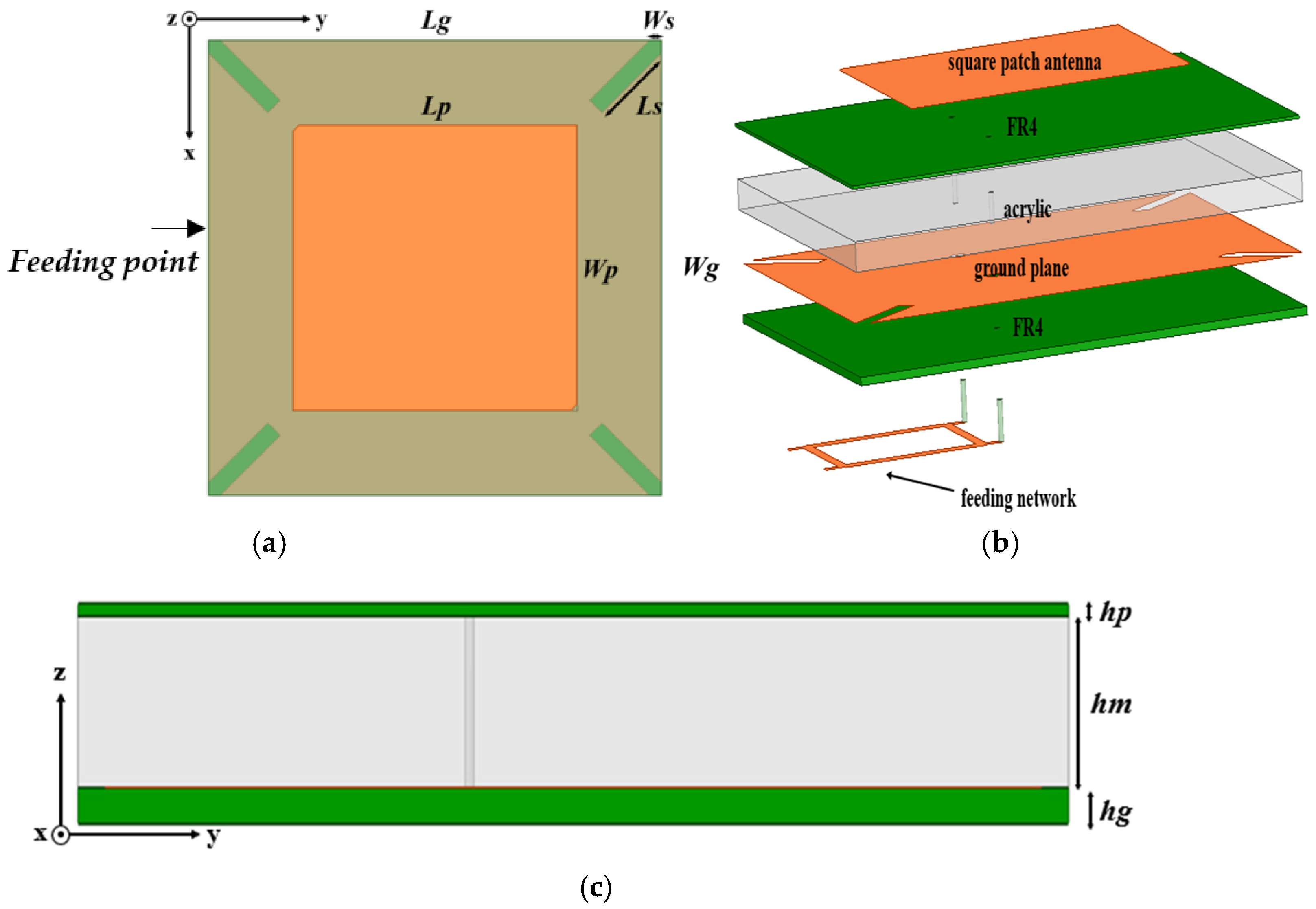
The RFID reader antenna with low-backward radiation is fabricated in a 3-layer physical stacked configuration (FR4–acrylic–FR4) to form a multilayer square patch antenna, which has the dielectric constants of 4.4, 2.8, and 4.4, respectively. The antenna architecture is illustrated in
Figure 1, with a branch-line coupler feeding network at the bottom layer to excite equal amplitude and different phase of 90° for circular polarization. Instead of an all FR4-layer structure, the material of acrylic is utilized in the intermediate layer to lower the tangent loss and then improve the overall radiation efficiency [
13]. According to Poynting’s theorem, power dissipation can be expressed as:
where
are the permittivity of the material and free space, respectively, while
μ is the permeability of the material.
Equation (2) shows that a minimized
can improve power loss, which, in turn, increases overall radiation efficiency. The loss tangent of acrylic material is approximately 0.017, which is slightly lower than that of FR4. Therefore, the FR4–acrylic–FR4 structure is adopted. The effective permittivity of the composite multilayer structure can be obtained by [
14]:
Based on Equation (3), the compound permittivity is around 2.898, which is lower than that of all FR4 layers. Replacing the intermediate layer of FR4 in acrylic reduces the loss tangent within the dielectric layer of the patch antenna in the cavity model, thereby enhancing its efficiency.
Reference [
13] introduces the concept of the effective dielectric constant (
). Since the electric field lines from the patch antenna propagate to the ground plane through both air and the dielectric substrate, the resulting discontinuous field lines can be treated as a strip line operating within a material characterized by an effective dielectric constant. The electric field is thus approximated as a continuous field. For the case where W/h ≥ 1, the effective dielectric constant
can be approximately calculated as follows:
According to Equation (4), the physical length L′ required for the patch antenna to radiate can be calculated as:
where
is the relative dielectric constant of the substrate, and
are the permittivity and permeability of free space, respectively. However, due to the edge effects arising from the propagation of the electric field through both air and the substrate, the electric length of the field lines within the substrate becomes longer than the actual physical length. Therefore, it is necessary to apply corrections to the physical length using the effective dielectric constant and corresponding formulas. The change in length caused by the edge effects is given by the following expression:
The values of the compound substrate dielectric constant (2.898) calculated above are then substituted into Equations (4)–(6) as the initial parameters for the antenna, followed by parameter investigation and optimization.
In the implementation, the acrylic middle layer was realized by potting the material between the upper and lower FR4 layers. During the process, a mold was used to maintain the desired dimensions, and the assembly was allowed to rest and cure, ensuring that the final dimensions closely matched those parameters used in the simulations. To prevent the antenna’s overall thickness from causing injury to runners due to excessive height when stepping on the mat, the total antenna thickness is limited to a maximum of 10 mm. For manufacturability, the substrate thickness
hp is set to 0.4 mm. To reduce the volume of the FR4 substrate, which exhibits a relatively high loss tangent, within the cavity structure, acrylic material with a lower loss tangent is employed to fill the remaining height
hm, set at 6 mm. This approach effectively reduces the overall internal loss of the cavity. Including the ground plane, the total antenna thickness is 8 mm. Detailed geometrical parameters are given in
Table 1 to the illustration in
Figure 1, which were obtained from the complete antenna design for circular polarization.
2.1. Branch-Line Feeding Network
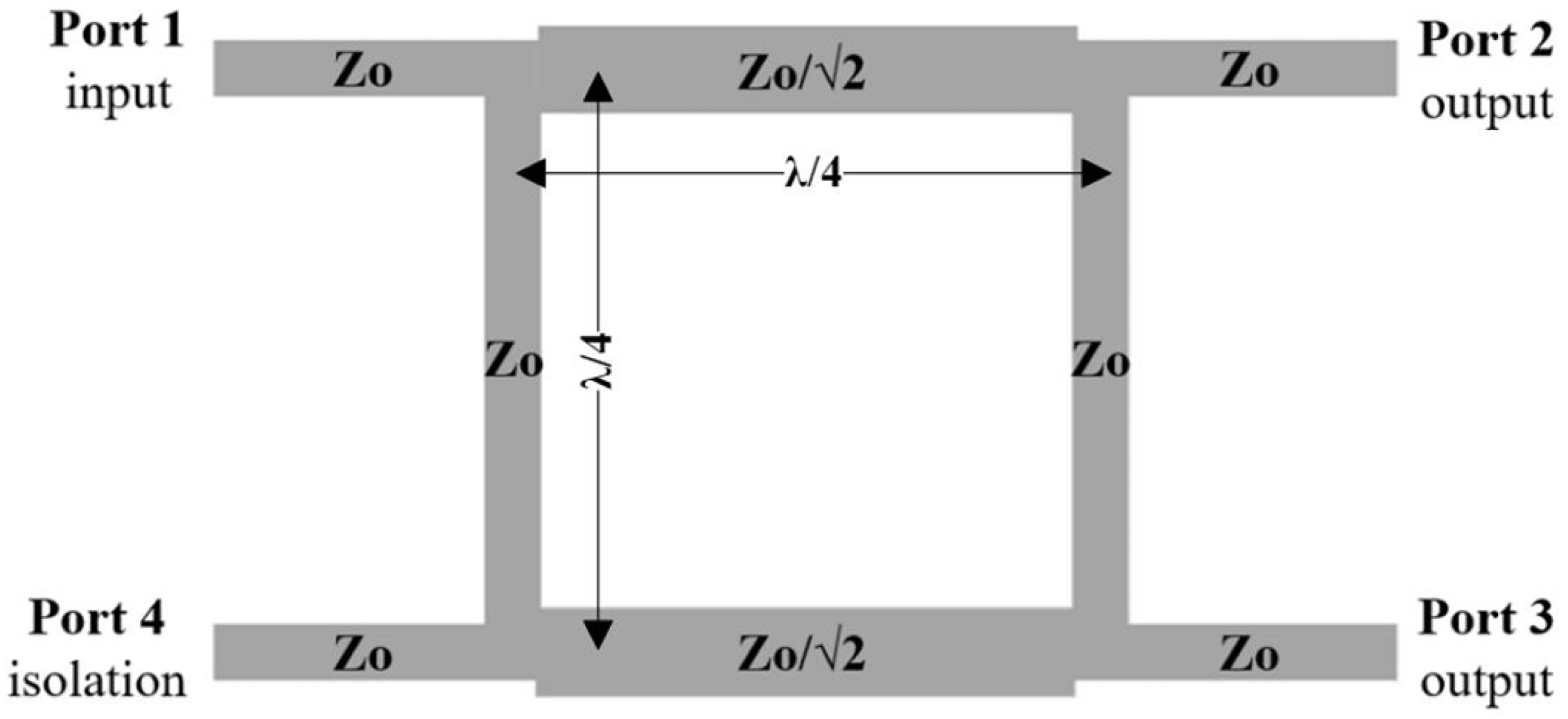
To achieve circular polarization characteristics in a square patch antenna, two excitation sources with equal magnitude and a 90° phase difference can be used. This feeding method enables the antenna to support two orthogonal modes of equal amplitude, thereby generating circular polarization. A branch-line coupler is utilized to generate two excitation signals with equal amplitude and a 90° phase difference through a single input port. This coupler serves as the input feeding network for the square patch antenna, as illustrated in
Figure 2. The signal is fed into Port 1, and through impedance matching of the microstrip lines and the phase shift introduced by quarter-wavelength transmission lines, the input signal is equally divided in power and outputs two signals with a 90° phase difference at Port 2 and Port 3. Port 4 functions as the isolated port, which is terminated by a 50 ohm resistor.
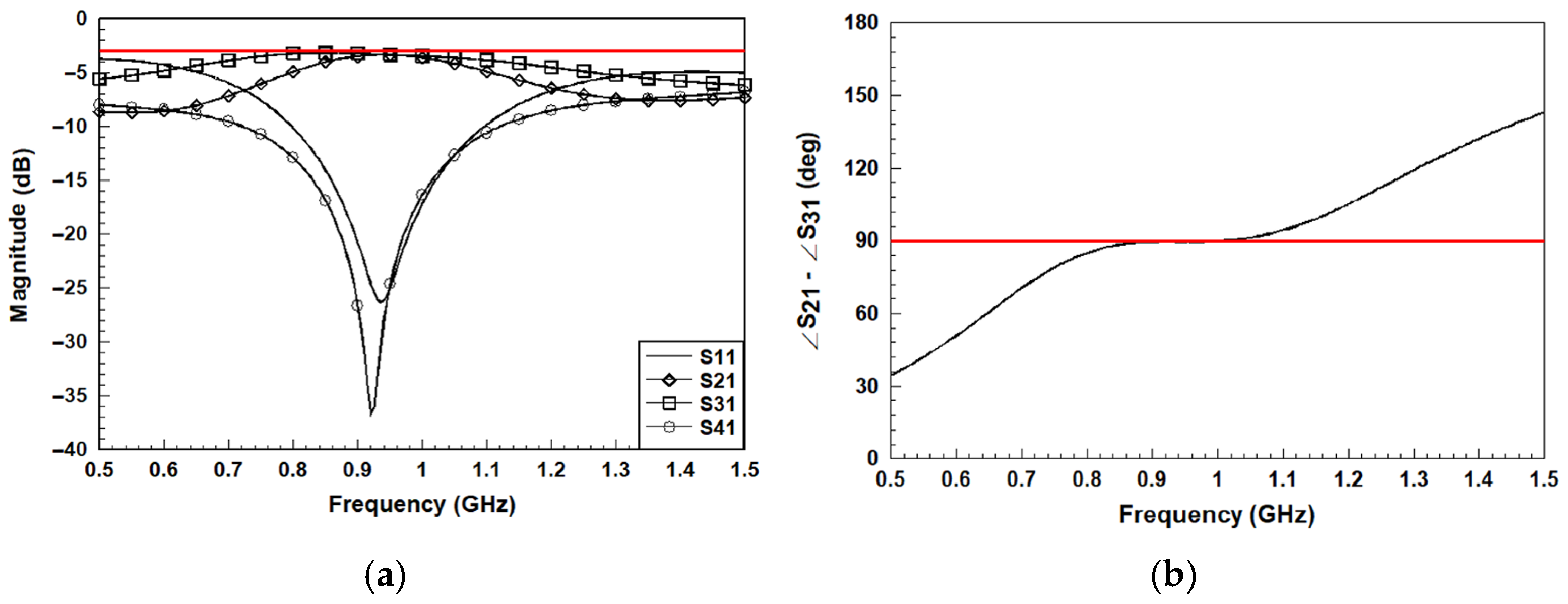
Figure 3 shows the simulated S parameters and phase difference at output ports. The branch-line coupler is designed using FR4 as the substrate (ε
r = 4.4, tan δ = 0.02, h = 1.6 mm). Simulation results show that within the operating band, output ports 2 and 3 exhibit equal power division of approximately −3 dB and a 90-degree phase difference, while the isolation port (port 4) maintains isolation better than −30 dB. This indicates that the branch-line coupler can function properly within the required 860–960 MHz band. At the center frequency of 910 MHz, the design achieves good impedance matching and nearly equal power splitting, which ensures its suitability for exciting the patch antenna to operate in the TM10 and TM01 modes.
The difference in frequency response between S21 and S31 of the branch-line coupler is primarily due to the fact that the quarter-wavelength transmission lines are designed for a specific center frequency. As the frequency deviates from this design point, variations occur at different output ports. Moreover, in composite structures, impedance mismatches are more likely to arise at frequencies outside the intended operating band, thereby reducing the effective bandwidth. Nevertheless, the resulting bandwidth still exceeds the requirements of the RFID frequency band.
To further verify the circular polarization characteristics, a branch-line coupler is employed as the feeding circuit to generate two orthogonal modes, enabling the square pate antenna to exhibit circular polarization. This configuration allows the antenna to achieve a wider circular polarization bandwidth in the direction of maximum radiation (+z direction).
Figure 4 shows the time-varying current density distribution of the square patch antenna, illustrating the evolution of surface currents over time, which indicates a right-hand circular polarization (RHCP) pattern.
2.2. Low-Backward Radiation Verification
In contrast to conventional patch antennas, the second-layer metallic ground plane, as shown in
Figure 1b, incorporates the slotted ground choke technique to achieve low-backward radiation for RFID floor mat antenna applications [
5,
6,
10,
11,
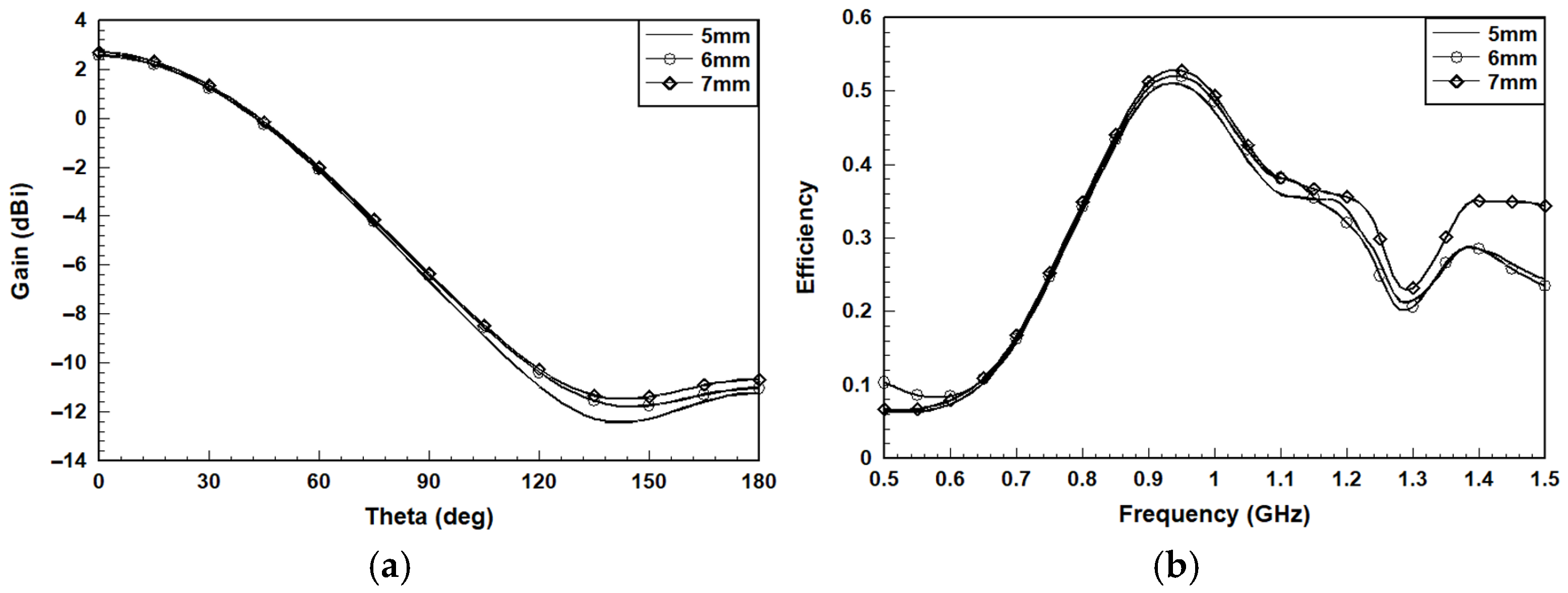
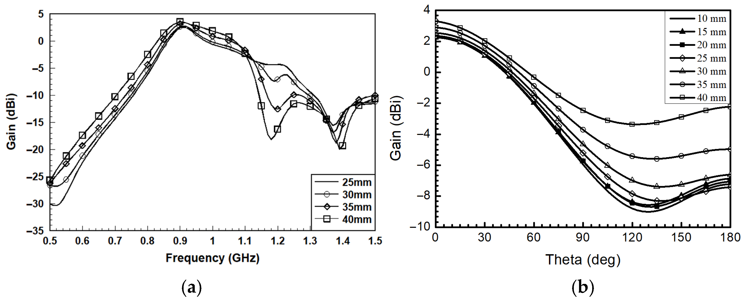
12]. The adoption of slot-based structures in antennas effectively reduces back radiation, which is particularly advantageous for floor-embedded reader antennas. This reduction in back radiation primarily stems from the inherent radiation mechanism of slot antennas, where the electromagnetic energy is radiated through openings in the ground plane rather than directly from protruding conductive elements. As a result, the ground plane itself serves as a shielding layer, significantly attenuating undesired radiation toward the back side. Furthermore, by carefully designing the shape, dimensions, and placement of the slots, the surface current distribution on the ground plane can be precisely controlled. This optimization confines the currents near the slots and away from the edges of the ground plane, thereby suppressing edge diffraction and further lowering back radiation. Techniques such as the slotted ground choke can be employed to enhance this effect by disrupting parasitic surface currents that would otherwise contribute to unwanted radiation. Therefore, by adjusting the dimensions of the slots on the ground plane, the surface current distribution can be effectively modified. This technique enhances the antenna’s overall performance in terms of back radiation suppression. Therefore, by varying the slot width
Ws on the ground plane, it is observed that changes to this parameter have minimal impact on the S-parameters, directivity, and circular polarization bandwidth. However, as the
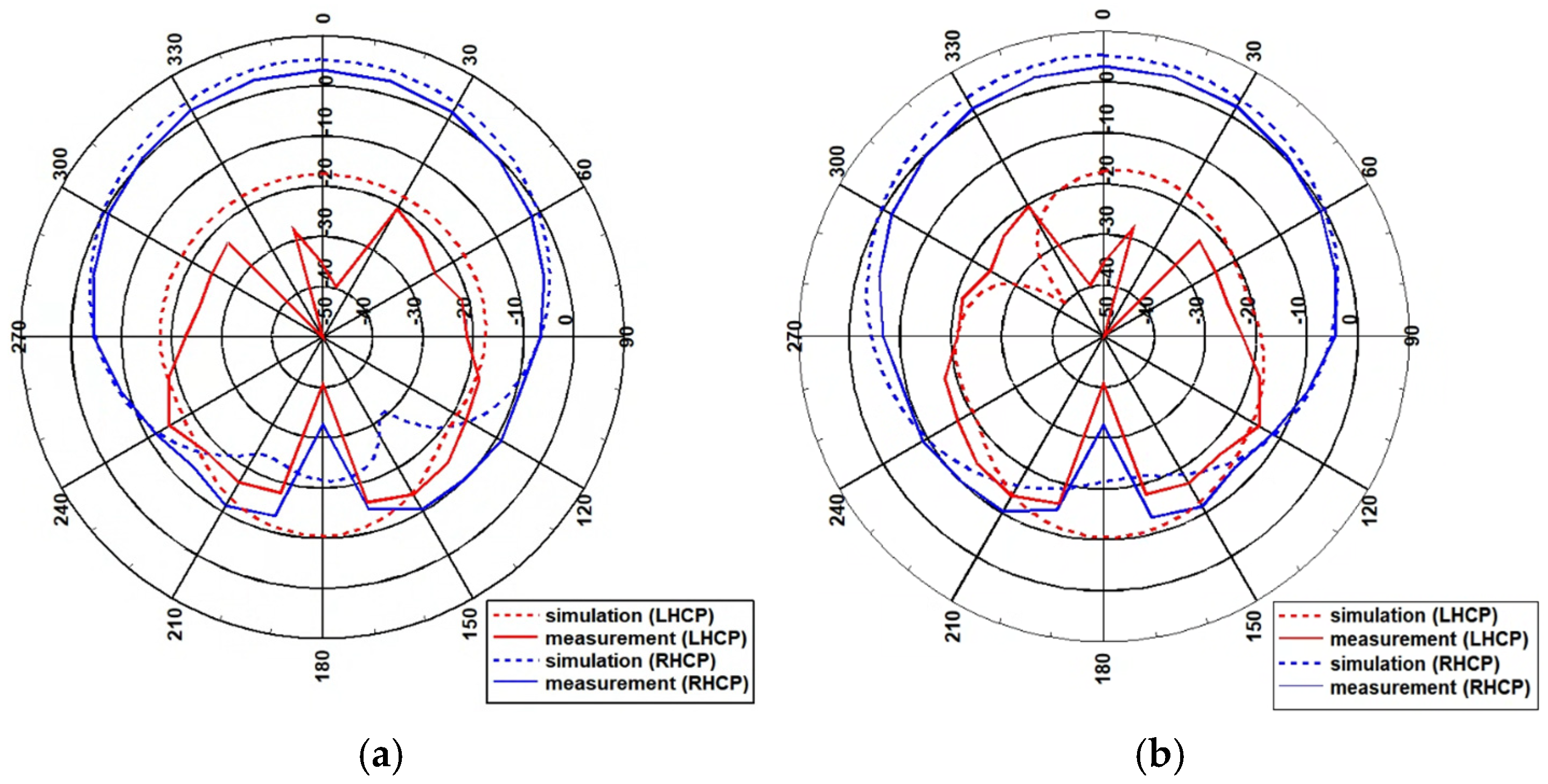
Ws decreases, the magnitude of back radiation in the −z direction also reduces, as shown in
Figure 5a. This leads to an improvement in the antenna’s front-to-back ratio, which helps minimize back radiation and thereby reduces the likelihood of read failures caused by multipath interference. Nonetheless, this improvement comes at the cost of a slight decrease in radiation efficiency, illustrated in
Figure 5b.
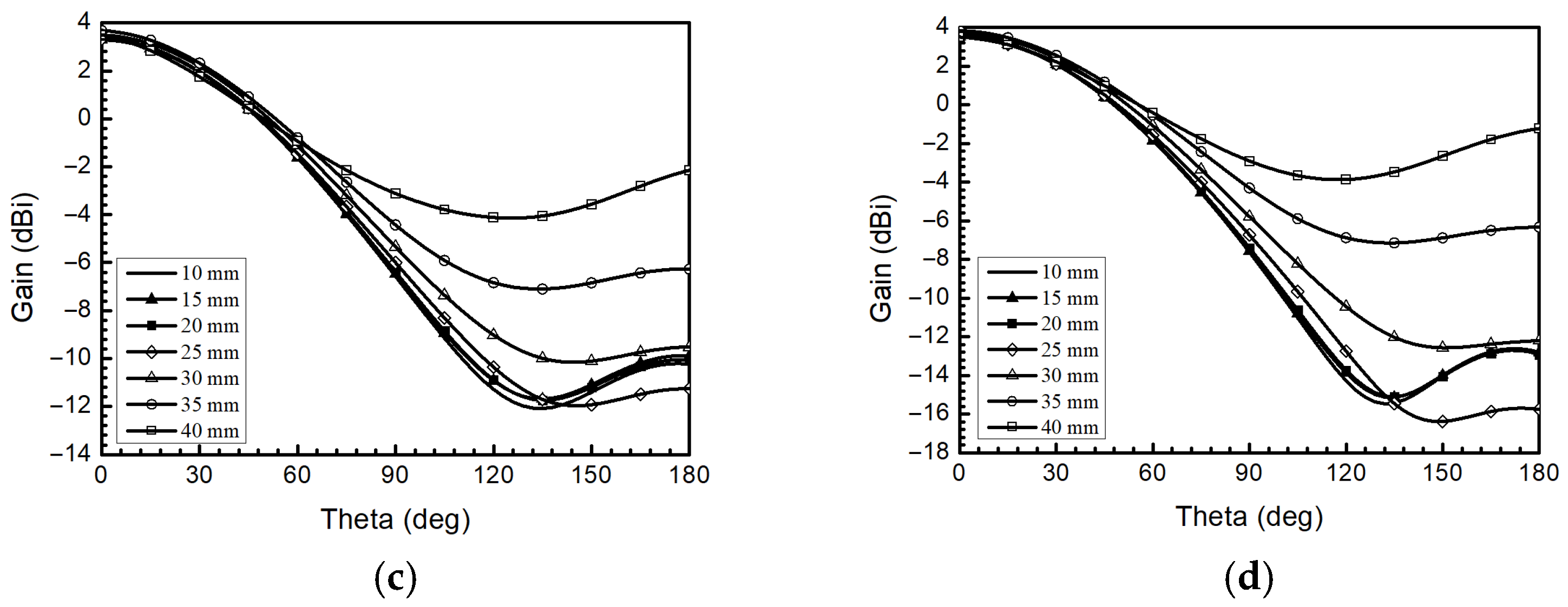
The variation of the parameter (
Ls) exhibits negligible influence on the antenna’s S-parameters; however, it contributes to a slight upward shift in the center frequency of the circular polarization bandwidth. As
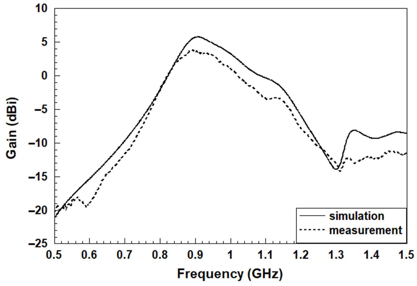
Ls increases, a moderate degradation in directivity is observed, accompanied by an improvement in radiation efficiency, which results in a net increase in overall gain, as illustrated in
Figure 6a. Furthermore, under certain conditions, the gain response across the operating frequency band becomes more uniform, effectively mitigating the gain roll-off observed from 860 MHz and 960 MHz. This flattening of the gain curve enhances frequency stability. Nevertheless, an increase in
Ls also leads to elevated back radiation levels, as depicted in
Figure 6b, c, and d at 860 MHz, 910 MHz, and 960 MHz, respectively, thereby reducing the front-to-back ratio. From the simulation results, it can be observed that when
Ls is reduced below 30 mm, the improvement in backward radiation suppression becomes limited, while the antenna gain slightly decreases. Therefore, in the antenna design, a moderate value of
Ls is selected to achieve substantial backward radiation suppression while maintaining a reasonable antenna gain. This trade-off highlights the need for an optimization between gain enhancement and the suppression of undesired back radiation.
2.3. Efficiency Consideration
In addition to dual excitation and slot ground choke for the proposed RFID antenna with circular polarization and low-backward radiation, respectively, efficiency is another issue to extend reading distance of the ground mat reader antenna. To address the issue of low efficiency, a multi-layered architecture is proposed as an effective solution to enhance overall performance. The radiation efficiency (
) of an antenna is related to its radiated power (
), which can be expressed as:
where
represents the radiated power of the antenna,
denotes the power delivered to the antenna after accounting for matching losses,
is defined as the radiation efficiency, and
is defined as the reflection efficiency of the antenna, representing the efficiency loss due to impedance mismatch. According to (7) and (8), enhancing the radiated power is proposed as a solution to improve both radiation efficiency and antenna gain. Thus, to reduce the loss tangent (tan δ) of the intermediate dielectric layer, acrylic material was adopted as the filler for the intermediate layer, as shown in
Figure 1b. The overall substrate can be significantly reduced by a lower equivalent dielectric constant of 2.898 in this the multilayer structure.
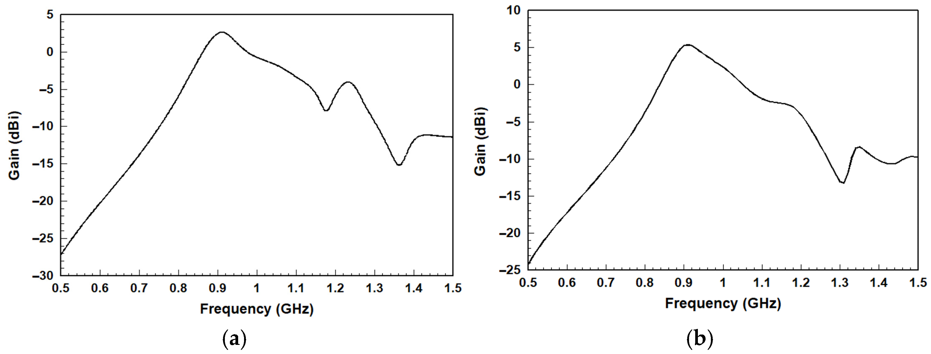
To verify that the physical multilayer antenna (FR4–acrylic–FR4) offers advantages in efficiency and gain compared to a fully solid FR4 structure, we first matched the input of both configurations to the desired frequency band in order to minimize efficiency loss caused by impedance mismatch (decrease
). As shown in
Figure 7, after replacing the intermediate dielectric layer with acrylic material, which has a lower loss tangent, the efficiency improved significantly. The entire efficiency is boosted from an initial value of 0.5 to approximately 0.8–0.9. Furthermore, assuming that the antenna’s directivity remains largely unchanged, it can be inferred that the antenna gain is likely to improve. It is worth mentioning that the simulated efficiency increases significantly at 1.35 GHz. However, the gain improvement is not as prominent. The frequency point at 1.35 GHz is outside the main operating frequency band, resulting in poor input impedance matching, which in turn limits the gain. Although the efficiency is higher at 1.35 GHz, the gain remains relatively low.
Figure 8 depicts the comparison of gains between the two structures. The corresponding antenna gain also shows a significant improvement. Therefore, by adopting an FR4–acrylic–FR4 configuration, the overall effective dielectric constant is reduced, and with appropriate parameter design, the radiation efficiency of the antenna can be improved.
4. Conclusions
This paper presents the design of a ground mat RFID reader antenna for sports timing systems, with a focus on achieving high front-to-back ratio and circular polarization to effectively reduce missed reads caused by multipath interference. Unlike previous studies that utilized air as the dielectric medium, the proposed design employs a multilayer square patch structure using acrylic dielectric material. This approach enhances mechanical robustness against foot traffic while minimizing the risk of injury due to uneven height differences. Overall, the proposed antenna design demonstrates a balanced improvement over existing solutions by simultaneously achieving compact dimensions, enhanced circularly polarized gain, and reduced back radiation. Additionally, in order to improve the alignment between theoretical predictions and practical measurements, a correction factor is applied to the estimated read range model. Outdoor measurements were conducted in an outdoor environment to emulate practical application scenarios. The performance of the proposed antenna was comprehensively evaluated via theoretical analysis, full-wave electromagnetic simulations, prototype implementation, and field testing under actual marathon event conditions. The measured results demonstrate that the design meets the expected performance and is well suited for deployment in practical sports timing applications.

