SPARSE-OTFS-Net: A Sparse Robust OTFS Signal Detection Algorithm for 6G Ubiquitous Coverage
Abstract
1. Introduction
- (1)
- Ubiquitous Connectivity: Demands seamless air–space–ground–sea coverage. The resulting channels are highly heterogeneous—e.g., high-speed rail channels exhibit Doppler spreads up to 1 kHz, and satellite links experience delay spreads exceeding 10 ms. Traditional detectors struggle to balance dynamics and accuracy; ref. [1] shows that 5G algorithms degrade to a BER of 10−2 at 1000 km/h.
- (2)
- Ultra-Dense Deployment: The 6G network aims for an area-level deployment target of 107 devices per square kilometer. However, during peak hours, a single base station must simultaneously schedule and transmit data for hundreds of users, leading to significantly intensified pilot contamination and multi-user interference. Field measurement data in [2] demonstrate that when 1024 users access concurrently, the Error Vector Magnitude (EVM) of conventional MMSE detection deteriorates to 18%, far exceeding the 8% threshold typically required by communication standards.
- (3)
- Physical–Digital Symbiosis: Requires joint optimization of physical channels and their digital-twin models, but existing approaches cannot achieve millisecond-level synchronization—ref. [3] shows that latency jitter must remain below 0.1 ms.
- (1)
- The Least Squares (LS)-based channel estimation algorithm [4] achieves rapid estimation by constructing a pilot matrix and directly computing its pseudo-inverse, with a computational complexity of O(P3 + P2MN). It is well-suited for low-interference environments. When the signal-to-noise ratio exceeds 20 dB, the normalized mean square error (NMSE) can reach −15 dB, and detection latency is as low as 0.5 ms. However, the method exhibits several significant drawbacks: pilot contamination degrades the error-vector magnitude (EVM) to 18% in multi-user scenarios; Doppler spreads exceeding 500 Hz increase the estimation error by 10 dB; and multipath components with similar power cannot be resolved, as the resolution is limited to 1/Ts;
- (2)
- The Minimum Mean Square Error (MMSE) algorithm [5,6] performs channel estimation by exploiting the statistical properties of noise and multipath interference, exhibiting excellent noise-robustness with an NMSE as low as −20 dB. Nevertheless, the method suffers from notable limitations: in multipath resolution, its delay resolution can only reach half of the conventional grid spacing, failing to achieve super-resolution estimation; and in dynamic channel tracking, performance degrades by 40% when the frequency offset exceeds 500 Hz;
- (3)
- The 3D Simultaneous Orthogonal Matching Pursuit (3D-SOMP) algorithm [7] significantly enhances OTFS massive MIMO channel-estimation accuracy by leveraging a three-dimensional sparse model spanning delay, Doppler, and angle. With 128 antennas, it reduces pilot overhead by 40% and achieves an NMSE of −22 dB, while regularized screening effectively mitigates fractional-Doppler effects. However, its practical deployment is constrained by limited dynamic adaptability and hardware implementation bottlenecks, restricting its applicability in real-time communication scenarios;
- (4)
- The Sparse Bayesian Learning with damped Least Squares Minimum Residual (SBL-d-LSMR) algorithm [8] achieves high-precision fractional-Doppler estimation by integrating a Basis Expansion Model (BEM) with sparsity-driven optimization. With only 15% pilot overhead, it attains an NMSE of −22 dB and a BER as low as 10−5 in 120 km/h vehicular networks. However, its performance depends on the channel-sparsity assumption; in dense multipath environments, estimation accuracy decreases by 30%. In addition, 20–30 SBL iterations are required for convergence, resulting in limited real-time capability; dynamic Doppler adaptability is constrained; hardware implementation increases power consumption by 25%; and the algorithm exhibits high parameter sensitivity. These limitations restrict its applicability in more complex scenarios;
- (5)
- Atomic Norm Minimization (ANM) off-grid channel estimation [9] overcomes the limitations of conventional discrete-grid approaches by employing a continuous-domain sparse-recovery framework. The method models delay-Doppler parameters as continuous variables and achieves super-resolution through atomic norm minimization, providing a ten-fold improvement in resolution over traditional techniques and reducing delay error to below 0.1 µs. Nevertheless, it suffers from high computational complexity, limited sensitivity to weak multipath components, and significant performance degradation in multi-user scenarios;
- (6)
- The CNN (Convolutional Neural Network)-based OTFS detector [10] employs multi-scale convolutional kernels to extract local delay-Doppler domain features, enhances sparsity through Rectified Linear Unit (ReLU) activations, and produces symbol estimates via fully connected layers. At 15 dB SNR, it achieves a BER of 3 × 10⁻⁵ with a detection latency of only 1.2 ms, representing a significant improvement over conventional OMP algorithms. Nevertheless, the approach has notable limitations: with a fixed training set, the error-vector magnitude degrades to 18% in multi-user scenarios, indicating insufficient adaptability to dynamic interference patterns;
- (7)
- The GNN (Graph Neural Network)-based OTFS resource-allocation algorithm [11] introduces an innovative dynamic-attributed graph model that maps delay-Doppler space resource units to graph vertices while representing inter-user interference relationships as dynamic edges. In scenarios with 1024 users, it achieves a latency of only 0.6 ms and suppresses multi-user interference by −22 dB. However, the algorithm has two major limitations: it relies on prior channel state information (CSI), with performance decreasing by 30% when CSI error exceeds 10%, and frequent retuning is required under severe Doppler spreads;
- (8)
- The Transformer-OTFS algorithm [12] introduces a novel Gated Multi-Head Self-Attention (G-MHSA) mechanism to capture global context in the delay-Doppler domain. By integrating positional encoding to accurately preserve spatiotemporal signal features, it achieves a bit-error rate of 5 × 10⁻⁷ at 15 dB SNR and suppresses multi-user interference by −22 dB, outperforming existing approaches. However, the algorithm requires 50,000 training samples, which is five times the data demand of CNN-based methods;
- (9)
- Model-Agnostic Meta-Learning (MAML) [13] enables rapid adaptation by creating a dynamic initialization pool that supports instantaneous switching among typical scenarios, such as high-speed rail (500 km/h) and UAV links. It achieves an NMSE of −28 dB with only 50 pilot symbols, reducing pilot overhead to 3%. A notable limitation is that the meta-task generalization capability decreases by 40% under severe Doppler spread.
2. SPARSE-OTFS-Net Model Construction
2.1. Overall Model Structure
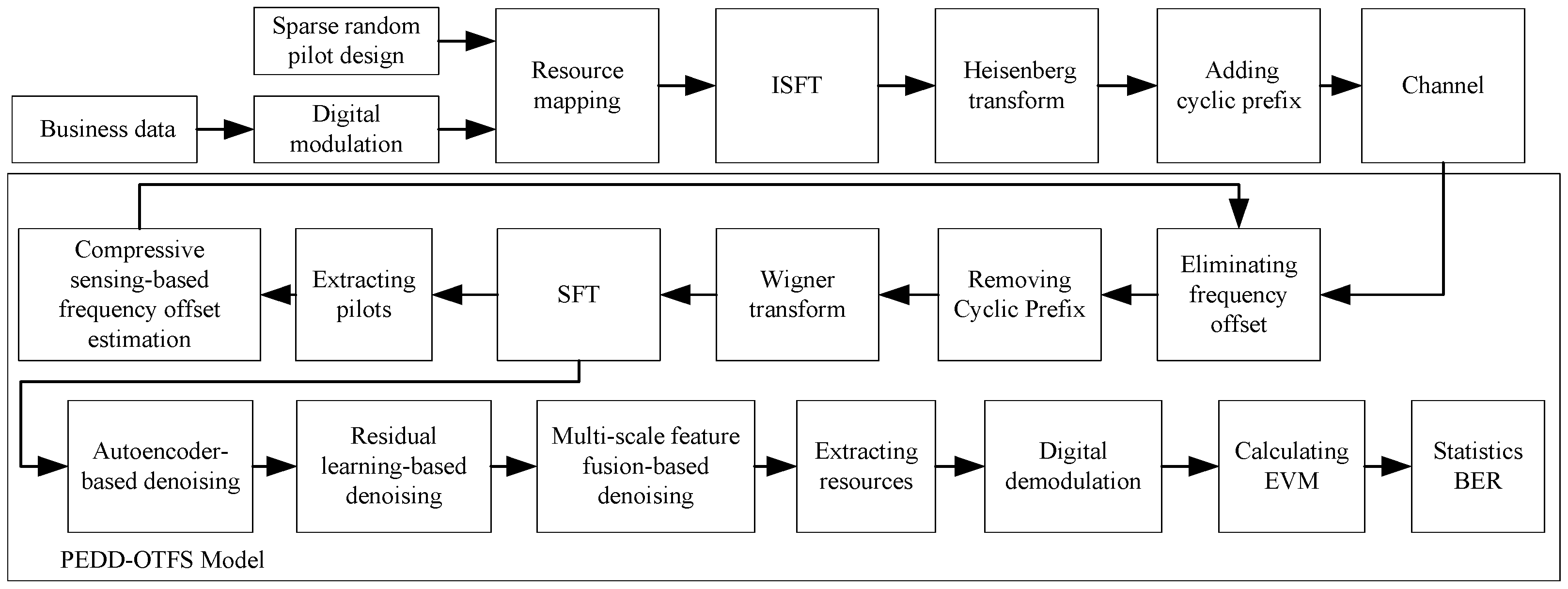
- The autoencoder module extracts the sparse features of the DD domain signal through a deep convolutional network. This effectively suppresses multipath interference, co-channel/inter-channel interference, and additive white Gaussian noise (AWGN), significantly improving signal quality in low signal-to-noise ratio (SNR) environments;
- The residual learning network models the residual features of separable interference through a gating mechanism, focusing on eliminating strong multipath interference and intermittent co-channel interference;
- The multi-scale fusion mechanism combines features at different resolutions through a parallel multi-path architecture, significantly enhancing the model’s robustness against mixed interference (including co-channel, inter-channel, multipath, and cross-system interference).
2.2. SPARSE-OTFS-Net Signal Parsing Algorithm
| Algorithm 1: SPARSE-OTFS-Net Signal Parsing |
| Input: Received signal matrix Y ∈ ℂ^(M × N) (M delay dimension, N Doppler dimension) Dynamic pilot positions S (deep learning-generated) Noise power σ2 Output: Parsed clean signal Ŷ_final 1://Sparse random pilot design Generate pilot symbols: p_k = complex_pilot_symbol();//QPSK (Quadrature Phase Shift Keying)/QAM (Quadrature Amplitude Modulation) modulation Layout pilots dynamically: For each position (k, l): if (k, l) ∈ S: X[k][l] = p_k else: X[k][l] = 0 Synchronization mechanism: Y_p = matching_pursuit(Y); //Extract pilots with sparse sensing compensate_delay(≤0.1 Ts); //Time delay compensation compensate_doppler(≤20 Hz); //Doppler frequency offset if (doppler > 500 Hz) increase_pilot_ratio(10%);//Adaptive for high Doppler 2://Compressive sensing frequency offset estimation y = vectorize(Y); // Vectorize received signal D = []; // Initialize dictionary matrix for (i = 1 to L): D.append(SUG(Δf_i) * conjugate_transpose(U) * P);//Build Φ(Δf_i), SUG: Sparse Unitary Group //OMP(Orthogonal Matching Pursuit) frequency offset estimation r = y_p; //Initialize residual I = {}; //Initialize support set while (norm(r) ≥ σ_t): i_t = argmax_i(|dot_product(D[:,i], r)|/norm(D[:,i]));//Find best match I = I ∪ {i_t}; //Update support set α = least_squares(D[:,I], y_p);//Solve least squares r = y_p—D[:,I] * α; //Update residual Δf_hat = Δf_i_L; //Estimated frequency offset 3://Frequency offset compensation G = diag_matrix(exp(j*2*π*Δf_hat*(0:N-1)/N));//Compensation matrix Y_comp = inverse(G) * Y; //Compensate frequency offset 4://Joint denoising mechanism //Autoencoder denoising Ŷ_ae = autoencoder(Y_comp); //Apply autoencoder //Encoder: ReLU(conv_layer(Z, W_e, b_e)) //Decoder: ReLU(deconv_layer(Ŷ, W_d, b_d)) //Loss: ‖Y—Ŷ_ae‖22 //Residual learning denoising noise_map = resnet(Ŷ_ae); //Learn noise residual Ŷ_res = Ŷ_ae—noise_map; //Subtract noise //Loss: ‖N—noise_map‖22 + λ * ‖noise_map‖1 //Multi-scale feature fusion F1 = conv3 × 3(Ŷ_res); //3 × 3 convolution F2 = conv5 × 5(Ŷ_res); //5 × 5 convolution F3 = conv7 × 7(Ŷ_res); //7 × 7 convolution Σ = covariance_matrix(F1, F2, F3);//Compute covariance matrix α, β, γ = adaptive_weights(Σ); //Compute dynamic weights Ŷ_final = α * F1 + β * upsample(F2) + γ * upsample(F3);//Fusion return Ŷ_final; |
3. Core Module Design
3.1. Sparse Random Pilot Signal Design
- (1)
- Pilot detection: At the receiver, compressive sensing matching pursuit is applied to extract pilots from the random locations S. Correlation peak detection, based on the known amplitude/phase signature p1(k,l), resolves the synchronization challenge caused by non-fixed pilot positions;
- (2)
- Joint timing–frequency calibration: Using the estimated pilot locations , an interpolation-based phase-locked loop (PLL) compensates for both timing offset (error ≤ 0.1 Ts) and Doppler shift (error ≤ 20 Hz);
- (3)
- Dynamic feedback optimization: An online learning module continuously adapts the pilot density across the M × N grid, balancing signaling overhead against synchronization robustness. For instance, the pilot ratio is increased to 10% in high-Doppler scenarios.
3.2. Received Signal Model
- is the diagonal matrix representing the frequency offset, given by ;
- is the N-point Discrete Fourier Transform (DFT) matrix;
- W is the additive white Gaussian noise.
3.3. Compressive Sensing-Based Frequency Offset Estimation
- Select Atom: ;
- Update Support Set: ;
- Least Squares Estimation: ;
- Update Estimation Error: .
3.4. Autoencoder Denoising
- Encoder
- Decoder
- Forward pass: the noisy input is first fed into the encoder—a stack of convolution layers with ReLU activations—yielding a low-dimensional latent feature . is then passed through the decoder, composed of transposed convolutions and ReLU activations, to produce the reconstructed signal ;
- Compute the loss ;
- Back-propagation: compute the gradients 〖∇L〗 _recon of the loss with respect to the weights W_e^((Ɩ)) and biases b_e^((Ɩ)) using the chain rule, employing the derivative of the ReLU activations.
3.5. Residual Learning for Denoising Under Non-Gaussian Noise Challenges
- Forward pass: the noisy input Y′ is forwarded through the residual network to yield a noise estimate R(Y′);
- Compute the loss ;
- Back-propagation: for gradient computation, the ‖·‖_2^2 term employs the standard L2-norm(Least Squares Norm) derivative, whereas the ‖·‖_1 term is handled via the sub-gradient method.
3.6. Multi-Scale Feature Fusion Denoising
- Multi-branch Convolution
- Adaptive Fusion
- (1)
- Data preparation: assemble the dataset , where denotes the noisy input and the corresponding clean target.
- (2)
- Feature extraction and fusion:
- Multi-branch convolution: the input is processed by three parallel convolutional layers to produce feature maps , , and , whose kernel sizes are 3 × 3, 5 × 5, and 7 × 7, respectively, capturing information across different frequency bands;
- Feature fusion: , where α, β, and γ are learnable weights initialized to 1;
- Final output: the fused feature is forwarded through additional layers (e.g., fully connected or convolutional) to generate the denoised signal .
- (3)
- Loss function and optimization: the loss is based on the mean squared error, i.e.,
- (4)
- Training steps
- Forward pass: compute , , , and the fused feature ;
- Loss computation: ;
- Back-propagation: gradients are applied to update the fusion weights (α, β, γ) and the convolutional kernels. The objective is to maximize the output signal-to-noise ratio; through this learning process, the weights automatically emphasize dominant signal features and suppress noise, thereby improving the overall SNR.
- (5)
- Training algorithm
4. Performance Evaluation and Simulation Analysis
4.1. Large Frequency Offset, Multipath, and Low SNR Scenario Test
- Signal bandwidth: 30.72 MHz;
- Subcarrier spacing: 30 kHz;
- Delay dimension (M): 1024;
- Doppler dimension (N): 16 (Doppler resolution: 1.876 kHz);
- Doppler shift: 1 kHz;
- Channel environment: 1024 multipath interferences with a maximum delay of 3.1 μs and a maximum multipath gain of −24.2 dB;
- Service distribution: 42 resource blocks (RBs) out of a total of 85 RBs.
4.2. Performance Evaluation in High-Speed Mobility Scenario
- Doppler estimation accuracy: ±25 Hz (approaching the Cramér–Rao lower bound);
- Bit error rate (BER): 5.0 × 10⁻⁶ (7× improvement over single-Gaussian CNN’s 3.5 × 10⁻⁵).
4.3. Multi-User Interference Scenario Test
5. Conclusions
- Large frequency offset and multipath environments (Doppler tracking error approaching 20 Hz);
- High-speed mobility at 1000 km/h (performance nearing theoretical optimum);
- Parallel access for 1024 users (achieving BER = 10−5 at SNR = 9.2 dB with multi-kernel fusion, versus 11.4 dB for single-kernel CNN, showing significant interference resistance improvement).
- Exploring the deep integration of OTFS and edge computing [17] to enhance the real-time performance of the algorithm;
- Investigating the detection methods for new transmission technologies such as NOMA (Non-Orthogonal Multiple Access)-OTFS [18] and terahertz communication;
- Strengthening the robustness verification of the algorithm in typical scenarios such as industrial dense multipath and vehicle-to-everything (V2X) communications [19];
- Promoting the standardization of complex channel models for 6G Internet of Things.
Author Contributions
Funding
Data Availability Statement
Conflicts of Interest
References
- Wei, Z.; Yuan, W.; Li, S.; Yuan, J.; Bharatula, G.; Hadani, R.; Hanzo, L. Orthogonal Time-Frequency Space Modulation: A Promising Next-Generation Waveform. IEEE Wirel. Commun. 2021, 28, 136–144. [Google Scholar] [CrossRef]
- 3GPP TR 38.901, version 17.0.0. Study on Channel Model for Frequencies from 0.5 to 100 GHz. 3rd Generation Partnership Project: Sophia Antipolis, France, 2023.
- Li, S.; Yuan, W.; Yuan, J.; Caire, G. On the Potential of Spatially-Spread Orthogonal Time Frequency Space Modulation for ISAC Transmissions. In Proceedings of the ICASSP 2022—2022 IEEE International Conference on Acoustics, Singapore, 22–27 May 2022. [Google Scholar] [CrossRef]
- Surabhi, G.D.; Chockalingam, A. Low-Complexity Linear Equalization for OTFS Modulation. IEEE Commun. Lett. 2020, 24, 330–334. [Google Scholar] [CrossRef]
- Murali, K.R.; Chockalingam, A. On OTFS Modulation for High-Doppler Fading Channels. In Proceedings of the 2018 Information Theory and Applications Workshop (ITA), San Diego, CA, USA, 11–16 February 2018; pp. 11–16. [Google Scholar] [CrossRef]
- Raviteja, P.; Phan, K.T.; Hong, Y.; Viterbo, E. Interference Cancellation and Iterative Detection for Orthogonal Time Frequency Space Modulation. IEEE Trans. Signal Process. 2020, 68, 258–272. [Google Scholar] [CrossRef]
- Shen, W.; Dai, L.; Han, S.; Chih-Lin, I.; Heath, R.W. Channel Estimation for Orthogonal Time Frequency Space (OTFS) Massive MIMO. IEEE Trans. Signal Process. 2019, 67, 4204–4217. [Google Scholar] [CrossRef]
- Yong, L.; Xue, L. Low Complexity Receiver Design for Orthogonal Time Frequency Space Systems. J. Electron. Inf. Technol. 2024, 46, 2418–2424. [Google Scholar]
- Tian, Z.; Zhang, Z.; Wang, Y. Low-complexity optimization for two-dimensional direction-of-arrival estimation via decoupled atomic norm minimization. In Proceedings of the 2017 IEEE International Conference on Acoustics, Speech and Signal Processing (ICASSP), New Orleans, LA, USA, 5–9 March 2017. [Google Scholar] [CrossRef]
- Enku, Y.K.; Bai, B.; Wan, F.; Guyo, C.U.; Tiba, I.N.; Zhang, C.; Li, S. Two-Dimensional Convolutional Neural Network-Based Signal Detection for OTFS Systems. IEEE Wireless Commun. Lett. 2021, 10, 2514–2518. [Google Scholar] [CrossRef]
- Zhang, X.; Zhang, S.; Xiao, L.; Li, S.; Jiang, T. Graph Neural Network Assisted Efficient Signal Detection for OTFS Systems. IEEE Commun. Lett. 2023, 27, 2058–2062. [Google Scholar] [CrossRef]
- Yang, H.; Zhu, J.; Sun, Y.; Ding, Z. A Transformer Based Signal Detection Method for Orthogonal Time Frequency Space Communication Systems. In Proceedings of the 024 IEEE/CIC International Conference on Communications in China (ICCC Workshops), Hangzhou, China, 7–9 August 2024. [Google Scholar] [CrossRef]
- Zhang, Z.; Duan, J.; Wang, G. Channel Estimation of IRS-OTFS Communication System with Meta-learning Algorithm. J. Electron. Inf. Technol. 2024, 46, 1353–1362. [Google Scholar] [CrossRef]
- Rasheed, O.K.; Surabhi, G.D.; Chockalingam, A. Sparse Delay-Doppler Channel Estimation in Rapidly Time-Varying Channels for Multiuser OTFS on the Uplink. In Proceedings of the IEEE 91st Vehicular Technology Conference, Antwerp, Belgium, 25–28 May 2020. [Google Scholar] [CrossRef]
- Tek, Y.I.; Dogukan, A.T.; Basar, E. Autoencoder-Based Enhanced Orthogonal Time Frequency Space Modulation. IEEE Commun. Lett. 2023, 27, 2628–2632. [Google Scholar] [CrossRef]
- Balan, S.; Joshi, S. A Study of High-Speed Railway Communication Channel Models for OTFS-Based Systems. In Proceedings of the 2024 16th International Conference on COMSNETS, Bengaluru, India, 3–7 January 2024. [Google Scholar] [CrossRef]
- Bi, J.; Cheng, X.; Yuan, H.; Niu, S.; Zhai, J. Resource Allocation and Trajectory Optimization in Unmanned Aerial Vehicle-assisted Mobile Edge Computing. In Proceedings of the 2024 IEEE International Conference on SMC, Kuching, Malaysia, 6–10 October 2024. [Google Scholar] [CrossRef]
- Chatterjee, A.; Rangamgari, V.; Tiwari, S.; Das, S.S. Nonorthogonal Multiple Access With Orthogonal Time–Frequency Space Signal Transmission. IEEE Syst. J. 2021, 15, 383–394. [Google Scholar] [CrossRef]
- Nguyen, D.C.; Ding, M.; Pathirana, P.N.; Seneviratne, A.; Li, J.; Niyato, D.; Dobre, O.; Poor, H.V. 6G Internet of Things: A Comprehensive Survey. IEEE Internet Things J. 2022, 9, 359–383. [Google Scholar] [CrossRef]


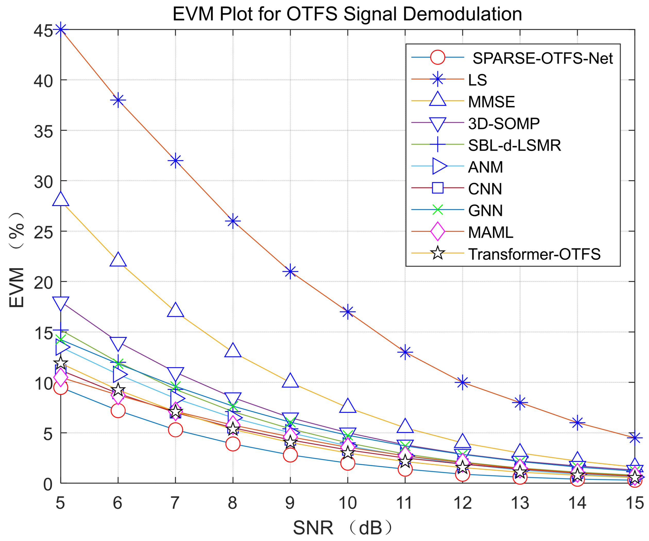
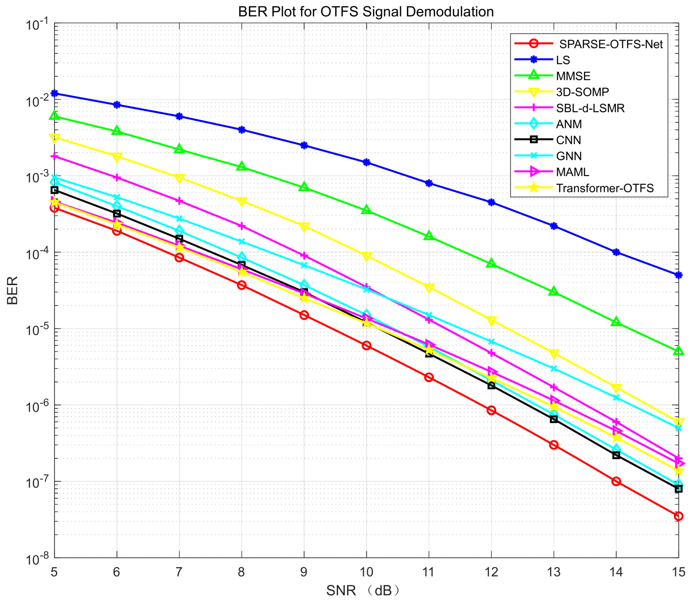
| Algorithm | SNR = 10 dB BER | SNR = 10 dB EVM (%) | Doppler Tracking Error (Hz) | Delay Resolution (μs) | Computational Complexity |
|---|---|---|---|---|---|
| LS | 1.5 × 10⁻³ | 17.0 | ±220 | 0.035 | O(P3 + P2MN) = 1.8 × 10¹⁰ |
| MMSE | 3.5 × 10⁻⁴ | 7.5 | ±180 | 0.025 | O(M3N3) = 4.4 × 10¹² |
| 3D-SOMP | 9.0 × 10⁻⁵ | 5.0 | ±110 | 0.012 | O(KPMN) = 3.0 × 10¹⁰ |
| SBL-d-LSMR | 3.5 × 10⁻⁵ | 4.0 | ±85 | 0.009 | O(KP3MN) = 8.8 × 10¹⁴ |
| ANM | 1.5 × 10⁻⁵ | 3.7 | ±40 | 0.001 | O((MN)3.5) = 5.6 × 10¹⁴ |
| CNN | 1.2 × 10⁻⁵ | 3.3 | ±70 | 0.018 | O(BMNd2) = 4.3 × 10⁹ |
| GNN | 3.2 × 10⁻⁵ | 4.8 | ±55 | 0.008 | O(kMNd2) = 3.4 × 10⁹ |
| MAML | 1.3 × 10⁻⁵ | 3.6 | ±40 | 0.006 | O(Lkd + Ld2) = 1.2 × 10⁸ |
| Transformer-OTFS | 1.2 × 10⁻⁵ | 3.0 | ±30 | 0.004 | O(kBMNd2) = 2.1 × 10¹³ |
| SPARSE-OTFS-Net | 6.0 × 10⁻⁶ | 2.0 | ±18 | 0.002 | O(kMNd2) = 2.0 × 10⁸ |
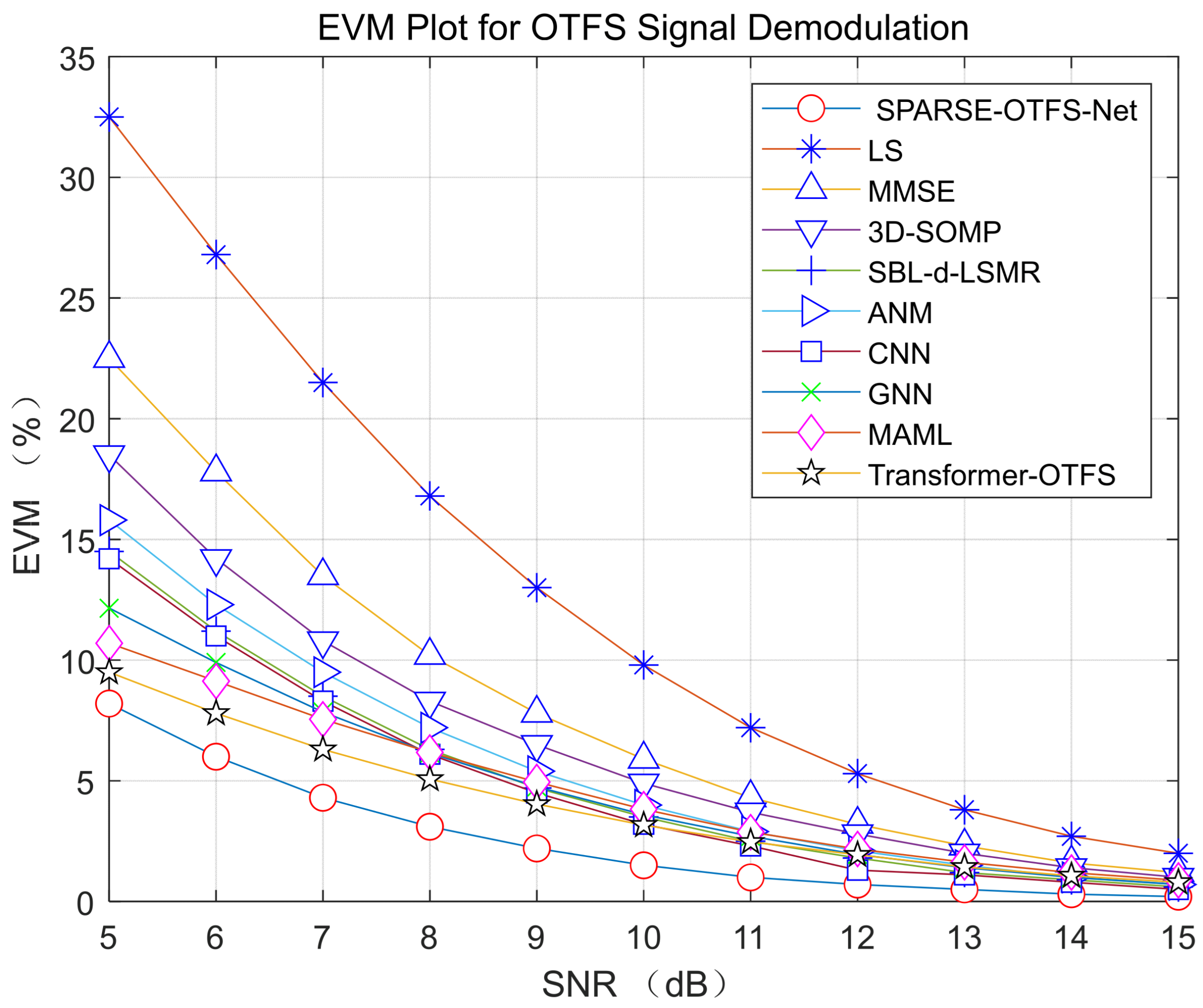
| Algorithm | SNR = 10 dB BER | SNR = 10 dB EVM (%) | Doppler Tracking Error (Hz) | Delay Resolution (μs) | Computational Complexity |
|---|---|---|---|---|---|
| LS | 2.0 × 10⁻⁴ | 9.8 | ±200 | 0.03 | O(P3 + P2MN) = 1.8 × 10¹⁰ |
| MMSE | 1.0 × 10⁻⁴ | 5.9 | ±150 | 0.02 | O(M3N3) = 4.4 × 10¹² |
| 3D-SOMP | 8.8 × 10⁻⁵ | 4.9 | ±100 | 0.01 | O(KPMN) = 3.0 × 10¹⁰ |
| SBL-d-LSMR | 1.5 × 10⁻⁵ | 3.5 | ±80 | 0.008 | O(KP3MN) = 8.8 × 10¹⁴ |
| ANM | 3.0 × 10⁻⁵ | 4.0 | ±30 | 0.001 | O((MN)3.5) = 5.6 × 10¹⁴ |
| CNN | 3.5 × 10⁻⁵ | 3.2 | ±60 | 0.015 | O(BMNd2) = 4.3 × 10⁹ |
| GNN | 1.1 × 10⁻⁵ | 3.6 | ±50 | 0.006 | O(kMNd2) = 3.4 × 10⁹ |
| MAML | 9.2 × 10⁻⁶ | 3.8 | ±35 | 0.005 | O(Lkd + Ld2) = 1.2 × 10⁸ |
| Transformer-OTFS | 8.0 × 10⁻⁶ | 3.2 | ±15 | 0.002 | O(kBMNd2) = 2.1 × 10¹³ |
| SPARSE-OTFS-Net | 5.0 × 10⁻⁶ | 1.5 | ±25 | 0.003 | O(kMNd2) = 2.0 × 10⁸ |
| Algorithm | SNR = 10 dB BER | SNR = 10 dB EVM (%) | Doppler Tracking Error (Hz) | Computational Complexity |
|---|---|---|---|---|
| LS | 2.0 × 10⁻³ | 17.5 | ±180 | O(P3 + P2MN) = 1.8 × 10¹⁰ |
| MMSE | 2.0 × 10⁻⁴ | 16.5 | ±150 | O(M3N3) = 4.4 × 10¹² |
| 3D-SOMP | 3.5 × 10⁻⁴ | 19.8 | ±85 | O(KPMN) = 3.0 × 10¹⁰ |
| SBL-d-LSMR | 4.0 × 10⁻⁵ | 12.7 | ±40 | O(KP3MN) = 8.8 × 10¹⁴ |
| ANM | 1.2 × 10⁻⁴ | 17.8 | ±30 | O((MN)3.5) = 5.6 × 10¹⁴ |
| CNN | 5.0 × 10⁻⁴ | 14.9 | ±70 | O(BMNd2) = 4.3 × 10⁹ |
| GNN | 1.1 × 10⁻⁴ | 10.7 | ±55 | O(kMNd2) = 3.4 × 10⁹ |
| MAML | 5.3 × 10⁻⁵ | 8.5 | ±35 | O(Lkd + Ld2) = 1.2 × 10⁸ |
| Transformer-OTFS | 6.0 × 10⁻⁵ | 7.3 | ±25 | O(kBMNd2) = 2.1 × 10¹³ |
| SPARSE-OTFS-Net | 1.4 × 10⁻⁵ | 6.5 | ±18 | O(kMNd2) = 2.0 × 10⁸ |
Disclaimer/Publisher’s Note: The statements, opinions and data contained in all publications are solely those of the individual author(s) and contributor(s) and not of MDPI and/or the editor(s). MDPI and/or the editor(s) disclaim responsibility for any injury to people or property resulting from any ideas, methods, instructions or products referred to in the content. |
© 2025 by the authors. Licensee MDPI, Basel, Switzerland. This article is an open access article distributed under the terms and conditions of the Creative Commons Attribution (CC BY) license (https://creativecommons.org/licenses/by/4.0/).
Share and Cite
Ling, Y.; Xu, J. SPARSE-OTFS-Net: A Sparse Robust OTFS Signal Detection Algorithm for 6G Ubiquitous Coverage. Electronics 2025, 14, 3532. https://doi.org/10.3390/electronics14173532
Ling Y, Xu J. SPARSE-OTFS-Net: A Sparse Robust OTFS Signal Detection Algorithm for 6G Ubiquitous Coverage. Electronics. 2025; 14(17):3532. https://doi.org/10.3390/electronics14173532
Chicago/Turabian StyleLing, Yunzhi, and Jun Xu. 2025. "SPARSE-OTFS-Net: A Sparse Robust OTFS Signal Detection Algorithm for 6G Ubiquitous Coverage" Electronics 14, no. 17: 3532. https://doi.org/10.3390/electronics14173532
APA StyleLing, Y., & Xu, J. (2025). SPARSE-OTFS-Net: A Sparse Robust OTFS Signal Detection Algorithm for 6G Ubiquitous Coverage. Electronics, 14(17), 3532. https://doi.org/10.3390/electronics14173532


