1. Introduction
The S-band, encompassing wavelengths from 1460 to 1530 nm, is increasingly vital for addressing the escalating demands of modern optical communication systems. With global data traffic projected to grow exponentially due to emerging technologies such as 5G networks, cloud-based data centers, and ultra-high-definition video streaming, the conventional C-band (1530–1565 nm) is nearing its capacity limit in wavelength-division multiplexing (WDM) systems [
1,
2,
3]. The S-band provides a critical extension of the spectral range, enabling high-density WDM systems to support additional channels and significantly enhance data transmission rates [
4,
5,
6]. This expansion is essential for applications requiring ultra-high bandwidth, such as inter-data-center connectivity, long-haul backbone networks, and emerging quantum communication systems. By unlocking the S-band’s potential, optical networks can achieve greater scalability and flexibility, ensuring robust performance for future communication infrastructure.
Distributed Raman Amplification [
7,
8,
9] offers a compelling solution for enabling efficient signal amplification in the S-band, overcoming limitations of traditional amplification methods. Unlike erbium-doped fiber amplifiers (EDFAs), which are optimized for the C- and L-bands but exhibit poor gain efficiency in the S-band due to their limited gain bandwidth, DRA leverages stimulated Raman scattering to provide broadband [
10], low-noise amplification directly within the transmission fiber [
11]. This distributed approach eliminates the need for discrete amplifier modules, reducing system complexity and mitigating signal degradation over long distances. Compared to semiconductor optical amplifiers (SOAs), which suffer from high noise figures and limited bandwidth [
12], DRA achieves superior noise performance and greater spectral flexibility, making it ideal for the S-band’s unique challenges. The ability to tune pump wavelengths allows DRA to tailor gain profiles, addressing nonlinear effects like four-wave mixing and pump efficiency constraints that are pronounced in the S-band. These advantages position DRA as a transformative technology for extending WDM systems into the S-band, supporting applications such as high-capacity metropolitan networks, submarine cables, and integrated C-/S-band systems for seamless spectral expansion [
13]. By optimizing DRA for the S-band, this study aims to unlock underutilized spectral resources, paving the way for next-generation optical networks with enhanced capacity and reliability.
This study, for the first time, employs a random Distributed Feedback (DFB) [
14,
15,
16] Raman amplifier with a half-open cavity [
17] design to optimize S-band amplification across a 5 THz spectrum (196.2–201.1 THz), addressing challenges such as nonlinear impairments and pump efficiency limitations. The choice of a random DFB Raman amplifier is motivated by its superior performance over conventional Raman amplification schemes, as demonstrated in prior work on long-haul transmission systems [
18,
19,
20,
21,
22,
23,
24]. Unlike traditional cavity-based Raman amplifiers that rely on two FBGs to form a Fabry-Perot cavity [
25,
26,
27], the random DFB configuration uses Rayleigh scattering as distributed feedback alongside a single FBG, enabling bidirectional second-order pumping without increasing relative intensity noise (RIN). This is critical for any WDM transmission systems, where forward pumping in conventional setups can transfer RIN to the signal, degrading performance [
28,
29,
30]. By optimizing the pump wavelength and incorporating an FBG to enhance gain uniformity, this configuration mitigates nonlinear effects like four-wave mixing and supports high-density WDM transmission, making it an ideal choice for extending S-band capacity in next-generation optical networks.
2. Methodology and Simulation
To investigate the performance of DRA in the S-band (1490.76–1527.99 nm, corresponding to 196.2–201.1 THz), this study employs a numerical simulation of a random DFB Raman laser amplifier with a half-open cavity configuration [
17]. The schematic design of the system is illustrated in
Figure 1.
The setup utilizes a 60 km SMF as the transmission medium, supporting 50 WDM channels with a 100 GHz channel spacing to evaluate high-density optical communication capacity. To achieve second-order distributed amplification, Raman fiber laser pumps in forward and backward directions, denoted as and , respectively, are downshifted by two Stokes shifts relative to the signal wavelengths and deployed at both ends of the fiber. Both pumps, simulated with a 200 GHz bandwidth, with a wavelength varied between 1318 and 1344 nm, are used to optimize amplification efficiency and gain uniformity. In each configuration, a single FBG with a 200 GHz bandwidth is upshifted by 88 nm relative to the Raman pump wavelength and placed at the end of the fiber span to reflect backscattered Rayleigh Stokes-shifted light. This setup forms a random DFB laser that acts as a first-order backward pump, amplifying signals across the desired S-band.
The use of a single FBG at the end of the transmission span, rather than a pair forming a closed Fabry–Perot cavity, distinguishes the random DFB Raman amplifier from conventional Raman amplification schemes. This half-open cavity design leverages distributed Rayleigh scattering as feedback, significantly reducing RIN transfer from the forward pump. In conventional setups, forward pumping often introduces high RIN due to inherently noisy high-power pumps, which can degrade data transmission performance, particularly in dense WDM systems. By eliminating the forward-side FBG, the proposed system mitigates this issue for the price of reduced power conversion efficiency compared to closed-cavity first- and second-order Raman amplifiers. The random DFB configuration ensures stable performance, as it is less sensitive to environmental temperature variations than traditional cavity-based lasers, making it well-suited for the S-band’s challenging spectral region.
The numerical simulation was conducted using a model (confirmed experimentally in [
17,
31]) to capture the dynamics of signal propagation, pump–signal interactions, and nonlinear effects such as four-wave mixing. The simulation model accounts for residual Raman gain from fully depolarized primary pump to the S-band signal, pump depletion effects from both the forward and backward pumps to lower-order pump and signal components, double Rayleigh scattering (DRS), and amplified spontaneous emission (ASE) noise for each of the WDM channels. It distinctly tracks the evolution of noise and signal components at the simulated channel frequencies to analyze the optical signal-to-noise ratio (OSNR) dynamics. This approach enables a detailed description of the signal and noise power evolution at each frequency across the simulated S-band (196.2–201.1 THz), providing insights into the interplay of gain, noise, and depletion effects in the random DFB Raman amplifier system that can be described as [
17]:
where
P denotes the power of a signal/pump, and
n is the average power of the noise in the forward (+) and backward (−) directions, respectively. Subscript
s denotes the spectral component that corresponds to the wavelength of a signal at frequency
ν. Subscripts
1 and
2 correspond to the primary and secondary (FBG) pumps at frequencies
and
, respectively.
α represents the attenuation of the fiber at its corresponding frequency,
is the effective Raman gain coefficient from frequency
µ to frequency
ν,
ε is the Rayleigh backscattering coefficient, ∆
ν is the effective bandwidth,
h is Plank’s constant,
KB is Boltzmann’s constant, and
T is the absolute temperature. The values of the Rayleigh backscattering coefficients at
,
and the frequencies of the WDM grid are assumed to be 1.0 × 10
−4, 6.5 × 10
−5, and 4.5 × 10
−5 km
−1, respectively.
The boundary value problem was solved with a 4th-order Ruge Kutta (KR4) shooting method with a step size of 1 m. Primary pump
wavelength was systematically varied between 1318 nm and 1344 nm to identify an optimal configuration for amplification efficiency. To evaluate the system’s performance, the forward pump power for the first-order Raman laser was varied from 0.7 W to 1.0 W in increments of 100 mW, allowing for the analysis of power-dependent gain characteristics. The backward pump power was dynamically adjusted to achieve a net gain of 0 dB for a single optimized channel, ensuring transparent transmission for the reference channel. The remaining 49 WDM channels were simulated using the fixed pump power settings determined for the optimized channel, enabling assessment of gain uniformity across the entire simulated spectrum. The transmitted power per channel was set to −10 dBm to replicate realistic WDM system conditions, consistent with high-density optical communication requirements. ASE noise and signal propagation were modeled in a 125 GHz bandwidth. The FBG’s reflectivity was set to 99%. Using the modified optical time domain reflectometer (OTDR) technique together with the tunable laser [
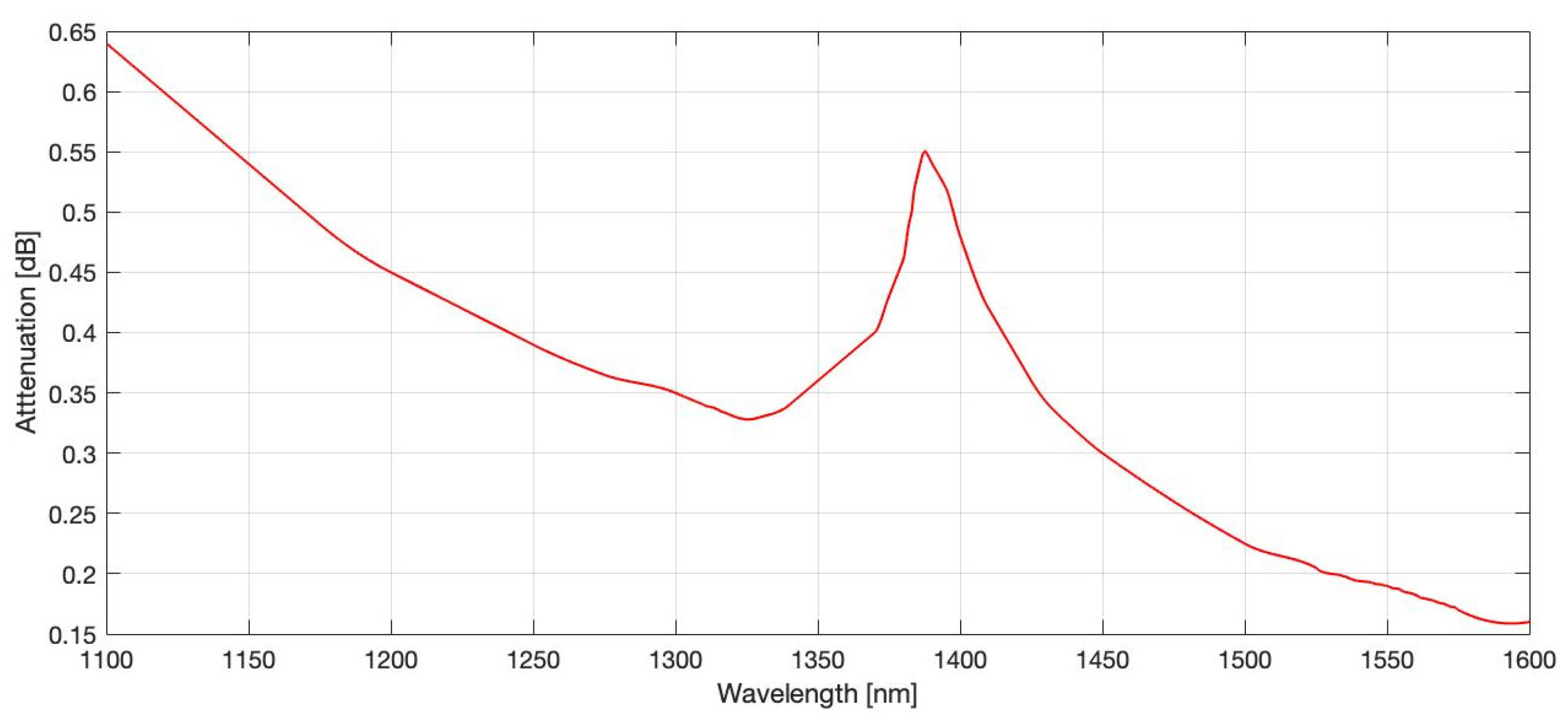
27], it was possible to experimentally measure the attenuation profile of standard SMF depicted in
Figure 2. These, in turn, were used as parameters in simulations for the Raman pump (
, FBG
) and each spectral component. Such an approach ensures realistic modeling of signal and pump losses across the whole spectrum.
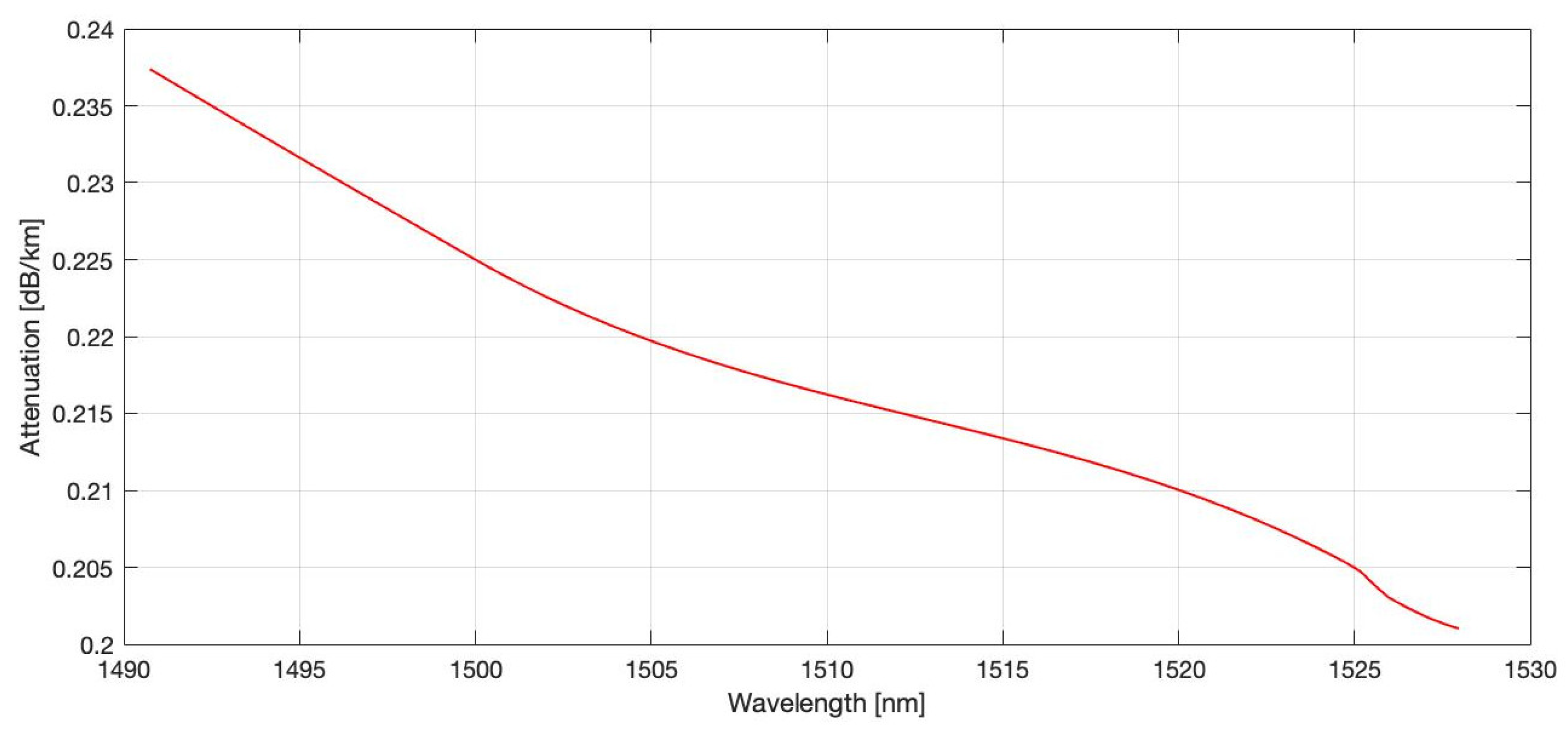
The attenuation profile of the WDM grid, illustrated in
Figure 3, offers essential insights into the spectral loss characteristics across the 50-channel array spanning the S-band. Detailed analysis of this profile indicates that the midpoint of the grid serves as an optimal reference for aligning simulation parameters to ensure accurate modeling of signal propagation and amplification dynamics. Accordingly, the central channel, designated as channel #25, was selected as the baseline for calibration due to its position at the median of the WDM spectral loss distribution. This choice leverages the assumed symmetry in attenuation effects across the 5 THz bandwidth, providing a balanced reference point for optimizing the random DFB Raman amplifier’s performance and minimizing variations in gain and signal power across the S-band spectrum.
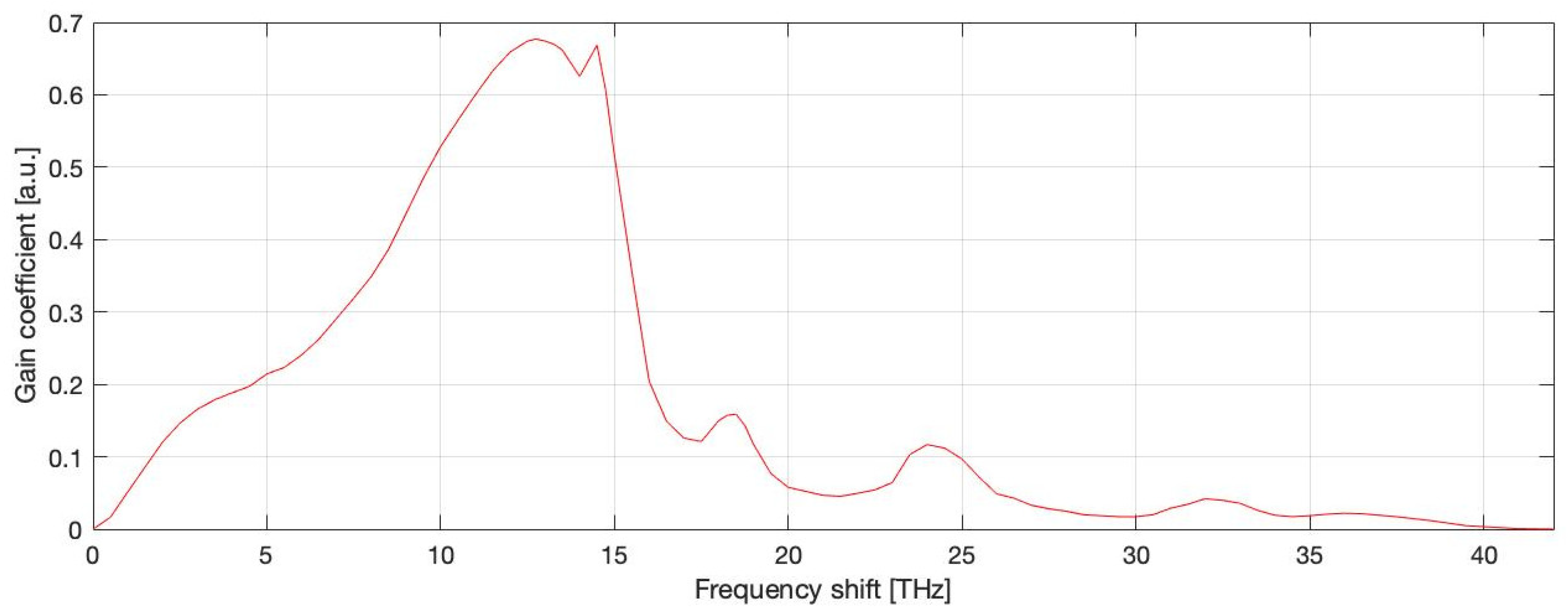
The Raman gain coefficient for the random DFB lasing and each of the 50 WDM channels was determined based on the Raman gain spectrum for fully depolarized pumps in standard SMF silica, as illustrated in
Figure 4. This selection ensures accurate modeling of gain dynamics across the simulated band, accounting for the spectral characteristics of the fiber and the depolarization effects of the pump lasers. The coefficients were tailored to reflect the experimentally validated gain profile, enabling precise simulation of signal amplification.
The Stokes-shifted Raman gain coefficient, which governs the efficiency of energy transfer from the FBG and the pump wavelength to each of the 50 WDM channels, presents a complex optimization challenge due to its wavelength-dependent behavior. As shown in
Figure 4, the Raman gain coefficient in the amplifier setup exhibits significant variations across the channel grid, driven by the spectral separation between the FBG and individual channel wavelengths. These variations result in differential amplification efficiencies, deviating from the assumed uniformity at the central channel (#25). Consequently, optimizing the system requires a sophisticated strategy that balances intrinsic fiber attenuation derived from the standard SMF profile in
Figure 2, with wavelength-specific Raman gain contributions. This dual consideration highlights the need for an advanced channel selection and calibration methodology to ensure consistent gain and minimal signal power variation across all WDM channels, enhancing the overall performance of the S-band DRA system.
3. Results
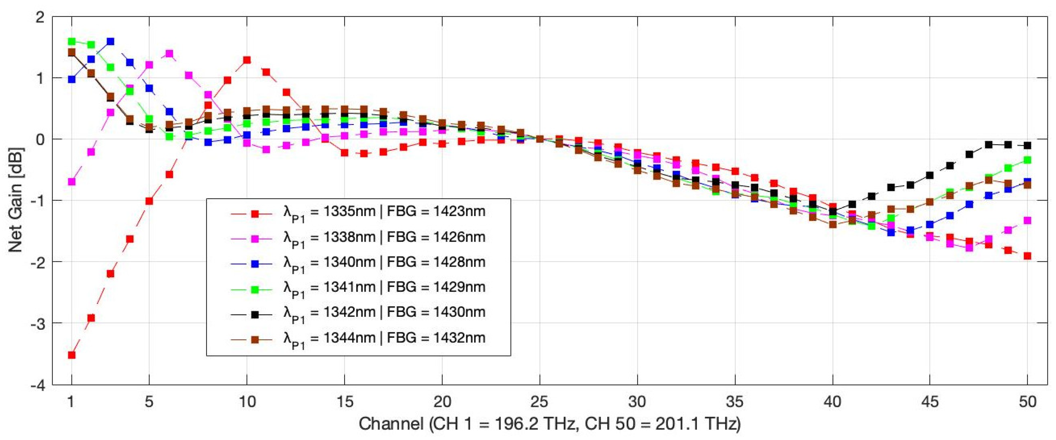
The net gain profile across the 50 WDM grid, spanning the S-band from 196.2 THz to 201.1 THz, was meticulously evaluated through numerical simulations, with the results presented in
Figure 5. The simulations explored eight distinct configurations, each featuring a primary pump wavelength paired with a corresponding Fiber Bragg Grating (FBG) wavelength upshifted by 88 nm: 1338 nm with FBG at 1426 nm, 1339 nm with FBG at 1427 nm, 1340 nm with FBG at 1428 nm, 1341 nm with FBG at 1429 nm, 1342 nm with FBG at 1430 nm, and 1344 nm with FBG at 1432 nm. The on–off net gain, measured in decibels (dB), was plotted for each channel to assess the amplification performance across the random DFB Raman amplifier system over a 60 km SMF.
The graphical representation reveals a diverse range of gain profiles, with net gain values fluctuating between approximately −3.5 dB and 1.5 dB across the channel array. The configuration utilizing a primary pump wavelength of 1342 nm and an FBG at 1430 nm stands out as the optimal setup, delivering the most consistent and highest on–off net gain profile across all 50 channels. This configuration exhibits a relatively flat gain curve, maintaining values close to or above 0 dB net gain for the majority of channels, with a peak gain approaching 1.5 dB at the beginning of the grid (channel #1) and minimal negative gain excursions (below −1 dB) at channel #40. In contrast, other configurations, with lower pump wavelengths, show more pronounced gain dips, particularly in the front of the WDM grid, indicating less uniformity. The superior performance of the P1 = 1342 nm and FBG = 1430 nm pair underscores the effectiveness of this wavelength combination in optimizing energy transfer, mitigating nonlinear effects, and achieving uniform amplification without a gain flattening filter, aligning with the study’s goal of enhancing S-band WDM system capacity.
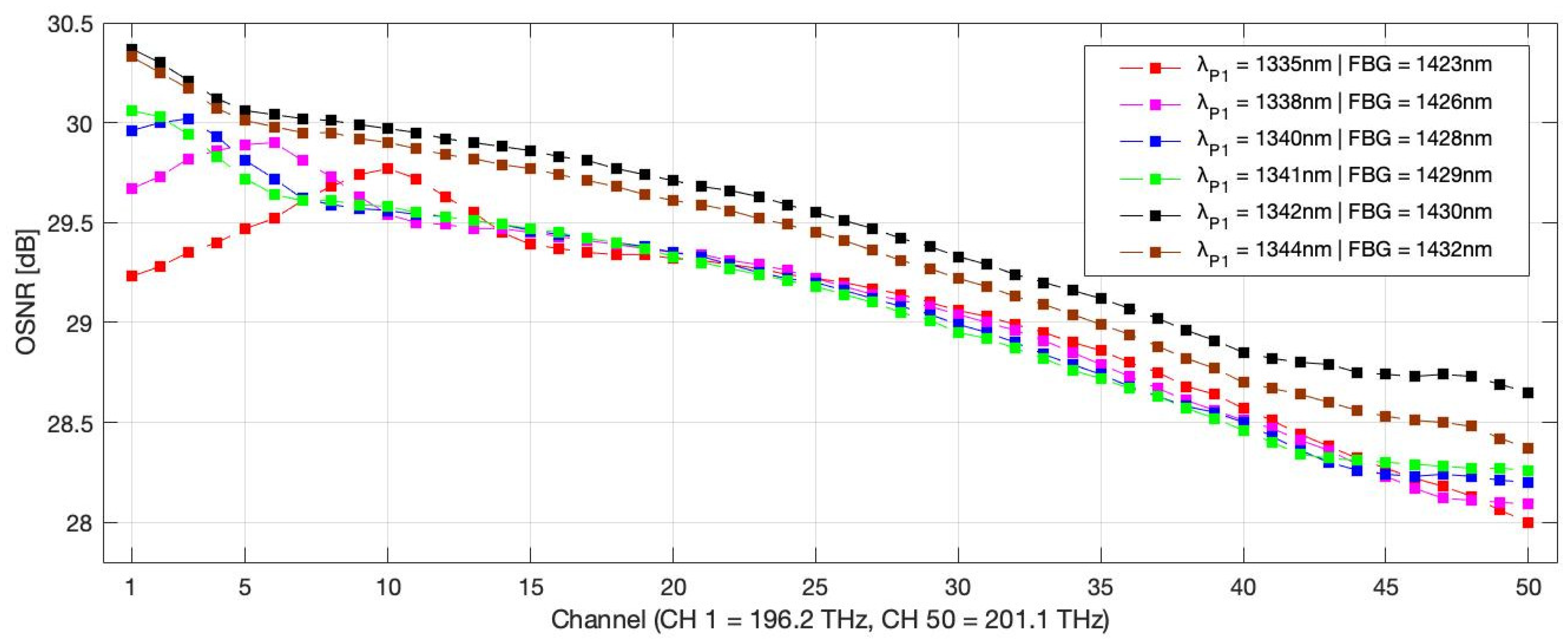
The OSNR was plotted in
Figure 6 for each channel to evaluate the signal quality and noise characteristics of the simulated system. The results highlight a range of OSNR values, spanning from approximately 28 dB to 30.5 dB across all configurations. The setup with a primary pump wavelength centered at P
1 = 1342 mn and FBG = 1430 nm emerges as the standout performer, delivering the highest and most consistent OSNR profile across all 50 channels. This setup maintains OSNR values above 29.5 dB for the first half of the grid, peaking near 30.5 dB at the beginning of the grid, with the lowest OSNR at the end of the spectrum. In comparison, other configurations exhibit lower OSNR values, indicating increased noise contributions. The superior OSNR performance of this optimal configuration underscores its effectiveness in minimizing ASE noise and double Rayleigh scattering (DRS) effects, while optimizing energy transfer within the S-band WDM system. This result reinforces the configuration’s suitability for achieving high-quality signal amplification, complementing its previously noted optimal net gain performance.
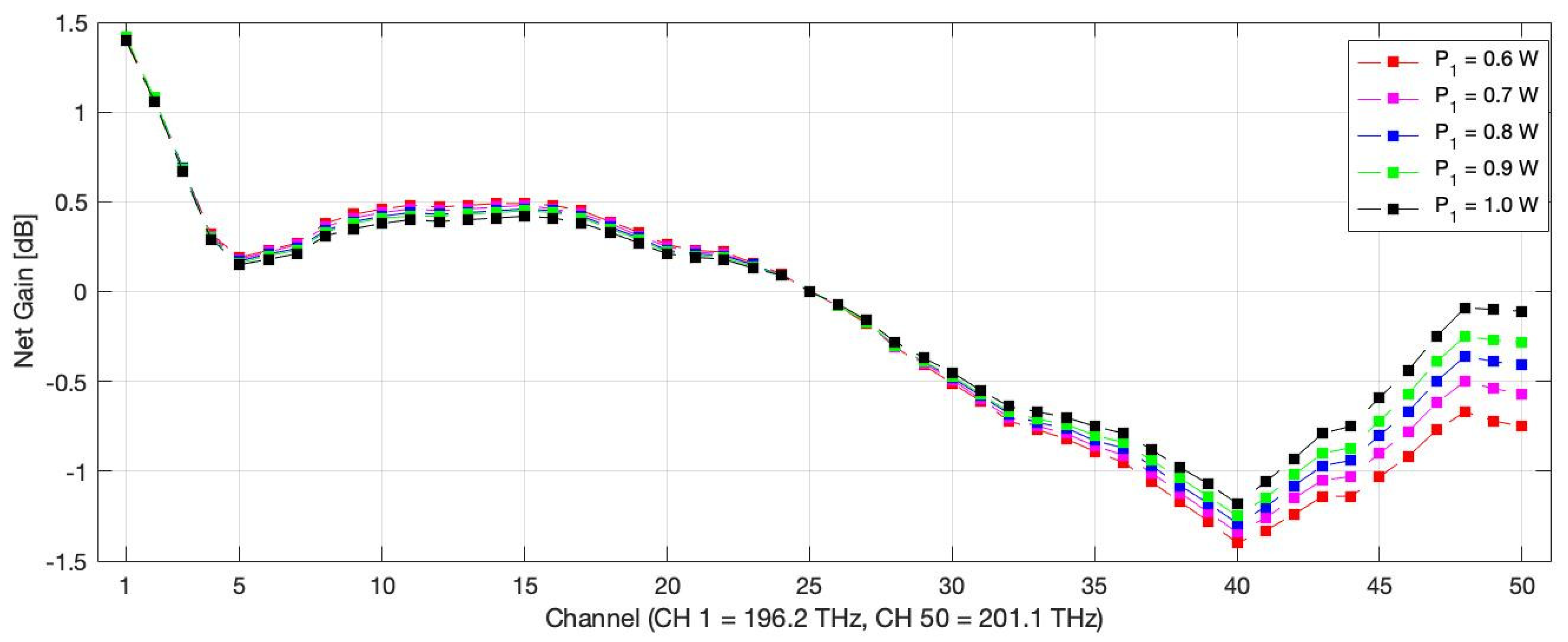
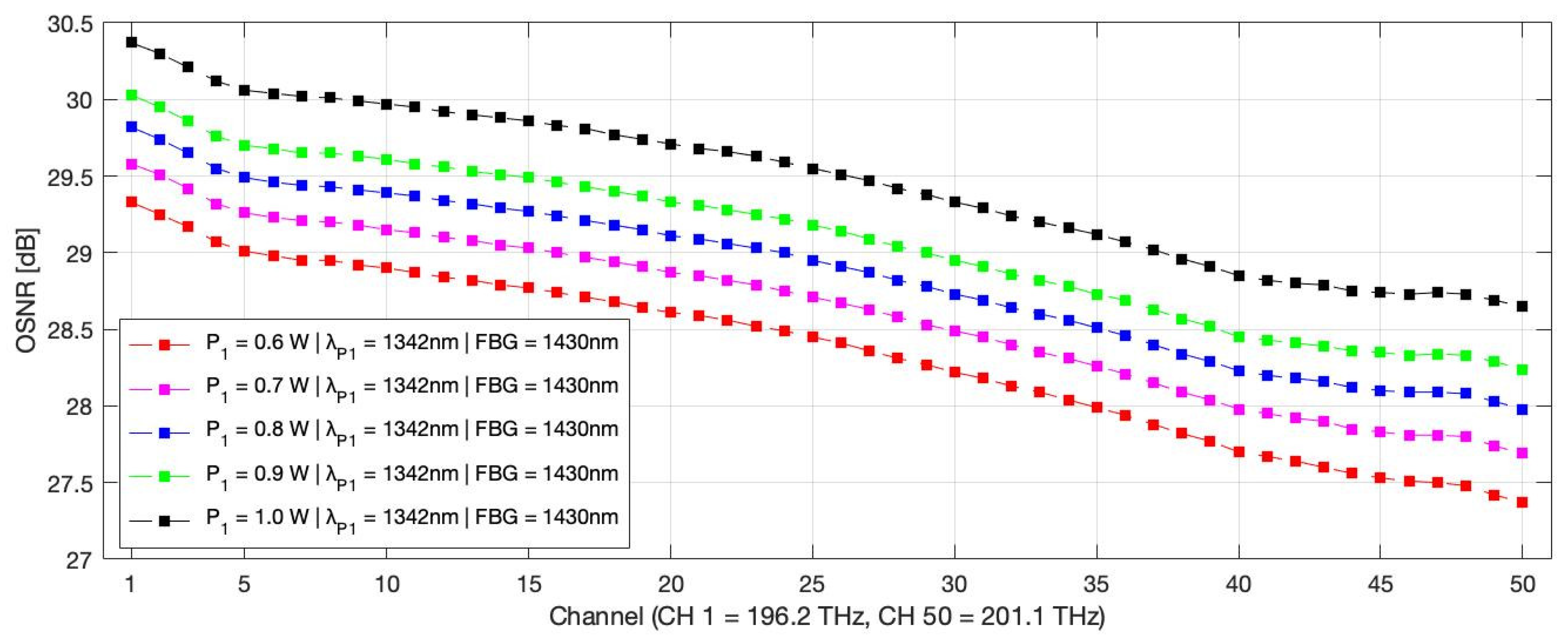
The optimal configuration, featuring a primary pump wavelength at 1342 nm paired with an FBG at 1430 nm, was selected based on its superior net gain and OSNR performance. A detailed analysis of the gain and OSNR dependence on primary pump power was conducted, with the pump power varying from 0.6 W to 1.0 W in 100 mW increments. The results, presented in
Figure 7 and
Figure 8, highlight the system’s performance.
The gain profile, depicted in
Figure 7, reveals a nuanced response to increased pump power. The first half of the WDM channel grid (channels 1–30) exhibits nearly identical gain values across all pump power levels, with a positive on–off net gain value above 0 dB for channels 1–25, with the sharpest increase for channels 1–4. In contrast, the second half (channels 26–50) demonstrates negative net gain. With rising pump power net gain values increases from approximately −1.3 dB at 0.6 W (CH#40) to a peak of −0.1 dB at 1.0 W (CH#50). This asymmetric enhancement suggests that higher pump power predominantly boosts amplification efficiency in the upper spectral range, likely due to improved energy transfer and reduced pump depletion effects with the help of an FBG mirror.
The OSNR performance, illustrated in
Figure 8, shows a consistent linear improvement with increasing pump power. Starting at approximately 28.5 dB at 0.6 W (CH#25), the OSNR rises steadily, reaching a maximum of 29.5 dB at 1.0 W (CH#25). This linear trend reflects a proportional reduction in amplified spontaneous emission (ASE) noise and DRS contributions as pump power increases, enhancing signal quality uniformly across the simulated spectrum. The best overall performance for both gain and OSNR is achieved at the 1.0 W pump power, highlighting its optimal setting for maximizing amplification efficiency and signal integrity in this configuration.
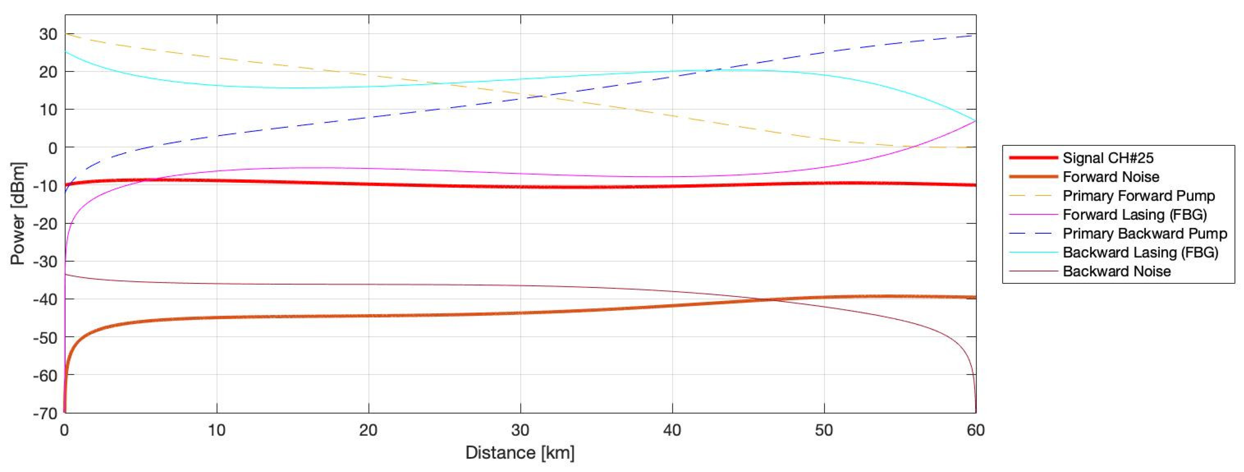
Figure 9 presents the comprehensive simulation results for the central channel #25 within the optimal random DFB Raman amplifier configuration. The plot highlights the evolution of key parameters, including the forward lasing (depicted in purple), which notably initiates from negative infinity due to the absence of a forward FBG. This unique buildup, driven by distributed Rayleigh scattering, minimizes RIN accumulation, enhancing signal stability and quality across the 60 km single-mode fiber. Additional traces, such as signal power and noise components, further illustrate the system’s robust performance, with a 0 dB net gain and an OSNR of 29.5 dB, showing the effectiveness of this half-open cavity design.
Figure 10 showcases the signal power profile for the optimized central channel #25 (depicted in red), alongside the two worst-performing channels, CH1 (shown in blue) and CH40 (shown in green), providing a detailed view of the signal evolution across the S-band using a random DFB Raman amplifier system. The optimized central channel #25 exhibits a stable and well-balanced signal power profile reflecting the optimal amplification achieved at the median of the WDM grid, benefiting from the best trade-off of the attenuation profile that translates to reasonable gain distribution facilitated by the half-open cavity design.
In contrast, CH#1, located at the lower spectral edge, displays over-amplification, with its signal power profile (in blue) exceeding the target gain by about 1.4 dB. This overcompensation is caused by the measured attenuation profile of the SMF.
Conversely, CH#40, positioned near the upper spectral edge, shows under-amplification, with its signal power profile (in green) falling short by approximately 1.2 dB below the target. This underperformance is attributed to increased attenuation effects at the longer wavelengths, limiting the energy transfer efficiency.
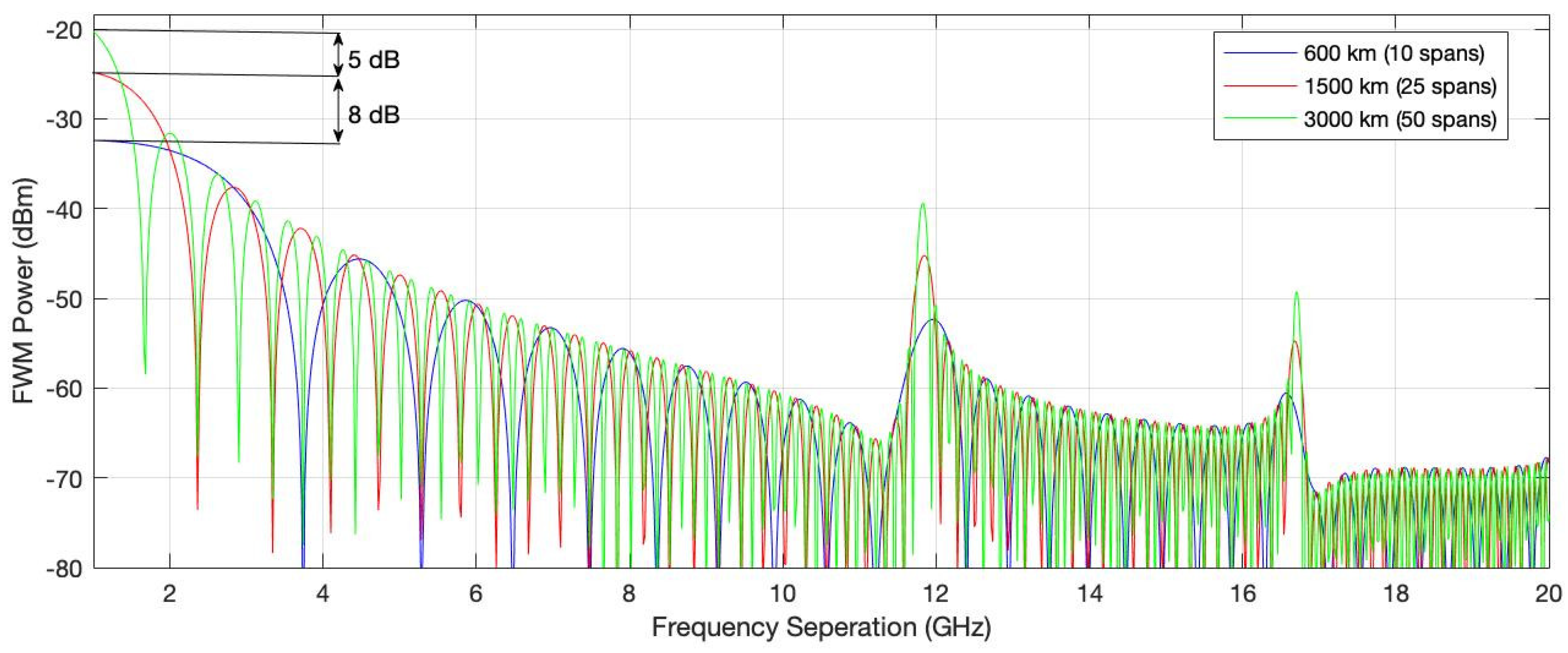
Figure 11 presents an analysis of the theoretical prediction of Four-Wave Mixing (FWM) power, utilizing the optimized signal power profile from the central channel #25 as the baseline within the S-band DRA system. FWM is a nonlinear optical effect that arises in WDM systems when multiple optical signals interact within a fiber, generating new frequency components through the mixing of three waves to produce a fourth. This phenomenon becomes significant in high-power, densely spaced WDM networks, as it can lead to crosstalk, signal distortion, and degradation of the OSNR, particularly over long transmission distances.
The simulation, conducted over the optimal random DFB Raman amplifier configuration (P1 = 1342 mn and FBG = 1430 nm, 1.0 W pump power) across a 60 km SMF span, extends the analysis to accumulated FWM power over multiple spans: 600 km (10 spans, depicted in blue), 1500 km (25 spans, depicted in red), and 3000 km (50 spans, depicted in green). The results indicate that the FWM power accumulation is predominantly noticeable in the lower frequency range up to 3 GHz, where the difference between configurations becomes apparent, while the higher frequency ranges exhibit nearly identical FWM levels across all distances. Quantitatively, the FWM power increases by approximately 8 dB from 600 km to 1500 km, reflecting a significant nonlinear buildup over the intermediate distance, and by an additional 5 dB from 1500 km to 3000 km, suggesting a diminishing incremental impact with extended span length. This behavior underscores the importance of managing nonlinear effects in long-haul communication systems, where FWM can limit transmission capacity and quality, particularly at the spectral edges. The findings provide valuable insights for designing high-capacity optical networks over extended multiple-span configurations.
4. Discussion and Conclusions
The results of this study demonstrate the efficacy of a random DFB Raman amplifier with a half-open cavity design in enhancing the S-band (196.2–201.1 THz) telecommunication window for high-density WDM systems. The optimal configuration, featuring a primary pump wavelength of 1342 nm and an FBG at 1430 nm with a 1.0 W pump power, achieved a low gain variation of just over 2 dB and a maximum OSNR of 30.5 dB, aligning with the hypothesis that a single FBG and optimized pump wavelength can mitigate nonlinear effects and improve amplification uniformity. These findings build on prior research, such as the study on random DFB laser-based Raman amplification with bidirectional second-order pumping [
21,
22,
23,
24], which reported extended transmission reaches (e.g., 7915 km in C-band) with reduced relative intensity noise [
28,
30]. While that work focused on C-band long-haul systems, our adaptation to the S-band reveals a comparable gain stability, albeit with a tailored approach to address the band’s unique attenuation and nonlinear challenges.
The observed asymmetric gain improvement in the second half of the WDM grid with increasing pump power suggests that higher pump energies enhance energy transfer at higher frequencies, a trend consistent with the Raman gain spectrum’s wavelength dependence. The linear OSNR increase further supports the hypothesis that minimizing ASE and DRS through optimized pump design reduces noise accumulation, outperforming conventional Raman setups with higher RIN. The FWM analysis, showing a cumulative power rise of 8 dB from 600 km to 1500 km and 5 dB from 1500 km to 3000 km, predominantly in the lower 3 GHz range, aligns with previous studies indicating that FWM intensifies with span count but plateaus beyond intermediate distances due to pump depletion. This suggests that the random DFB configuration effectively limits nonlinear crosstalk in long-haul S-band WDM systems, offering a viable alternative to traditional amplifiers like EDFAs, which are less effective in this spectral region.
The implications of these findings extend beyond S-band optimization to the broader field of optical communication, supporting applications such as submarine cables, inter-data-center links, and integrated C-/S-band networks. The half-open cavity design’s low RIN provides a robust framework for future high-capacity networks, potentially reducing the need for gain flattening filters and simplifying system deployment. However, the over-amplification of CH#1 and the under-amplification of CH#40 highlight the need for further refinement in edge-channel performance, possibly through adaptive pump control or hybrid fiber designs.
Future research directions could explore real-world validation of these simulation results over extended distances, integrating the random DFB amplifier with existing C-band infrastructure to assess spectral compatibility. Investigating advanced dispersion compensation techniques to mitigate edge-channel disparities and testing higher pump powers (e.g., beyond 1.0 W) to enhance gain uniformity could further elevate performance.

