Article

Anti-Windup Method Using Ancillary Flux-Weakening for Enhanced Induction Motor Performance Under Voltage Saturation

1
School of Electrical and Electronic Engineering, North China Electric Power University, Beijing 102206, China
2
The State Key Laboratory of Operation and Control of Renewable Energy & Storage Systems, China Electric Power Research Institute, Beijing 100192, China
*
Author to whom correspondence should be addressed.
Electronics 2025, 14(17), 3496; https://doi.org/10.3390/electronics14173496
Submission received: 28 July 2025 / Revised: 23 August 2025 / Accepted: 28 August 2025 / Published: 31 August 2025
(This article belongs to the Special Issue Power Electronics Controllers for Power System)

Abstract

When the speed of an induction motor (IM) exceeds its rated value, voltage saturation occurs, which degrades its performance. Traditional flux-weakening (FW) control suffers from delays due to cascaded PI regulators and sensitivity to rotor field orientation lag. Addressing these two issues, the proposed ancillary flux-weakening (AFW) method introduces two d-axis current compensation paths. One compensation path is from the reference value of the q-axis current, which simplifies the traditional three-PI cascade FW path into a single PI path in the transient process. The other compensation path is derived from the q-axis current tracking error to mitigate voltage saturation caused by orientation error. Comparative experiments show that during precise direction acceleration, the AFW method increases the current response time by 35% and reduces the peak voltage fluctuation by 38.98%. It also reduces low voltage ripple by 76.4% in inaccurate direction and burst load conditions. The results confirm a significant enhancement of dynamic performance and voltage anti-saturation capability in the FW region.

1. Introduction

High-speed induction motors (IMs) are extensively used in industrial applications such as CNC machines, electric vehicles, and distributed power generation [1,2,3]. As motor speed increases, the stator voltage amplitude also rises. When the speed exceeds the rated value, the output voltage of the inverter becomes insufficient to meet the stator voltage demand, leading to voltage saturation. Under voltage saturation, the current cannot follow the reference value, which reduces torque output capability in high-speed conditions. Flux-weakening (FW) control technology mitigates the impact of voltage saturation by reducing the excitation current, thereby lowering the stator voltage demand of the induction motor under high-speed conditions. Considering the robustness factors, researchers commonly adopt the FW control strategy based on the voltage closed-loop [4,5]. This strategy necessitates adding a voltage outer loop outside the current inner loop. However, the voltage–current dual closed-loop control structure exhibits significant control lag, which makes it difficult to achieve rapid voltage desaturation, resulting in poor dynamic performance of the motor in the FW region.
To address the dynamic problems caused by voltage saturation in the FW region, in [6,7], the parameters of the FW controller are designed to adaptively change with rotor speed to optimize the dynamic performance in high-speed conditions. However, the parameter design cannot directly adapt to the error of voltage amplitude, and there will still be large voltage fluctuations. Reference [8] developed a closed-loop voltage control method based on the d-axis reference current. It adjusted the outer PI controller by canceling the poles, which reduced the torque fluctuations. Furthermore, in [9], in order to reduce current oscillations, the actual excitation voltage is calculated based on the induction motor model, and an oscillation suppression technology is introduced.
Additionally, the authors of [10,11] enhanced current dynamic performance by modifying the system structure, specifically by replacing the current regulator with a model predictive control module to directly calculate the desired voltage vector. In addition to the general solutions for improving current dynamics at the overall drive system level, unique solutions specifically targeting current dynamics improvement in the FW region have also emerged. Especially in [12], the two-current controller structure is replaced with a single current controller, which eliminates voltage saturation. Nevertheless, the stable operating range of the method is limited, and a handoff is needed between the base-speed region and the FW region. Reference [13] proposes an optimized structure for multi-state voltage control. Compared with the traditional voltage loop, the dynamic performance of the electric current was improved. Similarly, researchers have implemented the phase control strategy using a single current controller, replacing the conventional dual PI controllers on the dq axis current, thereby enhancing the current tracking performance in the FW region [14].
In addition to the current loop optimization method, optimization of the voltage controller is also a common method for improving the dynamic performance of IM in the FW region. In [15], the voltage-current cascade control structure was normalized as a unified system. Furthermore, researchers have analyzed the voltage margin requirements during current dynamic changes in the FW region. Based on this analysis, they proposed a solution to enhance current dynamic control by reserving voltage [7]. However, this approach can negatively impact the maximum torque output in the FW region. Reference [16] explored the non-smooth transition from the base speed region to the FW region, revealing the discontinuity at the rate of change of the voltage amplitude. An arc-shaped transition trajectory was designed to achieve a smooth transition to the FW region. In [17], the trajectories of the voltage and current vectors are optimized, but the method is designed for specific working conditions: transition from maximum torque to non-maximum torque.
Additionally, FW control heavily depends on precise orientation, but factors like parameter variations and control delays can cause orientation lag [18]. Existing approaches usually address orientation lag by identifying parameters such as the rotor time constant [19]. However, the orientation lag cannot be entirely eliminated, particularly during dynamic processes. Reducing the sensitivity to orientation lag from the perspective of FW control itself still requires further exploration.
It can be seen that traditional FW control methods primarily suffer from the following problems. Due to the use of a dual closed-loop structure for voltage and current controllers during the optimization process, the voltage and current control remain unchanged. Consequently, three PI controllers are typically required from the onset of voltage saturation to the completion of FW control during the FW process. Furthermore, FW control depends heavily on precise orientation. Existing methods usually address the problem after orientation through parameter identification. However, orientation lag cannot be completely eliminated in dynamic processes. The comparison between the conventional FW schemes and the proposed FW scheme is summarized in Table 1, and the main contributions of this article are summarized as follows.
(1)
To address the FW delay caused by the three-stage PI cascade, a compensation path is designed, simplifying the FW structure to one PI controller during dynamic processes.
(2)
To mitigate FW failure due to orientation lag, the q-axis current error is utilized to measure and eliminate the magnetization component induced by the increase of q-axis current during dynamic processes.
The contents of this paper are as follows: Section 2 provides the basic theory of FW control. Section 3 analyzes the problem of FW delay in the traditional cascade structure and the influence of orientation error on FW control. Section 4 proposes the ancillary FW scheme. Finally, the proposed method is verified using comparison experiments in Section 5.
Table 1. Comparison of different FW methods.
MethodsStructure Optimization of FW LoopNumber of PI Controller in FW LoopSensitivity to Parameter ChangesVoltage Fluctuations During Changes of i s q and ω e Remarks
1Adaptive parameters of FW controller [6]No3HighMediumFailure to consider voltage fluctuations from i s q changes
2Unified design of controller
Parameters [7]
Yes3HighMedium
3Limitation of u s d [8]No3LowHighUtilizes the voltage overshoot rather than suppressing it
4Smooth transition to FW condition [16]No3LowMediumDesigned for specific condition
5Rapid convergence to steady state point [17]No3HighHigh
6Single current control [7,14,15]Yes2HighLowHandoff is needed
7Proposed methodYes1MediumLow/

2. Basic Theory of Flux-Weakening Control

In the rotor flux-oriented control (RFOC)-based IM driving system, the stator voltage equation in the synchronous rotating frame can be expressed as:
u s d = R s i s d + σ L s s i s d ω e σ L s i s q + L m L r s λ r u s q = R s i s q + σ L s s i s q ω e σ L s i s d + L m L r ω e λ r
where u s d and u s q are the d- and q-axis voltages, respectively; i s d and i s q are the d- and q-axis currents, respectively; ω e is the synchronous angular frequency; R s is the stator resistance; L s and L r are the stator self-inductance and the rotor self-inductance, respectively; L m is the mutual induction between the stator and the rotor; λ r is the rotor flux in synchronous reference; s is the differential operator; and σ is the total leakage factor ( σ   =   1     L m 2 / L s L r ).
By neglecting the stator resistance and the dynamic terms of (1), the steady-state IM voltage equations of FW region can be simplified to:
u s d = ω e σ L s i s q u s q = ω e L s i s d .
According to (2), the voltage amplitude increases with the operating frequency. To avoid the voltage exceeding the output boundary of the inverter, the voltage closed loop is introduced to the vector control system of IM. As shown in Figure 1, the output voltage amplitude of the current controller is fed back to the voltage controller. On this basis, the output voltage amplitude can be constant at the maximum value. In space vector pulse width modulation (SVPWM), the output boundary of the inverter is a regular hexagon with a side length of 2 U d c / 3   ( U d c is the DC-Link voltage). To minimize harmonics in the output voltage, the inscribed circle of the hexagon is typically regarded as the maximum voltage the inverter can produce. Thus, the maximum voltage in this paper is U d c / 3 0.5 .
The system voltage and current limiting conditions in the FW region can be expressed as:
i s d 2 + i s q 2 = i s max 2 u s d 2 + u s q 2 = u s max 2 ,
where u s max and i s max are the maximum voltage and maximum current of the system, respectively.
By substituting (2) into (3), the system constraints can be expressed by the stator current:
ω e σ L s i s q 2 + ω e L s i s d 2 = u s max 2 .
Under the adjustment of the voltage closed loop, the stator current satisfies (4). Thus, (4) can be regarded as the trajectory of the current vector in the FW region. According to the voltage closed-loop-based FW scheme in Figure 1, three cascaded PI controllers are required for FW control, which leads to the degradation of the dynamic performance. The next section analyzes the degradation of the dynamic performance.

3. Analysis of Voltage Saturation Problem in Flux-Weakening Region

In this section, both dynamic issues caused by the cascade structure and the orientation lag are thoroughly discussed, and their specific impacts are analyzed.

3.1. Voltage Saturation Caused by Cascaded PI Structure

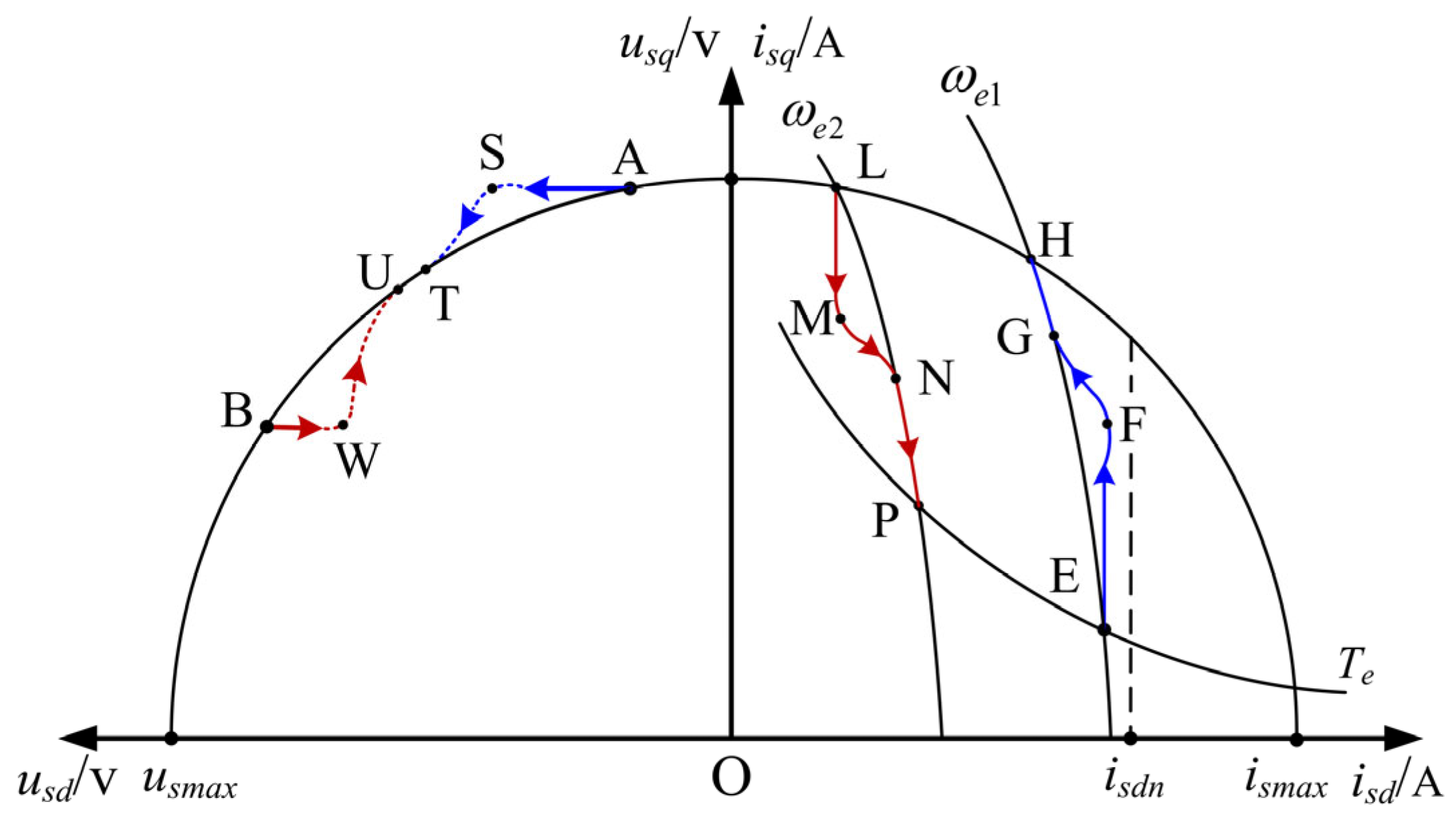
First, the trajectories of voltage and current vectors are given in Figure 2 in synchronous rotating reference frames of i s d i s q and u s d u s q . In Figure 2, EH and LP are the current trajectories corresponding to (4) under different synchronous frequencies ( ω e 1 and ω e 2 , ω e 1   <   ω e 2 ). HL is the current limitation boundary. AB is the voltage boundary. T e is the constant torque curve. In non-maximum torque conditions, the stator current vector is located at the intersection of the voltage constraint ellipse and the constant torque curve, which corresponds to point E in Figure 2. Under maximum torque conditions, the stator current vector is located at the intersection of the voltage constraint ellipse and the current limit circle, which corresponds to point H in Figure 2. When the demand torque changes, the current vector moves between points H and E.
The dynamic process can be divided into torque change and speed change. The acceleration process involves changes in both torque and speed and is therefore used as an example to discuss the current trajectory. Based on the previous discussion, the ideal current vector trajectory during the complete acceleration process (with no load torque change in steady state) is E H L P , which corresponds to three segments: torque increase (EH), maximum torque output (HL), and torque decrease (LP). It can be observed that the i s d and i s q of the three trajectories (EH, HL, LP) change synchronously; thus, it is necessary to perform coupling control on i s d and i s q . However, during the transition between maximum and non-maximum torque (i.e., the EH and LP segments in Figure 2), i s q and i s d are independently controlled by the speed and voltage regulators, respectively, as shown in the control block diagram of Figure 2. The coupling control between i s d and i s q cannot be achieved, preventing the current vector from following the ideal trajectory. The specific manifestations are as follows:
When the system enters a dynamic state due to changes in load torque or speed reference, i s q r e f adjusts before i s d r e f . This change in i s q r e f causes an increase (during acceleration or load increase) or a decrease (during deceleration or load decrease) in voltage amplitude. Subsequently, to suppress voltage fluctuations, i s d must be adjusted. However, since i s d r e f cannot be directly modified based on changes in i s q r e f , the control of i s d relies on feedback from the voltage regulator. The voltage regulator has a major limitation: it cannot predict voltage overshoot (saturation) or voltage drop (under-utilization) and can only adjust after fluctuations occur, leading to a delay in i s d control. At the same time, as shown in Figure 2, three PI regulators are used to achieve coupling control between i s d and i s q . The operation passes through the q-axis current regulator (causing a voltage change), the voltage regulator (adjusting i s d r e f ), and the d-axis current regulator (modifying i s d ) to complete the FW control. Due to the triple connection of these controllers, the current coupling control cannot be realized instantly, leading to reduced dynamic performance. Both the lengthy control chain and the hysteresis of the flux-weakening control contribute to the issue of anti-saturation delay.
The voltage saturation problem is reflected in the current trajectory: Figure 2 shows the trajectory of the current and voltage vectors during the acceleration process from ω e 1 to ω e 2 . In Figure 1, the curve HL is the current limiting boundary. Point E is the initial point. To output maximum torque and increase speed, the current vector is expected to move from point E to point H. The increase in i s q leads to the voltage saturation. Due to the loss of current control ability caused by voltage saturation, i s d cannot immediately decrease with the increase in i s q , resulting in the actual trajectory (EFGH) deviating from the ideal trajectory (EH). The corresponding voltage trajectory (AST) exceeds the voltage limit boundary (AB). Since the maximum torque is not required when the speed reaches the reference value ω e 2 , i s q decreases. Similarly, i s d cannot increase immediately with the decrease of i s q . The actual current trajectory (LMNP) deviates from the ideal trajectory (LP). Correspondingly, the voltage trajectory (BWU) decreases from the voltage limit boundary (BA).
In summary, the voltage saturation issue is caused by two factors: (1) The d-axis current cannot adapt to changes in the q-axis current due to the absence of direct control from i s q to i s d ; (2) The three-stage cascade structure introduces control delays, preventing a rapid current response.

3.2. Voltage Saturation Caused by Orientation Lag

Control delays and parameter variations in induction motor control systems impact the accuracy of rotor field orientation, leading to incomplete decoupling of torque and excitation currents. Flux-weakening control is particularly sensitive to orientation accuracy, especially during transient processes.
When the rotational speed increases, the current is precisely adjusted to increase in a vertically upward direction, as indicated by Δ i s 1 in Figure 3. Meanwhile, the voltage increase is corrected to align horizontally, as demonstrated by Δ u 1 . When orientation lag occurs (angle error is represented as Δ θ ), the torque current grows along the incorrect q-axis, as indicated by Δ i s 2 in Figure 3. Similarly, the voltage increase direction is represented by Δ u 2 . It is clear that the angles of Δ u 2 and Δ u 1 are not the same. When their magnitudes are identical, Δ u 2 causes greater voltage saturation. This implies that orientation lag can aggravate the voltage saturation problem in the FW region. The following derivation provides a quantitative analysis of the impact of orientation lag on voltage saturation:
In the incorrect coordinate system, the actual changes in the d-axis and q-axis currents corresponding to the current variation Δ i s 2 are as follows:
Δ i s q r e a l = | Δ i s 2 | cos Δ θ Δ i s d r e a l = | Δ i s 2 | sin Δ θ ,
where Δ θ is the orientation error angle and Δ θ   =   0 is the precise orientation.
By substituting (5) into (4), the voltage saturation caused by orientation lag can be obtained:
u s 2 = [ ω e L s i s d 0 + | Δ i s 2 | sin Δ θ ] 2 + [ ω e σ L s i s q 0 + | Δ i s 2 | cos Δ θ ] 2 U s a t = u s U s max ,
where i s d , q 0 is the initial value during the dynamic process.
i s d , q 0 can be obtained by the torque equation:
T e 0 = 3 n p L m 2 i s q 0 i s d 0 2 L r ,
where n p represents the pole pair.
According to (6), Figure 4 shows the relation among the magnitude of the current change ( Δ i s 2 ), the angular error ( Δ θ ), and the size of the voltage saturation value ( U s a t ). The following conclusions can be drawn from Figure 4:
(1)
Under the same Δ i s 2 , the voltage saturation increases noticeably as Δ θ grows.
(2)
An increase in Δ i s 2 similarly results in voltage saturation, but when Δ θ equals zero, the saturation caused by Δ i s 2 is minimal. However, when θ increases, the rate of increase in voltage saturation due to changes in Δ i s 2 rises significantly.
(3)
As analyzed in Section A, the failure to quickly synchronize the dq-axis current control is the direct cause of voltage saturation. Conclusion (2) suggests that orientation lag amplifies the voltage saturation issue induced by the current control.
Figure 4. Relationship between current increment and voltage error with directional error angle.
Electronics 14 03496 g004

4. Proposal of the Ancillary Flux-Weakening Method for Voltage Anti-Saturation

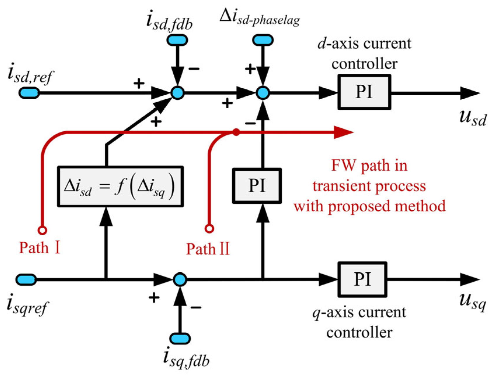
To overcome the issue of voltage saturation resulting from FW cascade structures and orientation lag, this paper proposes an auxiliary flux-weakening (AFW) control strategy, which comprises two compensation paths as shown in Figure 5.
Figure 5 shows the proposed auxiliary weak magnetic (AFW) controller structure, which introduces two compensation paths to improve the anti-saturation performance under voltage saturation. Path I passes coupling compensation and directly feeds the change of i s q r e f ( Δ i s d ) into the FW control loop to generate a d-axis compensation current, thereby effectively shortening the length of the anti-saturation control path. Path II uses the q-axis current tracking error ( i s q r e f i s q , f d b ) as the input of the PI controller to generate compensation; at the same time, due to the increase of i s q ( Δ i s q ) and a certain phase delay ( Δ θ ), the increment ( Δ i s d - p h a s e l a g ) of the flux current component is used as the input of the additional compensation path. Total compensation is added to the output of the voltage regulator, solving the problem of anti-saturation delay caused by the excessively long control chain and weak magnetic hysteresis, and also alleviating the voltage saturation caused by the magnetic flux orientation error.

4.1. Auxiliary Flux-Weakening for Reducing Voltage Saturation Caused by the Cascade Structure Delay

Based on the analysis in Section 3, the traditional voltage–current cascade FW strategy exhibits significant control delays during transitions between maximum and non-maximum torque. To address this, this paper proposes a compensation scheme to reduce such delays. As shown in path I in the AFW module in Figure 5, this paper introduces a compensation loop that differs from the traditional three-stage cascade structure to achieve synchronous control of dq-axis currents. This compensation strategy, grounded in the maximum voltage limit circle equation and steady-state voltage equation, determines the optimal change in the d-axis current corresponding to changes in the q-axis current during dynamic processes. Section 3 concludes that voltage saturation in the FW region is driven by the increase in i s q r e f . Through coupling compensation, changes in i s q r e f are directly fed back into the flux-weakening control loop, significantly shortening the anti-saturation control path. The compensation model of the d-axis current is derived as follows:
According to (4), i s d can be expressed as a function of i s q and ω e :
i s d = f ω e , i s q = u s max 2 ω e σ L s i s q 2 ω e L s .
From (8), when i s q and ω e change, i s d should adjust accordingly, achieving synchronous current control. Since the steady-state value of i s d is determined by the voltage closed-loop, the compensation only needs to consider the relative change in i s d compared to its steady-state value. In traditional methods, voltage saturation issues arise because the relative change in i s d r e f during transient processes cannot be provided in time. The relative change in isd can be expressed as:
Δ i s d = i s d 1 i s d 0 = f ω e 0 + Δ ω e , i s q 0 + Δ i s q f ω e 0 , i s q 0 ,
where i s d 0 , i s q 0 and ω e 0 are the initial values of dq-axis current and speed, respectively, and Δ ω e and Δ i s q are the change values of ω e and i s q in the dynamic process, respectively.
According to (9), the compensation amount for i s d is derived from changes in speed or torque. When this compensation is applied to the d-axis current, the reference current value must satisfy the maximum current limit:
i s d 0 + Δ i s d 2 + i s q 0 2 i s max 2
Substituting (8) into (10) yields the limit value for the compensation component of i s d , as expressed in (11).
Δ i s d max 1 ω e L s u s max 2 ω e σ L s i s max 2 2 1 σ 2 i s d 0 .
The compensation path plays an auxiliary role in the FW control. Voltage saturation in the FW region primarily results from an increase in the q-axis current reference. The auxiliary FW strategy enables real-time adjustment of the flux current in response to changes in the q-axis current. By completing the FW operation before significant voltage saturation occurs due to q-axis current error, this approach effectively minimizes the risk of voltage saturation. Additionally, voltage saturation prevention is no longer dependent on the traditional three PI regulators, significantly reducing the dynamic delay in FW control while also speeding up the response time for preventing voltage saturation.

4.2. Auxiliary Flux-Weakening for Reducing Voltage Saturation Causde by Orientation Lag

Changes in motor parameters and digital control delays often result in steady-state lag in field-oriented control. Furthermore, during sudden acceleration, the instantaneous slip frequency is typically lower than the actual value, leading to a transient lag in field orientation. As analyzed in Section 3, tracking errors in the q-axis current during transient conditions can cause voltage saturation, while the lag in field orientation amplifies this effect. To address this, the paper introduces a second FW compensation path that incorporates a proportional–integral (PI) controller following the i s q tracking error. The structure of this compensation loop is depicted in path II of the AFW module shown in Figure 5.
According to (6), the increase of flux current component ( Δ i s d ) corresponding to the increase of q-axis current under magnetic field orientation hysteresis can be expressed as:
Δ i s d p h a s e l a g = Δ i s q tan Δ θ .
According to (12), phase lag results in an increase in flux current during transient processes, which is proportional to the q-axis current error. Thus, there are two conditions for the appearance of Δ i s d - p h a s e l a g : an increase in i s q and a certain phase delay. So, i s d has a significant impact during sudden acceleration and sudden loading, exacerbating the problem of voltage saturation. Focusing on this problem, Δ i s q is employed as the input for an additional compensation path. This compensation feeds the tracking error of i s q back to the FW control loop via a PI regulator, as shown in Figure 5, to compensate for the d-axis current error ( Δ i s d - p h a s e l a g ) caused by magnetic field orientation lag.
It is proposed that the AFW method does not require parameter adjustment for different scenarios. As shown in Figure 3, when a directional lag of angle Δ θ occurs, the torque current increases along the lagging direction ( Δ i s 2 ), and the voltage increment is also shifted by an angle. According to (12), the resulting increase in the flux current component on the q-axis ( Δ i s d - p h a s e l a g ) is determined by both Δ θ and the magnitude of Δ i s 2 . This increment in the flux current component ( Δ i s d - p h a s e l a g ) is then used as the input to an additional compensation path. Therefore, for a fixed increase in torque current ( Δ i s 2 ), the compensation amount ( Δ i s d - p h a s e l a g ) increases as the directional lag angle Δ θ grows. In other words, Δ i s d - p h a s e l a g adaptively increases with the severity of the directional lag. Hence, the proposed AFW method is effective against all causes of directional lag and does not require adjustment across different operating conditions.
In conclusion, the two compensation strategies effectively solve the following key issues: (1) It solves the problem that the traditional q-axis current command struggles to directly adjust the d-axis current command, and reduces the dependence of the flux current command on the voltage controller; (2) It effectively reduces the voltage saturation problem caused by the increase of the q-axis current under the magnetic field orientation lag, and suppresses the magnetization component caused by the orientation lag.

4.3. Method Stability Analysis

The proposed method consists of two compensation loops, and its stability is proven as follows: the block diagram showing the induction motor flux-weakening system is depicted in Figure 6a. For ease of analysis, the closed-loop structure of Figure 6a has been simplified. By ignoring the constant signals i s d f d b and u s m a x , the simplified structure is depicted in Figure 6b.
According to the structural block diagram in Figure 6b, the closed-loop transfer functions of the proposed method can be written as:
G n e w = P I 2 × P I 1 × 1 + 10 σ P I 1 × P I 2 j P I 1 + P I 3 P I 2 L s σ ω e ρ 1 P I 2 × P I 1 × P I 1 + P I 3 P I 2 L s σ ω e ρ 1 ρ 2 + 1 ρ 2 .
The ρ 1 , ρ 2 and P I n ( n = 1 , 2 , 3 ) in (13) can be expressed as:
ρ 1 = 1 + P I 2 × P I 4 ρ 2 j ρ 2 = P I 4 L s ω e 1 P I n = K p n + K i n s   n = 1 , 2 , 3 .
According to the closed-loop transfer function in (13), the bode diagram can be drawn under different PI parameters of the weak magnetic auxiliary, as shown in Figure 7. According to the amplitude and phase frequency characteristics of the Bird diagram, it can be seen that the system is still stable after adding the proposed AFW method. At the same time, the selection of K p and K i has a certain impact on the system response:
(1)
K p becomes larger: The system quickly approaches the steady-state value (response speed increases), but the stability time may be longer due to overshoot or oscillation.
(2)
K i becomes larger: the steady-state error is significantly reduced or even eliminated, but the excessively strong integral effect may cause the overshoot to increase and the adjustment time to be extended due to integral saturation.
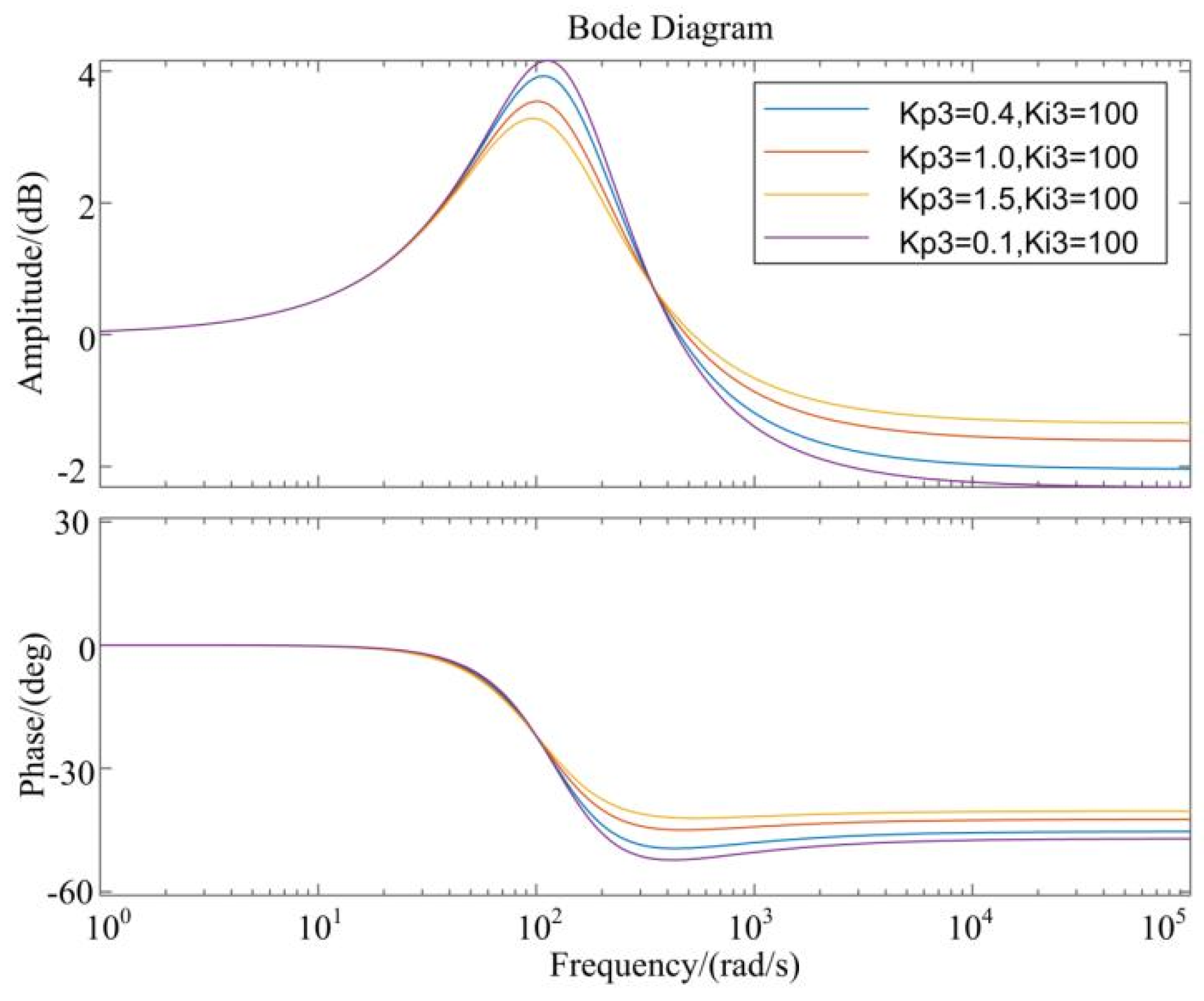
Figure 7. Bode diagram of closed-loop transfer function of the proposed method.
Electronics 14 03496 g007
When making PI adjustments, the adjustment of its parameters must follow the principle of “proportion first and points later”. Through experiments and simulation, dynamic and steady-state performance were comprehensively considered, and the final K p 3 is 0.4 and the K i 3 is 100.

5. Experimental Result

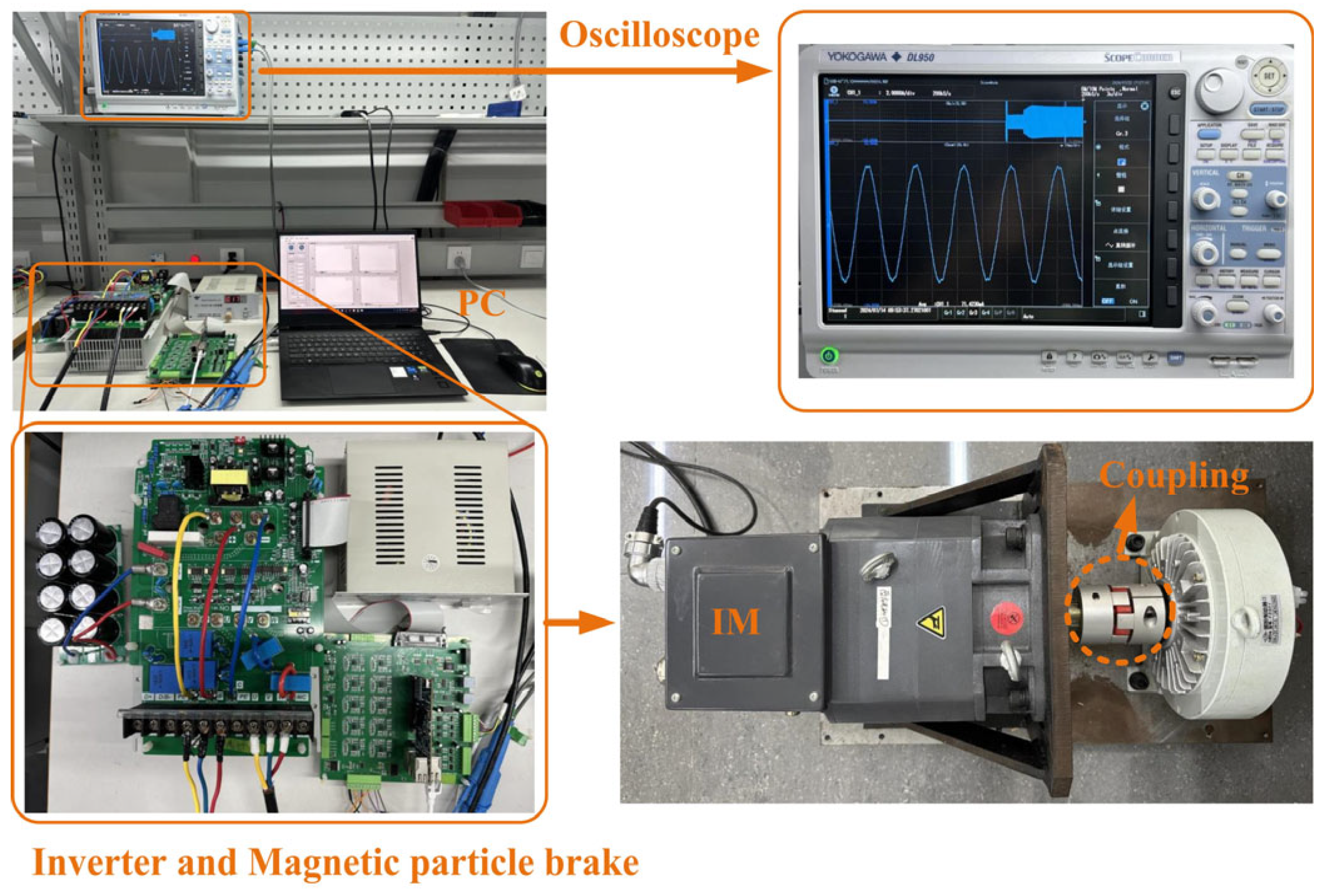
The proposed method for anti-windup of IM under voltage saturation conditions is verified on a rapid control prototype platform based on TMDSCNCD28388D [20]. Figure 8 shows the photograph of the experimental platform. The Lab View-based host-PC interface of the platform enables the observation and recording of all internal variable values in each control cycle. The SVPWM switching frequency is 5 kHz. Due to safety concerns, the maximum voltage of the system is set to 155 V to limit the maximum speed of the PMSM. On this basis, the base speed is 750 rpm. The parameters of the IM are given in Table 2. Table 3 shows the summary of experimental hardware and configuration parameters.

5.1. Acceleration Process Under Precise Orientation

Figure 9 illustrates the differences in system response when accelerating from 810 rpm to 1500 rpm under precise magnetic field orientation, comparing scenarios with and without implementing the proposed method. Figure 9 highlights that the step acceleration leads to a rapid increase in i s q r e f and u ref (amplitude of the reference voltage vector). Notably, before u f d b is adjusted to u s max by the FW controller, significant voltage overshoot occurs, resulting in voltage saturation and decreased response capabilities for i s d and i s q . In Figure 9a, using the traditional method, it takes 90 ms for the actual i s d , q values to match the reference values, reaching a voltage amplitude peak of 3.13 p.u. Conversely, in Figure 9b, the proposed method reduces the feedback current’s response time to 58 ms, which is 35% faster than the traditional approach. Additionally, the peak voltage fluctuation is reduced to 1.91 p.u., a 38.98% decrease compared to the traditional method. This demonstrates that the proposed method not only enhances the current response speed but also effectively mitigates voltage saturation and accelerates the voltage desaturation process, ensuring a smoother and more efficient performance.

5.2. Acceleration Process Under Inaccurate Orientation

This study increases the stator inductance to twice the actual value to obtain the slip calculation error, so as to test the effect of the proposed method under the wrong field orientation. Figure 10 shows the corresponding comparison of the system from 810 rpm to 1350 rpm using the traditional and proposed methods under the inaccurate orientation.
By comparing (a) and (b) in Figure 10, it can be seen that the current value of the traditional method takes 56 ms to catch up with the reference value, while the proposed method only takes 42 ms, which is 25% shorter. At the same time, the reference voltage amplitude of the traditional method is up to 3.08 p.u., while the proposed method is only 1.99 p.u., which is a reduction of 35.39%, verifying its effectiveness.

5.3. Torque Increase Process Under Inaccurate Orientation

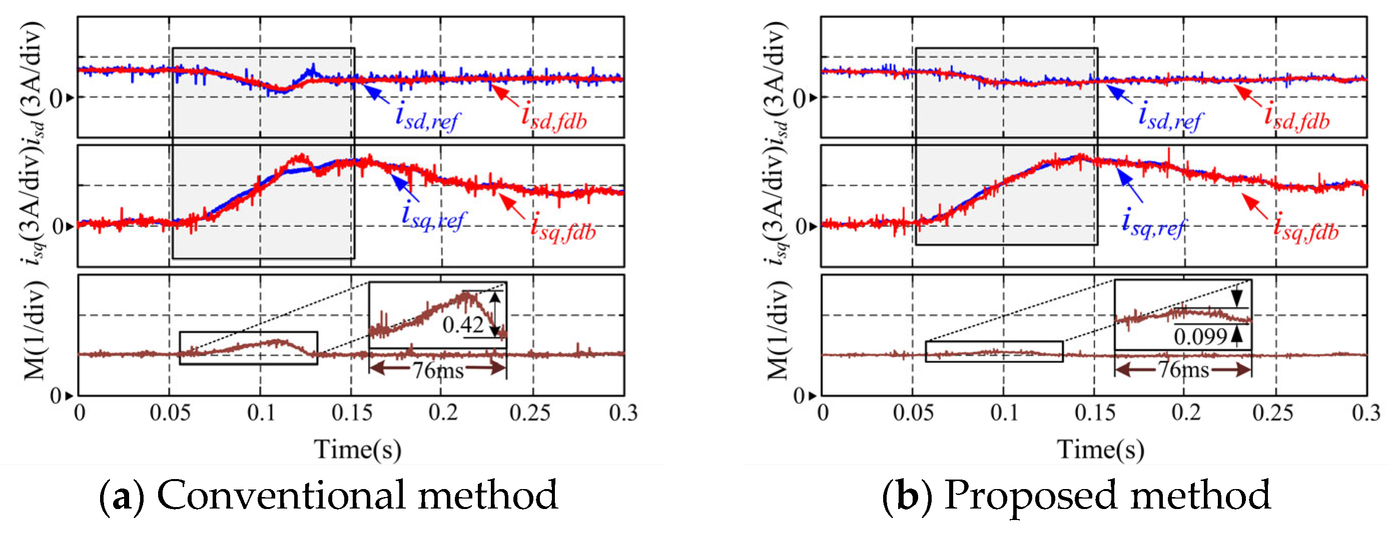
The method is further tested and compared under sudden load conditions. Figure 9 shows the system response with and without applying the proposed method when 80% of the rated load is suddenly added. The operating speed is 1200 rpm (1.6 p.u.).
As can be seen from Figure 11a, the fluctuations in i s d , q and u r e f are significant due to the sudden load. Especially between 0.05 s and 0.15 s, i s d and i s q cannot correctly track the reference value. In the dynamic process, the maximum voltage ripple is 0.099 p.u. when the proposed method is used and 0.42 p.u. when it is not used. The voltage overshoot degree of the proposed method is relatively reduced by 76.4%. In Figure 11b, the voltage saturation degree of the proposed method is significantly reduced, and the current can track the reference value faster.

5.4. Simulation Experiment to Increase Voltage

To further support these conclusions, this study supplements two simulation results of sudden acceleration under precise orientation and sudden load under imprecise orientation, with a maximum voltage of 310 V.
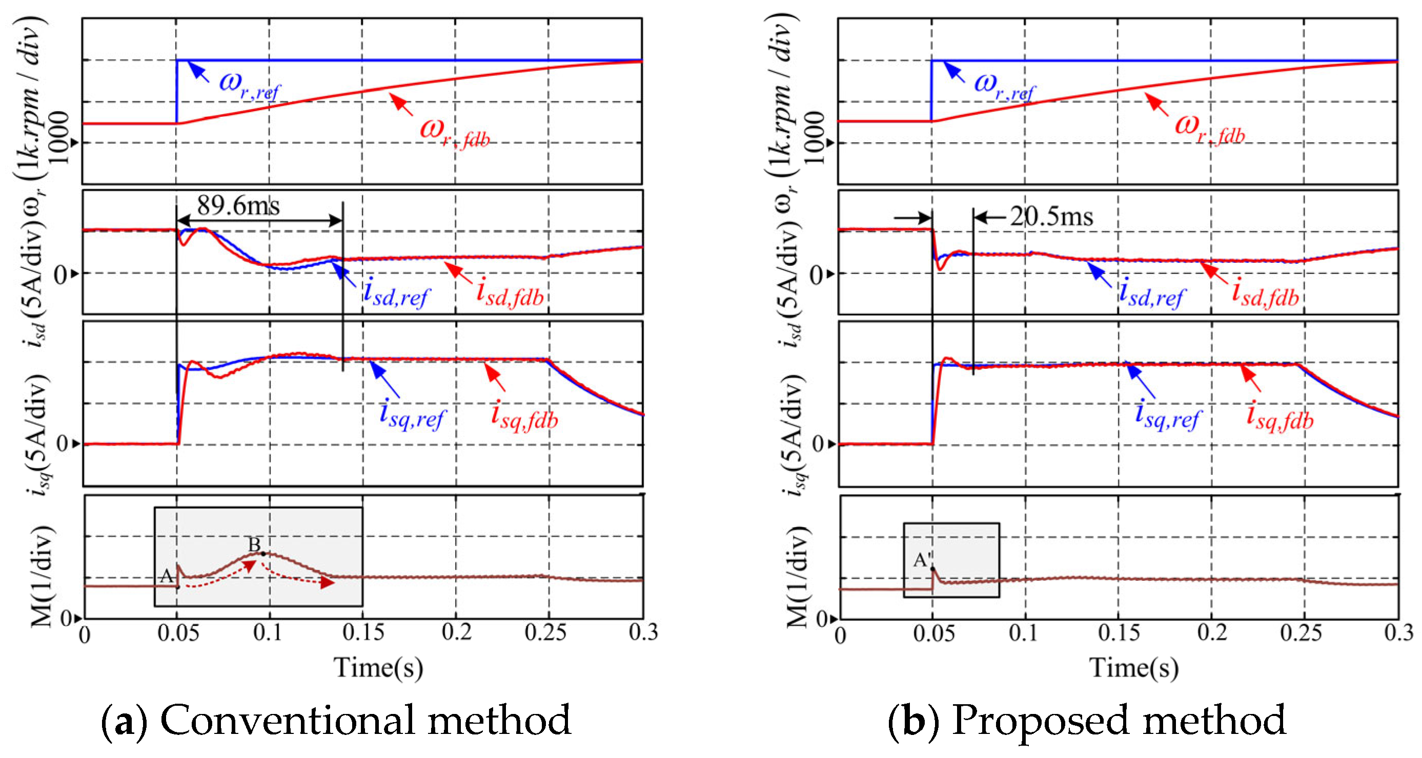
As shown in Figure 12, the system response was compared with and without the proposed method during acceleration from 1500 rpm to 3000 rpm under field-oriented control. Comparative results confirm that the improvements under the 310 V condition are consistent with those observed at 155 V. This demonstrates that even under high-voltage and high-speed conditions, the proposed AFW method enhances current response speed, mitigates voltage saturation, and accelerates voltage desaturation.
At the same time, the comparison results under sudden load were also measured. Figure 13 shows the system response with and without this method when 80% of the rated load is suddenly added. The operating speed is 2400 rpm (1.6 p.u.). In the dynamic process, the maximum voltage overshoot degree is reduced by 67.19% when using the proposed method compared to not using it. Compared to the case where the maximum voltage is 155 V, the voltage saturation of the proposed method is also significantly reduced, with a faster current tracking of the reference value as the maximum voltage rises to 310 V.
Finally, a comparative evaluation of key performance indicators for the proposed AFW method and the conventional method under various working conditions is provided in Table 4.

6. Conclusions

This paper demonstrates that voltage saturation in the flux-weakening region depends on the synchronization control of dq-axis currents and the accuracy of field orientation. Based on these two factors, this paper proposes an AFW control strategy that resists voltage saturation. Experiments have shown that by reducing the traditional FW control delay, the feedback current transient response time during the acceleration process is reduced by 35%, and the peak voltage fluctuation is reduced by 39.98%. In addition, the method compensates for the d-axis current increment due to the orientation lag in the dynamic process. The voltage ripple is reduced by 76.4% under the sudden load. In summary, the proposed AFW method reduces the impact of cascade structure control delay and directional lag on transient performance.
The proposed method still relies on introducing the PI controller into the dynamic process, which can still be optimized and simplified to improve the dynamic performance. In the future, we will focus on the FW method without any PI controller. The breakthrough point is the model predictive control (MPC) scheme. How to apply MPC to FW control is our future development direction. In addition, achieving dynamic performance is more difficult to realize in the overmodulation region than in the linear voltage region. Thus, we will further focus on dynamic optimization in overmodulation.

Author Contributions

Methodology, X.Z.; writing—original draft, X.Z., S.X., and J.Z. All authors have read and agreed to the published version of the manuscript.

Funding

This work was supported in part by Beijing Natural Science Foundation (3244050); in part by Fundamental Research Funds for the Central Universities (2024MS008); in part by the China National Postdoctoral Program for Innovative Talents (BX20230119); in part by China Postdoctoral Science Foundation funded project (2023M741149); and in part by grants from Delta Power Electronics Science and Technology Educational Development Program of Delta Group.

Data Availability Statement

The original contributions presented in this study are included in the article. Further inquiries can be directed to the corresponding author.

Conflicts of Interest

The authors declare no conflicts of interest.

References

  1. Siddiki, A.B.M.I.; Sagor, I.H.; Amin, I.K.; Nasir Uddin, M. Adaptive Super-twisted Sliding Mode Control of Induction Motor for Enhanced Performance. In Proceedings of the 2025 IEEE Industry Applications Society Annual Meeting (IAS), Taipei, Taiwan, 15–20 June 2025; pp. 1–6. [Google Scholar]
  2. De Klerk, M.L.; Saha, A.K. A comprehensive review of advanced traction motor control techniques suitable for electric vehicle applications. IEEE Access 2021, 9, 125080–125108. [Google Scholar] [CrossRef]
  3. Kaewma, P.; Pothi, N.; Kraikitrat, K.; Rakpenthai, C.; Shuraiji, A.L.; Pahasa, J. Robust flux-weakening control approach for threephase induction motor drives. In Proceedings of the 2024 21st International Conference on Electrical Engineering/Electronics, Computer, Telecommunications and Information Technology (ECTI-CON), Khon Kaen, Thailand, 27–30 May 2024; pp. 1–6. [Google Scholar]
  4. Yang, Y.; Song, W.; Wen, R.; Ge, Y. Flux-Weakening Control in an IMC-PMaSynRM System Considering DC Voltage Disturbance. In Proceedings of the 2023 IEEE 2nd International Power Electronics and Application Symposium (PEAS), Guangzhou, China, 10–13 November 2023; pp. 2306–2311. [Google Scholar]
  5. Zhou, Z.; Li, J.; Lu, Y.; Xu, H.; Zhang, Q.; Wu, L. Field Weakening Strategy Extended to Six-Step Operation for Dual Closed-Loop Current Control of Induction Motors. IEEE Trans. Transp. Electrif. 2025, 11, 2674–2683. [Google Scholar] [CrossRef]
  6. Wang, C.; Zhu, Z.Q.; Zhan, H. Adaptive voltage feedback controllers on nonsalient permanent magnet synchronous machine. IEEE Trans. Ind. Appl. 2020, 56, 1529–1542. [Google Scholar] [CrossRef]
  7. Wang, B.; Zhang, J.; Yu, Y.; Zhang, X.; Xu, D. Unified complex vector field-weakening control for induction motor high-speed drives. IEEE Trans. Power Electron. 2021, 36, 7000–7011. [Google Scholar] [CrossRef]
  8. Gashtil, H.; Pickert, V.; Atkinson, D.J.; Dahidah, M.; Giaouris, D. Closed-Loop Voltage Control for Maximizing Inverter Output Voltage in the Field Weakening Region of Induction Machines. IEEE J. Emerg. Sel. Top. Power Electron. 2022, 10, 7514–7526. [Google Scholar] [CrossRef]
  9. Dan, H.; Qian, M.; Wang, H.; Liu, Y.; Sun, Y.; Su, M. Implementation and Stability Analysis of an Improved V/f Induction Motor Control Scheme Based on Constant Rotor Flux. IEEE Trans. Energy Convers. 2024, 39, 1840–1850. [Google Scholar] [CrossRef]
  10. Gulbudak, O.; Gokdag, M.; Komurcugil, H. Model predictive control strategy for induction motor drive using lyapunov stability objective. IEEE Trans. Ind. Electron. 2022, 69, 12119–12128. [Google Scholar] [CrossRef]
  11. Ding, L.; Li, Y.W.; Zargari, N.R. Discrete-time smo sensorless control of current source converter-fed pmsm drives with low switching frequency. IEEE Trans. Ind. Electron. 2021, 68, 2120–2129. [Google Scholar] [CrossRef]
  12. Zhang, D.; Zhou, M.; Wang, C.; You, X. Analysis and applicability comparison of single current regulator methods of pmsm under squarewave mode. IEEE Trans. Ind. Electron. 2024, 71, 1410–1420. [Google Scholar] [CrossRef]
  13. Li, Z.; Xia, J.; Gao, X.; Garcia, C.; Rodriguez, J.; Guo, Y.; Zhang, X. Flux-Weakening Scheme for Four-Switch Inverter-Fed IM Drives with Optimized Overmodulation-Based Modulated Predictive Torque Control. IEEE Trans. Ind. Electron. 2024, 71, 13614–13624. [Google Scholar] [CrossRef]
  14. Gashtil, H.; Pickert, V.; Atkinson, D.J.; Dahidah, M.; Giaouris, D. Improved voltage boundary with model-based control algorithm for increased torque in the field weakening region of induction machines. IEEE Trans. Transp. Electrif. 2021, 7, 1600–1614. [Google Scholar] [CrossRef]
  15. Chen, S.-G.; Lin, F.-J.; Liang, C.-H.; Liao, C.-H. Development of fw and mtpv control for synrm via feedforward voltage angle control. IEEE/ASME Trans. Mechatron. 2021, 26, 3254–3264. [Google Scholar] [CrossRef]
  16. Dong, Z.; Ding, Z.; Wang, B.; Xu, D. Optimized anti-windup coordinating strategy for torque-maximized high-speed flux-weakening operation of constrained induction motor drives. IEEE J. Emerg. Sel. Top. Power Electron. 2022, 10, 2030–2041. [Google Scholar] [CrossRef]
  17. Wang, H.; Gan, C.; Ni, K.; Yu, Z.; Qu, R. Virtual current constraint based segmented trajectory control strategy for flux-weakening operation of spmsm drives. IEEE Trans. Power Electron. 2023, 38, 2262–2274. [Google Scholar] [CrossRef]
  18. Zhang, J.; Zhang, X.; Yu, Y.; Wang, B.; Xu, D. Current redistribution method for induciton motor voltage closed-loop field-weakening control. In Proceedings of the 2023 26th International Conference on Electrical Machines and Systems (ICEMS), Zhuhai, China, 5–8 November 2023; pp. 4055–4059. [Google Scholar]
  19. Hu, Y.; Hua, W.; Hu, M.; Wang, Y. Inductance–Resistance Online Identification for Sensorless High-Speed PMSM Considering Resistive Characteristic of Invertor Nonlinearity. IEEE Trans. Ind. Electron. 2024, 71, 2343–2355. [Google Scholar] [CrossRef]
  20. Zhu, Y.; Zhang, Y.; Kang, J.; Wang, X. Motorast: A low-cost highperformance rapid control prototype platform for electric drives. In Proceedings of the 2023 IEEE International Conference on Predictive Control of Electrical Drives and Power Electronics (PRECEDE), Wuhan, China, 16–19 June 2023; pp. 1–6. [Google Scholar]
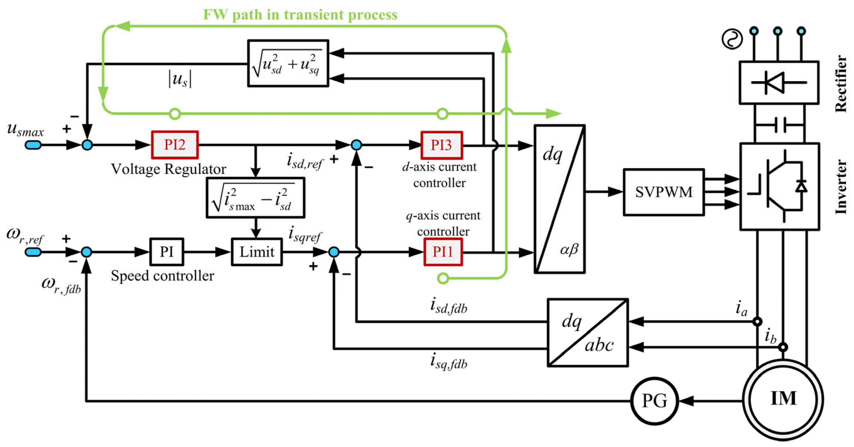
Figure 1. Voltage closed-loop-based flux-weakening scheme.
Electronics 14 03496 g001
Figure 2. Maximum torque output trajectory.
Electronics 14 03496 g002
Figure 3. Changing diagram of current and voltage vectors.
Electronics 14 03496 g003
Figure 5. Auxiliary flux-weakening controller structure diagram.
Electronics 14 03496 g005
Figure 6. Control structure diagram (a) Structure diagram of the proposed method; (b) Simplified structure diagram.
Electronics 14 03496 g006aElectronics 14 03496 g006b
Figure 8. Photograph of the experimental platform.
Electronics 14 03496 g008
Figure 9. Acceleration process from 810 rpm to 1500 rpm under accurate orientation. From top to bottom: rotor speed; reference and feedback values of i s d ; reference and feedback values of i s q ; amplitude of the reference voltage vector. (a) Traditional method; (b) Proposed method.
Electronics 14 03496 g009
Figure 10. Acceleration process from 810 rpm to 1350 rpm under inaccurate orientation. From top to bottom: rotor speed; reference and feedback values of i s d reference and feedback values of i s q ; amplitude of the reference voltage vector. (a) Traditional method; (b) Proposed method.
Electronics 14 03496 g010
Figure 11. System responses under sudden 80% rated load. From top to bottom: reference and feedback values of i s d ; reference and feedback values of i s q ; amplitude of the reference voltage vector. (a) Traditional method; (b) Proposed method.
Electronics 14 03496 g011
Figure 12. Acceleration process from 1500 rpm to 3000 rpm under accurate orientation. From top to bottom: rotor speed; reference and feedback values of i s d reference and feedback values of i s q ; amplitude of the reference voltage vector. (a) Traditional method; (b) Proposed method.
Electronics 14 03496 g012
Figure 13. System responses under sudden 80% rated load. From top to bottom: reference and feedback values of i s d ; reference and feedback values of i s q ; amplitude of the reference voltage vector. (a) Traditional method; (b) Proposed method.
Electronics 14 03496 g013
Table 2. Parameters of the induction machine.
ParameterValueParameterValue
Rated power2.2 kWStator resistance2.74987 Ω
Rated speed750 rpmRotor resistance1.30707 Ω
Maximum voltage155 VStator/Rotor inductance0.157 H
Maximum current9.5 AMutual inductance0.1458 H
Table 3. Summary of experimental hardware and configuration parameters.
CategoryComponentSpecification
Hardware PlatformControl ProcessorTMS320F28335 (32-bit Floating-Point DSP)
development boardTMDSCNCD-28388D
MotorInduction motor (IM)
Load ActuatorMagnetic Particle Brake
Current SensorClosed-loop Hall-effect sensor (LA-50P)
Position/Speed SensorIncremental Encoder (2500 P/R resolution)
Data AcquisitionDL950 Scopecorder (for waveform recording)
HostLabVIEW
Configuration ParametersSVPWM Switching Frequency5 kHz
DC Bus Voltage155 V
Clock frequency of the DSP control board200 MHz
Table 4. Comparison of key FW performance indicators.
U m a x Working ConditionsKey IndicatorsConventional MethodProposed MethodOptimization Degree
155 VAcceleration process under precise orientationcurrent response time90 ms58 ms35%
peak voltage fluctuation3.13 p.u.1.91 p.u.38.98%
Acceleration process under inaccurate orientationcurrent response time56 ms42 ms25%
peak voltage fluctuation3.08 p.u.1.99 p.u.35.39%
Torque increase process under inaccurate orientationmaximum voltage ripple0.42 p.u.0.099 p.u.76.4%
310 VAcceleration process under precise orientationcurrent response time89.6 ms20.5 ms77.12%
peak voltage fluctuation1.39 p.u.1.16 p.u.16.55%
Torque increase process under inaccurate orientationmaximum voltage ripple0.192 p.u.0.063 p.u.67.19%
Disclaimer/Publisher’s Note: The statements, opinions and data contained in all publications are solely those of the individual author(s) and contributor(s) and not of MDPI and/or the editor(s). MDPI and/or the editor(s) disclaim responsibility for any injury to people or property resulting from any ideas, methods, instructions or products referred to in the content.