Review

Driving for More Moore on Computing Devices with Advanced Non-Volatile Memory Technology

1
Department of Electrical Engineering, City University of Hong Kong, Hong Kong, China
2
Yangtze Memory Technologies Co., Ltd., East Lake High-Tech Development Zone, Wuhan 430078, China
3
Hubei Jiu Feng Shan Laboratory, Wuhan 430074, China
*
Authors to whom correspondence should be addressed.
Electronics 2025, 14(17), 3456; https://doi.org/10.3390/electronics14173456
Submission received: 8 July 2025 / Revised: 25 August 2025 / Accepted: 27 August 2025 / Published: 29 August 2025
(This article belongs to the Section Microelectronics)

Abstract

As the CMOS technology approaches its physical and economic limits, further advancement of Moore’s Law for enhanced computing performance can no longer rely solely on smaller transistors and higher integration density. Instead, the computing landscape is poised for a fundamental transformation that transcends hardware scaling to embrace innovations in architecture, software, application-specific algorithms, and cross-disciplinary integration. Among the most promising enablers of this transition is non-volatile memory (NVM), which provides new technological pathways for restructuring the future of computing systems. Recent advancements in non-volatile memory (NVM) technologies, such as flash memory, Resistive Random-Access Memory (RRAM), and magneto-resistive RAM (MRAM), have significantly narrowed longstanding performance gaps while introducing transformative capabilities, including instant-on functionality, ultra-low standby power, and persistent data retention. These characteristics pave the way for developing more energy-efficient computing systems, heterogeneous memory hierarchies, and novel computational paradigms, such as in-memory and neuromorphic computing. Beyond isolated hardware improvements, integrating NVM at both the architectural and algorithmic levels would foster the emergence of intelligent computing platforms that transcend the limitations of traditional von Neumann architectures and device scaling. Driven by these advances, next-generation computing platforms powered by NVM are expected to deliver substantial gains in computational performance, energy efficiency, and scalability of the emerging data-centric architectures. These improvements align with the broader vision of both “More Moore” and “More than Moore”—extending beyond MOS device miniaturization to encompass architectural and functional innovation that redefines how performance is achieved at the end of CMOS device downsizing.

1. A Different Perspective of More-than-Moore and More Moore

The relentless scaling of CMOS (Complementary Metal–Oxide–Semiconductor) transistors has driven the exponential growth of chip integration density—and consequently computing power and overall performance—for decades. This trend, famously known as Moore’s Law [1], has slowed in recent years (see Figure 1), particularly in terms of further reductions in device gate length [2,3,4]. In other words, Moore’s Law, first defined by the continued upscaling of integration levels and later by device miniaturization, is approaching its practical limits. Or in short, we are nearing a time of “no Moore”, i.e., when the CMOS device downsizing will come to an end.
The CMOS community continues to explore every possible avenue to reduce chip footprint and achieve higher integration density, without relying solely on gate length scaling. In fact, for over a decade, scaling rules and technology node definitions have shifted from physical gate length to equivalent gate length representations [5,6]. The introduction of FinFET technology at the 28 nm node marked a significant inflection point, as technology nodes began to be defined by integration density rather than actual gate dimensions. The 3D architecture of FinFETs, along with their increased effective gate width and compact footprint, enables significantly improved chip density [6,7]. To further extend Moore’s Law into the subnanometer era, a host of non-classical, or non-Dennard [8], scaling approaches are being pursued [5]. These include gate-all-around (GAA) and nanosheet transistors, complementary FETs (CFETs), reduced contact and cell sizes, back-side and buried power rails, back-side interconnects, nano-through-silicon vias (TSVs), and advanced stacking or heterogeneous 3D integration techniques (see Figure 1). In a broader context, “More Moore” may be redefined to encompass not only continued reductions in feature size, but also any technologies, structures, configurations, or architectures that enable higher chip density—or deliver better performance—such that the new technology can be equated to a smaller technology node in effect.
Among all technologies, CMOS stands out as uniquely capable of enabling both the smallest physical device sizes, measured in nanometers, and the highest levels of integration, reaching toward tera-scale systems. As such, CMOS will remain the foundation of a wide range of electronic systems: from the smart technologies that shape our lives today to the innovations of the future. Even in a “no Moore” era, CMOS technology will continue to play a pivotal role for decades to come.
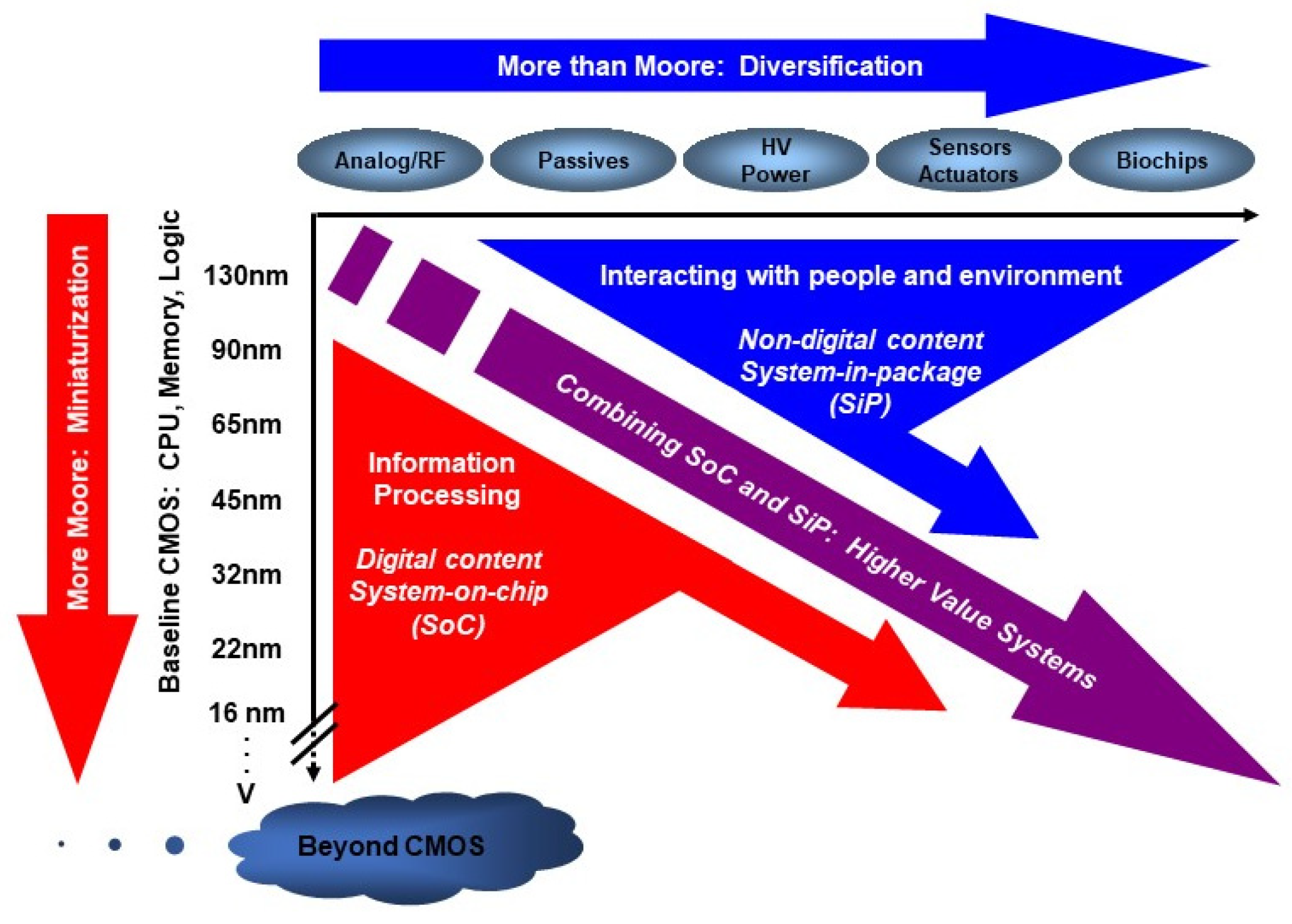
As we transcend the boundaries of traditional digital scaling, new paradigms and applications are emerging that leverage the inherent strengths of CMOS while integrating novel capabilities previously considered beyond its scope. This evolution is captured by the concept of “More Than Moore,” a term introduced by the Semiconductor Industry Association (SIA) and emphasized in the 2010 edition of the International Technology Roadmap for Semiconductors (ITRS) [9]. This original “More Than Moore” concept encompasses a wide spectrum of devices and applications (see Figure 2), including the following:
(a)
RF and analog CMOS circuits for communications and signal processing;
(b)
On-chip integration of passive components such as capacitors and inductors;
(c)
High-voltage and power-management devices for energy control;
(d)
Transducers and sensors capable of detecting and processing physical, chemical, and biological signals;
(e)
Biochips designed for biomedical diagnostics and interfacing with living systems.
Over the past two decades, CMOS technology has expanded well beyond its original role in digital logic, demonstrating remarkable adaptability and success in areas once dominated by other technologies. Notably, CMOS has excelled in RF front-end applications for mobile communication systems [10,11,12,13,14], leveraging continued process scaling to achieve high-frequency performance and seamless integration with digital signal processing on a single chip.
In power electronics, recent breakthroughs in CMOS-based power devices [15,16,17,18], along with the heterogeneous integration of wide bandgap semiconductors such as GaN and SiC, have significantly boosted system efficiency, integration, and flexibility across diverse applications. A particularly promising development is the use of copper bonding to integrate discrete GaN transistors onto CMOS substrates in a low-cost, scalable manner [18,19,20]. These innovations effectively bridge the performance gap between wide-bandgap materials and silicon logic, unlocking new levels of power density and energy efficiency [18].
Various biochips based on CMOS technology have been developed in human-environment interfaces, paving the way for practical applications in healthcare, diagnostics, and biological research [14,21,22]. Furthermore, advances in nanoscale fabrication have extended CMOS’s reach into optoelectronic domains [23,24,25,26,27,28], underscoring its remarkable adaptability across previously unexplored technological frontiers. System-on-chip (SoC) and heterogeneous integration technologies further enrich CMOS capabilities—not only by enabling 3D stacking to achieve higher integration densities within compact 2D footprints, but also by facilitating the incorporation of diverse materials and functional modules beyond the scope of conventional CMOS processes [5,19,29,30,31].
Given its nanoscale dimensions, giga-scale integration density, and the complexity of its manufacturing processes, alongside seven decades of relentless innovation and widespread adoption, it is unlikely that emerging materials and devices will fully replace CMOS shortly [32]. Nevertheless, novel device structures based on 2D materials and advances in atomic-level fabrication techniques are expected to complement CMOS, offering solutions to some of its inherent limitations and potentially enhancing performance in specialized applications [32,33,34,35].
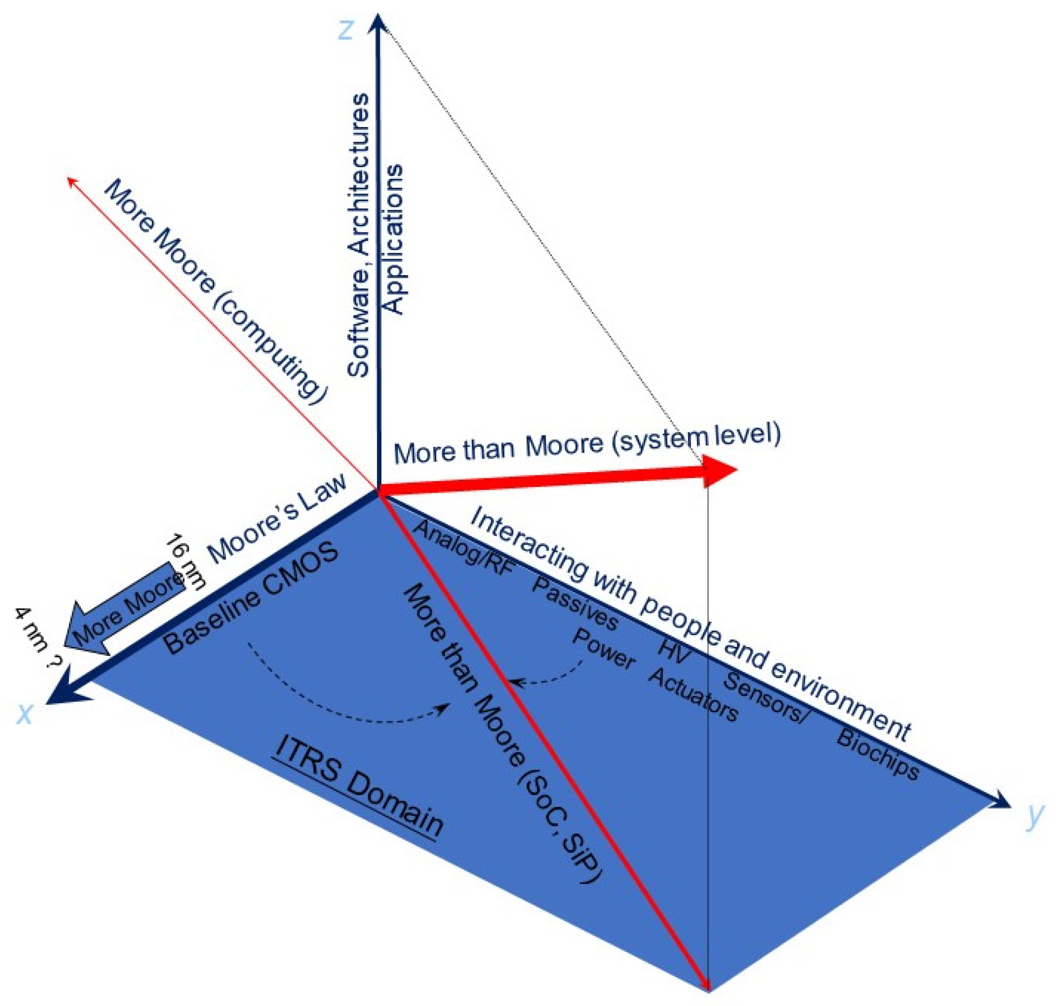
Beyond physical integration through novel materials and technologies, the “More Than Moore” framework must also encompass advances in software, computational architectures, and algorithmic innovation [35]. In 2012, Wong proposed an expanded paradigm combining “More Moore” and “More Than Moore” (see Figure 3) to this domain. In his model, the original “More Than Moore” vision, introduced in the ITRS roadmap, is represented on a two-dimensional plane: CMOS technology scaling (i.e., device downsizing) along the x-axis, and the integration of non-CMOS or non-digital functionalities along the y-axis. This multidimensional integration enhances system capabilities, including improved human–machine interfaces and environmental sensing. Wong’s framework adds a third axis: system-level and application-level innovation. This pillar emphasizes non-hardware elements such as software design, system architecture, domain-specific algorithms, etc. Take computer systems as an example, over the past decade, their performance and capabilities have dramatically improved, not necessarily through transformative hardware, but through developments in networks, the internet, artificial intelligence (AI), and a growing ecosystem of software, tools, and applications. As a result, even with legacy hardware, modern systems are vastly more intelligent, efficient, and responsive than their predecessors. Thus, even as CMOS device miniaturization approaches its physical limits, continued advancements at the algorithmic and system level can still yield more powerful, energy-efficient, and smarter computing platforms [35]. In this sense, not only does “More Than Moore” open the door to new applications, but it also delivers another “More Moore” solution, an effective enhancement of computing power through alternative innovation pathways [4].
Recent advancements in non-volatile memory technologies present compelling opportunities to rethink and reshape computer architectures and computational models. These innovations promise to enable more powerful, energy-efficient systems capable of addressing diverse application scenarios [36,37,38,39,40,41,42]. By fully harnessing the potential of non-volatile memory, we can accelerate the emergence of ubiquitous intelligent systems, support novel computing paradigms, and foster deeper integration between humans and machines. This work offers a forward-looking review of the impacts and future directions of computer system evolution enabled by state-of-the-art non-volatile memory technologies. This review begins by tracing the evolution and key characteristics of leading NVM technologies, examining their physical principles, performance benchmarks, and process compatibility with standard CMOS fabrication in Section 2. In Section 3, the discussion then shifts to the broader impact of NVM across the computing stack, from circuit-level implementations and memory subsystems to overarching system architectures and application domains. At the architectural level, we explore how NVM enables logic-in-memory and processing-in-memory strategies that mitigate the cost of data movement, reduce latency, and improve throughput for data-intensive tasks. At the system level, NVM supports persistent state storage, rapid system boot-up, and greater fault resilience—capabilities that are essential for future computing paradigms, including edge computing, artificial intelligence (AI) engines, and autonomous systems. Section 4 concludes with a summary and final remarks on the technological outlook and potential paradigm shifts in memory-centric computing.

2. Overview of Non-Volatile Memory Technology

Among various non-volatile memory (NVM) technologies, Flash NAND has achieved the most widespread commercial success. It has been integrated into nearly all mainstream digital electronic devices, including mobile phones, digital cameras, SD cards, USB drives, and computers, serving as both large-capacity data storage and embedded memory within system-on-chip (SoC) architectures for low-latency access and system acceleration. Beyond Flash memory, other prominent NVM technologies include Magnetoresistive RAM (MRAM), Resistive RAM (RRAM), phase-change memory (PCM), and Ferroelectric RAM (FeRAM). We shall highlight the core principles and recent advancements of these emerging memory types. Notably, as elaborated in Section 3, NVM technologies are revolutionizing the long-standing von Neumann architecture. Concepts such as near-memory computing, in-memory computing, and neuromorphic computing mark a fundamental shift from reliance on transistor scaling and increased integration density—dominant over the past six decades through CMOS miniaturization—toward architectural innovation that leverages computational algorithms and memory-centric processing. These transformative approaches significantly elevate computing performance and efficiency in the post-MOS era.

2.1. Flash NAND: Another Benchmark of CMOS Technology

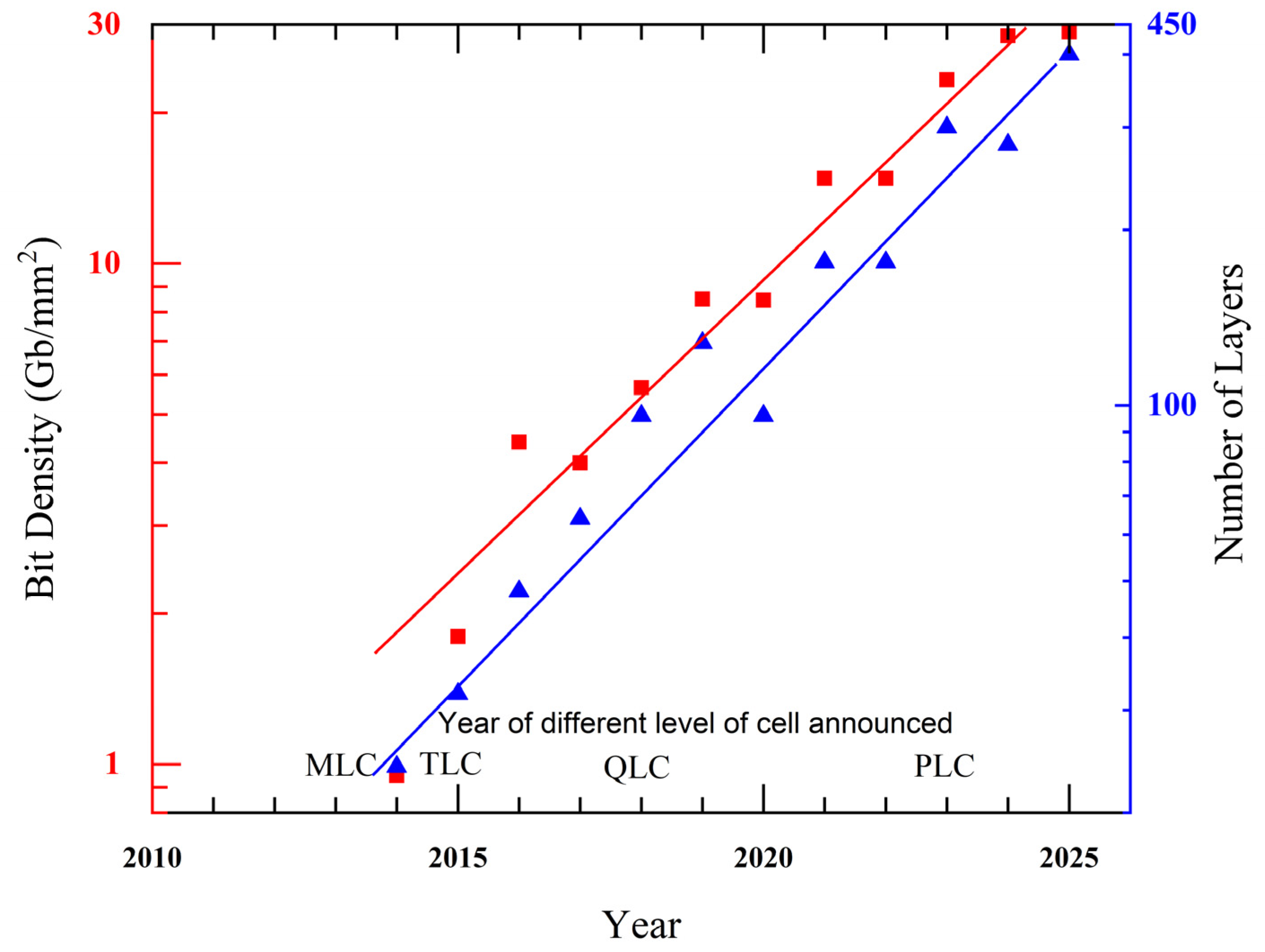
Among various types of non-volatile memory, flash memory—particularly NAND flash—has emerged as the most successful and widely adopted. It leads the field in memory capacity, cost efficiency, and versatility of applications. NAND flash is often regarded as a technological benchmark for semiconductor foundries. Figure 4 illustrates the upward trajectory and technological evolution of flash memory products. Both capacity and bit density closely followed Moore’s Law, which aligns with advancements in the upscaling of integration density of DRAM and CPU. While flash memory typically utilizes technology nodes that are a few generations behind those of leading-edge logic and DRAM devices, its bit density still surpasses the transistor density of DRAM and processors. This is mainly due to continuous innovations in increasing the number of bits per transistor, evolving from single-level cell (SLC), to multi-level cell (MLC), triple-level cell (TLC), quad-level cell (QLC), and most recently, penta-level cell (PLC) technologies. Moreover, flash memory exemplifies cutting-edge progress in vertical stacking technology. The latest products have stacked more than 400 layers, setting new benchmarks for scalability and integration [43].
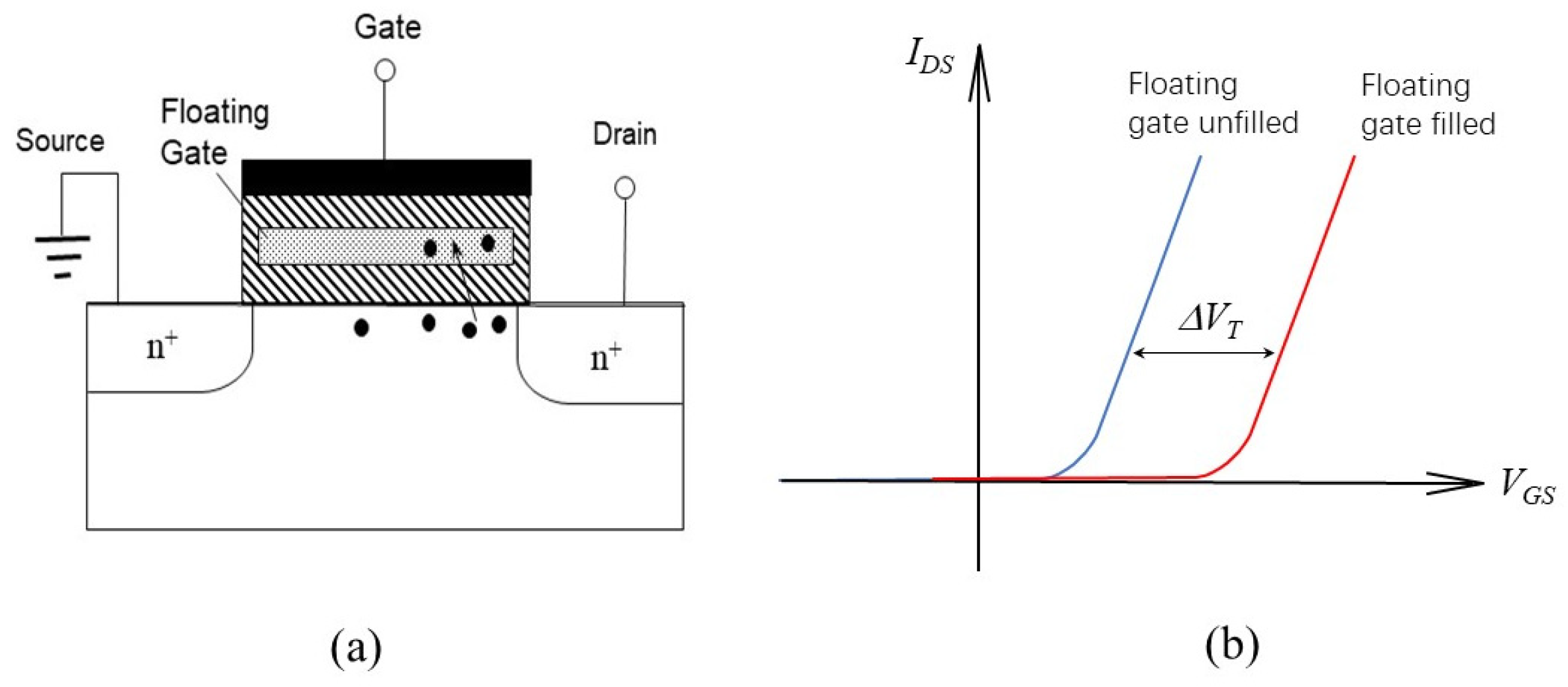
Flash memory evolved from Electrically Erasable Programmable Read-Only Memory (EEPROM), in which each bit consists of one access/programming transistor and one memory transistor. Its core operating principle is based on the Floating Gate (FG) MOS transistor (see Figure 5). Data are stored by trapping charge on the electrically isolated Floating Gate, which alters the transistor’s threshold voltage. The erase operation in early EEPROMs required high voltage, resulting in low-density and inconvenient operation, which is overcome by reducing both the channel length and the thickness of the tunneling oxide in the memory transistor, enabling lower voltage erasure and improved efficiency. A major breakthrough came in 1984 when Masuoka introduced the concept of flash writing [44]. He proposed arranging multiple memory transistors into a bank configuration, allowing them to share a single access transistor. This design brings the system closer to achieving one transistor per bit, and in subsequent generations, it enables storing multiple bits per transistor. The early version of flash memory, both single-layer cell (SCL) and multi-layer cell (MLC), was based on the 22 nm planar CMOS technology. In planar NAND flash memory, the per-cell capacity is constrained by the 4F2 area limit, where F denotes the feature size of the fabrication process. Vertical stacking is necessary to overcome this restriction and achieve greater storage density. Additionally, storing multiple bits per cell is another key strategy to enhance overall memory capacity. One of the earliest architectural implementations of vertical stacking in flash memory was the stacked-surrounding gate transistor (S-SGT) structure. This design utilized polysilicon as the Floating Gate (FG) material and incorporated two memory cells within a single silicon pillar. By reducing the per-bit area by more than 50%, the S-SGT structure enabled commercial production of flash memory devices with capacities of up to 64 Gb [45].
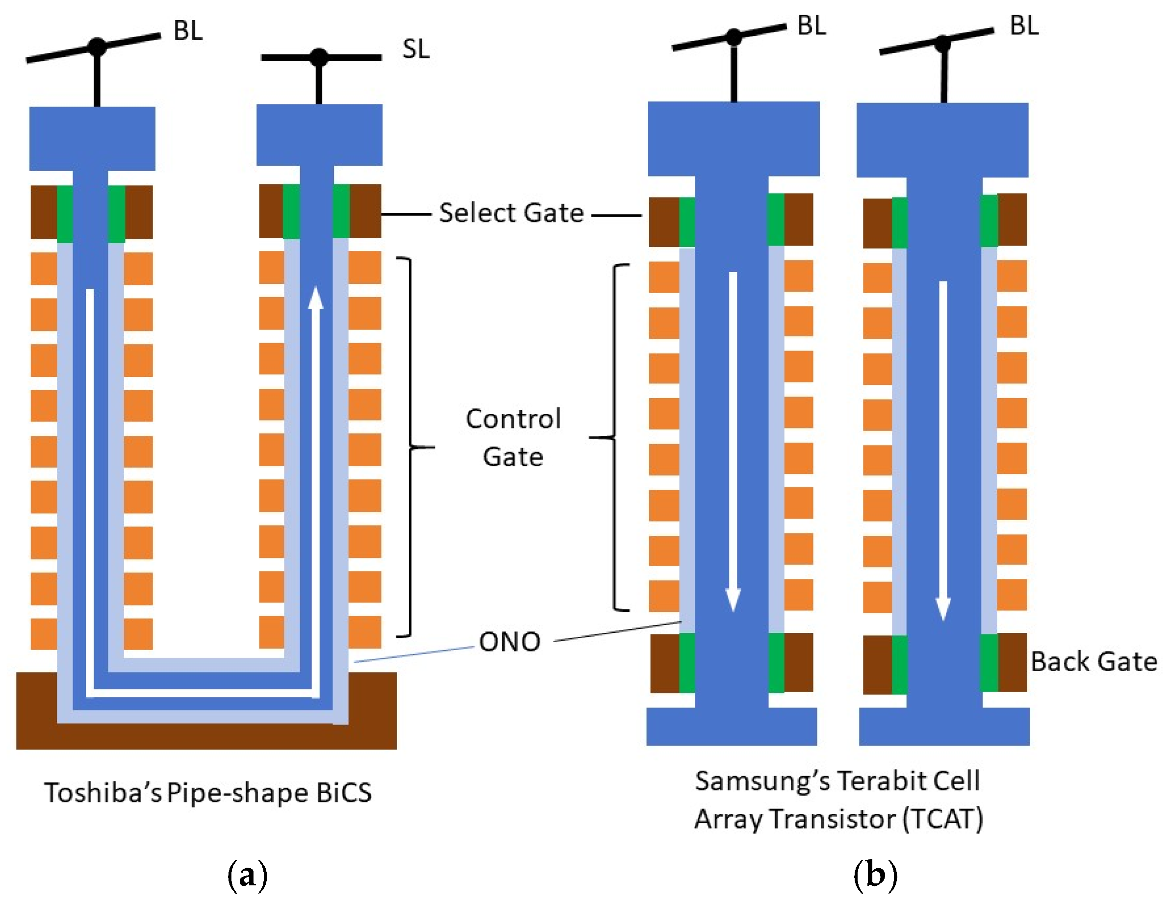
Interest in three-dimensional memory transistor structures dates back to 2001, when Endoh et al. introduced the S-SGT concept, an innovation demonstrating the feasibility of 3D Floating Gate architectures [45]. A pivotal advancement came in 2007, when Toshiba unveiled its 3D Bit-Cost Scalable (BiCS) technology [46]. BiCS replaced conventional Floating Gates with charge-trapping layers composed of materials with a deeper bandgap, deposited via low-pressure chemical vapor deposition (LPCVD). This approach facilitated cost reduction by utilizing a fixed number of critical lithography steps, irrespective of the number of stacked layers [46]. In 2013, BiCS further evolved into pipe-shaped BiCS (p-BiCS), as shown in Figure 6a [47]. This iteration connected adjacent vertical NAND strings at the substrate level, forming a U-shaped channel. The p-BiCS architecture addressed high source line resistance and improved data retention by minimizing tunnel oxide damage during fabrication. Additionally, the shared source line was directly connected to a metal grid, significantly reducing parasitic resistance. Around the same period, Samsung developed a gate-replacement process to mitigate charge loss due to lateral diffusion. This innovation was branded as Terabit Cell Array Transistor (TCAT) technology for its 3D V-NAND products (see Figure 6b) [48]. Leveraging TCAT architecture, Samsung successfully commercialized its 128 Gb 2-bit/cell 3D V-NAND product in 2014.
Process innovations have played a pivotal role in scaling 3D NAND technology. Cell-to-cell parasitic capacitance rises sharply as technological nodes shrink and stack heights increase. This degrades the coupling ratio between the Floating Gate (FG) and the Control Gate (CG), impacting memory performance. To counter this challenge, the Extended Sidewall Control Gate (ESCG) structure was introduced [49]. By incorporating additional shielding components, ESCG significantly enhances CG coupling. Reports show that ESCG enables a 20% reduction in program/erase (P/E) voltage, a 5% increase in read current at the 30-nm node, and a 50% decrease in interference compared to traditional FG NAND cells [48]. The Dual Control Gate with Surrounding Floating Gate (DC-SF) architecture was developed to enhance capacitive coupling further. This design integrates a surrounding FG with vertically stacked dual CGs, enabling low-voltage operation (15 V/−11 V) and offering a broad P/E window of 9.2 V. Such characteristics make it suitable for quad-level cell (QLC) operation, supporting 4 bits per cell. This innovation was instrumental in commercializing terabit-scale NAND flash memory in the early 2010s [50]. Meanwhile, adopting a gate-last fabrication approach has significantly improved write cycle endurance by reducing electrical stress on critical dielectric layers [51]. The evolution of 3D NAND continued with the Separated-Sidewall Control Gate (S-SCG) structure. This design pairs a cylindrical FG with a linear CG, achieving the highest CG coupling ratio reported to date and eliminating cell-to-cell interference. S-SCG cells support low-voltage operations −15 V programming at threshold voltage (Vth) of 4 V and 7 V erase at Vth = –2 V, offering a read current margin more than 1.5 orders of magnitude greater than prior designs. Its outstanding noise immunity positions the S-SCG structure as a promising candidate for multi-level cell applications [52].
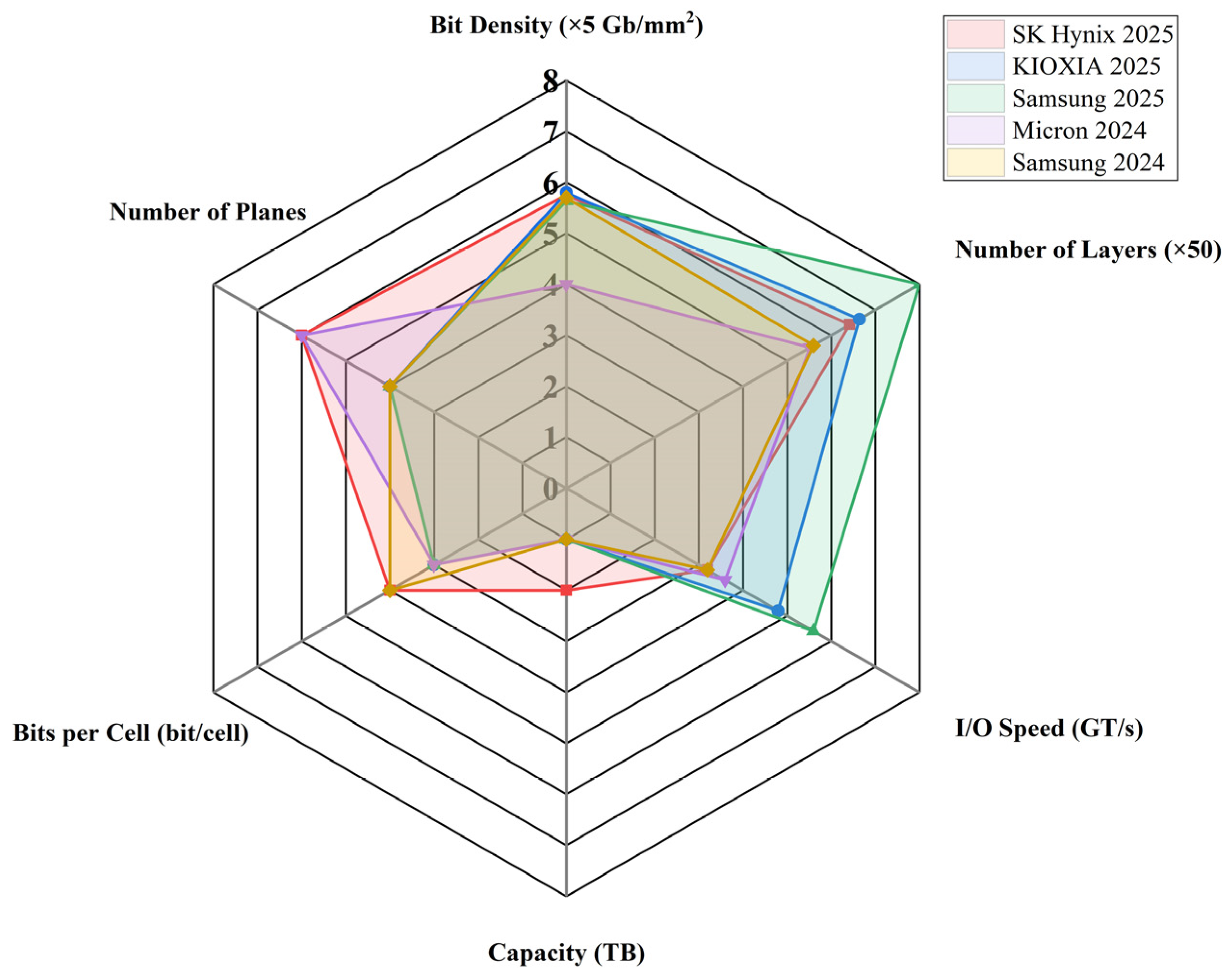
In 2023, penta-level cell (PLC) technology emerged, marking a significant milestone in flash memory scaling. The latest PLC devices incorporated 192 stacked layers, delivering a 1.67 Tb capacity and setting a record with an industry-leading density of 23.3 Gb/mm2 [53]. Samsung announces its latest 1 Tb V-NAND product achieved an unprecedented 400 active layers and a high-speed interface of 5.6 GT/s, pushing the envelope for both vertical scalability and performance [54]. Figure 7 compares the latest NAND products regarding capacity, bit density, I/O speed, and number of vertical stacking layers.

2.2. Resistive Random-Access Memory (RRAM)

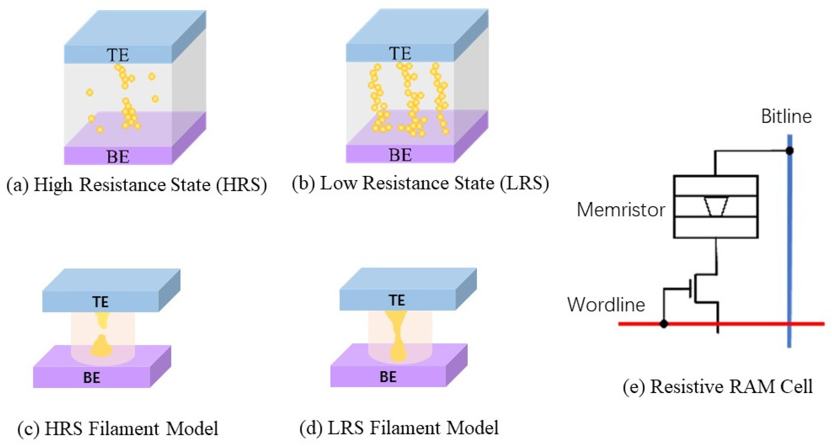
Resistive Random-Access Memory (RRAM) is based on the modulation of dielectric resistance within a metal–insulator–metal (MIM) structure [59]. The resistive switching phenomenon was first reported in the reversible breakdown of thin metal oxide films in the 1960s [60]. Figure 8 illustrates the operating principle. In the initial state, the insulating film typically exhibits a high resistance due to a low concentration of defects such as mobile ions and oxygen vacancies. Nevertheless, a small leakage current may still be detectable as these defects assist in charge conduction (Figure 8a). When a strong electric field is applied across the dielectric, additional defects can be generated and aligned to form continuous conductive paths between the bottom and top electrodes. These low-resistance channels correspond to the low-resistance state (LRS) (Figure 8b). This phenomenon is generally explained using the conductive filament (CF) model, which describes these paths as filaments forming or rupturing depending on the electrical bias. Figure 8c,d illustrate a broken filament (representing HRS) and an intact filament (representing LRS), respectively. By associating the two resistive states with logical values, logic “0” for HRS and “1” for LRS—RRAM enables non-volatile memory functionality. Switching between states is accomplished by applying a voltage above a critical threshold (Set voltage), which drives filament formation or dissolution. Similar to the Dynamic Random-Access Memory (DRAM) architecture (Figure 8e), a MOS transistor can be employed for access control, with the memory element (the switchable resistive device) connected to the drain terminal for data storage.
Many dielectric materials, with different resistance change mechanisms, have been explored as resistive switchable candidates. Because of the various underlying physical processes, different switching characteristics were reported. Two filamentary mechanisms could be involved: Conductive Bridge RAM (CBRAM), which relies on the electrochemical formation and dissolution of metallic filaments using active metals like silver or copper; and Oxide-based RRAM (OxRAM), where oxygen-vacancy filaments are manipulated via redox reactions involving transition metals such as tantalum or titanium nitride [61,62]. Although numerous material systems can exhibit resistive switching, few meet industrial standards for high-density, cost-effective memory, with CMOS compatibility being a central requirement. Binary transition metal oxides like TaOx and HfOx have emerged as leading candidates in this domain [61,62].
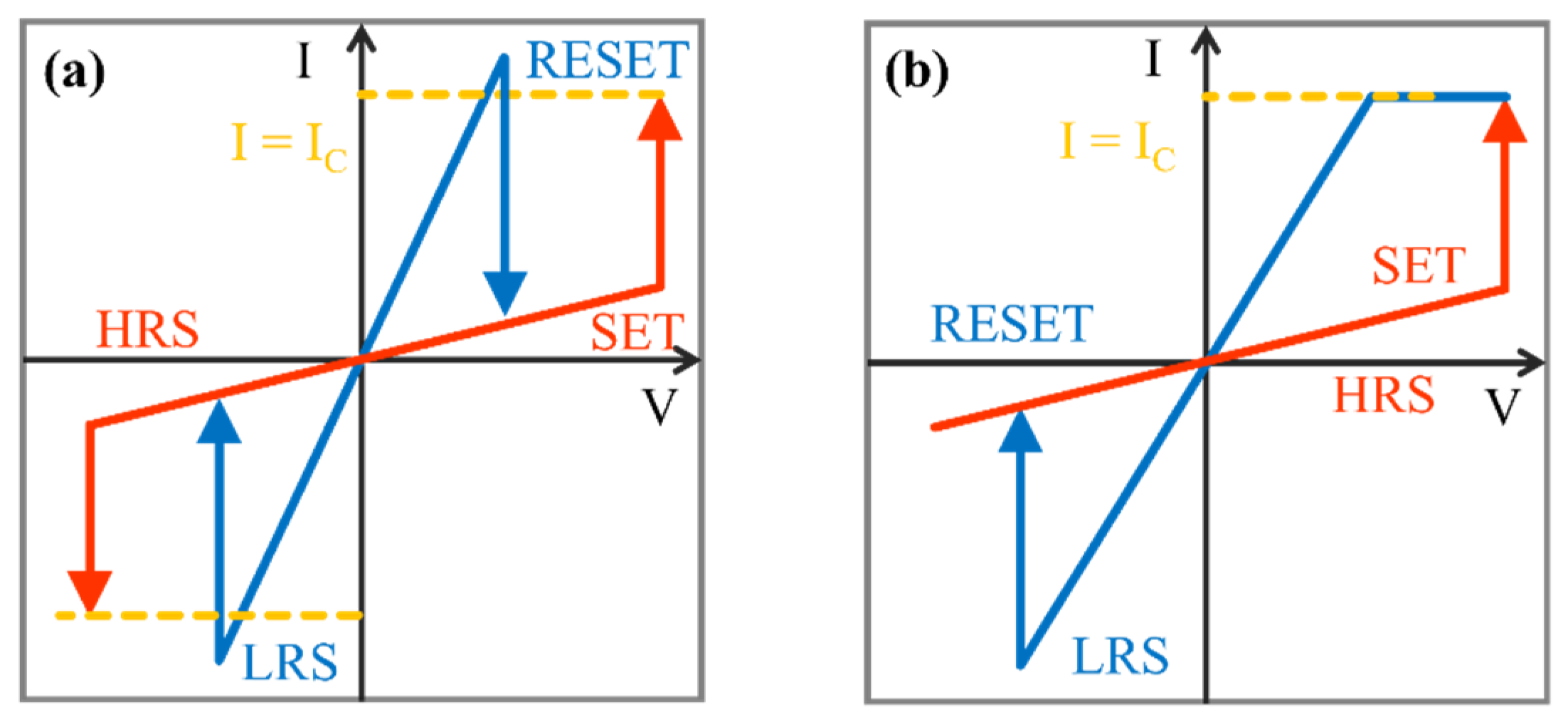
Figure 9 illustrates the voltage-dependent characteristics of two different RRAM: the unipolar and bipolar modes. In a unipolar switching device, SET and RESET actions occur in a single polarity. Figure 9a illustrates the positive switching characteristics. For bipolar mode devices, SET and RESET operations occur in different bias polarities. Unipolar devices usually have lower fabrication costs, making them well suited for oxide-based memristor applications. Conversely, bipolar switching requires alternating voltage polarities, positive for SET and negative for RESET, where the voltage direction triggers the resistance change. This configuration facilitates high-density crossbar integration and is advantageous for emerging applications such as storage-computing convergence and in-memory computing [63].
Figure 10 illustrates key milestones in the development and commercialization of Resistive Random-Access Memory (RRAM). The first commercial product was launched by Samsung in 2004 using 0.18 µm CMOS technology [64]. Panasonic followed in 2013 with the release of an 8-bit microcontroller (MCU) featuring a 2 Mb RRAM array at the 180 nm node, which was subsequently scaled to a 2 Mb chip on a 40 nm node by 2015. By 2024, RRAM had been widely adopted at mature process nodes. For instance, TSMC currently offers RRAM integration at 40 nm, 28 nm, and 22 nm nodes [65,66], and has recently achieved a significant milestone by fabricating the largest-capacity commercially available 32 Mb RRAM chip using 12 nm ultra-low-power FinFET technology [67]. Although its transistor footprint (6F2) is relatively large compared to competing technologies, many RRAM devices are reported to be fully compatible with CMOS processes. Additionally, three-dimensional (3D) stacking presents a viable pathway for achieving higher-density architectures. These advancements underscore the significant scalability and commercialization potential of resistive memory technology.
RRAM is almost fully compatible with the mainstream CMOS fabrication processes, positioning it as a leading candidate for embedded memory in advanced nodes. RRAM offers exceptional scaling advantages due to its localized resistive switching, which is largely independent of cell area. They deliver outstanding features such as ultra-high-density integration, nanowatt-level ultra-low power consumption, millisecond-scale switching speeds, and exceptional endurance. In the embedded memory space, shrinking process nodes have posed increasing challenges for conventional flash memory, leading to greater fabrication complexity and higher production costs. Figure 11 illustrates the simple crossbar array structure and the 3D stacking structure for high-density in-memory applications [63]. Furthermore, RRAM’s inherent non-volatile nature enables the retention of learned synaptic weights even after power loss, making it a compelling candidate for neuromorphic systems [68,69].

2.3. Magnetic Random-Access Memory (MRAM)

Magnetic Random-Access Memory (MRAM) is widely regarded as a promising successor to SRAM and DRAM in next-generation in-memory computing systems, thanks to its high switching speed and low energy consumption. It introduces a new paradigm in non-volatile memory technology by combining high-speed operation (~10 ns), almost unlimited endurance (>1015 write cycles), near-zero standby power consumption, and instantaneous data retention [70,71,72]. The core mechanism behind MRAM is the tunneling magnetoresistance (TMR) effect, which occurs in a structure known as a magnetic tunnel junction (MTJ). An MTJ consists of two ferromagnetic layers separated by a thin insulating barrier. As illustrated in Figure 12, the tunnel current’s magnitude depends on the relative magnetization direction of these two layers, yielding different electrical resistance values depending on whether the magnetizations are parallel or anti-parallel.
The magnitude of the TMR effect is defined as follows:
M R   r a t i o = R a p R p R p
where R a p is the electrical resistance while the magnetization direction of the two ferromagnets in anti-parallel mode. R p is the electrical resistance while the magnetization directions are parallel.
The tunneling magnetoresistance (TMR) effect was first discovered in 1975 by Jullière in Fe/Ge-O/Co junctions at 4.2 K, where a MR ratio of approximately 14% was recorded [73]. Miyazaki later made significant advancements in enhancing the TMR effect. Especially in 1994, Miyazaki achieved an improved MR ratio of 18% for an experiment using iron junctions separated by an amorphous aluminum oxide insulator [74]. A major breakthrough occurred in 2004 when Parkin and Yuasa independently demonstrated TMR ratios exceeding 200% at room temperature using Fe/MgO/Fe junctions [75,76], marking a critical step toward practical applications. Later in 2008, Ikeda and Ohno’s research group reached unprecedented TMR values of 604% at room temperature and over 1100% at 4.2 K using CoFeB/MgO/CoFeB junctions. These accomplishments established a robust foundation for contemporary MRAM development [77,78,79,80].
In MRAM, data are stored by modulating the magnetization states of Magnetic Tunnel Junctions (MTJs). Each memory cell adopts a 1S1M architecture, comprising a selector transistor and a cross-point MTJ. As illustrated in Figure 13, the MTJ’s operation hinges on the magnetization direction of its free layer (indicated by a red arrow) relative to the fixed reference layer. When these layers are aligned in parallel, the MTJ exhibits low resistance; when anti-parallel, high resistance, thereby enabling binary data encoding. This design facilitates ultra-high-density memory arrays, with a theoretical cell area as small as 4F2.
Several MRAM variants have been developed over time, each employing distinct magnetization switching mechanisms. Field-MRAM, the earliest architecture, relies on magnetic fields generated by current-carrying wires to alter the magnetization state of the memory cell [78]. Although Field MRAM is simple and reliable, it faces significant limitations in scalability. Its design results in high write power consumption and susceptibility to inter-cell interference, which hinders its integration into high-density memory arrays.
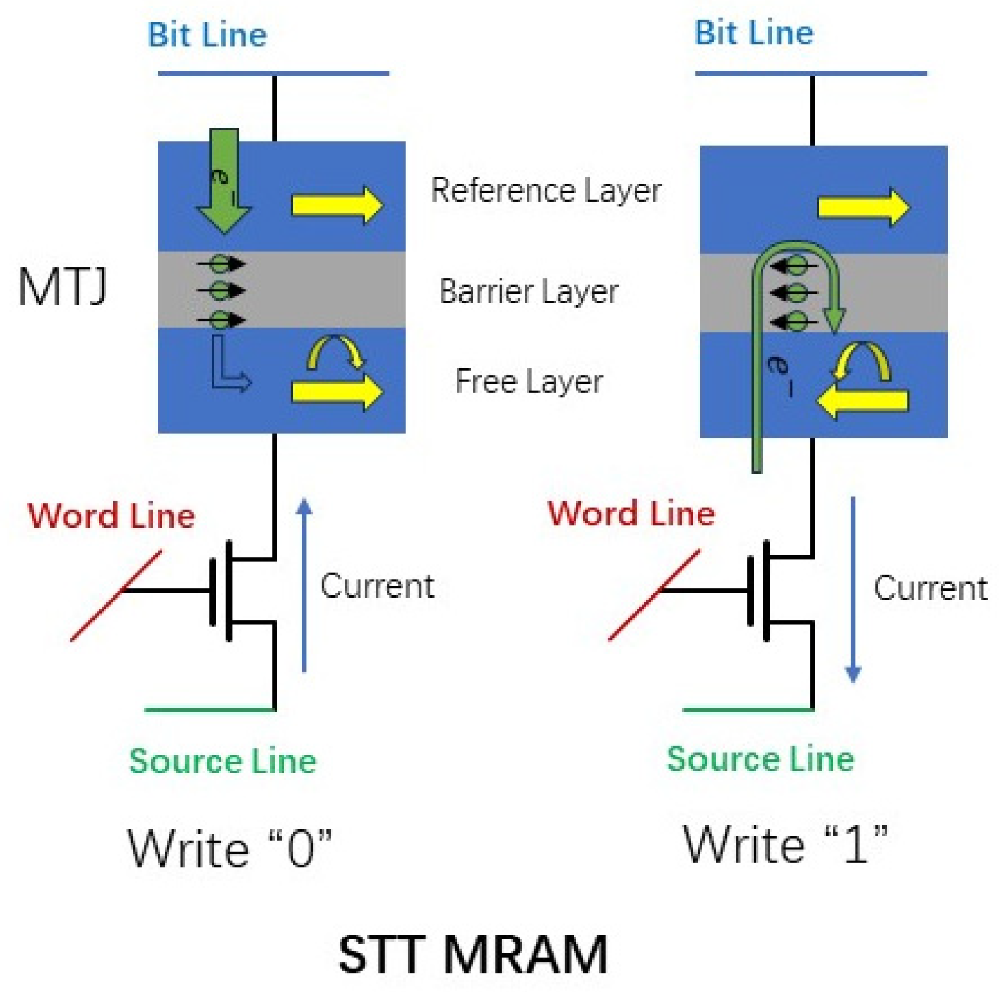
The second generation, Spin-Transfer Torque MRAM (STT-MRAM), was conceptualized by Slonczewski and Berger in 1996, and later demonstrated experimentally by researchers at Cornell University in 2005. STT-MRAM introduces a more refined switching mechanism by utilizing spin-polarized current to generate spin-transfer torque (see Figure 13). As electrons tunnel through the MTJ’s insulating barrier and interact with localized magnetic moments, they exert a torque capable of reversing the magnetization of the free layer, provided the current exceeds a critical threshold. This innovation led to reduced write energy and better scalability compared to Field-MRAM.
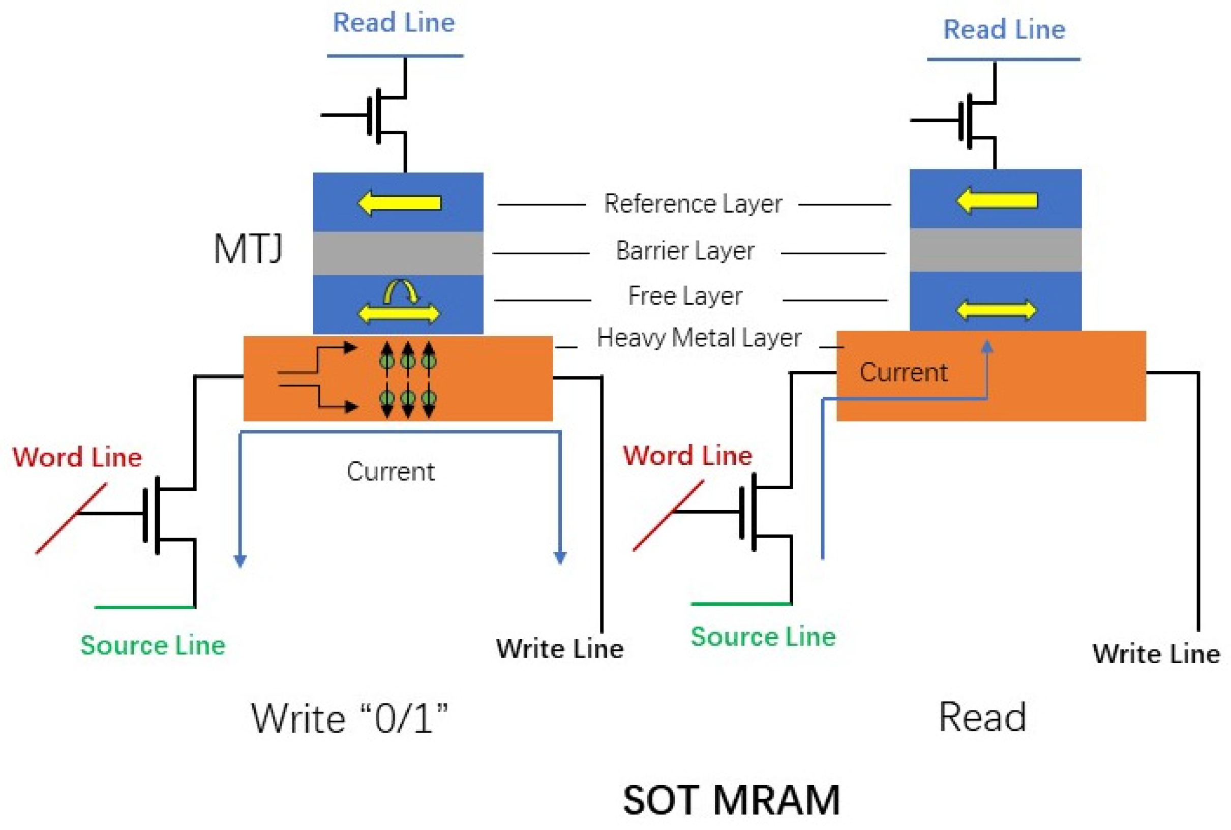
The most advanced variant to date is Spin–Orbit Torque MRAM (SOT-MRAM), representing the third generation of the technology. Unlike STT-MRAM, SOT-MRAM employs in-plane current within a neighboring heavy metal layer to produce Spin–Orbit Torque, thereby switching the free layer’s magnetization without channeling high current directly through the MTJ. As illustrated in Figure 14, this separation of current paths significantly lowers write disturbance and enhances device endurance. SOT-MRAM offers several performance advantages, including GHz-level switching speed, ultra-low switching energy below 100 fJ/bit, exceptional endurance beyond 1015 write cycles, and minimal standby power. These strengths are further amplified by engineering refinements such as synthetic antiferromagnetic (SAF) layers and voltage-assisted switching, making SOT-MRAM highly scalable and compatible with CMOS technology.
Despite its advantages, MRAM still trails behind other nonvolatile memory technologies in terms of raw storage capacity. This situation has changed. A 64-Gigabit (Gb) MRAM chip has just been achieved by the Kioxia group, which features a dense 1S1M layout and ultrafast three-nanosecond read pulses [81]. SOT-MRAM is also considered CMOS-compatible and can potentially be integrated into semiconductor processes through modified Back-End-of-Line (BEOL) steps. However, this integration faces challenges due to the complexity and sensitivity of the ultra-thin magnetic layers involved in the MRAM stack. Additionally, MRAM’s thermal stability remains a key concern, directly influencing its Tunnel Magnetoresistance (TMR) ratio and long-term reliability. Overcoming these obstacles will be crucial for large-scale deployment and adoption across computing platforms.

2.4. Ferroelectric RAM (FeRAM) and FeFET

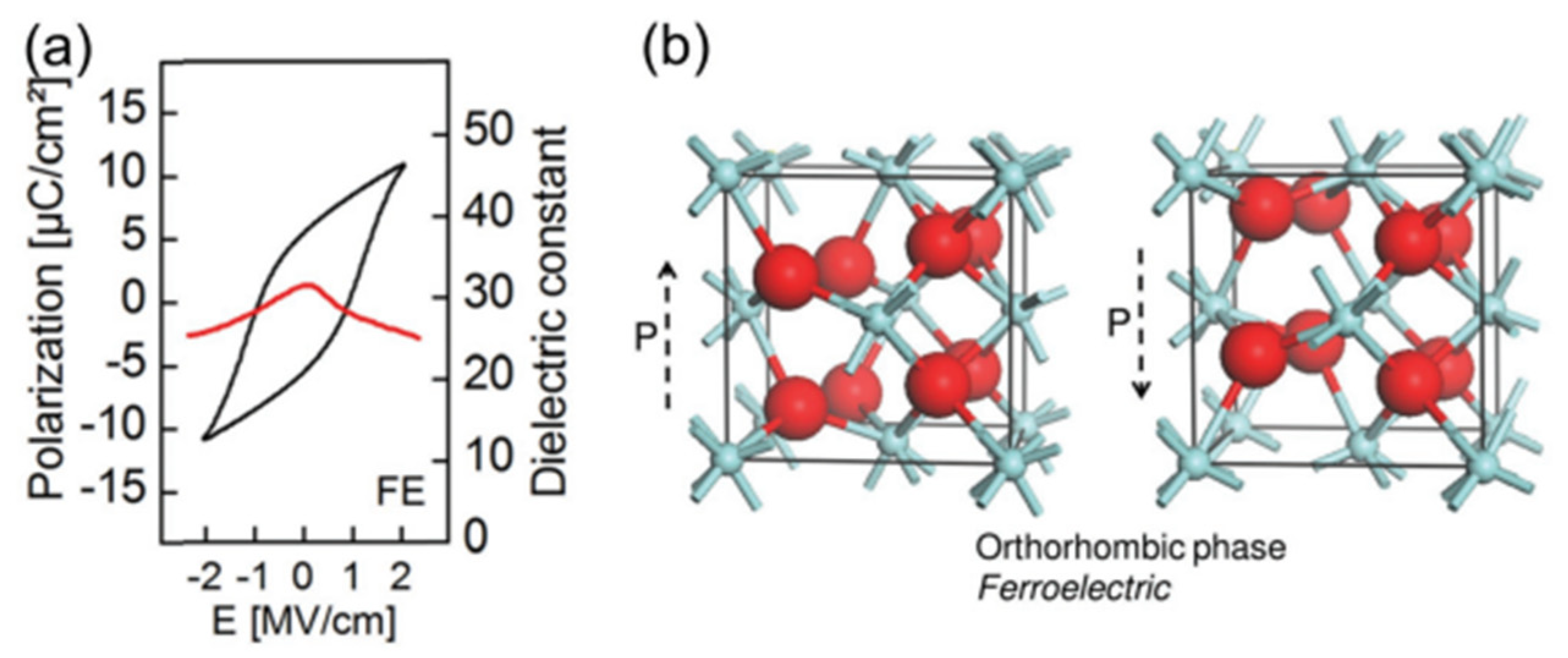
Ferroelectric memory technologies, including Ferroelectric RAM (FeRAM) and Ferroelectric Field-Effect Transistors (FeFET), are non-volatile memory types that leverage the physical principle of ferroelectricity, first discovered in the 1920s [82]. In ferroelectric materials, polarization arises from the displacement of positive and negative charge centers, and this polarization can be reversed by applying an external electric field without exceeding the material’s breakdown voltage. Once polarized, the material maintains its state even after the external field is removed, thanks to the stability of its internal ion arrangements. This remanent polarization forms the basis for data storage and is typically detected by measuring reversal or non-reversal currents.
Ferroelectric materials belong to a subset of pyroelectric crystals. While a polarization–electric field (P–E) hysteresis loop is indicative of ferroelectric behavior, it does not conclusively prove ferroelectricity; similar effects, such as charge relaxation in electrets, can produce misleading signatures. Two primary classes of ferroelectric compounds dominate memory applications: perovskite structures like lead zirconate titanate (PZT) and layered perovskites such as strontium-bismuth-tantalate (SBT). PZT offers favorable crystallization temperatures (450–650 °C), making it more compatible with CMOS Back-End-of-Line (BEOL) processing. In contrast, SBT is lead free and more resistant to polarization fatigue but demands significantly higher crystallization temperatures (~750–850 °C), complicating its integration.
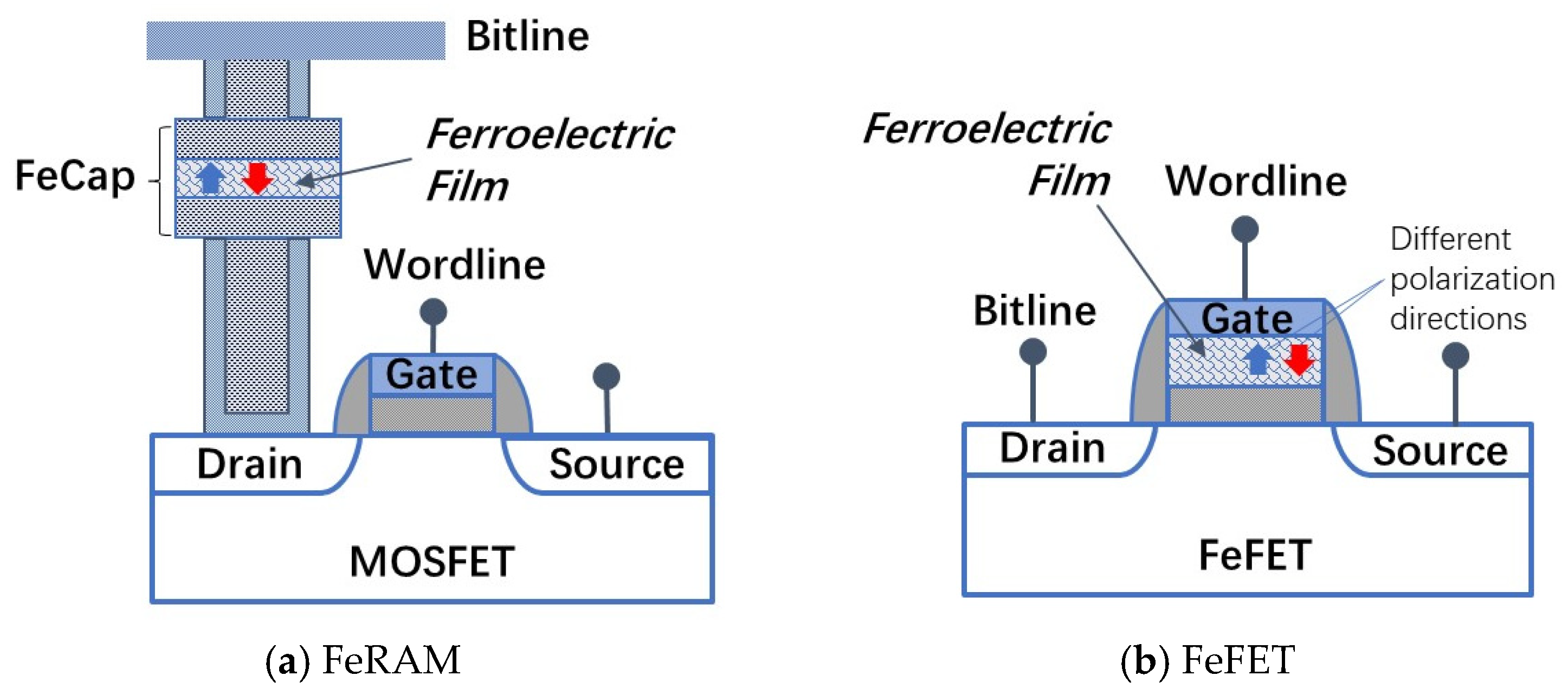
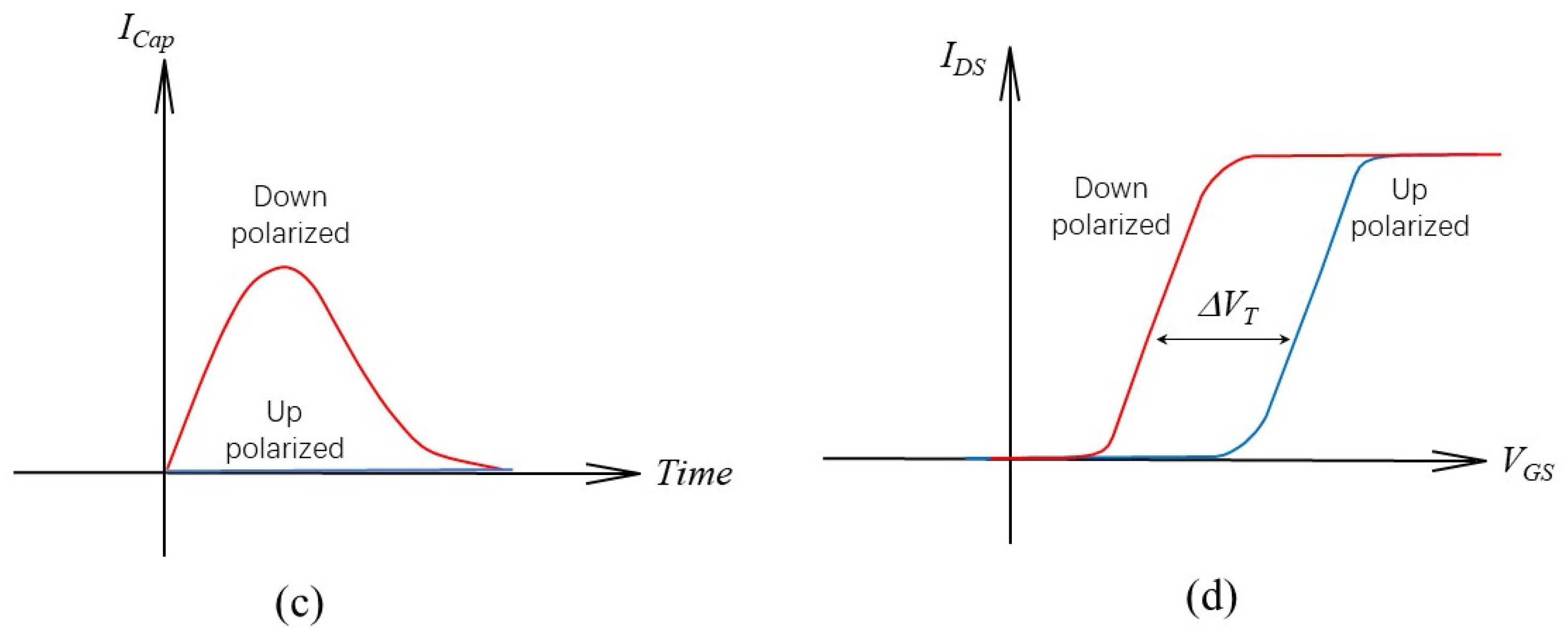
FeRAM devices typically adopt either a one-transistor–one-capacitor (1T1C) architecture, analogous to DRAM but with a ferroelectric capacitor, or a simplified one-transistor (1T) configuration with ferroelectric material as the gate dielectric (see Figure 15). Programming involves activating the word line and applying voltage pulses between the bit and source lines to manipulate the capacitor’s polarization direction resulting from the crystal structure (see Figure 16). Although this mechanism reliably stores binary data, it suffers from a destructive readout process that necessitates data rewriting after each read cycle. Miniaturizing FeRAM cells presents a major challenge, as smaller geometries complicate the accurate sensing of polarization-induced charge. Additionally, integrating ferroelectric materials and compatible electrode interfaces remains complex, particularly when scaling to 3D memory architectures.
Ferroelectric Field-Effect Transistors (FeFETs) offer a more scalable alternative, incorporating a ferroelectric layer into the gate of a conventional MOSFET. Unlike FeRAM, where data are read by charge detection, FeFETs operate based on how polarization influences the transistor’s electrical characteristics. A voltage pulse reverses the ferroelectric polarization, inducing charge in the transistor’s channel and switching it to the “on” state, representing a logic “1” without requiring continuous gate bias. FeFETs boast advantages such as non-destructive readout, improved scalability, and compatibility with standard CMOS logic. However, traditional ferroelectric materials like PZT and SBT face scaling limitations: their low coercive fields and high permittivity amplify depolarization effects and necessitate thicker films to preserve functionality.
Recent advancements in ferroelectricity within doped hafnium oxide (HfO2) have significantly renewed interest in FeRAM and FeFET technologies [83,84]. HfO2 offers ideal properties for ultra-scaled memory: a wide bandgap (~5.3 eV) and strong band offset with silicon to suppress gate leakage, along with a high coercive field (~1 MV/cm) and modest permittivity (~30), ensuring strong data retention and wide memory windows even in nanometer-scale films. Notably, HfO2 is fully compatible with advanced CMOS fabrication processes and is already used as a gate dielectric in high-k metal gate (HKMG) technology. It can be precisely deposited via atomic layer deposition (ALD), making it especially suitable for integration into dense 3D NAND memory. Nevertheless, challenges persist around voltage scalability and the mitigation of depolarization effects, which directly impact endurance and long-term retention reliability.

2.5. Phase-Change Memory (PCM)

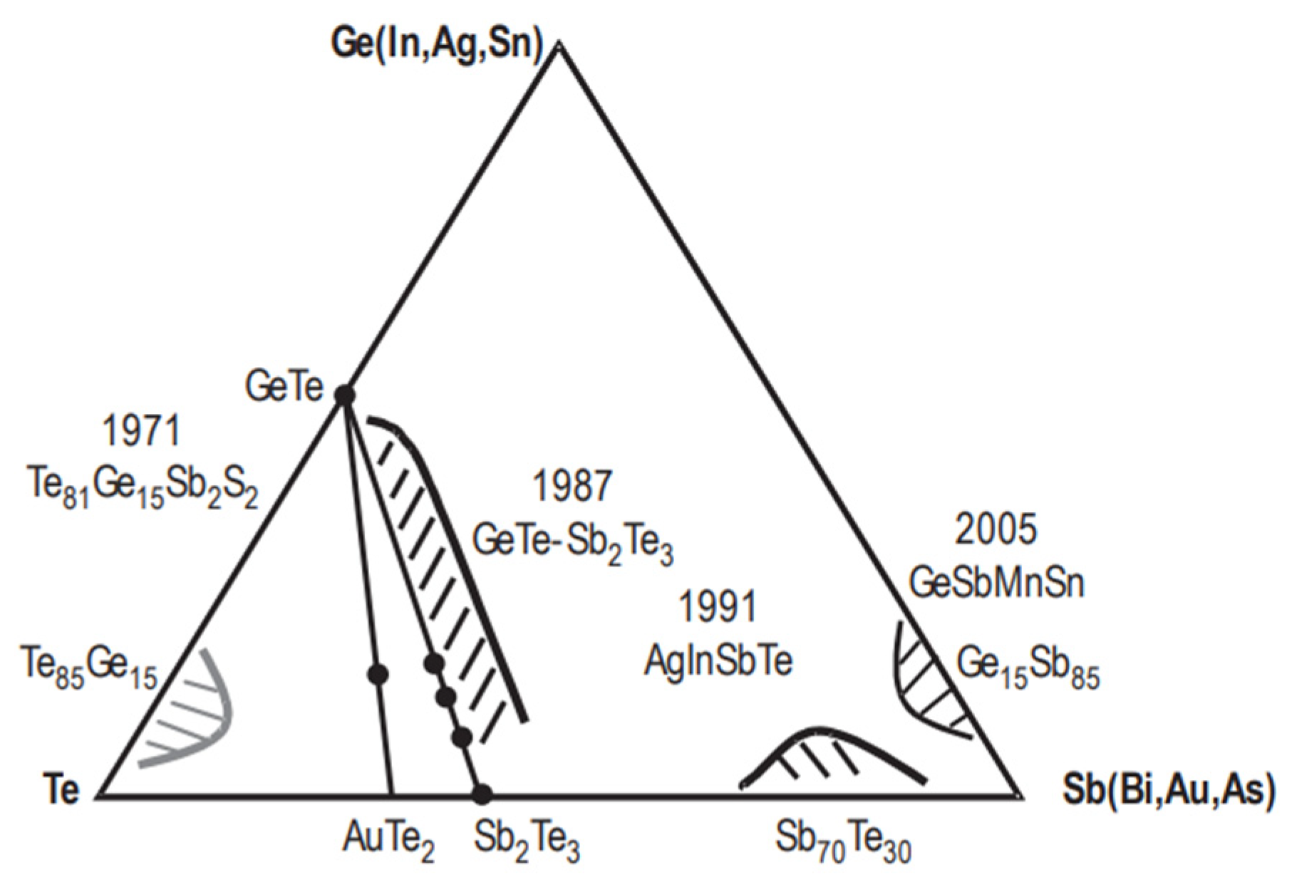
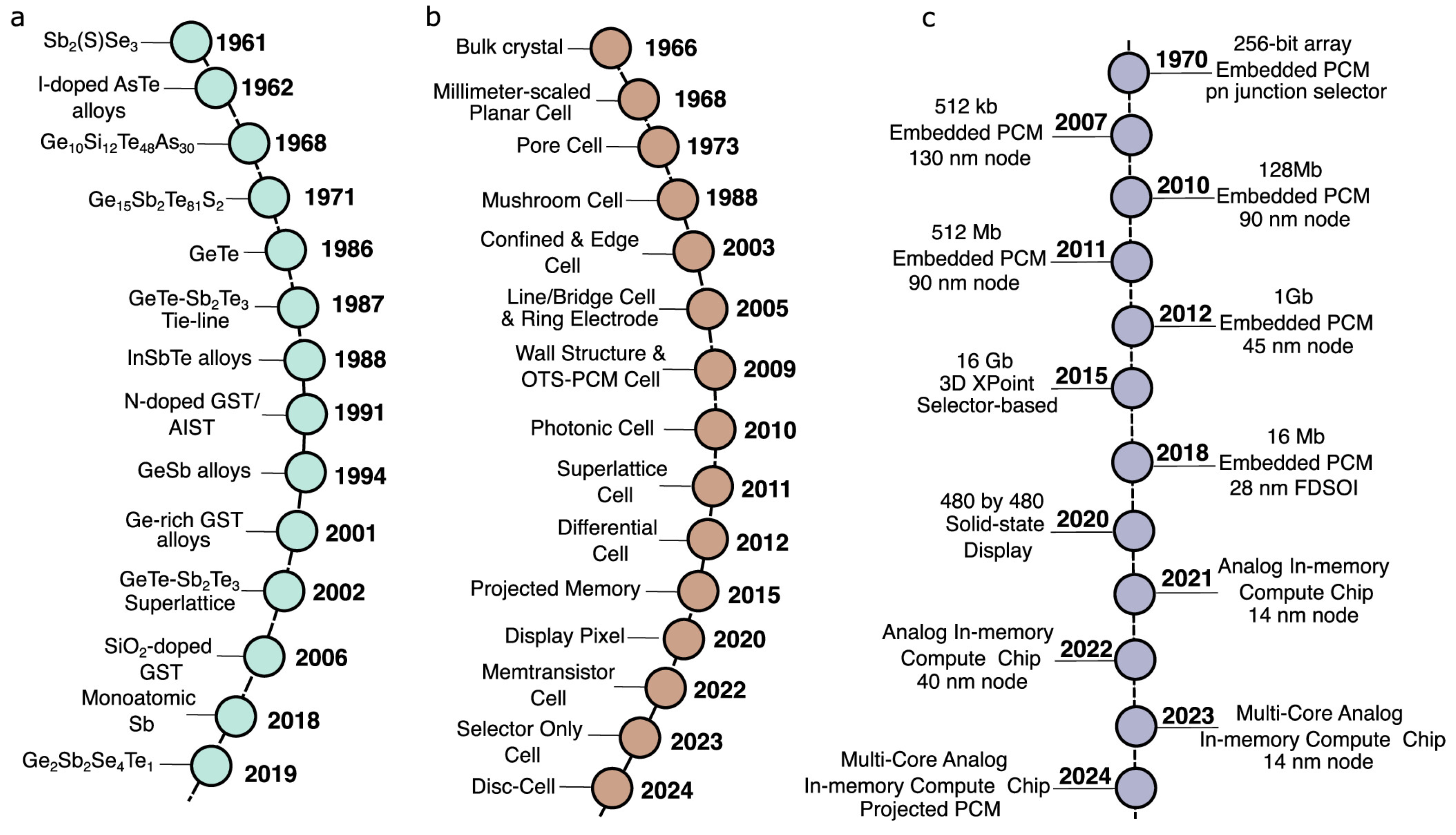
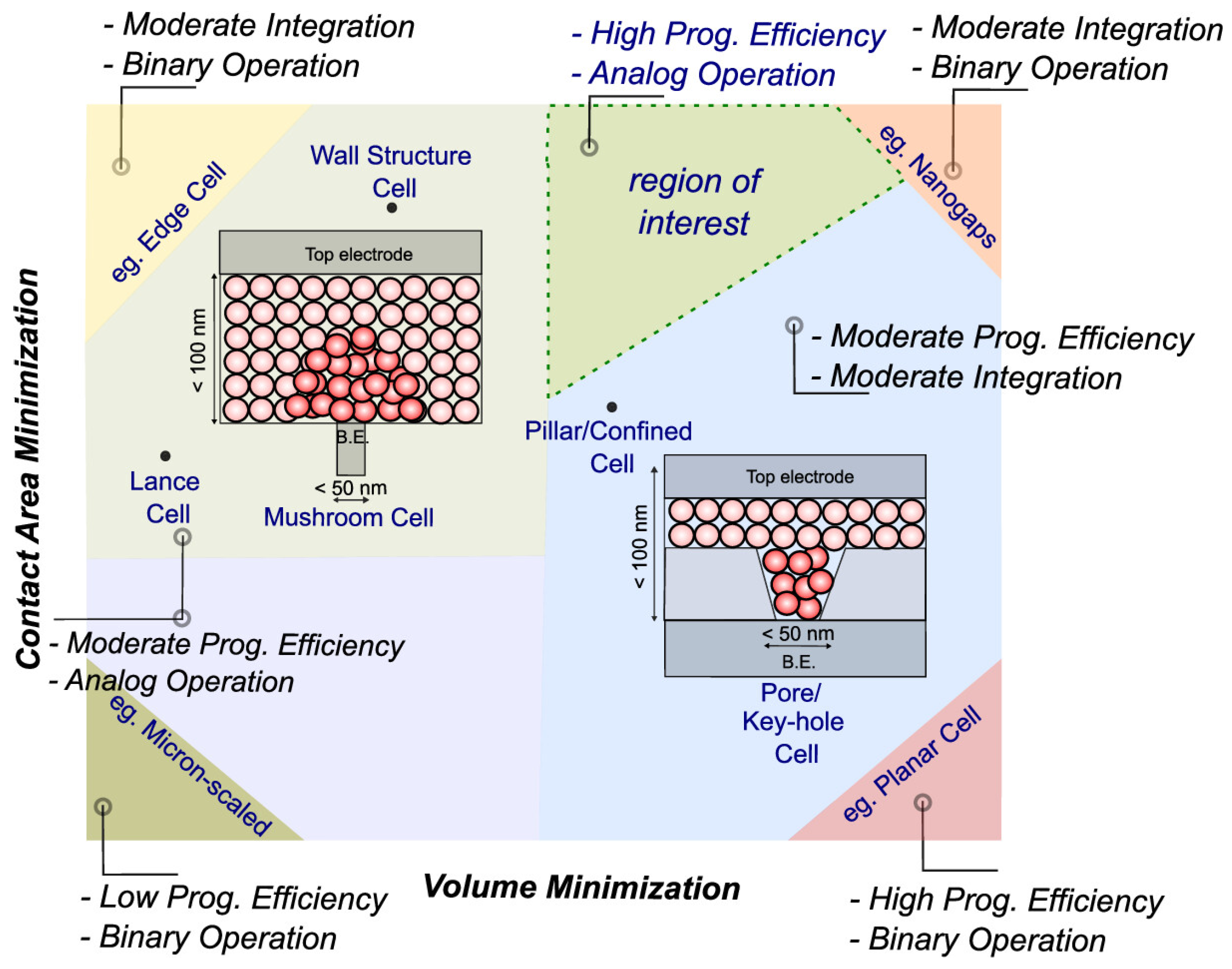
Phase-change memory (PCM) has progressed over the past five decades from fundamental research to commercial deployment, with strong potential as storage-class memory and neuromorphic hardware [85,86,87,88]. Its operation hinges on the rapid and reversible phase transition of chalcogenide materials between amorphous (high-resistance) and crystalline (low-resistance) states. This mechanism enables PCM to deliver non-volatility, fast read/write speeds, high endurance, scalability, and multi-level data storage. The concept dates back to the 1960s, when Ovshinsky investigated phase transitions in chalcogenide glasses. In 1968, he demonstrated reversible switching using tellurium-based compounds (Ge10Si12As30Te48), establishing the basis for PCM [89]. However, early challenges—such as high operating voltages, limited endurance, and sluggish switching—combined with immature microelectronic processes, delayed practical adoption. Contemporary PCM materials include pseudo-binary germanium-antimony-tellurium compounds situated between GeTe and Sb2Te3, such as Ge2Sb2Te5, GeSb2Te4, and Ag4In3Sb67Te26 (AIST) (see Figure 17) [90,91,92,93]. These offer rapid switching, stable phase states, and long data retention, exceeding ten years at room temperature, with reliable phase control at nanosecond speeds. Over the years, the core structure of phase-change memory (PCM) devices has evolved into various architectures centered around a “heating electrode–phase-change material–electrode” unit designed to enable localized and efficient phase transitions. Syed, Gallo, and Sebastian have presented a comprehensive review on the technology evolution in the aspect of material development, device structure variation, commercial products, and applications (see Figure 18) [94]. Key PCM device configurations include mushroom-shaped cells, confined cells, μ-trench structures, side-contact cells, cross-spacer layouts, asymmetric electrodes, and ring-shaped microelectrodes [88,94,95,96,97,98]. All share a common goal: minimizing the contact area between the phase-change material and electrodes to enhance switching efficiency.
Among these, the mushroom-shaped and confined cell structures (see Figure 18) are the most widely adopted, owing to their relatively straightforward fabrication and integration. In mushroom-shaped devices, the bottom electrode is embedded within insulating holes to restrict its size, thereby reducing the contact interface with the phase-change material. In contrast, confined structures deposit the phase-change material itself inside insulating holes, retaining it within a narrow volume. Typically, a tungsten or titanium nitride bottom electrode contacts a thin layer of phase-change material—often Ge2Sb2Te5 (GST)—through a small via. When current flows through this constricted region, Joule heating triggers phase transitions in the material above. Thermal dissipation differs significantly between structures: mushroom-shaped cells predominantly dissipate heat through the bottom electrode, while confined cells direct most heat through the surrounding dielectric. Although the confined design simplifies integration, its thermal efficiency still requires optimization.
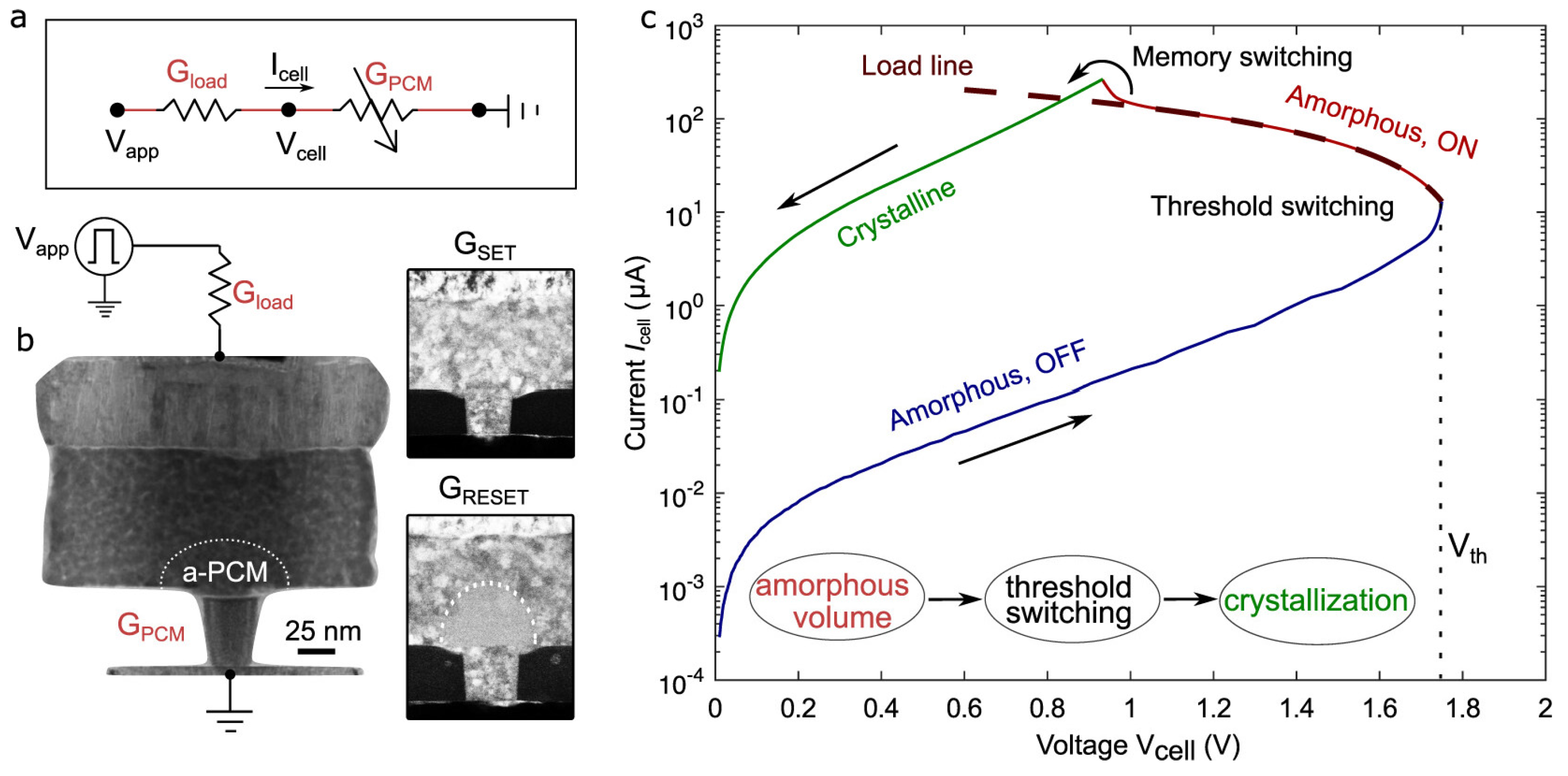
The core operating principle of phase-change memory (PCM) involves Joule heating, which facilitates the rapid, reversible transition of the phase-change material between the amorphous and crystalline states. The crystalline phase features a long-range ordered atomic arrangement and lower free energy, corresponding to the low-resistance state (LRS). In contrast, the amorphous phase consists of a disordered atomic structure with higher free energy, resulting in the high-resistance state (HRS). By applying electrical pulses under specific conditions, the memory cell can be switched between these states for data storage [90,92,93,99]. In the RESET operation, a short-duration, high-amplitude electrical pulse rapidly heats the phase-change region above its melting point (Tm). When the pulse ends, the molten material undergoes ultra-fast quenching (cooling rates >109 K/s), preventing atomic rearrangement and locking the material into the amorphous phase, which exhibits resistivity in the megohm range. The SET operation uses a longer, lower-amplitude pulse to heat the region above its crystallization temperature (Tc) but below Tm. Sustained heating allows atoms in the amorphous phase to reorganize into the crystalline state, yielding resistivity in the kilohm range. Figure 19b illustrates the change of PCM in SET and RESET modes, and the current-voltage characteristics are illustrated in Figure 19c. For READ operation applies a low sensing voltage or current—well below the SET and RESET thresholds—to measure the cell’s resistance non-destructively. By evaluating the measured resistance, the stored data are identified as either the HRS (amorphous) or LRS (crystalline) state.
Despite its attractive attributes—non-volatility, fast speed, and scalability—phase-change memory (PCM) faces several technical challenges that hinder wide-scale commercialization [85,91,100]. Key issues include high power consumption during RESET operations, resistance drift in the amorphous state that affects data retention and multi-level cell (MLC) reliability, limited endurance due to material degradation, thermal crosstalk in dense arrays, and scaling difficulties that disrupt switching uniformity at nanoscale dimensions. To address these hurdles, extensive research has focused on material engineering, device design, and system-level optimization. Various materials have been explored (see Figure 18 and Figure 20). Doping Ge-Sb-Te (GST) alloys with elements such as C, N, O, Si, Ti, and Bi has improved phase stability, crystallization kinetics, resistivity contrast, and endurance [101,102,103,104,105,106,107]. Notably, Sc-doped Sb-Te alloys significantly lowered RESET currents (~90%) and accelerated switching due to favorable atomic structures [108,109,110]. Novel antimony-rich alloys like Sb-Te and Ge-Sb offer faster crystallization and lower power consumption [103,111,112]. Interfacial PCM (iPCM) using [GeTe/Sb2Te3] superlattices has emerged as a breakthrough, enabling microamp-level programming currents and nanosecond switching through interface-controlled phase transitions [110,113,114,115]. Further performance improvements have been explored via advanced electrode materials (e.g., TiTe2, TiOx), innovative layouts (e.g., tapered and ring-shaped electrodes), and robust conductive barrier layers (e.g., TiN, TaN) to enhance thermal isolation and interface reliability [116,117,118,119,120,121].
PCM typically employs a one-transistor–one-resistor (1T1R) architecture, where a MOSFET regulates access to a PCM cell. Data are stored by toggling between crystalline (“1”) and amorphous (“0”) states, sensed through resistance measurements. A major milestone came with the 2017 release of Intel and Micron’s 3D XPoint (Optane), based on doped-GST and ovonic threshold switch (OTS) selectors in a 1S1R configuration, delivering near-DRAM speeds, high endurance, and dense 3D integration [122]. Ongoing advances in materials (doping, alloys, superlattices), architecture (3D arrays, selectors), and function (MLC, compute-in-memory) are steadily pushing PCM toward mainstream viability [94]. Yet overcoming its core limitations—power efficiency, thermal management, endurance, resistance drift, manufacturing complexity, and cost—remains critical.

2.6. Summary

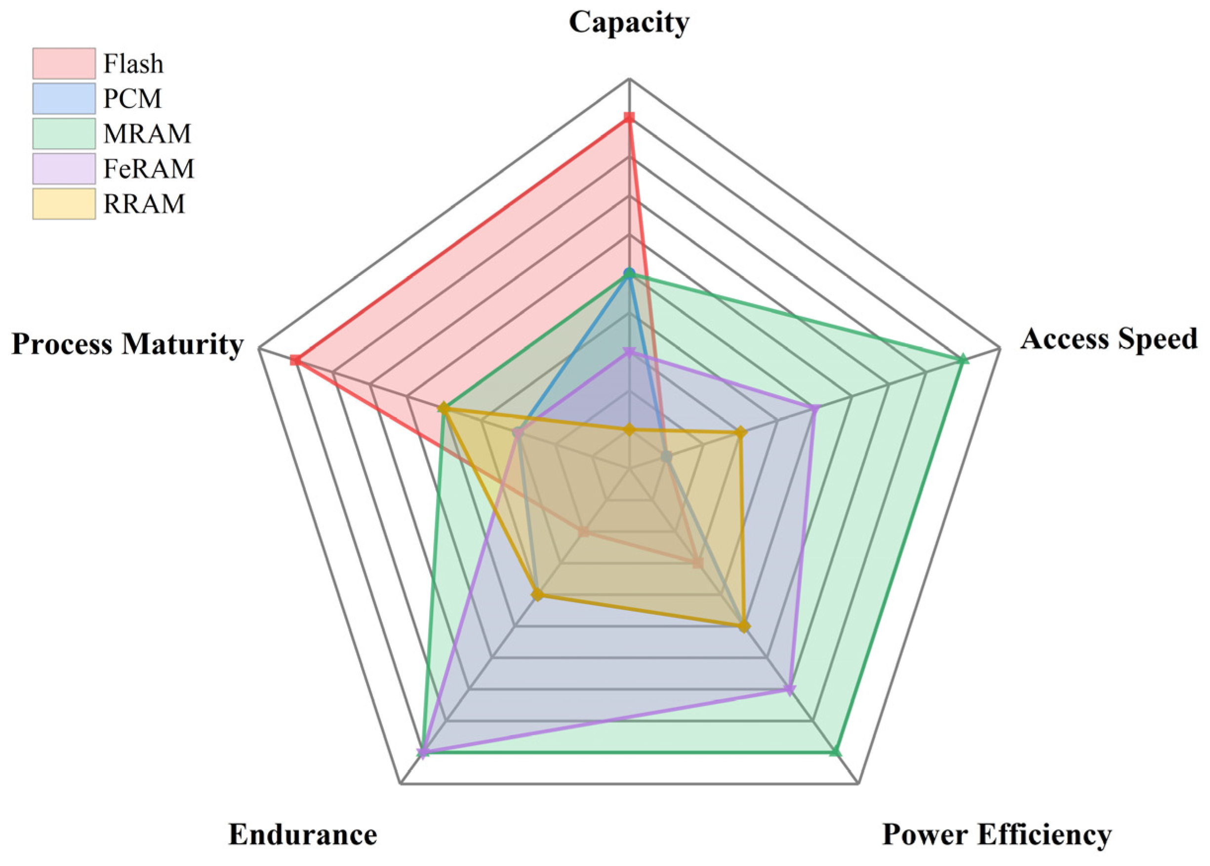
Leading semiconductor foundries and memory vendors are accelerating the commercialization of emerging resistive-type non-volatile memory technologies across advanced technology nodes. For example, TSMC currently offers RRAM up to 22 nm nodes [66] and the spin-transfer torque magnetic RAM (STT-MRAM) up to 16 nm nodes [66]. STMicroelectronics provides phase-change memory at the 28 nm node [123]. Ferroelectric device technology has also attracted much attention from the major foundry players such as GlobalFoundries, Sony, and Micron [124,125]. In particular, Micron and Sony are collaborating to develop ferroelectric RAM based on HfO2 material shows superior characteristics that almost meet DRAM specifications while providing certain nonvolatility [125]. Remarkably, their prototype chip density has progressed from 32 Gb in recent years. These emerging NVMs typically demonstrate some sub-100 ns write/read speeds, over 106 endurance cycles. Noting that ultra-low write voltage of less than 1 V is also possible for MRAM, and FeFET excels in extremely low write energy (<10 fJ/bit) [125]. Table 1 produces a detailed comparison of various characteristics of NVM [43]. A qualitative comparison is shown in Figure 21. Most non-volatile memories (NVMs) exhibit acceptable endurance levels. For example, MRAM/FeRAM offer very high endurance (>1015 cycles), nearing SRAM/DRAM levels, making them ideal for frequent write operations in caches and main memory. PCM and ReRAM typically range from ~106 to 1012 cycles, significantly better than NAND Flash but substantially lower than volatile memories or MRAM/FeRAM. NAND Flash usually suffers from the lowest endurance (SLC: ~106 cycles, TLC/QLC: ~103 cycles) due to oxide degradation during program/erase. It requires sophisticated wear leveling, error correction (ECC), and over-provisioning, limiting write-intensive applications. In terms of storage capacity, SRAM has the lowest density among these technologies due to its 6–10T cell structure, confining it to small, high-speed caches. DRAM faces significant scaling challenges due to capacitor leakage and complex cell structures, limiting density growth compared to NAND or advanced NVMs. Primarily used for main memory, where capacity is secondary to speed. Among NVM, NAND Flash stands out with the highest commercially available capacity, orders of magnitude greater than other types of NVM. This exceptionally large capacity highlights its technological maturity, particularly in terms of mass production processes and CMOS process compatibility. However, the access speed of NAND Flash remains the poorest among the listed NVM options, with a latency of around 100 nanoseconds. NVM is generally faster than NAND Flash but slower than DRAM (latency ~10 ns, high speed and bandwidth, suitable for main memory), and significantly slower than SRAM (latency ~1 ns, used for CPU cache). High speed comes at the cost of density and static power. From the perspective of energy efficiency comparison, NVM offers significant advantages for idle power (zero static power due to non-volatility). The “Write” energy of MRAM/FeRAM is very low, while PCM/ReRAM is moderate but generally lower than NAND Flash for small writes. SRAM has low dynamic read power but high static power consumption (leakage) due to the large number of transistors, especially at advanced nodes. However, DRAM has high dynamic power during access and significant static power consumption due to constant refresh, a major system energy drain. NAND Flash also has high energy consumption per program/erase operation due to high voltages required for Fowler–Nordheim tunneling or hot carrier injection. Read energy is relatively low. Block-based writes cause write amplification. As a result, except for certain embedded IoT systems, NAND Flash is not suitable as a primary memory replacement for general-purpose or high-performance computing applications, where SRAM or DRAM typically dominate.
For such applications, magneto-resistive RAM, especially Spin-Orbit Torque MRAM (SOT-MRAM), presents a more promising alternative. It offers nanosecond-level latency and exceptional energy efficiency, consuming only a few femtojoules per bit, and has much longer endurance. Despite its advantages, MRAM technology is still less mature compared to NAND Flash, particularly regarding capacity and CMOS process compatibility. Until MRAM is ready for widespread general-purpose, high-capacity in-memory computing, Ferroelectric RAM may serve as a viable transitional technology in this domain.

3. Memory Technology for More Moore in Computing

The advancement of memory technology plays a pivotal dual role in modern computing. On one hand, it extends the trajectory of Moore’s Law beyond the limits of device scaling. On the other hand, it forms a critical foundation for big data processing, especially for artificial intelligence (AI) applications, which are inherently data intensive. Although various types of memory exist, none are ideal in isolation. Current computer architectures rely on a carefully engineered trade-off, leveraging the strengths of different memory technologies. SRAM (Static Random-Access Memory) stores data using bistable flip-flops, offering ultra-high-speed performance. However, its need for at least six transistors per bit results in high cost, substantial power consumption, and large cell size, limiting integration density. DRAM (Dynamic Random-Access Memory) utilizes a capacitor-transistor pair per bit. The capacitor stores charge representing data, while a MOS transistor controls access and read/write operations. DRAM achieves higher density and lower cost compared to SRAM. However, it suffers from longer access times due to capacitor charging/discharging, destructive read operations, and the need for periodic refresh cycles to maintain data integrity. DRAM has matured over the decades, and its technology serves as a key benchmark for silicon foundries. A recent milestone includes the development of high-bandwidth DRAM exceeding 1 Gbit/mm2, enabling powerful GPU applications [126].
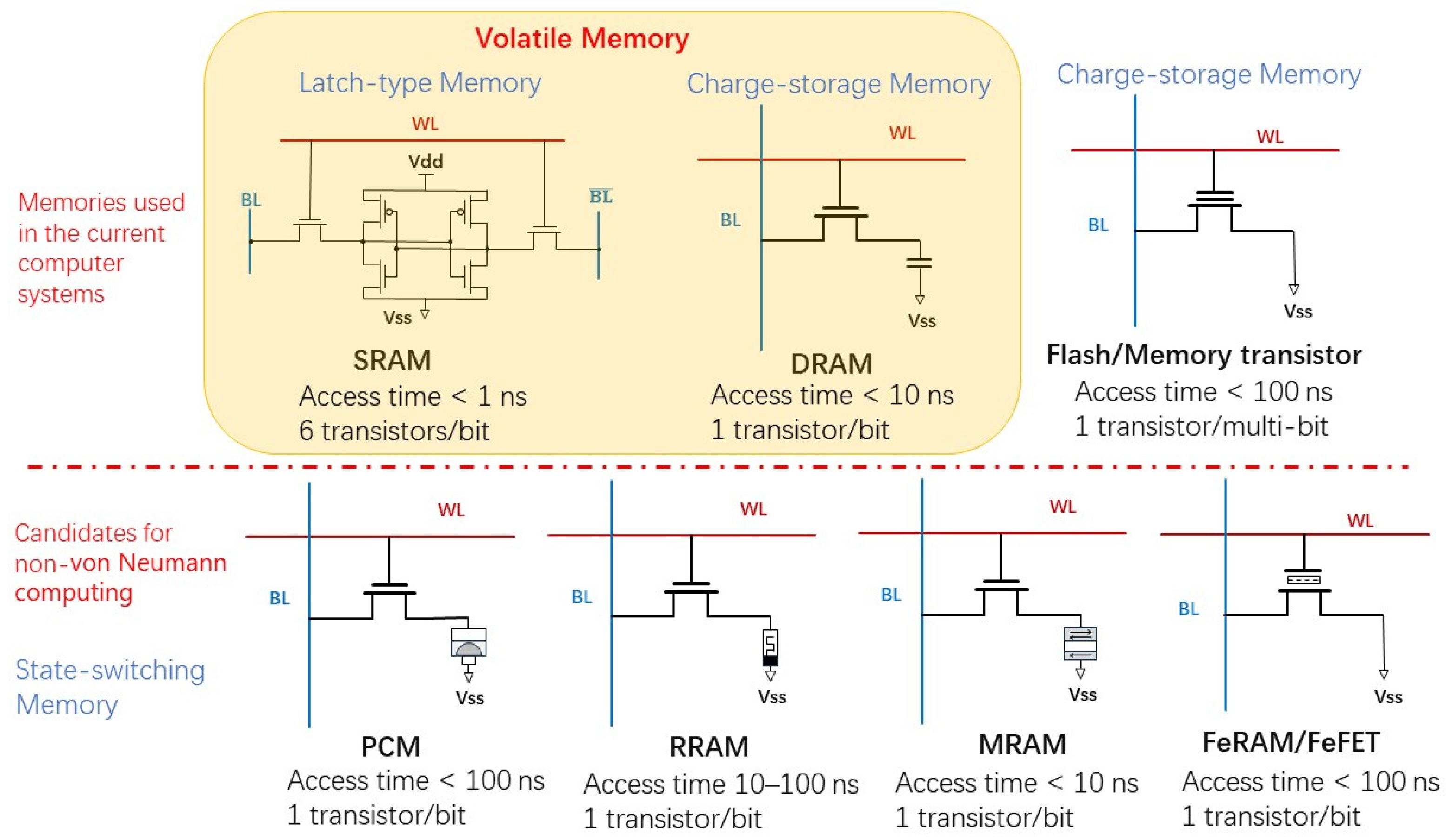
Despite their strengths, both SRAM and DRAM are volatile, necessitating non-volatile memory for data backup and mass storage. Flash memory serves this role effectively. Using a Floating Gate to trap charge, Flash provides data retention exceeding 10 years with minimal read power. Multi-level cell (MLC) storage is possible, and with 3D stacking technologies, Flash NAND has become the densest semiconductor memory, surpassing 400 layers and 28 Gbit/mm2 as of 2025 [54]. The primary drawback remains its relatively slow write speed compared to SRAM and DRAM. Figure 22 compares the device or circuit structures and their key characteristics of various memories used in or introduced to a computer system. The second row of Figure 22 illustrates the circuit configuration of key characteristics of these emerging NVM.
To bridge the gap between performance and data persistence, a new generation of non-volatile memory technologies has garnered significant attention [127]. These memory types offer inherent non-volatility, low power consumption, and high-speed access, making them ideal candidates for unified memory architectures in embedded systems and Internet of Things (IoT) applications. Moreover, due to their robustness against extreme environmental conditions, such as wide temperature ranges and radiation exposure, these memory technologies are particularly well suited for high-reliability domains like aerospace and automotive electronics. Notably, emerging non-volatile memory (NVM) technologies are instrumental in unlocking new computational models by enabling logic-in-memory functionalities and accelerating AI/ML workloads. By reducing data movement and increasing parallelism, NVMs offer transformative capabilities for handling complex tasks and combinatorial optimization problems [125,126,127,128,129]. In addition, NVMs are foundational to novel computing paradigms such as in-memory computing and neuromorphic architectures that emulate the processing behavior of biological neural networks. These approaches pave the way for energy-efficient, massively parallel systems, positioning emerging memory technologies as key enablers of the next generation of computing.

3.1. Missing Element and Ignored Logic Gate

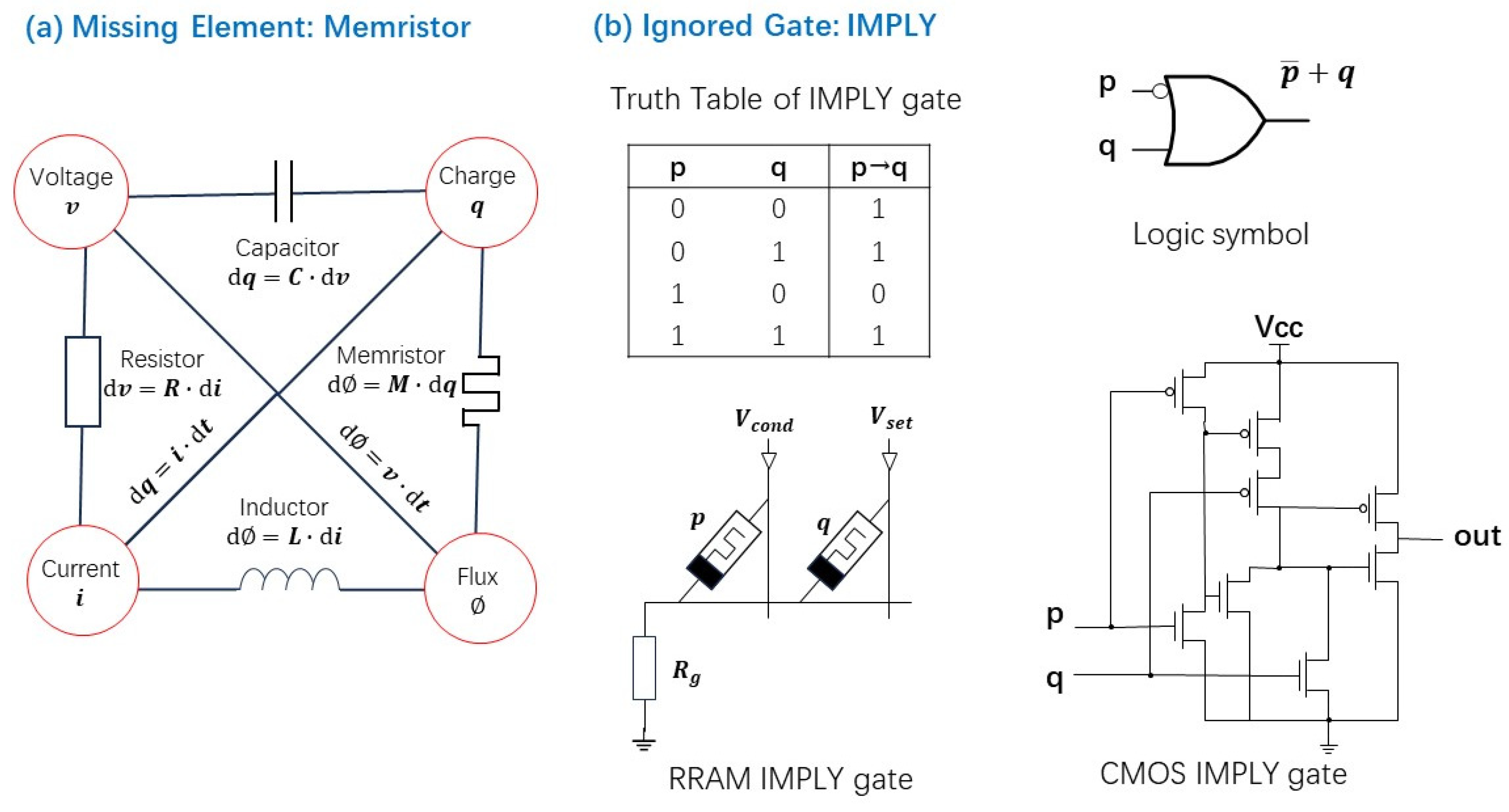
The memristor, short for memory resistor, is often described as the missing fourth fundamental circuit element [129,130,131] because it completes the theoretical symmetry among the basic passive electrical components: the resistor, capacitor, and inductor. While three of the four possible pairings of fundamental electrical quantities have physical implementations, the flux–charge relationship lacked a corresponding device. In 1971, Chua proposed the memristor to fill this gap, establishing it as the fourth fundamental element in circuit theory [130]. As discussed in Section 2, various physical implementations of memristors have since been proposed. Although their memory density currently remains below that of conventional solid-state memory, their non-volatility, low power consumption, and ultra-fast switching characteristics position them as highly promising candidates for future advancements in computing technology across multiple domains.
Memristors, with their unique ability to retain a memory, or with a characteristic function as charge to magnetic flux ratio, have opened up exciting possibilities in analog circuit design. Their nonlinear, history-dependent resistance makes them ideal for a range of analog applications where adaptability, compactness, and low power consumption. Memristors can act as tunable resistive elements, enabling the design of programmable gain amplifiers, filters, and oscillators [132]. Their resistance can be adjusted by applying specific voltage pulses, allowing for real-time reconfiguration without mechanical switches or digital control logic. Due to their inherent nonlinearity, memristors are used in generating chaotic signals for secure communications and random number generation. On the other hand, analog memristor circuits are central to neuromorphic computing, where they emulate synaptic weights in artificial neural networks. This will be discussed in Section 3.3.4.
In the theoretical extension of symbolic logic as introduced in “The Laws of Thought” by Boole in 1854 [133], operations such as NOT, OR, and AND laid the foundation for modern logic systems. In addition to these, two other logical operations—IMPLY and EQUIVALENT— were also important in Boolean logic. These functions reflect conditional statements akin to those used in contemporary programming languages.
The foundation of contemporary digital electronics was laid by Shannon [134], who applied Boolean logic to analyze the complex electrical networks via relay switching—a key early realization of hardware-based electrical logic circuits. However, in Shannon’s relay systems analysis and realization, the IMPLY and EQUIVALENT operations were notably excluded. This exclusion continued as transistor-based digital circuits and early microprocessors were developed, potentially steering the direction of digital architecture away from certain logical constructs. Interestingly, this omission aligned—perhaps serendipitously—with the practical limitations of CMOS technology. Although the IMPLY function is logically equivalent to “NOT p OR q”, implementing it in CMOS typically requires around eight transistors (see Figure 23b), making it an inefficient choice for most digital designs.
The emergence of the memristor in recent years marks a pivotal shift. IMPLY logic can be implemented using just two memristors [135]—a far simpler solution than traditional CMOS-based NOR or NAND gates. Figure 23 depicts the schematic of a memristor-based IMPLY gate. CMOS IMPLY gate configuration is also shown for comparison. For the memristor scheme, the two memristors represent logical operands p and q. Their logic states are encoded by resistance levels: High-Resistance State (HRS) corresponds to logic 0, and Low-Resistance State (LRS) corresponds to logic 1. The switching behavior of these devices is governed by two voltage thresholds: Vcond, the minimum voltage required to initiate state change, and Vset, the voltage necessary to fully switch a memristor from HRS to LRS.
The IMPLY operation is realized as follows:
-
If p is in HRS (logic 0), no current flows, and q’s state remains unchanged. The output is thus equal to q.
-
If p is in LRS (logic 1) and q is in HRS (logic 0), current flows through the circuit, switching q to LRS. The output becomes logic 1.
-
If both p and q are in LRS, current flows, so q remains unchanged at logic 1.
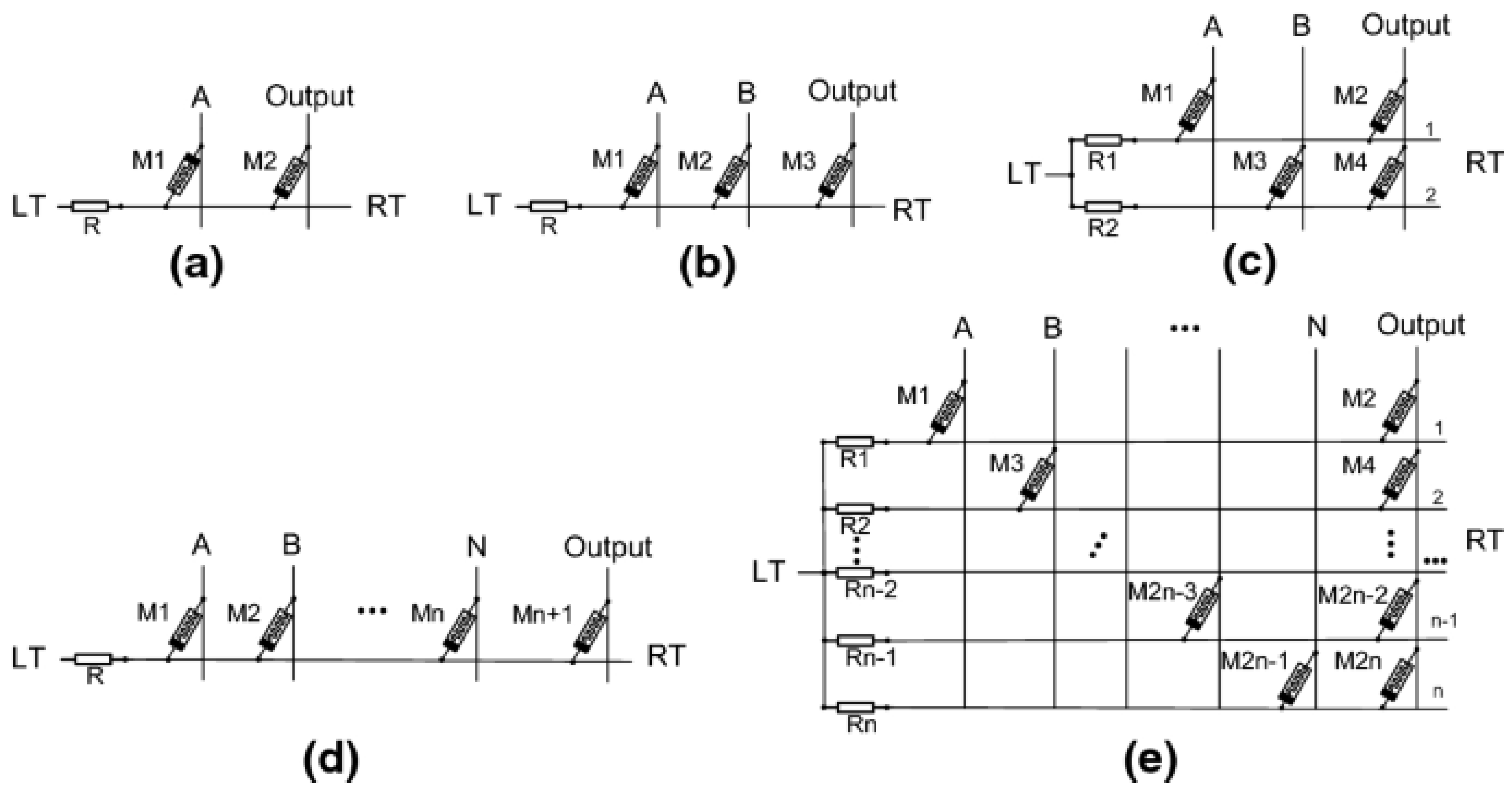
These behaviors conform to the truth table of the logical implication operation, demonstrating how memristors can natively perform fundamental logic using minimal hardware. Noting that other standard logic functions can also be implemented with IMPLY gates. Figure 24 shows the design of NOT gate, AND, and OR gates. In the next section, we shall demonstrate the design of a full adder, shift registers, and multipliers, using the memristor and IMPLY gates. In fact, almost all the emerging In-Memory Computing (IMC) systems (to be discussed in Section 3.3) are based on the memristive IMPLY gates. From a design standpoint, this enables logic circuits to be built with significantly fewer components, potentially transforming digital hardware architecture [136]. From the traditional CMOS circuit point of view, memristor-based logic suggests substantial performance improvements. The same component count can now deliver increased functionality and efficiency. Within the broader scope of Moore’s Law, memristor-based circuits offer a promising path toward continued progress, ushering in a new phase of “More Moore”.

3.2. Conventional Logic Block Built with Memristor

Memristor-based logic circuits are gaining traction as promising alternatives to traditional CMOS designs, particularly for arithmetic and sequential logic operations. In this section, we took full adders, shift registers, and multipliers as examples, which are the key functional building blocks for in-memory computing, to demonstrate the advantages of memristors in traditional logic circuit applications.

3.2.1. Full-Adder Design Using Memristors
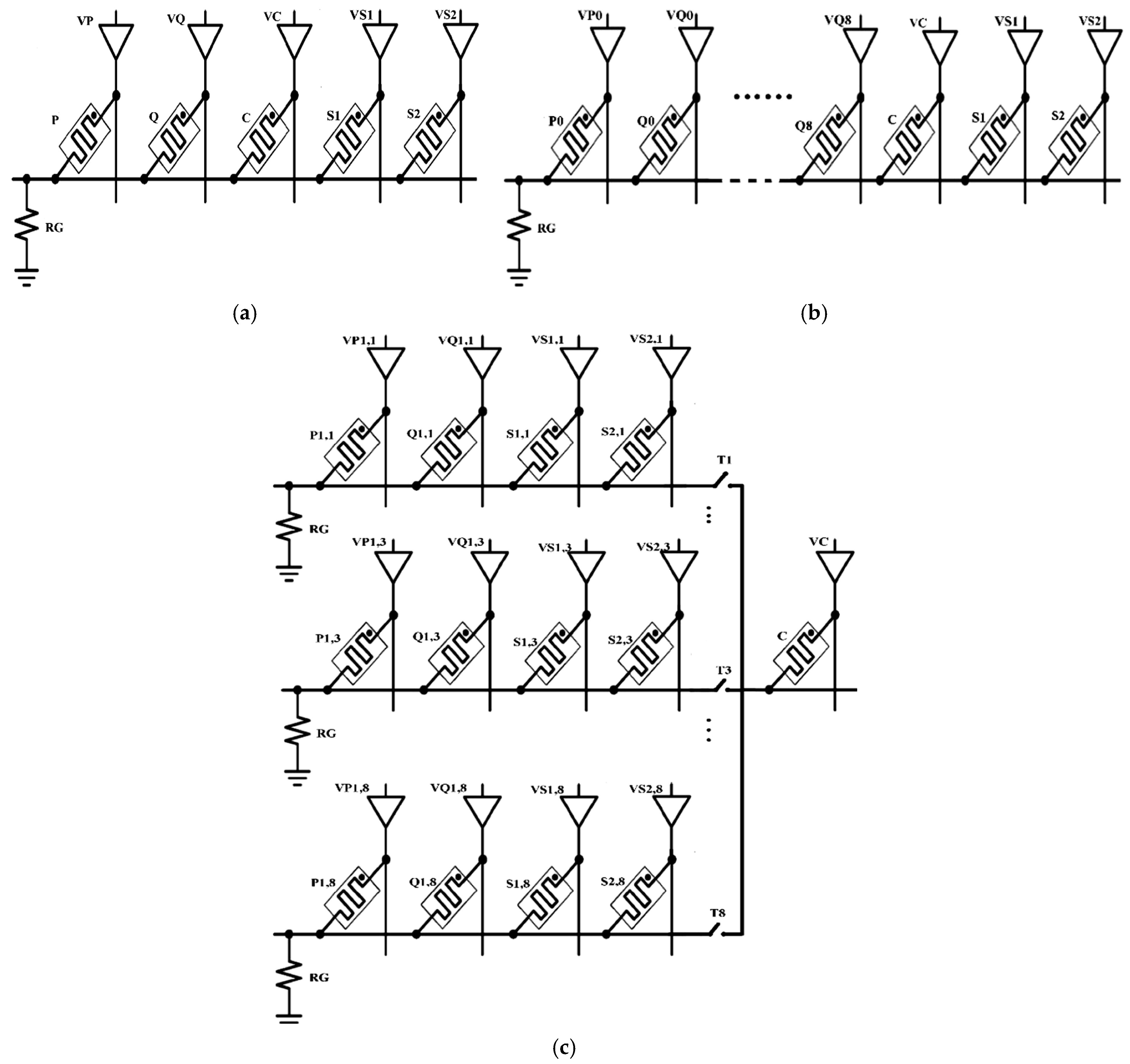
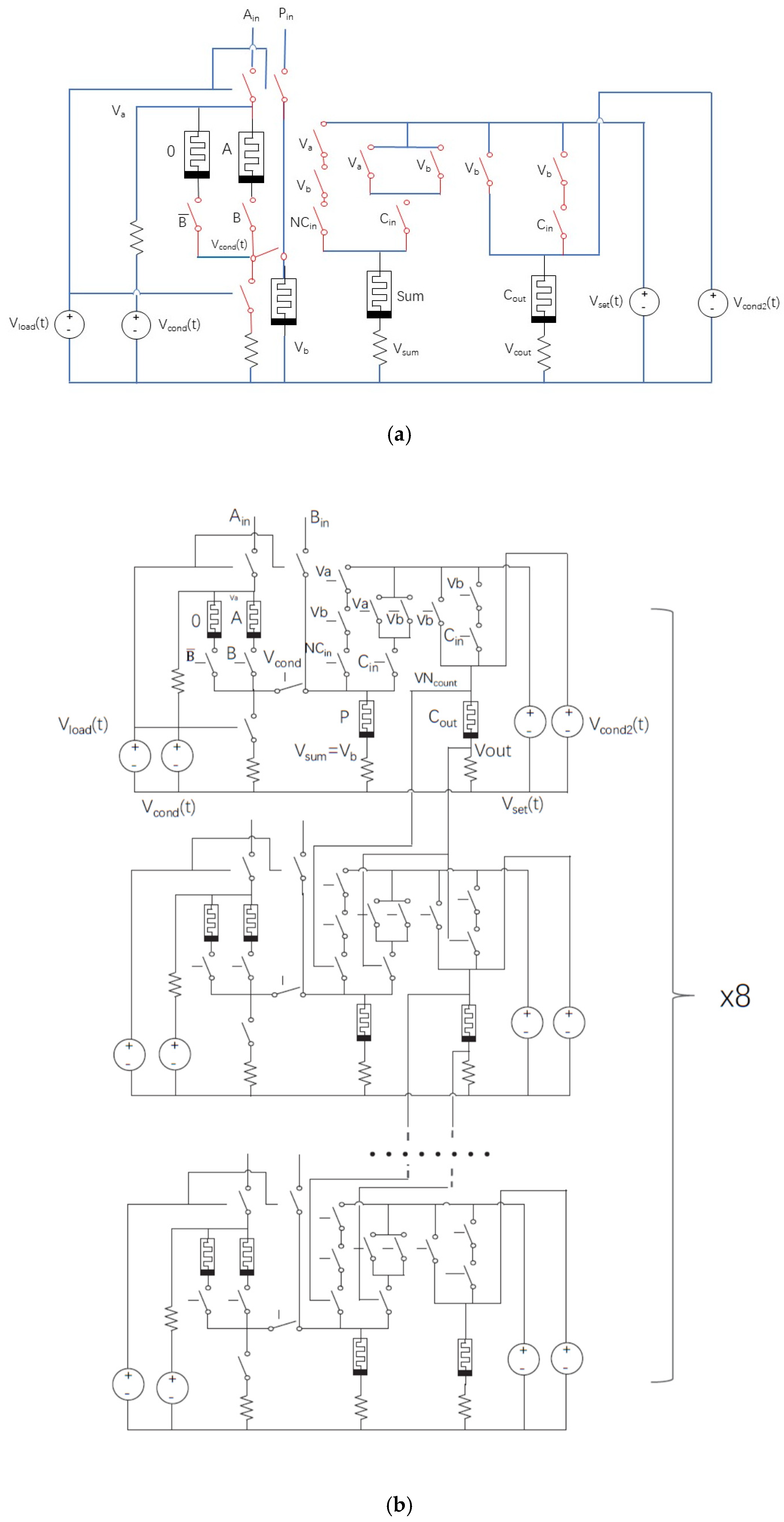
A full adder is a fundamental digital circuit that computes the sum of three binary inputs: P, Q, and Carry-in, C. In memristor-based implementations was based on IMPLY logic [137,138,139,140]. Figure 25a illustrates a one-bit full adder using IMPLY gates [138], featuring a memristor crossbar array coupled with IMPLY logic to execute the adder function. Here, P and Q are the binary numbers to be added, C is the carry-in, and the sum (including carry out) is accumulated via memristors S1 and S2. One of the key advantages of memristor-based full adders is their remarkable device efficiency. The number of memristors required for a 1-bit full adder can be reduced to just five, a significant improvement over the traditional CMOS-based designs. In contrast, a standard CMOS full adder typically uses 28 transistors [141], with optimized versions still requiring 17 transistors [142]. Multiple-bit full adder can be simply cascaded by a one-bit full adder in series (see Figure 25b).
Figure 24. Circuit schematic of (a) NOT gate, (b) two-input AND gate, (c) two-input OR gate, (d) multi-input AND gate, and (e) multi-input OR gate, realized with memristors [140]. © 2020 Springer Nature. Reproduced with permission.
Electronics 14 03456 g024
Figure 25. (a) Architecture of a one-bit full adder implemented using memristor-based IMPLY logic. (b) An 8-bit full adder constructed by serially cascading one-bit IMPLY-based adders. (c) An 8-bit parallel-serial full adder designed with memristive IMPLY logic [138]. © 2018 Springer Nature. Reproduced with permission.
Electronics 14 03456 g025
Thanks to their higher device density, simplified interconnects, and lower power consumption, memristor-based adders could be viewed as multiple generations ahead of CMOS technology, assuming comparable functional cell sizes can be achieved. Their non-volatile nature further enhances suitability for in-memory computing, allowing logic and memory operations to coexist within the same substrate. However, despite these advantages, memristor technology—particularly in the form of Resistive Random-Access Memory (RRAM)—still faces challenges. Issues such as limited endurance, device variability, and process immaturity currently prevent widespread adoption and consistent accuracy, especially when compared to the well-established and highly optimized CMOS counterparts.

3.2.2. Shift Register Design Using Memristors

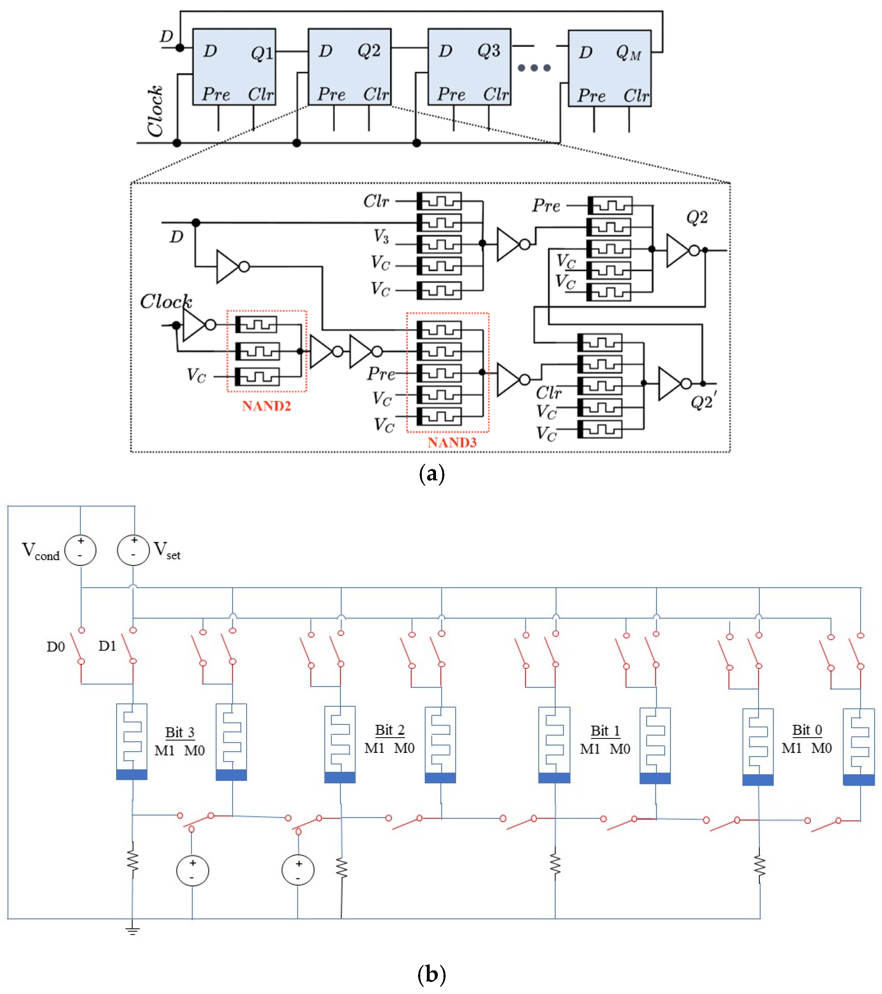
Shift registers are essential components for storing and transferring binary data sequentially across clock cycles. In memristor-based shift registers, information is encoded via stateful logic, wherein the memristor’s resistance state directly represents the binary bit value [143,144,145,146]. Figure 26 presents various architectures of memristor-based shift registers. In Figure 26a, a circular shift register configuration is shown, demonstrating the use of memristors in implementing conventional D-type flip-flops [144]. Here, the D-type flip-flops, as shown, are implemented with memristors. Figure 26b illustrates a four-bit shift register, each bit composed of two memristors (m0 and m1) in parallel. The circuit facilitates data transfer from a high bit to a lower bit, i.e., right shift, through Vcond and Vset pulses applied between adjacent devices [146].
A key advantage of these designs lies in their improved data retention, attributed to the non-volatile nature of memristors. Compared to traditional SRAM-based shift registers, memristor implementations offer significantly higher density and ultra-low standby power consumption. However, they currently face challenges such as lower switching speeds and potential long-term reliability concerns due to resistance drift and cumulative errors from frequent switching. Nevertheless, because of their compact footprint, energy efficiency, and intrinsic non-volatility, memristor-based shift registers hold strong promise for future in-memory computing architectures.

3.2.3. Multiplier Designs Using Memristors

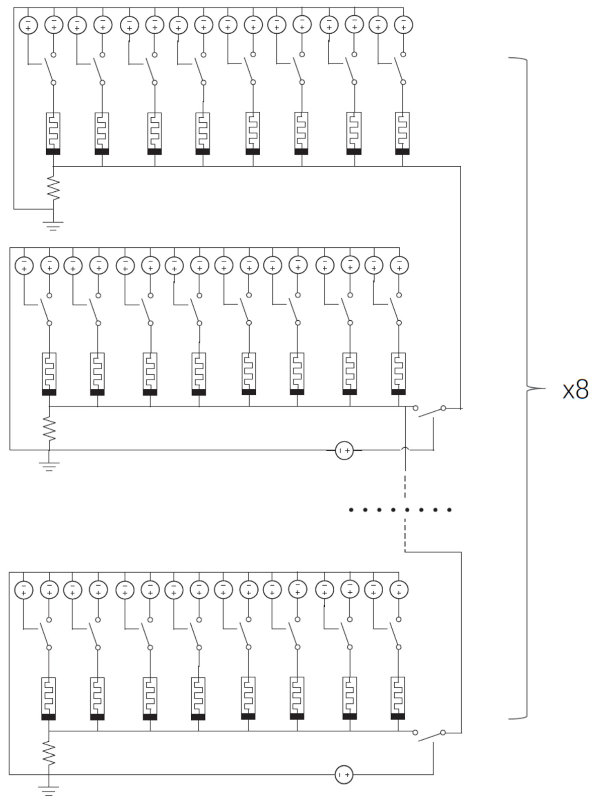
Multipliers play a pivotal role in digital signal processing and artificial intelligence workloads. Memristor-based multipliers often employ array architectures incorporating XNOR gates, full adders, and IMPLY logic [146,147]. Figure 27 and Figure 28 illustrate two optimized memristor-based multiplier designs [146], which have reduced area and latency. In the first design, it is a ripple carry multiplier that requires 24 clock cycles to complete an 8-bit multiplication. The second designs make use of CMOS logic or MAD (Memristor-Aided Logic) gates to enhance performance and efficiency. The use of memristor-based IMPLY logic enables compact adder implementation, resulting in high circuit density and low power consumption. According to Guckert and Swartzlander, by employing memristor IMPLY gates, the multiplication delay was reduced from 2N2 + 29N to 2N2 + 21N steps, while the component count decreased from 17N + 3 to 7N + 1 memristors for the first design. By adopting MAD logic, the multiplication can be completed in only N2 + N steps using just 5N memristors and 3N + 2 driver circuits. Separately, Sun et al. proposed a method to convert multiplication into multi-bit addition using Multiple Input Multiple Output (MIMO) logic, thereby enhancing execution speed and reducing system complexity (see Figure 29) [147].
Thanks to the nonvolatile nature of memristors, these designs minimize data movement, crucial for processing-in-memory architectures. Overall, memristor-based binary multipliers offer a reduction in the number of computation steps and achieve greater area efficiency, with spatial requirements falling to less than one-sixth of conventional CMOS counterparts. In addition, they demonstrate superior scalability and are well suited for future in-memory computing applications. However, current limitations primarily stem from the immature state of memristor technology. Process variations and device-level nonuniformities can affect the accuracy and reliability of multiplication operations.

3.3. Impact of Non-Volatile Memory Technology in Computing

3.3.1. Memory Replacement and NVM Augmenting to Von-Neuman Computer

In the traditional von Neumann architecture, memory and processing units are physically distinct, resulting in an inherent separation between computation and data storage. To balance trade-offs in speed, power consumption, cost, and capacity, modern computing systems organize memory hierarchically into three tiers: SRAM, DRAM, and Flash NAND.
The fastest level—cache and main memory—relies on high-speed SRAM, which stores one bit per cell using a six-transistor (6T) configuration [141]. While SRAM offers extremely low latency, it comes with significant drawbacks: high cost, large power dissipation, and limited storage density. For instance, in 3 nm technology nodes, the bit density of SRAM is approximately 30 Mbit/mm2 [148]. Further downsizing offers diminishing returns; the cell size is largely constrained by the interconnect overhead among transistors. For example, reducing from a 5 nm to a 3 nm node decreases the cell area by only ~5% (from 0.021 μm2 to 0.0199 μm2) [148].
Systems employ DRAM to achieve higher-capacity memory, storing one bit per transistor-capacitor pair. DRAM offers better density and lower cost than SRAM, but it has notable limitations: slower access times, destructive reads, and a requirement for periodic refresh cycles to preserve data integrity. Despite being the fastest available large-capacity memory, DRAM still lags significantly behind SRAM and processor speeds. Reportedly, memory access latency can be up to 100 times slower than internal processor access [149].
Because SRAM and DRAM are volatile, systems rely on non-volatile secondary storage—such as flash memory or solid-state drives (SSDs)—for persistent data and program storage. However, the energy and latency associated with data movement between memory and storage remain major bottlenecks. In mobile and energy-constrained systems, transferring data between DRAM and the processor can account for over 35% of total system energy consumption [150]. This is further exacerbated by the gap between DRAM and slower secondary storage technologies, both in terms of latency and energy efficiency.
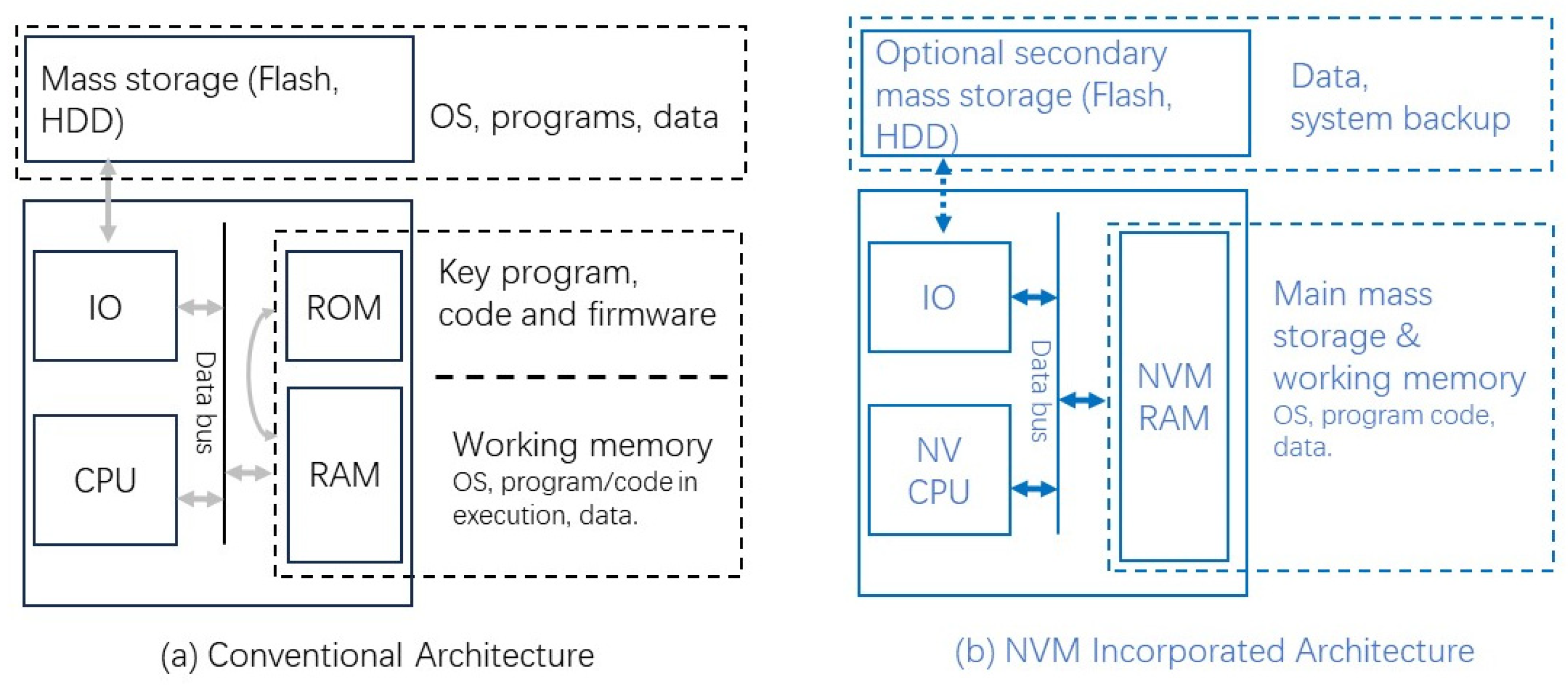
Emerging non-volatile memory (NVM) technologies have the potential to permeate nearly every layer of the traditional von Neumann computer architecture due to their advantages in non-volatility, low power consumption, high speed, and large storage capacity. A natural first step in the evolution toward NVM-based computing is the replacement of energy-intensive volatile memories such as SRAM and DRAM with non-volatile alternatives [151]. Figure 30 illustrates the concept of a board- or chip-level non-volatile architecture.
In conventional computing platforms—including embedded systems and smartphones—the architecture typically comprises a CPU, application-specific processing units, bus interconnects, and a memory hierarchy consisting of ROM, SRAM, and DRAM. Due to the volatile nature and limited capacity of SRAM and DRAM, operating systems, application software, and user data are stored in secondary storage devices such as flash memory and magnetic hard drives. While ROM is a form of non-volatile memory, it lacks the capability for in situ reprogramming or data writing and is generally limited to storing firmware or startup routines. During system initialization, code must be loaded from ROM into DRAM, and user data must be retrieved from secondary storage into DRAM via the I/O and data buses. This process introduces latency and energy overhead. Furthermore, maintaining program execution and data in DRAM requires a continuous power supply. Upon task completion or system shutdown, computational results and system state must be written back to non-volatile storage, adding further delay and power consumption. Replacing volatile memory with NVM at the main memory level could significantly streamline this process by enabling persistent, low-power data retention, thus paving the way for a more efficient and unified memory architecture.
When the speed of non-volatile memory (NVM) approaches that of dynamic RAM (DRAM), it becomes feasible to consolidate ROM, DRAM, and even SRAM into a unified, high-capacity NVM-based memory system, as illustrated in Figure 30b. This architectural shift effectively eliminates traditional data transfer delays between ROM and RAM, as well as overhead associated with loading from or writing back to mass storage through the data bus and I/O subsystems. The figure retains a secondary mass storage unit, which can be made optional or removable depending on the application requirements. This configuration significantly reduces bus-related energy consumption and enables instant-on/instant-off functionality for system boot-up and shutdown, thereby reducing latency and the risk of data loss. Such a system is particularly well suited for always-on platforms, including smartphones, tablets, smart home devices, and IoT systems. For deep data processing, NVM integration can offer new and better computer architectures, reducing data transmission latency and bottlenecks. For instance, in AI training, the traditional mode requires the CPU to repeatedly schedule data from SSD to DRAM to GPU, resulting in data transfer consuming the majority of the time. In response to this, Samsung has developed the Z-NAND technology, which adopts a new solid-state storage layer between traditional DRAM and SSD. It has stronger performance than NAND flash and the non-volatile feature of DRAM. Meanwhile, technological innovation allows the GPU to directly access storage for data reading and writing, achieving sub-microsecond latency, which can be up to 16 times faster than traditional SSDs and reduces overall power consumption by 80%. Additionally, based on the high integrability of NVM, Sandisk has recently launched an ultra-large-scale (256 TB) SSD for AI data centers. They have restructured the storage architecture through technologies such as Direct Write QLC, BiCS8 2-Tb QLC die, and Ultra QLC power optimization.) By minimizing the need for standby power, this architecture contributes to substantial energy efficiency gains, and through innovations at the architectural level of data computing and storage, it will make an attractive candidate for next-generation computing environments.
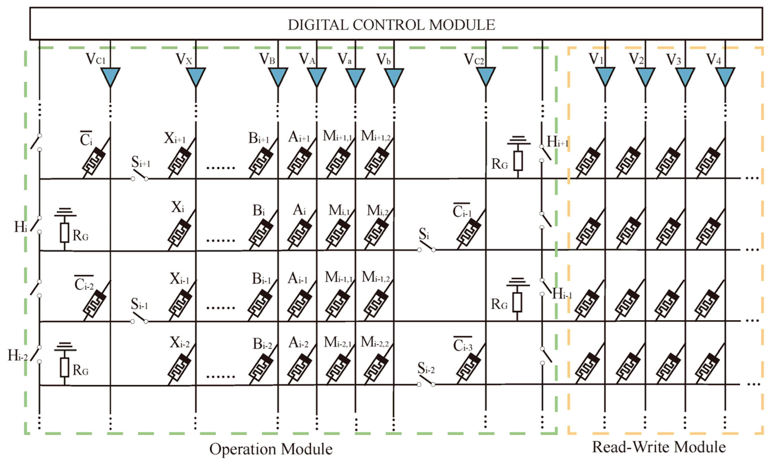
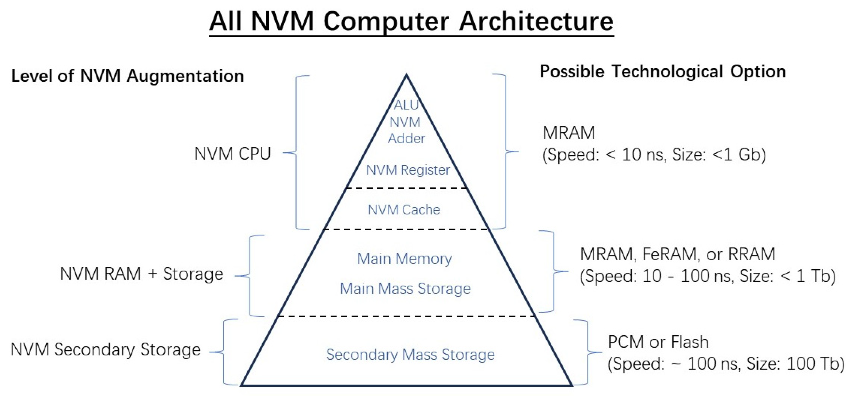
A more aggressive non-volatile memory (NVM) replacement scheme is illustrated in Figure 31. In this architecture, not only is the main memory replaced by NVM, but the internal storage and logic elements of the CPU—including registers, cache, and even logic functions—are reimagined using non-volatile look-up tables (LUTs) or crossbar-based structures. In fact, implementing the logic function using table lookups for pre-stored data in memory has been the fundamental configuration of existing graphics processing units (GPUs), which is also known as Computing-With-Memory (CWM). In the CWM scheme with GPU, highly efficient predefined basic operations in the GPU lack flexibility for general-purpose computing. However, a mixed mode and possibly a more innovative way of CWM could be possible for the von Neumann computer.
Given the performance characteristics of various memory components in contemporary computing systems, corresponding NVM technologies can be matched to achieve efficient replacements. For instance, MRAM offers the speed and endurance suitable for substituting CPU registers and cache. Meanwhile, the main memory could be cost-effectively implemented using RRAM, which balances performance and scalability. Although NAND flash remains the dominant choice for secondary storage—due to its maturity, low cost, and high density—RRAM presents a promising alternative. If advancements in RRAM fabrication can match the pace of NAND flash development, it could emerge as a viable candidate for general-purpose data storage in the future.

3.3.2. Near Memory Computing

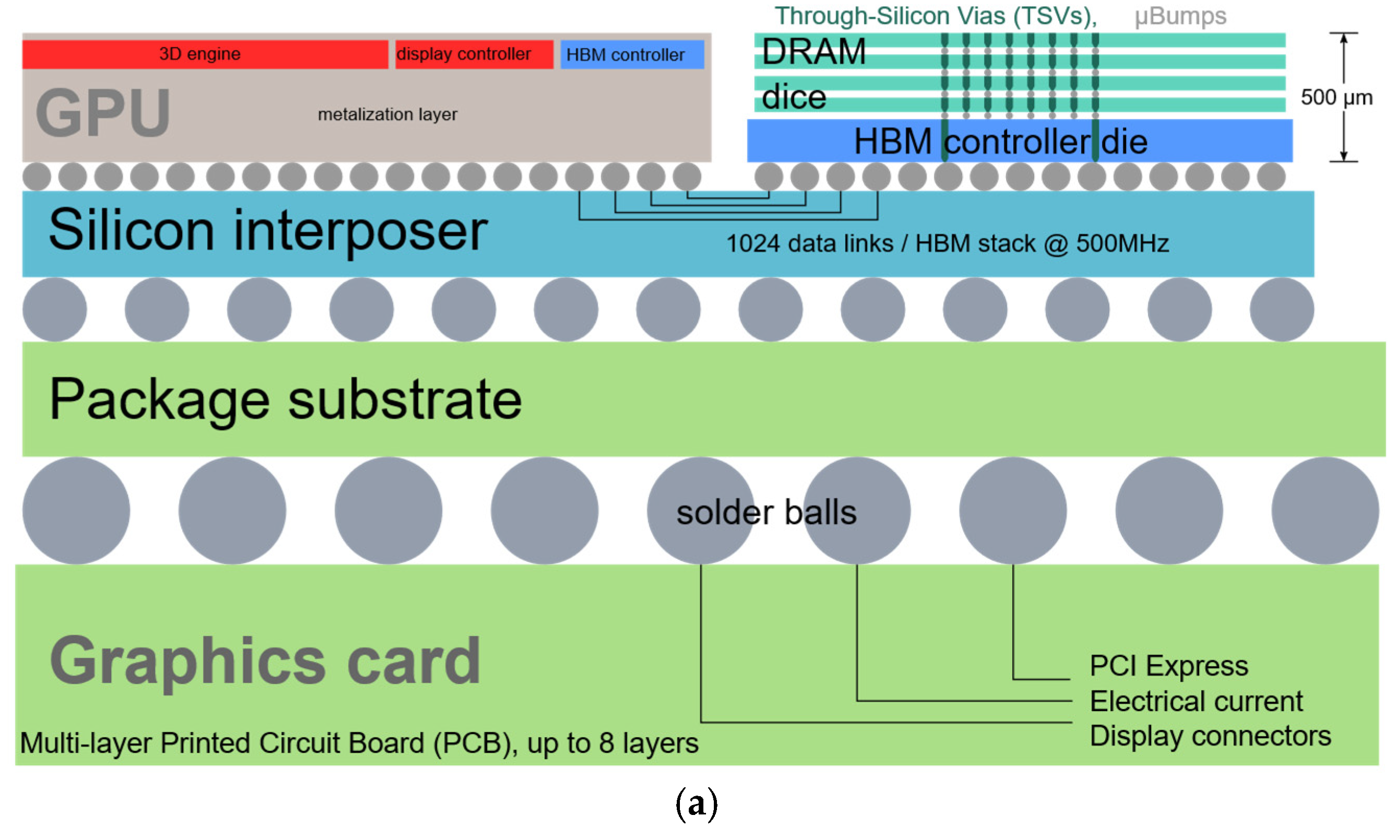
Further evolution of the NVM augmented von-Neumann computer is the near-memory computing (NMC) architecture. NMC addresses the persistent data movement bottlenecks inherent in conventional architectures by reorganizing memory structures and redefining the interface between memory and processing units [152,153,154]. In this paradigm, computations are executed on independent processing modules positioned close to—but external from—the memory arrays. Graphics Processing Units (GPUs) exemplify this architectural approach (see Figure 32a, for example).
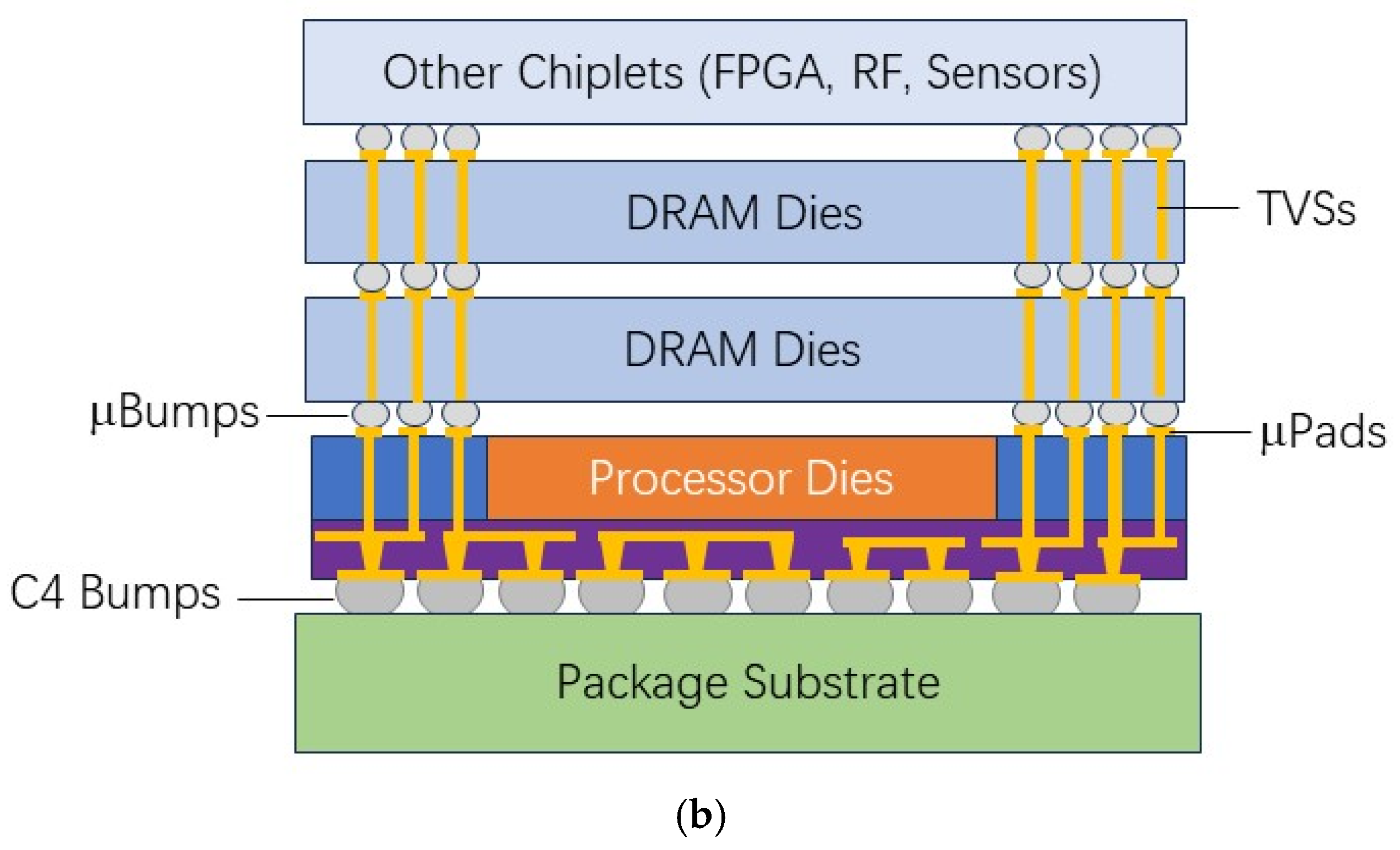
For general-purpose computing, near-memory computing (NMC) systems may still resemble conventional CPU–memory configurations (see Figure 32b). A prominent example is AMD’s Zen series CPUs, which adopt NMC principles through 2.5D packaging techniques that integrate multiple chiplets, particularly by placing high-bandwidth memory (HBM) alongside processor cores. This close integration reduces data latency, enhances communication bandwidth, and improves overall system performance by minimizing the distance between memory and compute elements [154]. As a result, NMC offers a cost-effective solution with manageable implementation complexity, positioning it as a compelling intermediate stage on the path toward fully in-memory computing.

3.3.3. In-Memory Computing (IMC)

The ultimate evolution of computing architecture is embodied by in-memory computing (IMC), also called logic-in-memory [38,155,156,157,158]. In this paradigm, logic operations are performed directly within the memory arrays, utilizing embedded digital or analog computing elements. This unified approach to computation and storage eliminates the need for frequent data transfers between separate processing and memory units, thereby streamlining data flow. A specialized form of IMC—neuromorphic computing, which emphasizes analog computation through convolutional neural networks for biologically inspired applications—also falls under this category and will be discussed in Section 3.3.4. The intrinsic parallelism of IMC enables highly efficient data processing across the memory fabric, significantly reducing data movement and power consumption. A notable implementation of this architecture was demonstrated by Xue et al., who designed a 4 Mb ReRAM-based IMC macro with 8-bit precision tailored for AI edge applications. Their design achieved an energy efficiency ranging from 11.91 to 195.7 TOPS/W, depending on operating conditions [66].
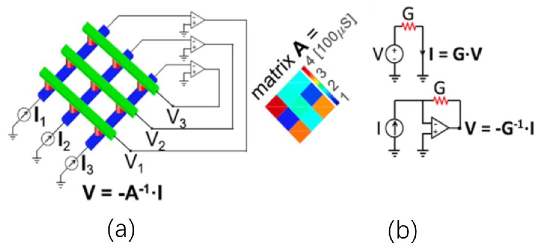
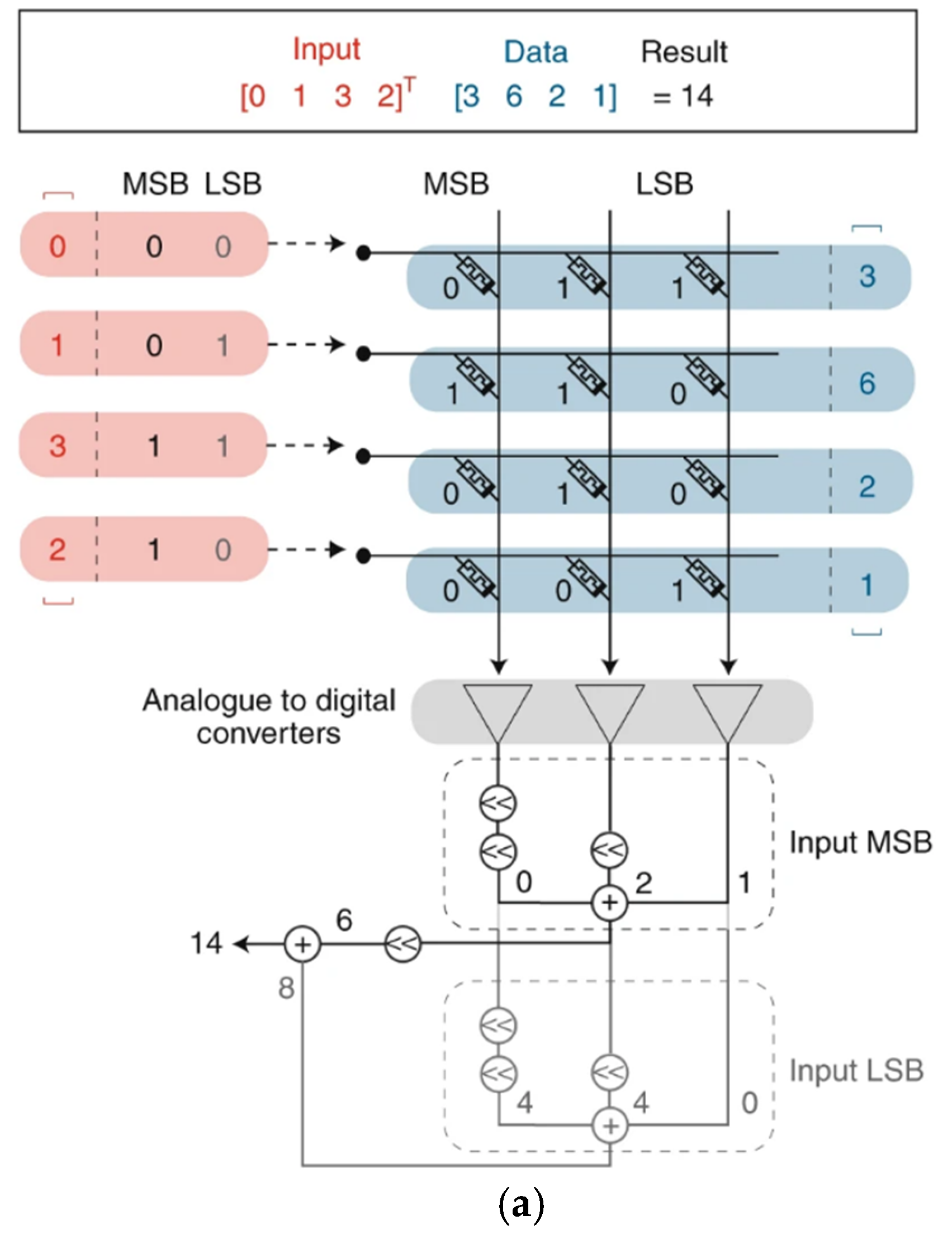
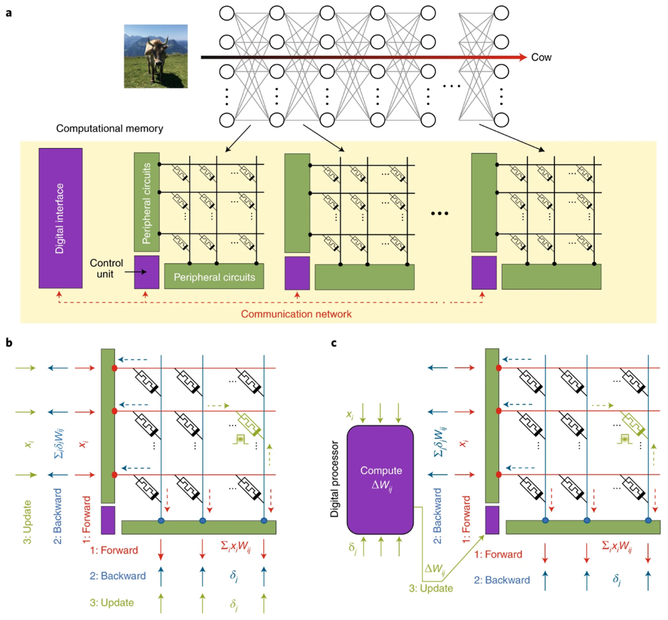
To illustrate the efficiency of non-volatile memory (NVM)-based in-memory computing (IMC) architectures, Figure 33 presents a Resistive Random-Access Memory (RRAM) cross-point array (represented as red cylinders positioned at the intersections of blue and green bars). This structure can solve a 3 × 3 linear system of the form I = GV, or its inverse form V = −G−1I [27]. In this configuration, the conductance values at each cross-point correspond to the respective elements of matrix A. Utilizing Ohm’s Law, the current vector I can be computed as the scalar product I = GV, where the input voltage vector V is applied across the word lines. Conversely, to retrieve the voltage vector V from known currents I, a transimpedance amplifier can be employed to perform scalar division, effectively realizing the matrix inversion operation in analog hardware. Crossbar-based memristor arrays offer scalability for both machine learning and scientific computing tasks. However, current Resistive Random-Access Memory (RRAM) technologies remain in an early stage of development and suffer from substantial inter- and intra-device variability. As a result, the precision of analog matrix-vector multiplication (MVM) operations is often insufficient for applications requiring high numerical accuracy, though it may still be acceptable for certain AI workloads. To address this limitation, Sebastian et al. proposed decomposing multi-bit vectors into 1-bit slices, distributed across separate crossbar columns (see Figure 34). As shown in Figure 34a, input bits are applied sequentially, with each resulting partial product undergoing analog-to-digital conversion and appropriate bit shifting prior to accumulation. The final inner product is then derived by summing all partial results. In addition, a mixed-precision computing strategy can be employed (see Figure 34b), where the outputs of low-precision analog MVM operations are iteratively refined. This approach improves the solution accuracy for systems of linear equations, thereby enhancing the feasibility of analog in-memory computing in data-intensive and numerically demanding applications [157].

3.3.4. Neuromorphic Computing

Extending beyond near-memory computing (NMC) and in-memory computing (IMC), neuromorphic computing seeks to emulate the efficiency, adaptability, and event-driven nature of biological neural systems. This paradigm leverages emerging non-volatile memory technologies—such as resistive RAM (RRAM) and phase-change memory (PCM)—to enable ultra-efficient pattern recognition and sensory information processing [159,160,161,162].
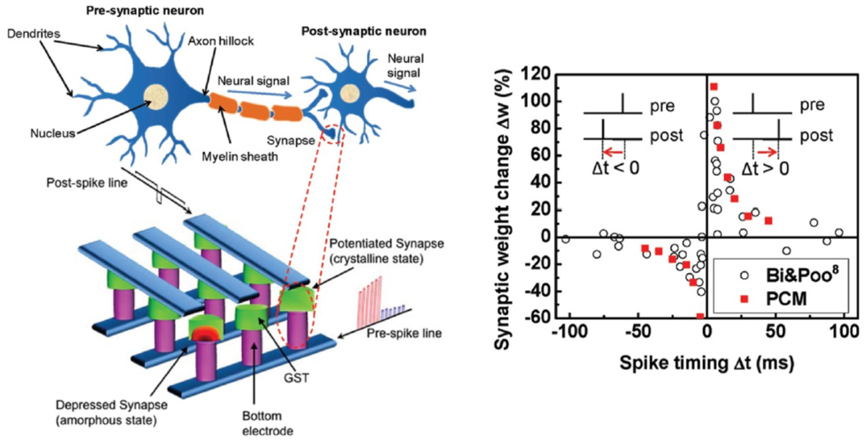
Neuromorphic hardware mimics synaptic behavior by utilizing memristive and other programmable-resistance devices, allowing for inherently parallel and asynchronous computation. These properties make it particularly well suited for edge AI applications. Ongoing research is directed toward developing scalable neuromorphic platforms built with a diverse array of non-traditional memory elements, including memristors, PCM, and related technologies. A comprehensive review on this topic has been given by Kudithipudi et al. [159]. The architectural principles, hardware–software co-design, and broader ecosystem requirements necessary for realizing large-scale neuromorphic systems were explored. The review highlights various applications, with a strong emphasis on low-power AI, real-time sensory processing, and on-device edge computing. Figure 35. Demonstration of a biological neuron emulation using a phase-change memory (PCM) array. The bioinspired interconnection scheme places PCM synapses between post-synaptic and pre-synaptic electrodes, enabling synaptic weight modulation based on the relative timing of neuronal spikes. This mechanism—implemented through PCM cells—faithfully reproduces spike-timing-dependent plasticity (STDP). The experimental results exhibit strong agreement with corresponding biological synapse data [161].
Recent advancements in deep artificial neural networks (DNNs), though only loosely inspired by biological cognition, have demonstrated human-level performance in tasks such as image and speech recognition [159,160,161,162,163]. The crossbar architecture of RRAM is particularly well suited for mapping DNNs, as it naturally supports parallel, analog in-memory computation. In this structure, synaptic weights are encoded as conductance values at the cross-points, with input signals applied as voltages across the wordlines. The corresponding output currents, read from the bitlines, represent the result of analog matrix–vector multiplication (MVM). Figure 36 depicts the implementation of a feedforward DNN using multiple crossbar arrays of memory devices [157]. Synaptic weights Wij are represented as conductance or charge states within the memory cells. Each layer of the network corresponds to a distinct crossbar. During forward propagation, input data are applied to the rows (wordlines), and outputs are extracted from the columns (bitlines). These outputs are passed through peripheral nonlinear activation circuits and fed into the next layer via a global communication network. Figure 36b,c illustrate two strategies for training neural networks using crossbar arrays. In Figure 36b, forward and backward propagations are performed by applying activation values xi and error signals δj to the rows and columns, respectively. Simultaneous row/column pulse application enables in-place weight updates via an approximate outer-product operation that directly programs the memory devices. In Figure 36c, the weight update ΔWij is calculated digitally and applied to the array through targeted programming pulses—offering greater precision and flexibility [157].
NVM technologies, particularly RRAM and PCM, have achieved significant milestones in neuromorphic computing. Neuromorphic hardware leverages NVM technologies—notably RRAM and PCM to directly emulate synaptic plasticity, enabling energy-efficient, parallel, and event-driven computation. These devices intrinsically mimic biological synapses: conductance states encode synaptic weights, while electrical pulses induce weight updates via nanoscale physical phenomena (e.g., ion migration in RRAM, amorphous–crystalline phase transitions in PCM). As depicted in Figure 35, PCM arrays implement bio-realistic STDP. Pre- and post-synaptic spikes generate voltage pulses across PCM cells, dynamically modulating conductance (synaptic weight) based on temporal correlation. This in situ learning mechanism avoids von Neumann bottlenecks by co-locating memory and computation. Similarly, RRAM crossbars (Figure 36) execute analog MVM—core to DNNs—by applying input voltages along wordlines and summing currents bitline-wise, with synaptic weights encoded as conductance states. This enables >10 TOPS/W energy efficiency (vs. <1 TOPS/W for GPUs), critical for edge AI.
Despite these successes, fundamental challenges impede commercialization. Device variability (>5% cycle-to-cycle/device-to-device conductance drift) degrades computational accuracy in analog matrix operations. Limited endurance (≤106 weight updates for RRAM/PCM vs. 1015 in biological synapses) constrains lifelong learning capabilities. System integration bottlenecks arise from peripheral circuitry (ADCs, drivers), which dominate area/power budgets, while sparse event-driven architectures require specialized NVM interfaces. Crucially, algorithm-hardware co-design gaps persist in mapping bio-inspired learning rules to NVM physics, limiting functional flexibility. Research now prioritizes novel material stacks and 3D integration to address density and variability. Hybrid precision architectures combining NVM (coarse weights) with CMOS (fine-grained tuning) aim to balance efficiency and accuracy. Concurrently, event-driven sparse computing paradigms and NVM-optimized neuromorphic compilers are being co-developed to overcome integration overheads. These pathways collectively target commercially viable neuromorphic edge systems capable of adaptive, ultra-low-power cognition.
In summary, neuromorphic hardware emulates synaptic behavior by employing memristors and other programmable-resistance devices, enabling inherently parallel and asynchronous processing. These characteristics make it particularly well suited for edge AI applications. Ongoing research is focused on developing scalable neuromorphic platforms using emerging non-volatile memory (NVM) technologies such as memristors, phase-change memory (PCM), and other non-traditional elements. Empowered by NVM technologies, many neuromorphic chips exhibit both low dynamic power consumption and minimal standby power, making them ideal for low-power, real-time processing in domains such as wearable electronics, robotics, and the Internet of Things (IoT). Despite promising advances, key challenges remain. A major hurdle is hardware heterogeneity, as current designs require the complex co-integration of diverse technologies—including CMOS, memristors, and spintronic devices. Moreover, similar to traditional CMOS systems, interconnect bottlenecks—especially in large-scale crossbar array architectures—can restrict communication bandwidth, potentially limiting system scalability and performance.

4. Conclusions

As the era of traditional CMOS scaling draws to a close, sustaining the momentum of Moore’s Law demands a paradigm shift in computing system design that prioritizes architectural innovation, energy efficiency, and data-centric processing. Non-volatile memory (NVM) technologies stand at the forefront of this transformation, not merely as memory alternatives but as foundational enablers of next-generation computing platforms.
By embedding intelligence within main memory and minimizing costly data movement, NVM-based solutions such as resistive RAM, MRAM, and PCM are unlocking unprecedented opportunities across the computing stack. From logic-in-memory accelerators to neuromorphic edge processors, these devices blur the boundary between memory and logic, paving the way for more responsive, resilient, and power-conscious architectures. The continued integration of NVM into heterogeneous systems will be central to achieving both “More Moore,” which extends the computer performance through functionally enhanced logic and systems designed based on NVM, and “More than Moore,” which enables in-memory computing and neuromorphic architectures for performance enhancement beyond the conventional scaling trajectories based on physical CMOS device downsizing. With this connection, future research must focus on addressing integration challenges, optimizing memory–logic co-design, and developing cross-disciplinary frameworks that harness the full potential of NVM in AI, edge computing, and beyond. With these efforts, non-volatile memory technologies are poised to play a defining role in the next chapter of scalable, intelligent, and sustainable computing, and most importantly, opening up additional options for “more Moore” for the greatest microelectronic technology we have.

Author Contributions

H.W. developed the theories and wrote and reviewed the manuscript. W.L. developed the theories and wrote the manuscript. J.Z. developed the theories and wrote and reviewed the manuscript. W.B. developed the theories and wrote the article. L.W. developed the theories and wrote the article. J.L. provided funding support, developed concepts, and proofread the article. All authors have read and agreed to the published version of the manuscript.

Funding

This work is supported by project #9239120 of the City University of Hong Kong, Hong Kong SAR, China, which is funded by Hubei JFS Lab, Wuhan, China.

Data Availability Statement

No new data were created.

Conflicts of Interest

Author Weidong Li was employed by the company Yangtze Memory Technologies Co., Ltd. The remaining authors declare that the research was conducted in the absence of any commercial or financial relationships that could be construed as a potential conflict of interest.

References

  1. Moore, G.E. Cramming More Components onto Integrated Circuits. Electronics 1965, 38, 114–117. [Google Scholar] [CrossRef]
  2. Wong, H.; Zhang, J.; Liu, J. Quest for more Moore at the end of Device Downsizing. J. Circuits Syst. Comput. 2025, 34, 2441003. [Google Scholar] [CrossRef]
  3. Wong, H.; Iwai, H. On the Scaling of Subnanometer EOT Gate Dielectrics for Ultimate nano CMOS Technology. Microelectron. Eng. 2015, 138, 57–76. [Google Scholar] [CrossRef]
  4. Wong, H. On the CMOS Device Downsizing, More Moore, More than Moore, and More-than-Moore for More Moore. In Proceedings of the 2021 IEEE 32nd International Conference on Microelectronics (MIEL), Nis, Serbia, 12–14 September 2021; pp. 9–15. [Google Scholar]
  5. Wong, H.; Zhang, J.; Liu, J. Contacts at the Nanoscale and for Nanomaterials. Nanomaterials 2024, 14, 386. [Google Scholar] [CrossRef] [PubMed]
  6. Ye, P.D.; Ernst, T.; Khare, M.V. The Nanosheet Transistor Is the Next and Maybe Last Step in Moores-Law. IEEE Spectr. 2019, 30. Available online: https://spectrum.ieee.org/the-nanosheet-transistor-is-the-next-and-maybe-last-step-in-moores-law (accessed on 22 January 2024).
  7. Wong, H.; Kakushima, K. On the Vertically Stacked Gate-All-Around Nanosheet and Nanowire Transistor Scaling beyond the 5 nm Technology Node. Nanomaterials 2022, 12, 1739. [Google Scholar] [CrossRef]
  8. Dennard, R.H.; Gaensslen, F.; Yu, H.-N.; Rideout, L.; Bassous, E.; LeBlanc, A. Design of ion-implanted MOSFET’s with very small physical dimensions. IEEE J. Solid-State Circuits 1974, 9, 256–268. [Google Scholar] [CrossRef]
  9. Arden, W.; Brillouët, M.; Cogez, P.; Graef, M.; Huizing, B.; Mahnkopf, R. More-than-Moore White Paper; International Technology Roadmap for Semiconductors (ITRS). 2010. Available online: https://www.seas.upenn.edu/~ese5700/spring2015/IRC-ITRS-MtM-v2%203.pdf (accessed on 26 June 2025).
  10. Cheng, Y.; Deen, M.J.; Chen, C.H. MOSFET Modeling for RF IC Design. IEEE Trans. Electron Devices 2005, 52, 1286–1303. [Google Scholar] [CrossRef]
  11. Liou, J.J.; Schwierz, F. RF MOSFET: Recent Advances, Current Status and Future Trends. Solid-State Electron. 2003, 47, 1881–1895. [Google Scholar] [CrossRef]
  12. Siu, S.-L.; Wong, H.; Tam, W.-S.; Kakusima, K.; Iwai, H. Subthreshold Parameters of Radio-Frequency Multi-Finger Nanometer MOS Transistors. Microelectron. Reliab. 2009, 49, 387–391. [Google Scholar] [CrossRef]
  13. Li, B.; Gao, M.; Cai, X.; Gao, Y.; Xia, R. A 3.7-to-10 GHz Low Phase Noise Wideband LC-VCO Array in 55-nm CMOS Technology. Electronics 2022, 11, 1897. [Google Scholar] [CrossRef]
  14. Jeong, J.; Kim, S.K.; Kim, J.M.; Geum, D.-M.; Kim, D.H.; Kim, J.; Kim, S.H.; Park, J.; Lee, J.; Lee, S.; et al. Heterogeneous and Monolithic 3D Integration of III–V-Based Radio Frequency Devices on Si CMOS Circuits. ACS Nano 2022, 16, 9031–9040. [Google Scholar] [CrossRef]
  15. Minixhofer, R.; Feilchenfeld, N.; Knaipp, M.; Röhrer, G.; Park, J.M.; Zierak, M.; Eichenmair, H.; Levy, M.; Loeffler, B.; Hershberger, D.; et al. A 120V 180nm High Voltage CMOS Smart Power Technology for System-on-Chip Integration. In Proceedings of the 2010 IEEE International Symposium on Power Semiconductor Devices & ICs (ISPSD), Hiroshima, Japan, 6–10 June 2010; pp. 217–220. [Google Scholar]
  16. Bustillo, J.; Fife, K.; Merriman, B.; Rothberg, J. Development of the ion torrent CMOS chip for DNA sequencing. In Proceedings of the 2013 IEEE International Electron Devices Meeting, Washington, DC, USA, 9–11 December 2013; p. 6724584. [Google Scholar] [CrossRef]
  17. Zhao, X.; Yan, J. CMOS Integrated Circuits for Low-Power and High-Efficiency Applications. Electronics 2024, 13, 3600. [Google Scholar]
  18. STMicroelectronics Whitepaer: Benefits of Using ST’s Wide Bandgap Technology. Available online: https://www.st.com/content/st_com/en/premium-content/premium-content-white-paper-unique-properties-of-wide-bandgap-materials.html (accessed on 26 June 2025).
  19. Sheikhan, A.; Narayanan, E.M.S. Characteristics of a 1200 V Hybrid Power Switch Comprising a Si IGBT and a SiC MOSFET. Micromachines 2024, 15, 1337. [Google Scholar] [CrossRef] [PubMed]
  20. Bao, W.; Zhang, J.; Wong, H.; Liu, J.; Li, W. Emerging Copper-to-Copper Bonding Techniques: Enabling High-Density Interconnects for Heterogeneous Integration. Nanomaterials 2025, 15, 729. [Google Scholar] [CrossRef]
  21. Ren, C.; Zhang, Y.; Nadappuram, B.P.; Akpinar, B.; Klenerman, D.; Ivanov, A.P.; Edel, J.B. Integration of Graphene Field-Effect Transistors with CMOS Readout Circuits for Ultra-Sensitive Biosensing. ACS Appl. Electron. Mater. 2021, 3, 4418–4423. [Google Scholar] [CrossRef]
  22. Filipovic, L.; Selberherr, S. Application of Two-Dimensional Materials towards CMOS-Integrated Gas Sensors. Nanomaterials 2022, 12, 3651. [Google Scholar] [CrossRef] [PubMed]
  23. Wong, H.; Filip, V.; Wong, C.K.; Chung, P.S. Silicon Integrated Photonics Begins to Revolutionize. Microelectron. Reliab. 2007, 47, 1–10. [Google Scholar] [CrossRef]
  24. Wong, C.K.; Wong, H.; Chan, M.; Chow, Y.T.; Chan, H.P. Silicon Oxy-Nitride Integrated Waveguide for On-Chip Optical Interconnects Applications. Microelectron. Reliab. 2008, 48, 212–218. [Google Scholar] [CrossRef]
  25. Wong, C.K.; Wong, H.; Kok, C.W.; Chan, M. Silicon Oxynitride Prepared by Chemical Vapor Deposition as Optical Waveguide Materials. J. Cryst. Growth 2006, 288, 171–175. [Google Scholar] [CrossRef]
  26. Wong, H.; Filip, V.; Nicolaescu, D.; Chu, P.L. A Novel High-Efficiency Light Emitting Device Based on Silicon Nanostructures and Tunneling Carrier Injection. J. Vac. Sci. Technol. B 2005, 23, 2449–2456. [Google Scholar] [CrossRef]
  27. Xing, P.; Ma, D.H.; Ooi, K.J.A.; Choi, J.W.; Agarwal, A.M.; Tan, D.T.H. CMOS-Compatible PECVD Silicon Carbide Platform for Linear and Nonlinear Optics. ACS Photonics 2019, 6, 1162–1167. [Google Scholar] [CrossRef]
  28. Chen, Y.; Lin, H.; Hu, J.J.; Li, M. Heterogeneously Integrated Silicon Photonics for the Mid-Infrared and Spectroscopic Sensing. ACS Nano 2014, 8, 6955–6961. [Google Scholar] [CrossRef]
  29. Karnik, T. Recent Advances and Future Challenges in 2.5D/3D Heterogeneous Integration. In Proceedings of the 2022 International Symposium on Physical Design (ISPD ’22), Virtual, 27–30 March 2022; Association for Computing Machinery: New York, NY, USA, 2022; p. 95. [Google Scholar] [CrossRef]
  30. Lau, J.H. Heterogeneous Integrations; Springer: Berlin/Heidelberg, Germany, 2019. [Google Scholar] [CrossRef]
  31. Lau, J.H. Chiplet Design and Heterogeneous Integration Packaging; Springer: New York, NY, USA, 2023. [Google Scholar] [CrossRef]
  32. Jeon, H.J.; Hong, S.J. Ammonia Plasma Surface Treatment for Enhanced Cu–Cu Bonding Reliability for Advanced Packaging Interconnection. Coatings 2024, 14, 1449. [Google Scholar] [CrossRef]
  33. Wong, H. Abridging CMOS Technology. Nanomaterials 2022, 12, 4245. [Google Scholar] [CrossRef]
  34. Liu, Y.; Duan, X.; Shin, H.J.; Park, S.; Huang, Y.; Duan, X. Promises and Prospects of Two-Dimensional Transistors. Nature 2021, 591, 43–53. [Google Scholar] [CrossRef]
  35. Knobloch, T.; Selberherr, S.; Grasser, T. Challenges for Nanoscale CMOS Logic based on Two-Dimensional Materials. Nanomaterials 2022, 12, 3548. [Google Scholar] [CrossRef] [PubMed]
  36. Wong, H. Nano CMOS Gate Dielectric Engineering; CRC Press: Boca Raton, FL, USA, 2012. [Google Scholar]
  37. Ishimaru, K. Future of Non-Volatile Memory—From Storage to Computing. In Proceedings of the 2019 IEEE International Electron Devices Meeting (IEDM), San Francisco, CA, USA, 7–11 December 2019; pp. 1.3.1–1.3.6. [Google Scholar]
  38. Mannocci, P.; Farronato, M.; Lepri, N.; Cattaneo, L.; Glukhov, A.; Sun, Z.; Ielmini, D. In-Memory Computing with Emerging Memory Devices: Status and Outlook. APL Mach. Learn. 2023, 1, 010902. [Google Scholar] [CrossRef]
  39. Mutlu, O.; Ghose, S.; Gómez-Luna, J.; Ausavarungnirun, R. A Modern Primer on Processing in Memory. In Emerging Computing: From Devices to Systems: Looking Beyond Moore and Von Neumann; Sabry Aly, M.M., Chattopadhyay, A., Eds.; Springer: Singapore, 2023; pp. 171–243. [Google Scholar] [CrossRef]
  40. Fantini, P. Memory Technology Enabling Future Computing Systems. APL Mach. Learn. 2025, 3, 020901. [Google Scholar] [CrossRef]
  41. Sun, Z.; Kvatinsky, S.; Si, X.; Mehonic, A.; Cai, Y.; Huang, R. A Full Spectrum of Computing-in-Memory Technologies. Nat. Electron. 2023, 6, 823–835. [Google Scholar] [CrossRef]
  42. Molas, G.; Nowak, E. Advances in Emerging Memory Technologies: From Data Storage to Artificial Intelligence. Appl. Sci. 2021, 11, 11254. [Google Scholar] [CrossRef]
  43. Park, S.-S.; Lyu, J.-D.; Kim, M.; Lee, J.; Song, Y.; Yu, C.-H.; Makoto, H.; Kwon, Y.; Park, J.-H.; Kim, H.-J.; et al. 30.1 A 28Gb/Mm24XX-Layer 1Tb 3b/Cell WF-Bonding 3D-NAND Flash with 5.6Gb/S/Pin IOs. In Proceedings of the 2025 IEEE International Solid-State Circuits Conference (ISSCC), San Francisco, CA, USA, 16–20 February 2025; pp. 1–3. [Google Scholar] [CrossRef]
  44. Masuoka, F.; Asano, M.; Iwahashi, H.; Komuro, T.; Tanaka, S. A new flash E2PROM cell using triple polysilicon technology. In Proceedings of the 1984 International Electron Devices Meeting, San Francisco, CA, USA, 9–12 December 1984. [Google Scholar] [CrossRef]
  45. Endoh, T.; Kinoshita, K.; Tanigami, T.; Wada, Y.; Sato, K.; Yamada, K.; Yokoyama, T.; Takeuchi, N.; Tanaka, K.; Awaya, N.; et al. Novel Ultra High Density Flash Memory with a Stacked-Surrounding Gate Transistor (S-SGT) Structured Cell. In Proceedings of the International Electron Devices Meeting. Technical Digest (Cat. No.01CH37224), Washington, DC, USA, 2–5 December 2001. [Google Scholar] [CrossRef]
  46. Tanaka, H.; Kido, M.; Yahashi, K.; Oomura, M.; Katsumata, R.; Kito, M.; Fukuzumi, Y.; Sato, M.; Nagata, Y.; Matsuoka, Y.; et al. Bit Cost Scalable Technology with Punch and Plug Process for Ultra High Density Flash Memory. In Proceedings of the 2007 IEEE Symposium on VLSI Technology, Kyoto, Japan, 12–14 June 2007. [Google Scholar] [CrossRef]
  47. Ishiduki, M.; Fukuzumi, Y.; Katsumata, R.; Kido, M.; Tanaka, H.; Komori, Y.; Nagata, Y.; Fujiwara, T.; Maeda, T.; Mikajiri, Y.; et al. Optimal Device Structure for Pipe-Shaped BiCS Flash Memory for Ultra High Density Storage Device with Excellent Performance and Reliability. In Proceedings of the 2009 IEEE International Electron Devices Meeting (IEDM), Baltimore, MD, USA, 7–9 December 2009; pp. 1–4. [Google Scholar] [CrossRef]
  48. Jang, J.; Kim, H.S.; Cho, W.; Cho, H.; Kim, J.; Shim, S.I.; Younggoan; Jeong, J.-H.; Son, B.-K.; Kim, D.W.; et al. Vertical cell array using TCAT(Terabit Cell Array Transistor) technology for ultra-high density NAND flash memory. In Proceedings of the 2009 Symposium on VLSI Technology, Kyoto, Japan, 15–17 June 2009; Available online: https://ieeexplore.ieee.org/document/5200595 (accessed on 26 June 2025).
  49. Seo, M.-S.; Park, S.-K.; Endoh, T. 3-D Vertical FG Nand Flash Memory with a Novel Electrical S/D Technique Using the Extended Sidewall Control Gate. IEEE Trans. Electron Devices 2011, 58, 2966–2973. [Google Scholar] [CrossRef]
  50. Whang, N.S.; Lee, N.K.; Shin, N.D.; Kim, N.B.; Kim, N.M.; Bin, N.J.; Han, N.J.; Kim, N.S.; Lee, N.B.; Jung, N.Y.; et al. Novel 3-Dimensional Dual Control-Gate with Surrounding Floating-Gate (DC-SF) NAND Flash Cell for 1Tb File Storage Application. In Proceedings of the 2010 International Electron Devices Meeting, San Francisco, CA, USA, 6–8 December 2010; pp. 29.7.1–29.7.4. [Google Scholar] [CrossRef]
  51. Noh, Y.; Ahn, Y.; Yoo, H.; Han, B.; Chung, S.; Shim, K.; Lee, K.; Kwak, S.; Shin, S.; Choi, I.; et al. A New Metal Control Gate Last Process (MCGL Process) for High Performance DC-SF (Dual Control Gate with Surrounding Floating Gate) 3D NAND Flash Memory. In Proceedings of the 2012 Symposium on VLSI Technology (VLSIT), Honolulu, HI, USA, 12–14 June 2012; pp. 19–20. [Google Scholar] [CrossRef]
  52. Seo, M.-S.; Lee, B.-H.; Park, S.; Tetsuo, E. A Novel 3-D Vertical FG NAND Flash Memory Cell Arrays Using the Separated Sidewall Control Gate (S-SCG) for Highly Reliable MLC Operation. In Proceedings of the 2011 3rd IEEE International Memory Workshop (IMW), Monterey, CA, USA, 22–25 May 2011; pp. 1–4. [Google Scholar] [CrossRef]
  53. Khakifirooz, A.; Anaya, E.; Balasubrahmanyam, S.; Bennett, G.; Castro, D.; Egler, J.; Fan, K.; Ferdous, R.; Ganapathi, K.; Guzman, O.; et al. A 1.67Tb, 5b/Cell Flash Memory Fabricated in 192-Layer Floating Gate 3D-Nand Technology and Featuring a 23.3 Gb/Mm2 Bit Density. IEEE Solid-State Circuits Lett. 2023, 6, 161–164. [Google Scholar] [CrossRef]
  54. Kim, M.; Yun, S.W.; Park, J.; Park, H.K.; Lee, J.; Kim, Y.S.; Na, D.; Choi, S.; Song, Y.; Lee, J.; et al. A High-Performance 1Tb 3b/cell 3D-NAND Flash with a 194MB/s Write Throughput on over 300 Layers. In Proceedings of the 2023 IEEE International Solid-State Circuits Conference (ISSCC), San Francisco, CA, USA, 19–23 February 2023; pp. 27–29. [Google Scholar] [CrossRef]
  55. Yanagidaira, K.; Sako, M.; Hirashima, Y.; Matsuno, J.; Higashi, Y.; Shimizu, Y.; Imamoto, A.; Kawaguchi, K.; Tabata, K.; Nakano, T.; et al. A 1Tb 3b/Cell 3D-Flash Memory with a 29%-Improved-Energy-Efficiency Read Operation and 4.8Gb/S Power-Isolated Low-Tapped-Termination I/Os. In Proceedings of the 2025 IEEE International Solid-State Circuits Conference (ISSCC), San Francisco, CA, USA, 16–20 February 2025; pp. 1–3. [Google Scholar] [CrossRef]
  56. Cho, W.; Jeong, C.; Kim, J.; Jung, J.; Ahn, K.; Goo, J.; Lee, S.; Cho, K.; Cho, T.; Kim, D.; et al. A 321-Layer 2Tb 4b/Cell 3D-NAND-Flash Memory with a 75MB/S Program Throughput. In Proceedings of the 2025 IEEE International Solid-State Circuits Conference (ISSCC), San Francisco, CA, USA, 16–20 February 2025; pp. 512–514. [Google Scholar] [CrossRef]
  57. Kawai, K.; Einaga, Y.; Oikawa, Y.; He, Y.; Iorio, B.; Yamada, S.; Kamata, Y.; Iwasaki, T.; D’Alessandro, A.; Yu, E.; et al. 13.7 A 1Tb Density 3b/Cell 3D-NAND Flash on a 2YY-Tier Technology with a 300MB/S Write Throughput. In Proceedings of the 2024 IEEE International Solid-State Circuits Conference (ISSCC), San Francisco, CA, USA, 18–22 February 2024; pp. 244–246. [Google Scholar] [CrossRef]
  58. Jung, W.; Kim, H.; Kim, D.-B.; Kim, T.-H.; Lee, N.; Shin, D.; Kim, M.; Rho, Y.; Lee, H.-J.; Hyun, Y.; et al. 13.3 A 280-Layer 1Tb 4b/Cell 3D-NAND Flash Memory with a 28.5Gb/Mm2 Areal Density and a 3.2GB/S High-Speed IO Rate. In Proceedings of the 2024 IEEE International Solid-State Circuits Conference (ISSCC), San Francisco, CA, USA, 18–22 February 2024; pp. 236–237. [Google Scholar] [CrossRef]
  59. Waser, R.; Aono, M. Nanoionics-Based Resistive Switching Memories. Nat. Mater. 2007, 6, 833–840. [Google Scholar] [CrossRef] [PubMed]
  60. Hickmott, T.W. Low-Frequency Negative Resistance in Thin Anodic Oxide Films. J. Appl. Phys. 1962, 33, 2669–2682. [Google Scholar] [CrossRef]
  61. Seo, S.; Baek, I.G.; Kim, D.H.; Lee, M.J.; Lee, B.H.; Park, Y.; Yoo, I.K.; Yoon, J.S.; Hwang, H. Reproducible Resistance Switching in Polycrystalline NiO Films. Appl. Phys. Lett. 2004, 85, 5655–5657. [Google Scholar] [CrossRef]
  62. Lee, H.-Y.; Chen, Y.-S.; Wu, S.-S.; Chen, P.-S.; Wang, C.-C.; Tzeng, P.-J.; Lin, C.-H.; Lin, F.; Lien, C.-H.; Tsai, M.-J. Low Power and High Speed Bipolar Switching with a Thin Reactive Ti Buffer Layer in Robust HfO2-Based RRAM. In Proceedings of the IEEE International Electron Devices Meet, San Francisco, CA, USA, 15–17 December 2008; pp. 1–4. [Google Scholar]
  63. Ielmini, D.; Wong, H.-S.P. In-Memory Computing with Resistive Switching Devices. Nat. Electron. 2018, 1, 333–343. [Google Scholar] [CrossRef]
  64. Baek, I.G.; Lee, D.C.; Lee, M.J.; Park, Y.; Lee, J.H.; Kim, S.; Kim, I.; Hwang, H. Highly Scalable Nonvolatile Resistive Memory Using Simple Binary Oxide Driven by Asymmetric Unipolar Voltage Pulses. In Proceedings of the IEDM Technical Digest IEEE International Electron Devices Meeting, San Francisco, CA, USA, 13–15 December 2004; pp. 587–590. [Google Scholar]
  65. Lee, C.-F.; Chen, Y.-C.; Liao, S.-M.; Chen, C.-H.; Liu, S.-C.; Lin, M.-J.; Hsieh, T.-H.; Chien, S.-H.; Lin, Y.-M.; Wang, T.-W.; et al. A 1.4 Mb 40-nm Embedded ReRAM Macro with 0.07 µm2 Bit Cell, 2.7 mA/100 MHz Low-Power Read and Hybrid Write Verify for High Endurance Application. In Proceedings of the 2017 IEEE Asian Solid-State Circuits Conference (A-SSCC), Seoul, Republic of Korea, 6–8 November 2017; pp. 141–144. [Google Scholar]
  66. Xue, C.-X.; Hung, J.-M.; Kao, H.-Y.; Huang, Y.-H.; Huang, S.-P.; Chang, F.-C.; Chen, P.; Liu, T.-W.; Jhang, C.-J.; Su, C.-I.; et al. 16.1 A 22 nm 4 Mb 8b-Precision ReRAM Computing-in-Memory Macro with 11.91 to 195.7 TOPS/W for Tiny AI Edge Devices. In Proceedings of the 2021 IEEE International Solid-State Circuits Conference (ISSCC), San Francisco, CA, USA, 13–22 February 2021; Volume 64, pp. 250–252. [Google Scholar]
  67. Huang, Y.-C.; Chang, C.-F.; Lin, M.-J.; Chien, S.-H.; Lee, C.-F.; Wang, T.-W.; Xue, C.-X.; Chen, Y.-C.; Liao, S.-M.; Lee, H.-Y.; et al. 15.7 A 32 Mb RRAM in a 12 nm FinFET Technology with a 0.0249 µm2 Bit-Cell, a 3.2 GB/s Read Throughput, a 10 KCycle Write Endurance and a 10-Year Retention at 105 °C. In Proceedings of the 2024 IEEE International Solid-State Circuits Conference (ISSCC), San Francisco, CA, USA, 18–22 February 2024; Volume 67, pp. 254–256. [Google Scholar]
  68. Valentian, A.; Rummens, F.; Vianello, E.; Pace, S.; Jaffré, R.; Molas, G.; Catthoor, F.; De Salvo, B. Fully Integrated Spiking Neural Network with Analog Neurons and RRAM Synapses. In Proceedings of the 2019 IEEE International Electron Devices Meeting, San Francisco, CA, USA, 7–11 December 2019; pp. 14.3.1–14.3.4. [Google Scholar]
  69. Yao, P.; Wu, H.; Gao, B.; Tang, J.; Zhang, Q.; Zhang, W.; Yang, J.J.; Qian, H. Fully Hardware-Implemented Memristor Convolutional Neural Network. Nature 2020, 577, 641–646. [Google Scholar] [CrossRef]
  70. Kent, A.D.; Worledge, D.C. A New Spin on Magnetic Memories. Nat. Nanotechnol. 2015, 10, 187–191. [Google Scholar] [CrossRef] [PubMed]
  71. Kan, J.J.; Park, C.; Ching, C.; Hsia, A.H.; Kalitsov, A.; Lyle, A.; Houssameddine, D.; Zhu, J.-G.; Leng, T.; Tehrani, S. A Study on Practically Unlimited Endurance of STT-MRAM. IEEE Trans. Electron. Devices 2017, 64, 3639–3646. [Google Scholar] [CrossRef]
  72. Hanyu, T.; Endoh, T.; Suzuki, D.; Ikeda, S.; Kudo, M.; Fujita, T.; Yoda, Y.; Ishikawa, K.; Ohno, H.; Tanaka, H. Standby-Power-Free Integrated Circuits Using MTJ-Based VLSI Computing. Proc. IEEE 2016, 104, 1844–1863. [Google Scholar] [CrossRef]
  73. Julliere, M. Tunneling Between Ferromagnetic Films. Phys. Lett. A 1975, 54, 225–226. [Google Scholar] [CrossRef]
  74. Miyazaki, T.; Tezuka, N. Giant Magnetic Tunneling Effect in Fe/Al2O3/Fe Junction. J. Magn. Magn. Mater. 1995, 139, L231–L234. [Google Scholar] [CrossRef]
  75. Parkin, S.S.P.; Kaiser, C.; Panchula, A.; Rice, P.M.; Hughes, B.; Samant, M.; Yang, S.-H. Giant Tunnelling Magnetoresistance at Room Temperature with MgO (100) Tunnel Barriers. Nat. Mater. 2004, 3, 862–867. [Google Scholar] [CrossRef] [PubMed]
  76. Yuasa, S.; Nagahama, T.; Fukushima, A.; Suzuki, Y.; Ando, K. Giant Room-Temperature Magnetoresistance in Single-Crystal Fe/MgO/Fe Magnetic Tunnel Junctions. Nat. Mater. 2004, 3, 868–871. [Google Scholar] [CrossRef] [PubMed]
  77. Ikeda, S.; Hayakawa, J.; Ashizawa, Y.; Lee, Y.M.; Miura, K.; Hasegawa, H.; Tsunoda, M.; Matsukura, F.; Ohno, H. Tunnel Magnetoresistance of 604% at 300K by Suppression of Ta Diffusion in CoFeB/MgO/CoFeB Pseudo-Spin-Valves Annealed at High Temperature. Appl. Phys. Lett. 2008, 93, 082508. [Google Scholar] [CrossRef]
  78. Tehrani, S.; Slaughter, J.M.; DeHerrera, M.; Keshavarzi, A.; Engel, B.; Janesky, J.; Calder, K.; Whig, R.; Dave, R.; Naji, K. Magnetoresistive Random Access Memory Using Magnetic Tunnel Junctions. Proc. IEEE 2003, 91, 703–714. [Google Scholar] [CrossRef]
  79. Slonczewski, J.C. Current-Driven Excitation of Magnetic Multilayers. J. Magn. Magn. Mater. 1996, 159, L1–L7. [Google Scholar] [CrossRef]
  80. Berger, L. Emission of Spin Waves by a Magnetic Multilayer Traversed by a Current. Phys. Rev. B 1996, 54, 9353–9358. [Google Scholar] [CrossRef]
  81. Hatsuda, K.; Aikawa, H.; Seo, S.M.; Rho, K.; Cha, S.Y.; Zeissler, K. A 64Gb DDR4 STT-MRAM Using a Time-Controlled Discharge-Reading Scheme for a 0.001681 μm2 1T-1MTJ Cross-Point Cell. In Proceedings of the 2025 IEEE International Solid-State Circuits Conference (ISSCC), San Francisco, CA, USA, 16–20 February 2025; pp. 30.6.1–30.6.4. [Google Scholar]
  82. Valasek, J. Piezoelectric and Allied Phenomena in Rochelle Salt. Phys. Rev. 1921, 17, 475–481. [Google Scholar] [CrossRef]
  83. Mikolajick, T.; Park, M.H.; Begon-Lours, L.; Slesazeck, S. From ferroelectric material optimization to neuromorphic devices. Adv. Mater. 2023, 35, 2206042. [Google Scholar] [CrossRef]
  84. Böscke, T.; Müller, J.; Bräuhaus, D.; Schröder, U.; Böttger, U. Ferroelectricity in hafnium oxide thin films. Appl. Phys. Lett. 2011, 99, 102903. [Google Scholar] [CrossRef]
  85. Fantini, P. Phase Change Memory Applications: The History, the Present and the Future. J. Phys. D Appl. Phys. 2020, 53, 283002. [Google Scholar] [CrossRef]
  86. Wong, H.S.P.; Salahuddin, S. Memory Leads the Way to Better Computing. Nat. Nanotechnol. 2015, 10, 191–194. [Google Scholar] [CrossRef]
  87. Matsui, C.; Sun, C.; Takeuchi, K. Design of Hybrid SSDs with Storage Class Memory and NAND Flash Memory. Proc. IEEE 2017, 105, 1812–1821. [Google Scholar] [CrossRef]
  88. Kim, T.; Lee, S. Evolution of Phase-Change Memory for the Storage-Class Memory and Beyond. IEEE Trans. Electron. Devices 2020, 67, 1394–1406. [Google Scholar] [CrossRef]
  89. Ovshinsky, S.R. Reversible Electrical Switching Phenomena in Disordered Structures. Phys. Rev. Lett. 1968, 21, 1450–1453. [Google Scholar] [CrossRef]
  90. Wuttig, M.; Yamada, N. Phase-Change Materials for Rewriteable Data Storage. Nat. Mater. 2007, 6, 824–832. [Google Scholar] [CrossRef] [PubMed]
  91. Burr, G.W.; Brightsky, M.J.; Sebastian, A.; Salinga, M.; Krebs, D.; Weidenhaupt, M.; Lam, C.; Happ, T.D.; Friedrich, I.; Happ, T. Recent Progress in Phase-Change Memory Technology. IEEE J. Emerg. Sel. Top. Circuits Syst. 2016, 6, 146–162. [Google Scholar] [CrossRef]
  92. Burr, G.W.; Breitwisch, M.; Franceschini, M.; Kurdi, B.; Millar, S.; Padilla, A.; Rajendran, B.; Raoux, S.; Rice, P.M.; Shenoy, R.; et al. Phase Change Memory Technology. J. Vac. Sci. Technol. B 2010, 28, 223. [Google Scholar] [CrossRef]
  93. Le Gallo, M.; Sebastian, A. An Overview of Phase-Change Memory Device Physics. J. Phys. D Appl. Phys. 2020, 53, 213002. [Google Scholar] [CrossRef]
  94. Syed, G.S.; Le Gallo, M.; Sebastian, A. Phase-Change Memory for In-Memory Computing. Chem. Rev. 2025, 125, 5163–5194. [Google Scholar] [CrossRef]
  95. Lee, J.I.; Park, H.; Cho, S.L.; Park, Y.L.; Bae, B.J.; Park, J.H.; Choi, J.H.; Kim, T.S.; Cho, Y.S.; An, H.G.; et al. Highly Scalable Phase Change Memory with CVD GeSbTe for Sub-50 nm Generation. In Proceedings of the 2007 IEEE Symposium on VLSI Technology, Kyoto, Japan, 12–14 June 2007; pp. 102–103. [Google Scholar]
  96. Ha, Y.H.; Yi, J.H.; Horii, H.; Park, J.H.; Joo, S.H.; Park, S.O.; Bae, B.J.; Cho, S.L.; Chung, U.; Moon, J.T. An Edge Contact Type Cell for Phase Change RAM Featuring Very Low Power Consumption. In Proceedings of the 2003 Symposium on VLSI Technology, Kyoto, Japan, 10–12 June 2003; pp. 175–176. [Google Scholar]
  97. Jeong, C.-W.; Ahn, S.-J.; Hwang, Y.-N.; Song, Y.-J.; Oh, J.-H.; Lee, S.-Y.; Kim, K.-H.; Sohn, S.-K.; Hwang, C.S. Highly Reliable Ring-Type Contact for High-Density Phase Change Memory. Jpn. J. Appl. Phys. 2006, 45 (Suppl. S4), 3233. [Google Scholar] [CrossRef]
  98. Im, D.H.; Lee, J.I.; Cho, S.L.; An, H.G.; Kim, D.H.; Kim, I.S.; Park, H.; Ahn, D.H.; Horii, H.; Park, S.O.; et al. A Unified 7.5 nm Dash-Type Confined Cell for High Performance PRAM Device. In Proceedings of the 2008 IEEE International Electron Devices Meeting, San Francisco, CA, USA, 15–17 December 2008; pp. 1–4. [Google Scholar]
  99. Wong, H.S.P.; Raoux, S.; Kim, S.B.; Liang, J.; Reifenberg, J.P.; Rajendran, B.; Asheghi, M.; Goodson, K.E. Phase Change Memory. Proc. IEEE 2010, 98, 2201–2227. [Google Scholar] [CrossRef]
  100. Noé, P.; Vallée, C.; Hippert, F.; Fillot, F.; Raty, J.-Y. Phase-Change Materials for Non-Volatile Memory Devices: From Technological Challenges to Materials Science Issues. Semicond. Sci. Technol. 2017, 33, 013002. [Google Scholar] [CrossRef]
  101. Zhou, X.; Xia, M.; Rao, F.; Wang, Y.; Cai, Y.; Xu, L.; Zhu, M.; Song, Z.; Zhang, L.; Liu, Y.; et al. Understanding Phase-Change Behaviors of Carbon-Doped Ge2Sb2Te5 for Phase-Change Memory Application. ACS Appl. Mater. Interfaces 2014, 6, 14207–14214. [Google Scholar] [CrossRef]
  102. Yin, Y.; Sone, H.; Hosaka, S. Characterization of Nitrogen-Doped Sb2Te3 Films and Their Application to Phase-Change Memory. J. Appl. Phys. 2007, 102, 064506. [Google Scholar] [CrossRef]
  103. Zhou, X.; Wu, L.; Song, Z.; Cai, Y.; Rao, F.; Liu, B.; Wang, W.; Xu, L.; Zhu, M.; Zhang, L.; et al. Nitrogen-Doped Sb-Rich Si–Sb–Te Phase-Change Material for High-Performance Phase-Change Memory. Acta Mater. 2013, 61, 7324–7333. [Google Scholar] [CrossRef]
  104. Cheng, H.Y.; Wu, J.Y.; Cheek, R.; Zhang, Y.; Li, J.; Lam, C.; Burr, G.W.; Raoux, S. A Thermally Robust Phase Change Memory by Engineering the Ge/N Concentration in (Ge,N)xSbyTez Phase Change Material. In Proceedings of the 2012 International Electron Devices Meeting, San Francisco, CA, USA, 10–13 December 2012; pp. 31.1.1–31.1.4. [Google Scholar]
  105. Yin, Y.; Morioka, S.; Kozaki, S.; Hosaka, S. Oxygen-Doped Sb2Te3 for High-Performance Phase-Change Memory. Appl. Surf. Sci. 2015, 349, 230–234. [Google Scholar] [CrossRef]
  106. Wong, H.S.P. Stanford Memory Trends. Available online: https://nano.stanford.edu/stanford-memory-trends (accessed on 23 November 2017).
  107. Navarro, G.; Bourgeois, G.; Kluge, J.; Krebs, D. Phase-Change Memory: Performance, Roles and Challenges. In Proceedings of the 2018 IEEE International Memory Workshop (IMW), Kyoto, Japan, 13–16 May 2018; pp. 1–4. [Google Scholar]
  108. Ren, K.; Xia, M.; Zhu, S.; Wu, L.; Rao, F.; Song, Z.; Xu, L.; Zhu, M.; Wang, Y.; Zhou, X. Crystal-Like Glassy Structure in Sc-Doped BiSbTe Ensuring Excellent Speed and Power Efficiency in Phase Change Memory. ACS Appl. Mater. Interfaces 2020, 12, 16601–16608. [Google Scholar] [CrossRef]
  109. Chen, B.; Chen, Y.; Chen, Y.; Song, Z.; Zhou, X. Anomalous Crystallization Kinetics of Ultrafast ScSbTe Phase-Change Memory Materials Induced by Nitrogen Doping. Acta Mater. 2022, 238, 118211. [Google Scholar] [CrossRef]
  110. Kim, O.; Kim, Y.; Kim, H.L.; Lee, D.; Song, J.; Yun, D. Growth Mechanism of Ge2Sb2Te5 Thin Films by Atomic Layer Deposition Supercycles of GeTe and SbTe. Surf. Interfaces 2024, 53, 105101. [Google Scholar] [CrossRef]
  111. Yin, Q.; Chen, L. Crystallization Behavior and Electrical Characteristics of Ga–Sb Thin Films for Phase Change Memory. Nanotechnology 2020, 31, 215709. [Google Scholar] [CrossRef]
  112. Sousa, V.; Navarro, G. Material Engineering for PCM Device Optimization. In Phase Change Memory: Device Physics, Reliability and Applications; Springer International Publishing: Cham, Switzerland, 2017; pp. 181–222. [Google Scholar]
  113. Simpson, R.E.; Fons, P.; Kolobov, A.V.; Fukaya, T.; Krbal, M.; Yagi, T.; Tominaga, J. Interfacial Phase-Change Memory. Nat. Nanotechnol. 2011, 6, 501–505. [Google Scholar] [CrossRef] [PubMed]
  114. Wu, X.; Khan, A.I.; Lee, H.; Park, J.H.; Cho, S.L.; Lee, J.I. Novel Nanocomposite-Superlattices for Low Energy and High Stability Nanoscale Phase-Change Memory. Nat. Commun. 2024, 15, 13. [Google Scholar] [CrossRef] [PubMed]
  115. Chen, S.; Yang, K.; Wu, W.; Lin, C.; Li, H.; Wang, W. Superlattice-Like Sb–Ge Thin Films for High Thermal Stability and Low Power Phase Change Memory. J. Alloys Compd. 2018, 738, 145–150. [Google Scholar] [CrossRef]
  116. Bozorg-Grayeli, E.; Reifenberg, J.P.; Panzer, M.A.; Asheghi, M.; Goodson, K.E. Temperature-Dependent Thermal Properties of Phase-Change Memory Electrode Materials. IEEE Electron. Device Lett. 2011, 32, 1281–1283. [Google Scholar] [CrossRef]
  117. Wang, L.; Gong, S.; Yang, C.; Zhang, L.; Zhu, M.; Rao, F. Towards Low Energy Consumption Data Storage Era Using Phase-Change Probe Memory with TiN Bottom Electrode. Nanotechnol. Rev. 2016, 5, 455–460. [Google Scholar] [CrossRef]
  118. Liang, J.; Jeyasingh, R.G.D.; Chen, H.Y.; Wong, H.S.P. An Ultra-Low Reset Current Cross-Point Phase Change Memory with Carbon Nanotube Electrodes. IEEE Trans. Electron. Devices 2012, 59, 1155–1163. [Google Scholar] [CrossRef]
  119. Kim, T.H.; Park, S.W.; Lee, H.J.; Choi, J.Y.; Oh, H.W.; Kim, S.J.; Lee, K.S. Effect of Transition Metal Dichalcogenide Based Confinement Layers on the Performance of Phase-Change Heterostructure Memory. Small 2023, 19, 2303659. [Google Scholar] [CrossRef]
  120. Zheng, C.; Simpson, R.E.; Tang, K.; Chen, Y.; Xu, H.; Tominaga, J.; Raty, J.-Y.; Wuttig, M. Enabling Active Nanotechnologies by Phase Transition: From Electronics, Photonics to Thermotics. Chem. Rev. 2022, 122, 15450–15500. [Google Scholar] [CrossRef]
  121. Shen, J.; Lv, S.; Chen, X.; Zhao, Y.; Zhou, X.; Wu, L.; Song, Z. Thermal Barrier Phase Change Memory. ACS Appl. Mater. Interfaces 2019, 11, 5336–5343. [Google Scholar] [CrossRef]
  122. Zhu, M.; Ren, K.; Song, Z. Ovonic Threshold Switching Selectors for Three-Dimensional Stackable Phase-Change Memory. MRS Bull. 2019, 44, 715–720. [Google Scholar] [CrossRef]
  123. Lee, P.-H.; Lee, C.-F.; Shih, Y.-C.; Lin, H.-J.; Chang, Y.-A.; Lu, C.-H.; Chen, Y.-L.; Lo, C.-P.; Chen, C.-C.; Kuo, C.-H.; et al. A 16nm 32Mb Embedded STT-MRAM with a 6ns Read-Access Time, a 1M-Cycle Write Endurance, 20-Year Retention at 150 °C and MTJ-OTP Solutions for Magnetic Immunity. In Proceedings of the 2023 IEEE International Solid-State Circuits Conference (ISSCC), San Francisco, CA, USA, 19–23 February 2023; pp. 494–496. [Google Scholar] [CrossRef]
  124. Arnaud, F.; Zuliani, P.; Reynard, J.-P.; Gandolfo, A.; Disegni, F.; Mattavelli, P.; Gomiero, E.; Samanni, G.; Jahan, C.; Berthelon, R.; et al. High Density Embedded PCM Cell in 28nm FDSOI Technology for Automotive Micro-Controller Applications. In Proceedings of the 2020 IEEE International Electron Devices Meeting (IEDM), San Francisco, CA, USA, 12–18 December 2020; pp. 24.2.1–24.2.4. [Google Scholar] [CrossRef]
  125. Ramaswamy, N.; Calderoni, A.; Zahurak, J.; Servalli, G.; Chavan, A.; Chhajed, S.; Balakrishnan, M.; Fischer, M.; Hollander, M.; Ettisserry, D.P.; et al. NVDRAM: A 32Gbit Dual Layer 3D Stacked Non-Volatile Ferroelectric Memory with Near-DRAM Performance for Demanding AI Workloads. In Proceedings of the 2023 International Electron Devices Meeting (IEDM), San Francisco, CA, USA, 9–13 December 2023; pp. 1–4. [Google Scholar]
  126. Kim, W.; Jung, C.; Yoo, S.; Hong, D.; Hwang, J.; Yoon, J.; Jung, O.; Choi, J.; Hyun, S.; Kang, M.; et al. A 1.1 V 16 Gb DDR5 DRAM with Probabilistic-Aggressor Tracking, Refresh-Management Functionality, Per-Row Hammer Tracking, a Multi-Step Pre-charge, and Core Bias Modulation for Security and Reliability Enhancement. In Proceedings of the 2023 IEEE International Solid-State Circuits Conference (ISSCC), San Francisco, CA, USA, 19–23 February 2023; pp. 1–3. [Google Scholar] [CrossRef]
  127. Yu, S.; Kim, T.-H. Semiconductor Memory Technologies: State-of-the-Art and Future Trends. IEEE Comput. 2024, 57, 83–89. [Google Scholar] [CrossRef]
  128. Chen, W.-H.; Dou, C.; Li, K.-X.; Lin, W.-Y.; Li, P.-Y.; Huang, J.-H.; Wang, J.-H.; Wei, W.-C.; Xue, C.-X.; Chiu, Y.-C.; et al. CMOS-Integrated Memristive Non-Volatile Computing-in-Memory for AI Edge Processors. Nat. Electron. 2019, 2, 420–428. [Google Scholar] [CrossRef]
  129. Udaya Mohanan, K. Resistive Switching Devices for Neuromorphic Computing: From Foundations to Chip Level Innovations. Nanomaterials 2024, 14, 527. [Google Scholar] [CrossRef]
  130. Chua, L.O. Memristor—The Missing Circuit Element. IEEE Trans. Circ. Theory 1971, 18, 507–519. [Google Scholar] [CrossRef]
  131. Strukov, D.B.; Snider, G.S.; Stewart, D.R.; Williams, R.S. The Missing Memristor Found. Nature 2008, 453, 80–83. [Google Scholar] [CrossRef]
  132. Barraj, I.; Mestiri, H.; Masmoudi, M. Overview of Memristor-Based Design for Analog Applications. Micromachines 2024, 15, 505. [Google Scholar] [CrossRef]
  133. Boole, G. An Investigation of the Laws of Thought on Which Are Founded the Mathematical Theories of Logic and Probabilities; original work published 1854; CreateSpace Independent Publishing Platform: Charleston, SC, USA, 2015. [Google Scholar]
  134. Shannon, C.E. A Symbolic Analysis of Relay and Switching Circuits. Trans. Am. Inst. Electr. Eng. 1938, 57, 713–723. [Google Scholar] [CrossRef]
  135. Kvatinsky, S.; Satat, G. Memristor-Based Material Implication (IMPLY) Logic: Design Principles and Methodologies. IEEE Trans. Very Large Scale Integr. Syst. 2014, 22, 2054–2066. [Google Scholar] [CrossRef]
  136. Rose, G.S.; Rajendran, J. Leveraging Memristive Systems in the Construction of Digital Logic Circuits. Proc. IEEE 2012, 100, 2033–2049. [Google Scholar] [CrossRef]
  137. Huang, Y.; Li, S.; Yang, Y.; Chen, C. Progress on Memristor-Based Analog Logic Operation. Electronics 2023, 12, 2486. [Google Scholar] [CrossRef]
  138. Ahmad, K.; Abdalhossein, R. Novel Design for A Memristor-based Full Adder Using A New IMPLY Logic Approach. J. Comput. Electron. 2018, 17, 1303–1314. [Google Scholar] [CrossRef]
  139. Teimoory, M.; Amirsoleimani, A.; Shamsi, J.; Ahmadi, A.; Alirezaee, S.; Ahmadi, M. Optimized Implementation of Memristor-Based Full Adder by Material Implication Logic. In Proceedings of the 2014 21st IEEE International Conference on Electronics, Circuits and Systems (ICECS), Marseille, France, 7–10 December 2014; pp. 562–565. [Google Scholar] [CrossRef]
  140. Cui, X.; Ma, X.; Lin, Q.; Zhang, H.; Zhang, Y.; Li, Z. Design of High-Speed Logic Circuits with Four-Step RRAM-Based Logic Gates. Circ. Syst. Signal Process. 2020, 39, 2822–2840. [Google Scholar] [CrossRef]
  141. Kang, S.M.; Leblebici, Y. CMOS Digital Integrated Circuits: Analysis and Design, 4th ed.; McGraw-Hill: New York, NY, USA, 2014. [Google Scholar]
  142. Srinivsarao, B.N.; Mahalakshmi, B. Design and Implementation of 17 Transistors Full Adder Cell. Int. J. Res. 2018, 5, 16846–16851. [Google Scholar]
  143. Li, X.; Liu, Y.; Wang, Z.; Wang, F.; Zeng, H.; Xu, H.; Chen, Y.; Wang, Y.; Zhu, H.; Zhang, Y.; et al. Non-Volatile Shift Register Based on Memristive Devices. Sci. Rep. 2016, 6, 25034. [Google Scholar] [CrossRef]
  144. Nair, V.V.; Reghuvaran, C.; John, D.; Choubey, B.; James, A. ESSM: Extended Synaptic Sampling Machine with Stochastic Echo State Neuro-Memristive Circuits. IEEE J. Emerg. Sel. Top. Circuits Syst. 2023, 13, 965–974. [Google Scholar] [CrossRef]
  145. Teimoory, M.; Amirsoleimani, A.; Ahmadi, A.; Alirezaee, S.; Salimpour, S.; Ahmadi, M. Memristor-Based Linear Feedback Shift Register Based on Material Implication Logic. In Proceedings of the 2015 European Conference on Circuit Theory and Design (ECCTD), Trondheim, Norway, 24–26 August 2015; pp. 1–4. [Google Scholar] [CrossRef]
  146. Guckert, L.; Swartzlander, E.E. Optimized Memristor-Based Multipliers. IEEE Trans. Circ. Syst. I 2017, 64, 373–38570. [Google Scholar] [CrossRef]
  147. Sun, J.; Li, Z.; Jiang, M.; Sun, Y. Efficient Data Transfer and Multi-Bit Multiplier Design in Processing in Memory. Micromachines 2024, 15, 770. [Google Scholar] [CrossRef]
  148. Chang, C.-H.; Chang, V.S.; Pan, K.H.; Lai, K.T.; Ng, J.-A.; Chen, C.Y.; Wu, B.; Lin, C.; Liang, C.-S.; Tsao, C.P.; et al. Critical Process Features Enabling Aggressive Contacted Gate Pitch Scaling for 3nm CMOS Technology and Beyond. In Proceedings of the 2022 International Electron Devices Meeting (IEDM), San Francisco, CA, USA, 3–7 December 2022; pp. 27.1.1–27.1.4. [Google Scholar] [CrossRef]
  149. Chandrasekaran, N.; Ramaswamy, N.; Mouli, C. Memory Technology: Innovations Needed for Continued Technology Scaling and Enabling Advanced Computing Systems. In Proceedings of the 2020 IEEE International Electron Devices Meeting (IEDM), San Francisco, CA, USA, 12–18 December 2020; pp. 10.1.1–10.1.8. [Google Scholar] [CrossRef]
  150. Mutlu, O. Processing Data Where It Makes Sense in Modern Computing Systems: Enabling In-Memory Computation. In Proceedings of the 2019 Great Lakes Symp. VLSI (GLSVLSI), Tysons Corner, VA, USA, 9–11 May 2019; pp. 5–6. Available online: https://dblp.org/db/conf/glvlsi/glvlsi2019 (accessed on 26 June 2025).
  151. Kawahara, T.; Ito, K.; Takemura, R.; Ohno, H. Spin-Transfer Torque RAM Technology: Review and Prospect. Microelectron. Reliab. 2012, 52, 613–627. [Google Scholar] [CrossRef]
  152. Singh, G.; Chelini, L.; Corda, S.; Awan, A.J.; Stuijk, S.; Jordans, R.; Corporaal, H.; Boonstra, A.-J. Near-Memory Computing: Past, Present, and Future. Microprocess. Microsyst. 2019, 71, 102868. [Google Scholar] [CrossRef]
  153. Kim, J.; Lee, H.; Park, S.; Choi, D.; Jeong, Y.; Kwon, J.; Moon, H.; Seo, M.; Han, J.; Cho, K.; et al. A 1ynm 16Gb 4.8TFLOPS/W HBM-PIM with Bank-Level Programmable AI Engines. In Proceedings of the IEEE International Solid-State Circuits Conference (ISSCC), San Francisco, CA, USA, 19–23 February 2023. [Google Scholar]
  154. AMD Zen Core Architecture. Available online: https://www.amd.com/en/technologies/zen-core.html (accessed on 1 July 2025).
  155. Jung, S.; Lee, H.; Myung, S.; Kim, H.; Yoon, S.K.; Kwon, S.-W.; Ju, Y.; Kim, M.; Yi, W.; Han, S.; et al. A Crossbar Array of Magnetoresistive Memory Devices for In-Memory Computing. Nature 2022, 601, 211–216. [Google Scholar] [CrossRef]
  156. Wan, W.; Kubendran, R.; Schaefer, C.; Eryilmaz, S.B.; Zhang, W.; Wu, D.; Deiss, S.; Raina, P.; Qian, H.; Gao, B.; et al. A Compute-In-Memory Chip Based on Resistive Random-Access Memory. Nature 2022, 608, 504–512. [Google Scholar] [CrossRef] [PubMed]
  157. Sebastian, A.; Le Gallo, M.; Khaddam-Aljameh, R.; Eleftheriou, E. Memory Devices and Applications for In-Memory Computing. Nat. Nanotechnol. 2020, 15, 529–544. [Google Scholar] [CrossRef]
  158. Sun, Z.; Pedretti, G.; Ambrosi, E.; Bricalli, A.; Wang, W.; Ielmini, D. Solving matrix equations in one step with cross-point resistive array. Proc. Natl. Acad. Sci. USA 2019, 116, 4123–4128. [Google Scholar] [CrossRef]
  159. Kudithipudi, D.; Schuman, C.; Vineyard, C.M.; Pandit, T.; Merkel, C.; Kubendran, R.; Aimone, J.B.; Orchard, G.; Mayr, C.; Benosman, R.; et al. Neuromorphic Computing at Scale. Nature 2025, 637, 801–812. [Google Scholar] [CrossRef]
  160. Prezioso, M.; Merrikh-Bayat, F.; Hoskins, B.D.; Adam, G.C.; Likharev, K.K.; Strukov, D.B. Training and Operation of an Integrated Neuromorphic Network Based on Metal-Oxide Memristors. Nature 2015, 521, 61–64. [Google Scholar] [CrossRef] [PubMed]
  161. Kuzum, D.; Jeyasingh, R.G.D.; Lee, B.; Wong, H.-S.P. Nanoelectronic programmable synapses based on phase change materials for brain-inspired computing. Nano Lett. 2011, 12, 2179. [Google Scholar] [CrossRef] [PubMed]
  162. Huo, Q.; Yang, Y.; Wang, Y.; Lei, D.; Fu, X.; Ren, Q.; Xu, X.; Luo, Q.; Xing, G.; Chen, C.; et al. A Computing-in-Memory Macro Based on Three-Dimensional Resistive Random-Access Memory. Nat. Electron. 2022, 5, 469–477. [Google Scholar] [CrossRef]
  163. Le Gallo, M.; Khaddam-Aljameh, R.; Stanisavljevic, M.; Vasilopoulos, A.; Kersting, B.; Dazzi, M.; Karunaratne, G.; Brändli, M.; Singh, A.; Müller, S.M.; et al. A 64-Core Mixed-Signal in-Memory Compute Chip Based on Phase-Change Memory for Deep Neural Network Inference. Nat. Electron. 2023, 6, 680–693. [Google Scholar] [CrossRef]
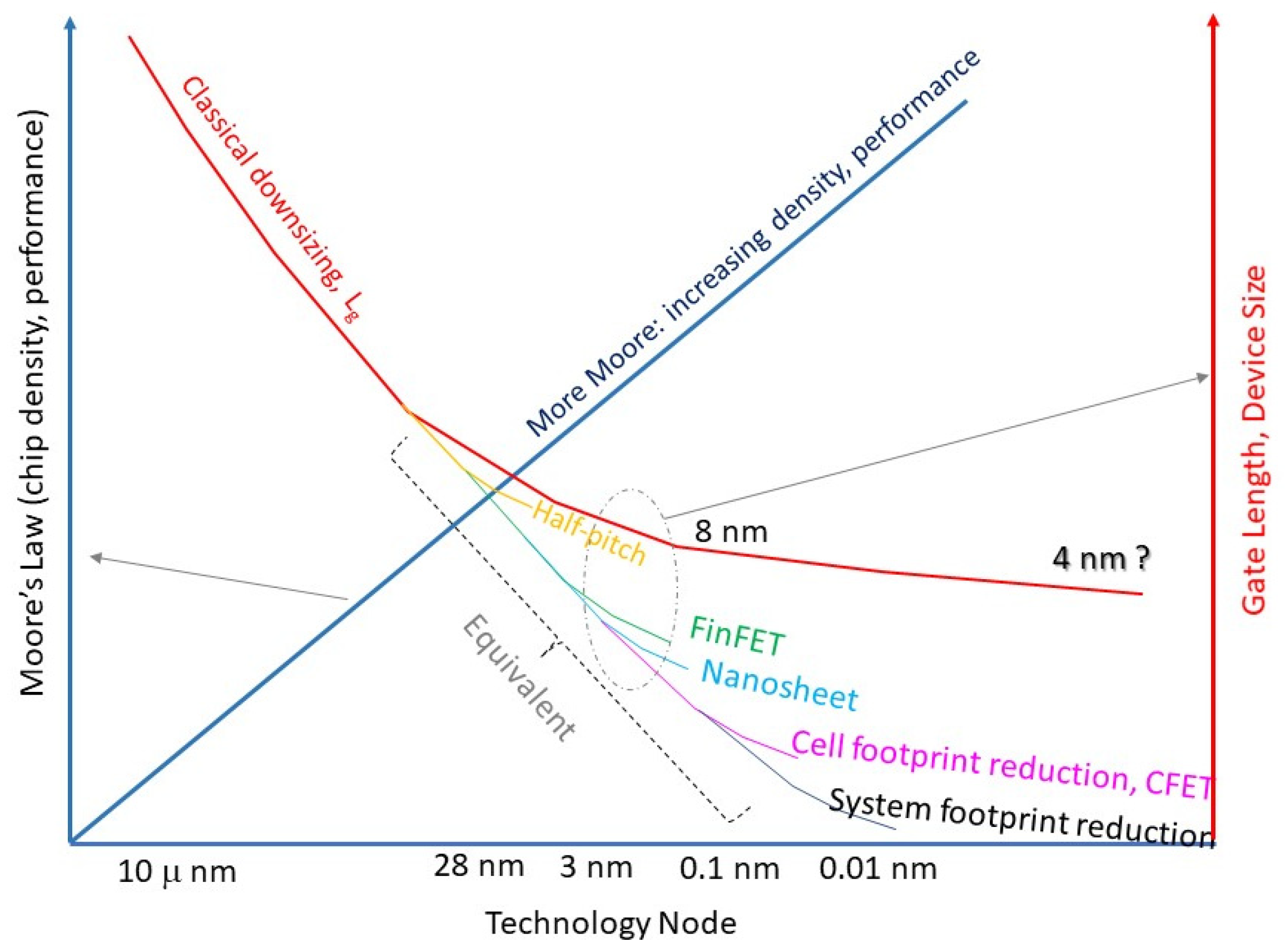
Figure 1. Plot of non-classical or non-Dennard device downsizing schemes towards more Moore for a smaller chip footprint for some near future generations. Adopted from [5].
Electronics 14 03456 g001
Figure 2. The introduction of “More Moore” and “More than Moore” concepts in the White paper for the International Technology Roadmap for Semiconductors [9].
Electronics 14 03456 g002
Figure 3. A different perspective of “More-than-Moore” and “More Moore” proposed by Wong [36].
Electronics 14 03456 g003
Figure 4. Semilogarithmic plot illustrating bit density and stack layer count evolution in commercial NAND flash products over time. Data compiled from multiple industry sources.
Electronics 14 03456 g004
Figure 5. (a) Cross-sectional schematic of a floating-gate flash memory transistor. (b) Illustration of the threshold voltage shift in the IDS-VGS characteristics of the memory transistor after the Floating Gate is filled.
Electronics 14 03456 g005
Figure 6. Comparative cross-sectional views of advanced 3D NAND architectures: (a) Toshiba’s pipe-shaped BiCS (p-BiCS) cell, featuring a U-shaped channel connecting adjacent vertical NAND strings to reduce source line resistance and enhance data retention; and (b) Samsung’s Terabit Cell Array Transistor (TCAT) cell, utilizing a gate-replacement process to mitigate charge loss and lateral diffusion, enabling high-density 3D V-NAND integration.
Electronics 14 03456 g006
Figure 7. Comparison of key performance indicators for the latest-generation NAND flash products. Data from various sources [43,55,56,57,58].
Electronics 14 03456 g007
Figure 8. Current conduction behavior in metal–insulator–metal (MIM) structures under different resistance states. (a) High-resistance state (HRS), where defect-assisted leakage current is minimal. (b) Low-resistance state (LRS), characterized by the formation of conductive pathways. (c,d) Illustrations of the conductive filament model corresponding to HRS (broken filament illustrated as two yellow pillars) and LRS (intact filament illustrated as a single yellow pillar), respectively. (e) Typical access circuit configuration for the memristor.
Electronics 14 03456 g008
Figure 9. Switching characteristics of Resistive Random-Access Memory (RRAM) devices under different operational modes. (a) Unipolar switching: resistance state transitions driven by variations in voltage amplitude or pulse width using a single polarity. (b) Bipolar switching: resistance changes initiated by alternating voltage polarities, with SET and RESET operations triggered by opposite voltage directions.
Electronics 14 03456 g009
Figure 10. Chronological overview of key development milestones in commercializing RRAM and their corresponding fabrication technology.
Electronics 14 03456 g010
Figure 11. (a) Schematic of RRAM crossbar array architecture (a) single layer, (b) two layers, and (c) 3D stacked for in-memory computing [63]. © 2018 Springer Nature. Reproduced with permission.
Electronics 14 03456 g011
Figure 12. Schematic illustration of the tunneling magnetoresistance (TMR) effect within a magnetic tunnel junction (MTJ).
Electronics 14 03456 g012
Figure 13. Schematic illustration showing current flow and magnetization switching dynamics within the Magnetic Tunnel Junction (MTJ) of a Spin-Transfer Torque MRAM (STT-MRAM) cell during write and erase operations.
Electronics 14 03456 g013
Figure 14. Schematic representation of the write operation in an SOT-MRAM cell. Noting that in SOT-MRAM, magnetization switching is achieved via current flowing through an adjacent Spin–Orbit Torque (SOT) metal line, avoiding high current flow through the Magnetic Tunnel Junction (MTJ) itself.
Electronics 14 03456 g014
Figure 15. (a) Schematic of FeRAM cell and (b) FeFET structure and their corresponding changes in current-time of current-voltage characteristics (c,d) with respect to the polarization in the top-down direction (red color) or the bottom-up (blue color) direction. The memory effect of FeRAM could be from a ferroelectric capacitor with a circuit configuration similar to DRAM. For FeFET, the memory effect comes from the gate, a structure similar to a Floating Gate memory transistor.
Electronics 14 03456 g015aElectronics 14 03456 g015b
Figure 16. (a) Polarization characteristics (black curve) and its relation dielectric constant variation (red line) and (b) molecular model of ferroelectric effect in HfO2 unit cell. © 2011 Copyright, American Institute of Physics. Reproduced with permission [83,84].
Electronics 14 03456 g016
Figure 17. Ternary phase diagram illustrating the composition of various phase-change alloys, their year of discovery [90]. © 2007 Copyright Springer Nature. Reproduced with permission.
Electronics 14 03456 g017
Figure 18. Technological evolution of phase-change memory (PCM) across the domains of (a) materials, (b) device structures, (c) commercial products, and applications [94]. © 2025 American Chemical Society. Licensed under CC-BY-NC-ND 4.0.
Electronics 14 03456 g018
Figure 19. Device architecture, circuit model, and switching characteristics illustrating the operation of a typical phase-change memory (PCM) cell. (a) An equivalent circuit model in which the PCM material is represented as a varistor in series with a load resistor (access device). (b) Transmission electron micrographs of a mushroom-type PCM structure in the SET and RESET states. (c) Representative current–voltage (IV) characteristics showing distinct conduction behaviors corresponding to different operational states and phases of the material [94]. © 2025 American Chemical Society. Licensed under CC-BY-NC-ND 4.0.
Electronics 14 03456 g019
Figure 20. PCM cell architecture optimization strategies and their corresponding outcomes. Optimization can be done in two domains: contact area minimization and volume reduction [94]. © 2025 American Chemical Society. Licensed under CC-BY-NC-ND 4.0.
Electronics 14 03456 g020
Figure 21. Qualitative comparison of various non-volatile memory technologies across key metrics: storage capacity, endurance, access speed, energy efficiency, and process maturity. Process maturity encompasses broader manufacturing considerations, including mass-production capability, process complexity, size scalability, CMOS compatibility, system integration potential, and cost-effectiveness.
Electronics 14 03456 g021
Figure 22. Comparison between conventional main memory devices used in current computer systems (top row) and emerging non-volatile memory (NVM) technologies (bottom row) to be used in future computer structures. Among the conventional options, SRAM offers the highest speed, followed by DRAM. However, both are volatile memory technologies and therefore exhibit significantly higher power consumption. The remaining memory types shown are non-volatile. Flash memory operates based on charge storage, whereas the emerging NVM technologies, resistive RAM (RRAM), phase-change memory (PCM), magneto-resistive RAM (MRAM), and ferroelectric memory (FeRAM, FeFET), store information by altering the resistance states, phases, or polarization states of the memory cell.
Electronics 14 03456 g022
Figure 23. (a) Illustration of the fundamental electrical quantities—charge, current, voltage, and magnetic flux—and their relationships, along with the corresponding passive circuit components. The memristor is highlighted as the “missing” fourth fundamental element, establishing a direct relationship between charge and magnetic flux. (b) RRAM and CMOS implementation of material implication, or IMPLY logic, a key Boolean operation, remained largely unexplored until the advent of the memristor.
Electronics 14 03456 g023
Figure 26. Two memristor-based shift register designs. (a) A D-type flip-flop implemented using memristors, applied in a circular shift register architecture [144]. (b) Schematic of a 4-bit shift register constructed with memristor-based logic gates. Modified based on [146].
Electronics 14 03456 g026
Figure 27. Implementation of an 8-bit shift-and-add multiplier based on RRAM IMPLY gates. Modified based on [146].
Electronics 14 03456 g027
Figure 28. (a) Circuit configuration of a memristor-aided full adder (MAD). (b) An 8-bit shift-and-add multiplier based on MAD. Modified based on [146].
Electronics 14 03456 g028
Figure 29. Schematic showing the simplification of a memristor-based multiplier by transforming the multiplication operation into a multi-bit addition using a Multiple Input Multiple Output (MIMO) scheme [147].
Electronics 14 03456 g029
Figure 30. Comparison of traditional computer architectures with ROM, RAM structure (a), and its non-volatile replacement (b).
Electronics 14 03456 g030
Figure 31. Illustration of all non-volatile memory augmented computer architecture.
Electronics 14 03456 g031
Figure 32. (a) Graphics cards represent one of the earliest implementations of near-memory system architecture, utilizing 2.5D packaging technology to position DRAM in close proximity to the GPU. Adopted from Wikipedia.org (https://en.wikipedia.org/wiki/Three-dimensional_integrated_circuit (accessed on 28 June 2025). Three-dimensional integrated-circuit under CC BY-SA 4.0 rule) (b) Near-memory architecture is emerging as a popular solution for high-performance SoC CPUs, enabling the integration of diverse memory blocks with logic units for improved computational efficiency.
Electronics 14 03456 g032aElectronics 14 03456 g032b
Figure 33. (a) Schematic of a linear system solver implemented using an RRAM cross-point array, where red cylinders at intersections represent programmable resistive elements. (b) Corresponding analog circuit representation leveraging Ohm’s law for matrix–vector multiplication and inverse function evaluation using a transimpedance amplifier. Reprinted with permission from [158]. © 2020 Springer Nature. Reproduced with permission.
Electronics 14 03456 g033
Figure 34. Scalability of crossbar-based memristor arrays for machine learning and scientific computing applications. (a) Accuracy enhancement using a bit-slicing technique for multi-bit operations. (b) Mixed-precision in-memory computing approach for iteratively refining computation results [157]. © 2020 Springer Nature. Reproduced with permission.
Electronics 14 03456 g034aElectronics 14 03456 g034b
Figure 35. Emulation of synaptic behavior using phase-change memory (PCM) synapses. The left panel illustrates the synthesis of neuronal synaptic action through PCM-based spike-timing-dependent plasticity (STDP), while the right panel shows a strong correlation between the emulated results and experimentally measured biological data [161]. © 2011 American Chemical Society. Reproduced with permission.
Electronics 14 03456 g035
Figure 36. Illustration of a large-scale RRAM-based in-memory computing architecture for deep learning applications. (a) The system integrates multiple cross-point arrays and peripheral circuits to enable highly parallel operations. (b) Illustration of RRAM cross-point array for efficient matrix–vector multiplication. (c) Application in scalable neural network [157]. © 2020 Springer Nature. Reproduced with permission.
Electronics 14 03456 g036
Table 1. Comparison of performance metrics, device parameters, and integration features of various non-volatile memory technologies [42].
STT MRAM
SCM/
DRAM
MRAM EmbeddedSOT
Cache
PCM Stand
Alone
PCM
Embedded
RRAM Stand
Alone
RRAM EmbeddedFeRAMFeFET
Capacity>1 Gb10–100 Mb>1 MbGb10–100 Mb~Gb
targetted
1–10 MbPoorSmall
ScalabilityMediumMediumPoorGoodGoodMediumGoodMediumPoor
MLCNoNoNoPossiblePossiblePossiblePossiblePossiblePossible
3D
Integration
NoNoNoYesYesYesYesNoNo
ArchitectureXbarXbar3 terminalsXbar1T1RXbar1T1R1T1R3 terminals
Retention>1 yr 100 °CAutomotive
150 °C 10 ys
85–100 °C85–100 °CAutomotive10 yrs 85 °C10 yrs > 85 °C85–100 °CSMT
compliant
Latency10 ns10 ns<1 ns100 ns100 ns100 ns100 ns<20 ns5 ns
PowerpJ/bitpJ/bitfJ/bit10 pJ/bit10 pJ/bit
>200 uA
1–10 pJ/bit1–10 pJ/bit
~100 uA
10 fJ/bit10 fJ/bit
Endurance1010>106>1010107106107106>1011
(destructive
read)
104–105
VariabilityNANANAIssue (drift)Issue (drift)Issue
(variability,
noise)
Issue
(variability,
noise)
Variability
@small size
Variability
@small size
SpaceDRAMNVMCacheSCM
(storage,
memory)
MPU, MCUSCM
(storage,
memory)
MPU, MCUDRAMFlash
Maturity
Example of
products
Products: Everspin, Avalanche (persistent SRAM)Product: Avalanche, TSMC (offers STTMRAM)No
product
Products:
Intel/
Micron,
Intel
Products:
sampling: ST
Microelectronics
No
product
Products:
Panasonic,
Dialog,
TSMC
Products (PZT): Texas
Instruments,
ujitsu,
Cypress
Good
Disclaimer/Publisher’s Note: The statements, opinions and data contained in all publications are solely those of the individual author(s) and contributor(s) and not of MDPI and/or the editor(s). MDPI and/or the editor(s) disclaim responsibility for any injury to people or property resulting from any ideas, methods, instructions or products referred to in the content.