Abstract
The flexible DC transmission project of renewable energy has become an inevitable development trend for large-scale renewable energy grid connection. A two-terminal weak feed (TTWF) AC system is often composed of 100% power electronic equipment. The traditional fault control strategy adopted after a fault in the converter at both terminals of the line limits the fault current and controls the phase, resulting in a decrease in the time-domain distance protection performance. This paper first analyzes the adaptability challenges of time-domain distance protection in TTWF. Based on detailed fault characteristic studies, two improvement approaches are proposed: (1) accounting for phase control effects by equivalently modeling the fault impedance as a series combination of fault resistance and inductance; and (2) incorporating distributed capacitance effects through fault differential equation derivation based on π-type line equivalent models. A novel time-domain distance protection method is subsequently developed, comprehensively considering control strategy impacts and distributed capacitive currents. Simulation tests verify that the proposed method maintains reliable operation under severe conditions, including 300 Ω fault resistance and 30 dB white noise interference, demonstrating significantly improved resistance to fault impedance and noise compared to conventional solutions.
1. Introduction
Currently, the installed capacity of renewable energy in China is rapidly increasing [1]. Against the backdrop of large-scale renewable energy base grid integration and flexible DC transmission projects, several landmark projects have emerged, such as the Nan’ao multi-terminal project, the Rudong offshore wind project, and the Qingzhou V/VII flexible DC projects [2,3]. In these projects, both terminals of the AC transmission lines are weak-feed power sources. Due to the inherent advantages of power electronic devices, they are widely utilized in renewable energy generation, leading to power systems increasingly characterized by high proportions of renewable energy and high proportions of power electronics [4,5]. The combined effects of weak-feed power sources at both ends result in complex electromagnetic and control response time-varying processes during system faults. The fault characteristics of TTWF AC systems differ significantly from those of synchronous generator systems, rendering protection principles based on traditional synchronous generator fault characteristics potentially inadequate [6,7,8]. Moreover, system fault characteristics are influenced by converter control strategies, and different fault control strategies produce distinct fault signatures. Therefore, researching improved AC protection methods that account for converter fault control strategies is crucial for ensuring the large-scale integration of renewable energy.
Renewable energy collection and transmission lines are typically long and operate at high voltage levels in the desert, Gobi, and barren regions. Time-domain distance protection can provide fault location after a fault occurs in a TTWF AC system, making it indispensable for line protection [9]. Regarding the adaptability of time-domain distance protection in TTWF AC systems, the authors of [10] analyze the impact of power frequency components in transmission lines on distance protection under different fault conditions. The results show that converter control strategies and fault conditions affect both the magnitude and phase angle of the equivalent sequence impedance of wind farms and the system [9,10]. The authors of [11] found that the integration of a large number of inverter-based power sources, such as photovoltaic and energy storage systems, into the grid significantly interferes with traditional distance protection, posing risks of refusal to operate or maloperation. Ref. [12] analyzes the adaptability of power-frequency distance protection in TTWF AC systems, revealing that due to the high harmonic content in the short-circuit current after a fault, Fourier algorithms fail to extract accurate power-frequency information, thereby preventing precise measurement of impedance.
Regarding research on improvements to time-domain distance protection, the authors of [13] analyze the limitations of distance protection in TTWF AC systems and propose an adaptive distance protection algorithm that jointly considers fault distance and fault resistance parameters. This algorithm achieves distance protection by combining locally measured electrical quantities with iterative computations. Other studies [14,15] introduce a protection algorithm based on fault-point voltage reconstruction. Ref. [16] proposes fault location estimation using an empirical mode decomposition-based random forest algorithm and an improved impedance method. However, such complex algorithms involve substantial computational burden and slower processing speeds, making it difficult to meet the rapid response requirements of protection systems. Ref. [17] addresses the insufficient tolerance of distance protection to fault resistance by proposing a new principle based on a parameter identification model. After a fault, the distinction between internal and external faults becomes significant, allowing the parameter identification principle to enhance the fault resistance tolerance of distance protection, ensuring reliable operation even under high-resistance fault conditions. The authors of [18] analyze the adaptability of power-frequency distance protection in weak-feed systems based on an R-L equivalent line model, considering factors such as model errors, data transmission, synchronization errors, and data window length, and propose an improved time-domain distance protection algorithm. Ref. [19] examines the impact of fault resistance and converter fault output characteristics on power-frequency distance protection performance and introduces a time-domain distance protection algorithm based on actual recorded fault data, which remains unaffected by post-fault converter output characteristics. Other studies [20,21] investigate the adaptability of distance protection in single-terminal weak-feed AC systems, analyzing the influence of fault resistance magnitude on fault current characteristics. The authors suggest treating fault resistance as an unknown variable in the time-domain fault differential equation to validate distance protection performance in weak-feed systems. Ref. [22] models the fault branch in the zero-sequence fault component network as a resistive–inductive (R-L) circuit. By combining the full time-domain network and zero-sequence fault component network, it derives a time-domain fault differential equation and uses the least squares method to accurately solve for three unknown variables, thereby improving fault resistance tolerance. Ref. [23] leverages the negative-sequence current suppression control strategy of renewable energy-side converters, which results in an open-circuit characteristic in the negative-sequence network of the composite sequence network. It reconstructs a fault distance equation to address the adaptability issue of distance protection in TTWF AC systems. Ref. [24] considers the inductive or capacitive nature of fault resistance (i.e., phase-controlled characteristics) and divides post-fault resistance into equivalent fault resistance and equivalent fault inductance. However, it neglects the impact of distributed capacitive current on time-domain distance protection for long-distance AC transmission lines. Ref. [25] accounts for large phase-angle differences between the two terminal systems and constructs time-domain distance protection based on the R-L line model under active injection. However, this approach only applies to asymmetrical faults and does not consider the influence of line distributed capacitance.
In summary, existing improved distance protection methods for TTWF AC systems exhibit various shortcomings, specifically the following:
- (1)
- Limited system generality—further validation is required.
- (2)
- Insufficient consideration of fault control strategy effects.
- (3)
- Inadequate accounting for line distributed capacitance effects.
This paper addresses the aforementioned three issues by focusing on a TTWF AC system in the context of large-scale renewable energy transmission via flexible HVDC. A time-domain distance protection method is proposed for such systems, taking into account control strategies and the influence of distributed capacitive current.
The method first considers phase control by equivalently modeling the fault resistance as a series combination of resistance and inductance. Next, it accounts for the distributed capacitive current of long-distance transmission lines, deriving a fault differential equation based on the π-type line equivalent model. Finally, an electromagnetic transient simulation model of a TTWF AC system for photovoltaic plant transmission via flexible HVDC is established in PSCAD/EMTDC. Extensive simulations verify the performance and reliability of the proposed improved method.
2. Adaptability Analysis of Time-Domain Distance Protection
2.1. Basic Principles of Time-Domain Distance Protection
Taking a three-phase metallic fault in the system as an example, the time-domain fault loop equation on the M-side can be expressed as:
where Rk and Lk represent the equivalent resistance and equivalent inductance from the protection installation point to the fault location, respectively.
Equation (1) contains only two unknowns, Rk and Lk, both of which can be expressed through a single unknown parameter—the fault distance d. By formulating and solving the fault differential equations for Rk and Lk, the fault distance can be determined.
When a TTWF AC system line adopts negative-sequence current suppression control strategies for its converters, let us consider a single-phase grounding fault as an example. The negative-sequence components at both terminals are influenced by the negative-sequence control, resulting in open-circuit conditions in the negative-sequence networks of the composite sequence network. This leads to overvoltage issues in the non-faulted phases of the TTWF AC system. To address this, this paper modifies the MMC negative-sequence current suppression control strategy to a coordinated negative-sequence voltage suppression and step-down V/F control, thereby preventing overvoltage damage to power electronic devices.
After the control strategy improvement, the interaction of positive- and negative-sequence control strategies in the TTWF AC system introduces a phase difference between the fault currents flowing toward both sides of the fault point. This increases the error in fault distance calculations using traditional time-domain distance protection. Consequently, it is necessary to account for the influence of control strategies on the phase characteristics of fault currents and to improve the principles of time-domain distance protection.
2.2. Theoretical Adaptability Analysis of Time-Domain Distance Protection
From Equation (1), it can be observed that the operating principle of the time-domain distance protection element is line-oriented and does not require Fourier algorithms to extract power–frequency components. Consequently, this protection scheme is theoretically immune to frequency deviation characteristics of power electronic systems (e.g., renewable energy sources) and offers fast tripping speeds.
For time-domain distance protection, current research predominantly focuses on the R-L line equivalent model, neglecting the influence of distributed capacitance. This simplification introduces significant errors. Additionally, algorithmic errors in the fault distance calculation cannot be ignored. The difference approximation for differentiation is the most common method to handle differential terms in fault equations, yet it introduces computational errors, particularly during transient processes in the initial fault stage. Furthermore, the selection of the data window length affects computational stability and convergence speed. Generally, longer data windows reduce result fluctuations and enhance stability but degrade convergence speed. Sampling rates also critically impact algorithm precision.
In power system fault analysis, lines are typically simplified as resistance–inductance (R-L) models, where distributed capacitance is disregarded. From circuit theory, this model holds for fundamental, harmonic, and non-periodic components but fundamentally represents a lumped approximation of distributed parameters. Such simplification is valid only within specific frequency ranges. When analyzing high-frequency components (particularly harmonics dominated by distributed capacitance), the R-L model deviates significantly from actual physical characteristics. This limitation reduces model accuracy and impairs the ability of protective relays to accurately extract and discriminate fault features.
Moreover, time-domain distance protection exhibits limited fault resistance tolerance. For non-metallic faults (taking a three-phase fault as an example), the time-domain equation on the M-side can be expressed as:
In this equation, due to the TTWF characteristics of converter devices, the additional term is generally large, causing substantial deviations between calculated values Rk and Lk and actual values.
For high-resistance single-phase grounding faults (e.g., Phase A), the corresponding time-domain fault loop equation on the M-side is:
where , denote compensation coefficients for zero-sequence resistance and inductance, respectively. The large additional term may lead to misoperation of time-domain distance protection in high-resistance single-phase fault scenarios.
As shown in Figure 1, both positive- and negative-sequence components are controlled. From Figure 1:
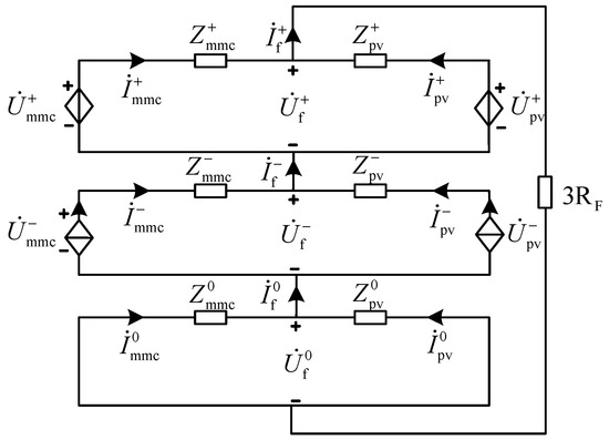
Figure 1.
Single-phase ground fault equivalent sequence network.
The fault current derived from Equation (4) is:
From Figure 1 and Equation (4), the magnitudes of positive- and negative-sequence components post-fault are determined by the control strategies of the TTWF AC system, while the zero-sequence component depends on the fault type and transformer winding configuration. However, coupling exists among positive-, negative-, and zero-sequence components in the fault sequence network. Consequently, the control actions of positive/negative sequences indirectly influence zero-sequence components, resulting in phase discrepancies between positive/negative-sequence currents on both sides of the fault point [26]. These phase inconsistencies further propagate to zero-sequence currents, significantly increasing errors in fault distance calculations by time-domain distance protection.
2.3. Adaptability Simulation Analysis of Time-Domain Distance Protection
To verify the adaptability of conventional time-domain distance protection based on the R-L model in the TTWF AC systems, the following analyzes the adaptability of conventional time-domain distance protection under different fault resistances at the same fault location and different fault locations with the same fault resistance.
- A.
- Different Fault Resistances
As shown in Figure 2, taking a single-phase ground fault (Phase A) at the midpoint of the line as an example, the least squares method is used to calculate and compare the performance of traditional distance protection as the fault resistance increases.
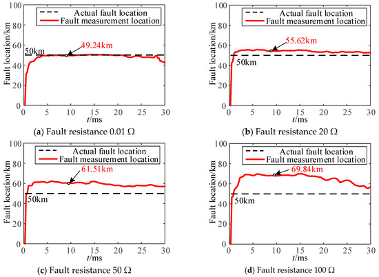
Figure 2.
Comparison of time-domain distance protection fault location with fault resistance in single-phase grounding fault.
When a single-phase ground fault occurs in the TTWF AC system, both line-side converters adopt a negative-sequence current suppression control strategy. Figure 2 shows that under traditional control strategies and conventional time-domain distance protection, the error in fault location calculation increases significantly as the fault resistance grows. When the fault resistance reaches 50 Ω, the calculated fault location deviates from the actual position by over 10 km, exceeding a 10% error margin. Thus, conventional time-domain distance protection under traditional control strategies cannot meet the requirements of the TTWF AC systems.
- B.
- Different Fault Locations
As shown in Figure 3, with a fixed fault resistance, the least squares method is used to compare calculated and actual fault locations under varying fault positions for a single-phase ground fault (Phase A) at the line midpoint.
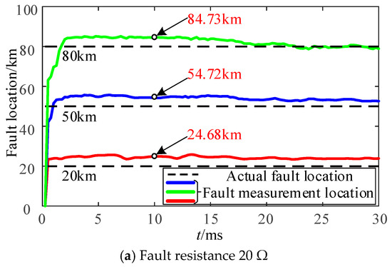
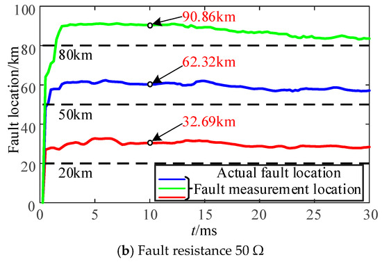
Figure 3.
Comparison of time-domain distance protection ranging results with fault location under single-phase grounding fault.
Under the same negative-sequence current suppression control strategy, Figure 3 demonstrates that the fault location calculation error does not vary significantly with fault positions when the fault resistance remains constant. However, distinct fault resistances lead to noticeable differences in calculation errors.
In summary, time-domain distance protection exhibits adaptability issues in the TTWF AC systems. When both converters adopt negative-sequence current suppression control, the protection performs well for metallic faults but degrades significantly as fault resistance increases. Therefore, improvements to fault control strategies and distance protection principles are necessary, specifically tailored for TTWF AC systems.
Compared to phasor-based distance protection, time-domain distance protection eliminates the need for Fourier algorithms to extract phase and amplitude information, avoiding frequency offset impacts. It also operates faster, reducing post-fault overvoltage/overcurrent damage to power electronics and minimizing stability and power quality risks. Hence, this study focuses on enhancing time-domain distance protection.
Beyond fault resistance, distributed capacitive currents in long-distance transmission lines critically affect time-domain distance protection performance. This influence grows with line length, making it non-negligible in long-distance AC collection systems (e.g., large-scale desert-based renewable energy systems). Considering converter control strategies and distributed capacitance effects, this paper proposes an improved time-domain distance protection method for TTWF AC systems, integrating control strategy adjustments and capacitive current compensation.
3. Improved Time-Domain Distance Protection Method Considering Control Strategies and Distributed Capacitance Current Effects
Existing time-domain distance protection methods primarily address performance degradation caused by phase differences in line-end currents during faults. However, conventional methods typically calculate fault currents using only local current measurements at the protection device. For high-resistance faults, this approach introduces significant errors, which worsen as the fault resistance increases. Notably, traditional time-domain distance protection relies on fault differential equations derived from the R-L line model, which neglects distributed capacitance effects. In long-distance transmission lines, distributed capacitance significantly impacts protection performance, and fault characteristics in TTWF AC systems are further influenced by converter control strategies at both ends. To address these limitations, this paper proposes an improved post-fault cooperative control strategy for TTWF AC systems and introduces a time-domain distance protection method based on a π-type equivalent line model. The method incorporates distributed capacitance into the fault differential equations and models the fault resistance as a complex impedance to mitigate the impact of phase differences between line-end currents on fault location accuracy.
3.1. Implementation Framework
- A.
- Analysis of Factors Affecting Time-Domain Distance Protection Adaptability
Firstly, as discussed in Section 3.2, fault currents in TTWF AC systems are inherently limited due to weak fault characteristics. To enhance system stability and amplify post-fault signatures, this paper adopts a negative-sequence current suppression control strategy for the renewable energy-side converter and the step-down V/F control with negative-sequence voltage suppression for the modular multilevel converter (MMC). These strategies ensure system stability while improving fault detectability. Rapid protection operation is critical to minimize overvoltage/overcurrent damage to power electronic converters and reduce stability/power quality risks, making enhanced time-domain distance protection essential.
Secondly, the phase-controlled nature of TTWF AC systems introduces uncertainties in fault current phase differences between line ends. Since distance protection relies solely on single-ended measurements, the unknown phase/amplitude of the remote-end current degrades reliability. To address this, the fault resistance is modeled as a complex impedance (split into resistive and inductive components), effectively decoupling phase difference effects from fault location calculations.
Thirdly, traditional R-L line models fail to account for distributed capacitance in long-distance lines. To resolve this, the proposed method adopts a π-type equivalent line model, deriving fault differential equations that incorporate distributed capacitance. Additionally, the choice of differential equation-solving algorithms and data window lengths significantly impacts protection accuracy, necessitating careful optimization.
- B.
- Overall Implementation Strategy
The improved time-domain distance protection framework for TTWF AC systems, as illustrated in Figure 4, comprises four key steps:
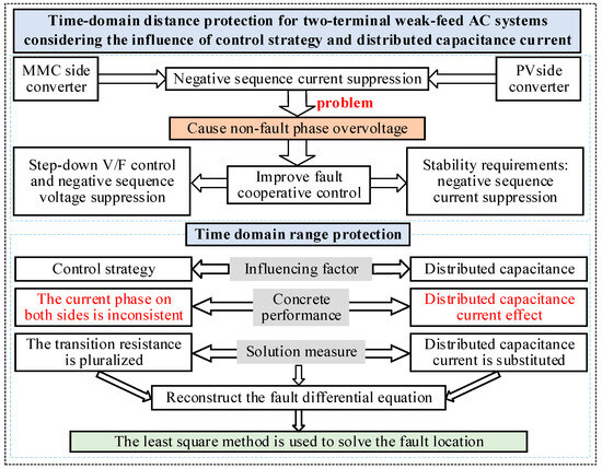
Figure 4.
Time-domain distance protection performance improvement overall process framework.
- To improve the fault control strategy of the TTWF system, this paper adopts a negative-sequence current suppression control strategy on the new energy side converter, while the MMC employs a coordinated control strategy combining step-down voltage V/F control and negative-sequence voltage suppression. This control strategy can meet both the system stability requirements and the protection needs for fault characteristics.
- Considering the phase-controlled characteristics of the TTWF system, the fault current term in the distance protection differential equation that includes the fault resistance is modified from a real part to a complex term, i.e., it is decomposed into fault resistance and fault inductance components. This adjustment effectively mitigates the impact of system characteristics on distance protection.
- A time-domain distance protection differential equation is derived based on the π-type equivalent line model. The resulting time-domain distance protection equation ensures sufficient accuracy in fault location calculation for the TTWF system.
- An appropriate algorithm for solving the differential equation is selected, taking into account factors such as system sampling rate, fault location accuracy requirements of time-domain distance protection, and data window length—all of which influence the performance of time-domain distance protection.
The above four considerations are based on factors such as the diversity of converter control strategies in the TTWF system, the unique characteristics of the TTWF system, differences in line models, and variations in algorithms for solving differential equations—all of which influence time-domain distance protection. Based on these four aspects, improvements are made to time-domain distance protection to enhance the performance of single-ended distance protection.
3.2. Formulation of Fault Differential Equations Considering Control Strategies and Distributed Capacitance Current Effects
When a single-phase ground fault (e.g., Phase A) occurs in the TTWF AC system shown in Figure 5, fault currents from the renewable energy-side converter and MMC flow into the fault point. To enhance distance protection performance, the distributed capacitance current effects in long-distance transmission lines are incorporated using the π-type equivalent line model. The simplified post-fault equivalent circuit is illustrated in Figure 5.

Figure 5.
Single-phase (AG) ground fault equivalent circuit based on π-type line equivalent model.
From Figure 5, the fault differential equation considering distributed capacitance is formulated as Equation (6):
where and are the time-domain voltage and current of Phase A at the renewable-side protection terminal; and are the positive-sequence resistance and inductance per unit length; and is the voltage across the fault resistance.
Here, is expressed as:
In TTWF AC systems, the phase angles of sequence voltages and currents vary dynamically post-fault. To address phase difference uncertainties, the fault resistance is modeled as a complex impedance:
Thus, Equation (7) becomes:
We express the fault resistance as a complex quantity:
In the formula, A and B are real coefficients, and and represent the equivalent fault resistance and equivalent fault inductance, respectively.
As can be seen from Equations (4)–(10), the fault resistance can be decomposed into an equivalent fault resistance plus an equivalent fault inductance . The equivalent circuits before and after the decomposition of the fault resistance are illustrated in Figure 4, Figure 5 and Figure 6a and Figure 4, Figure 5 and Figure 6b, respectively, where and are unknown quantities.
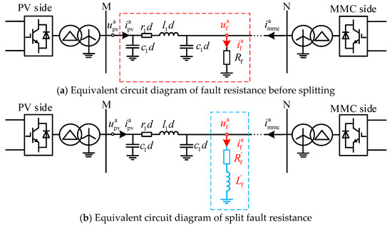
Figure 6.
Equivalent circuit diagram of fault resistance before and after splitting.
Substituting Equation (10) into Equation (9) yields the modified single-phase ground fault differential equation:
Incorporating the effects of distributed capacitance current in long-distance transmission lines while accounting for fault resistance produces Equation (12).
where ; .
In Equation (12), the parameters , , and can be directly obtained from line parameters and data acquisition devices at the renewable energy-side protection installation. However, the fault-point voltage in Equation (12) cannot be directly measured by the protection terminal’s acquisition equipment. Instead, it requires analyzing the fault loop between the local system and the fault point post-fault and formulating the Kirchhoff Voltage Law (KVL) equation for the fault loop. The fault-point voltage is then derived as:
where is the zero-sequence current flowing into the fault point in the fault loop.
Using the symmetrical component analysis method, the fault relationship between the zero-sequence voltage at the protection installation location and the zero-sequence voltage at the fault point can be obtained:
Based on Equation (14), the zero-sequence fault loop can be derived as shown in Figure 7.
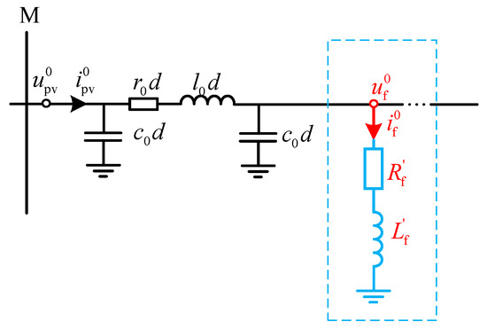
Figure 7.
Zero-sequence equivalent circuit in single-phase ground fault.
From Figure 7, the zero-sequence current at the fault point can be obtained as:
Based on the above derivation, the fault differential equation can be obtained as:
Given that the distributed capacitance of cable lines is typically on the order of μF/km, while that of overhead lines is generally at the nF/km level, and the influence of distributed capacitance on lines is closely related to environmental conditions, line design parameters, operating conditions, and voltage levels—high-voltage lines exhibit even lower distributed capacitance due to their thicker insulation layers—and considering that the research focus of this paper is on new energy development in the Sha-ge-huang region where lines are predominantly overhead, the squared term of distributed capacitance in Equation (16) is negligible and has minimal impact on the final fault location calculation results. Consequently, the squared term involving distributed capacitance in Equation (16) can be omitted, and the simplified form of Equation (16) becomes:
By separating the unknown parameters and known quantities in Equation (17), the final expression of the differential equation for the single-phase-to-ground fault can be obtained as:
where:
In Equation (18): The unknown quantities are the fault distance d, the equivalent fault resistance , and the equivalent fault inductance . These three variables remain constant after the fault occurs. At this point, the unknown variables can be determined by solving the fault differential equation algorithmically using the sampled voltage and current data obtained from the protection installation location.
Similarly, the derivations for two-phase-to-ground faults, three-phase interphase faults, and three-phase-to-ground faults follow analogous principles, which will not be elaborated here.
3.3. Solution of Time-Domain Distance Protection Fault Differential Equation
Based on the theoretical derivation of time-domain distance protection for single-phase grounding faults and two-phase phase-to-phase faults in Section 3.2, it is known that the post-fault differential equations contain three unknown quantities d, , and . The voltage and current data in these differential equations can be obtained through measurements collected at the protection installation point on the new energy side. By utilizing multiple sets of sampled data acquired through measurement, the solution of the fault differential equations can be achieved. Since the sampled voltage and current data are discrete values, the differential terms in the equations are calculated using the difference method to approximate differentiation. Assuming a sampling interval of Ts, the differential terms can be computed according to Equation (19).
Taking the A-phase grounding fault as an example, based on Equations (18) and (19), the fault differential matrix equation under multiple sets of sampled data can be derived as:
where:
In Equation (20), the left side represents the voltage data collected at the protection installation point, while the right side represents the voltage fitted by formulating the Kirchhoff Voltage Law (KVL) equation for the fault loop using locally measured voltage and current data. The equation contains three unknown variables, d, , and , and the difference between the two sides of the equation corresponds to the error between the actual measured values and the fitted values of the unknowns. In Equation (20), represent the information matrices composed of sampled voltage and current values collected at the local protection installation point, respectively, while denote the first-order and second-order derivative matrices of the locally measured voltage and current data. Based on the least squares method, when the cumulative error calculated from multiple sets of sampled data is minimized, the computed results for the unknown variables are considered equivalent to the actual measured data. In summary, the objective function for solving the fault differential equation can be formulated as:
For the objective function of the fault differential equation solution, the minimum value can be determined by setting the partial derivatives of the cumulative error with respect to the unknown variables d, , and to zero, as shown in Equation (22).
Through the above analysis, it can be concluded that by utilizing the voltage and current data collected at the local protection installation point, the unknown variables in the fault differential equation, constructed based on the influence of distributed capacitance and the current phase difference across the fault point, can be solved. This approach addresses the requirements of TTWF AC systems for rapid protection and accurate fault location.
3.4. Implementation Process of the Improved Time-Domain Distance Protection Method
In summary, this section derives the time-domain distance protection fault differential equations by considering the effects of distributed capacitance and the phase difference between currents on both sides, based on the π-type line equivalent model. The flowchart for protection distance determination is shown in Figure 8. In the figure, the parameter a represents the difference between the fault distances calculated from interval samples, defined as , where k denotes the k-th sampling point, is the corresponding sampling time, and this study assumes the fault occurs at time zero. The detailed implementation steps of the time-domain distance protection are as follows:
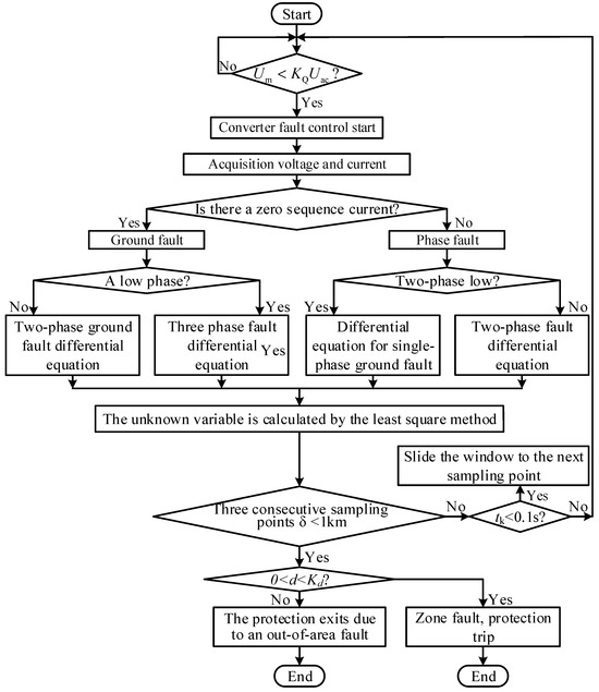
Figure 8.
Improved time-domain distance protection flow chart.
Post-Fault Procedure: After a fault occurs, voltage and current signals are captured at the protection installation point. The converter detects the fault by analyzing the voltage signal and switches from normal steady-state operation to a fault cooperative control strategy between the converters on both sides, based on the magnitude of the voltage sag.
Data Processing and Fault Identification: The protection system on the renewable energy side collects local voltage and current data and extracts components within specific frequency bands using a bandpass filter. The filtered voltage and current signals are then analyzed to check for the presence of a zero-sequence component in the current. A detected zero-sequence component indicates a ground fault, while its absence suggests a phase-to-phase fault. Further classification (e.g., single-phase-to-ground, two-phase-to-ground, two-phase, or three-phase fault) is determined by the number of phases experiencing voltage sags.
Fault-Specific Equation Activation: Based on the identified fault type, the corresponding fault differential equation is activated. The equation is solved numerically using the least squares method to estimate the fault parameters.
The application of the least squares method requires consideration of the impact of data window length and sliding window length on the precision of calculation results. For differential terms in fault differential equations, this study employs the finite difference approximation method, necessitating sliding window calculations. When the sliding window contains only two data points, the calculation accuracy fails to meet the requirements of the proposed time-domain distance protection. However, when the sliding window exceeds one power frequency cycle (20 ms), the computational error no longer decreases significantly.
To balance both the rapid response of the time-domain distance protection algorithm and computational accuracy, this paper selects a sliding window length of half a power frequency cycle (10 ms). This configuration ensures that the protection algorithm begins outputting calculated unknown parameters after half a power frequency cycle following the fault occurrence, achieving an optimal trade-off between speed and precision.
When three consecutive fault location calculation results satisfy the condition , the calculation is deemed reliable. Based on comparing the calculated fault location with the protection action criteria, it can determine whether the fault is an internal fault and whether protection should operate. If any one of the three consecutive results fails to meet , the calculation is considered unreliable, requiring additional data points for continuous validation. If the fault calculation results meet the above conditions within 100 ms after protection activation, the protection system resets entirely.
4. Simulation Case Studies: Validation and Analysis
To validate the performance of the improved time-domain distance protection for TTWF AC systems under fault conditions, this section analyzes the proposed enhanced method, which accounts for control strategies and the influence of distributed capacitive currents, across various operating scenarios. All simulation data below are sourced from experimental data of major scientific and technological projects at the Southern Power Grid Research Institute. The data is detailed and traceable, ensuring the reliability and effectiveness of the protection improvement methods proposed in this article. The proposed protection has a data window of 10 ms. When using an Intel® Core™ i5-9500 processor with a main frequency of 3.00 GHz for calculations, the algorithm’s computation time, Tca, is less than 0.3 ms. Therefore, the protection can identify faults within approximately 11 ms. By comparing the data window length of the protection algorithm, it can be approximately assumed that it is the same as the fault recognition time of the protection. The system was modeled using PSCAD 4.6.2 (64 bit) Professional version in the article.
4.1. Simulation Analysis of Protection Performance Under Different Fault Resistances
Taking the single-phase-to-ground fault (AG) at midpoint f2 of the TTWF AC transmission line as an example: To validate the performance of the proposed improved time-domain distance protection method for the TTWF AC systems—which accounts for control strategies and distributed capacitive currents—a single-phase-to-ground (AG) fault at the midpoint f2 of the line is simulated under varying fault resistances (0.01 Ω, 100 Ω, 200 Ω, 300 Ω). The sliding window length for the least squares method is set to 10 ms. The impact of different fault resistances on the performance of the proposed method is illustrated in Figure 9.
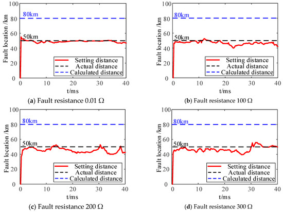
Figure 9.
Improved time-domain distance protection performance under different fault resistances.
According to Figure 9, for internal faults, the calculated fault distances using the proposed improved time-domain distance protection method fluctuate near the actual fault location as the fault resistance increases. When the fault resistance is below 100 Ω, the proposed method rapidly converges to a fault position close to the actual fault point. Even under high fault resistance conditions (200 Ω and 300 Ω), the algorithm maintains its capability to quickly identify the fault location. The average calculated fault distances at fault resistances of 0.01 Ω, 100 Ω, 200 Ω, and 300 Ω are 48.92 km, 46.50 km, 45.48 km, and 46.78 km, respectively, demonstrating reliable identification of internal faults with errors well within the acceptable range of time-domain distance protection standards.
As shown in Figure 10, the proposed improved time-domain distance protection method modifies the fault differential equations by incorporating the effects of enhanced converter fault control strategies and distributed capacitive currents. When single-phase-to-ground (AG) faults occur at different locations, the improved method is used to calculate the fault distance. The simulation results demonstrate that, even under a high fault resistance of 300 Ω, the proposed method rapidly converges to the fault location across all tested positions, with errors remaining within the permissible range of time-domain distance protection.
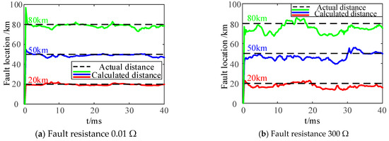
Figure 10.
Simulation results of different fault locations.
4.2. Simulation Analysis of Protection Performance Under Different Fault Locations
The proposed improved time-domain distance protection method in this study enhances the conventional approach by modifying the converter control strategy and incorporating the effects of both control dynamics and distributed capacitive currents into the fault differential equations. A least squares algorithm is then applied to solve for the fault location. To evaluate the performance of this enhanced method under varying fault positions, single-phase-to-ground faults (AG) were simulated at three locations near the renewable energy side: 20 km, 50 km, and 80 km. The analysis focused on validating the method’s consistency under the same fault resistance, with results illustrated in Figure 10.
4.3. Simulation Analysis of Protection Performance Under Different Fault Types
To verify the performance of the proposed time-domain distance protection in the TTWF AC systems during symmetric and asymmetric faults, asymmetric faults (e.g., single-phase-to-ground fault, AG) are set at the midpoint of the line within the protected zone. Symmetric faults (e.g., three-phase phase-to-phase fault, ABC) are also set at the midpoint of the line within the protected zone. The simulation results of the time-domain distance protection under different fault types are shown in Figure 11.

Figure 11.
Simulation results of different fault types.
As shown in Figure 11, during different types of internal faults, the proposed time-domain distance protection method demonstrates reliable performance: for single-phase-to-ground faults, the calculated fault distance has an average value of 48.92 km with an absolute error of 1.08%; for three-phase phase-to-phase faults (A-phase), the calculated fault distance is 49.74 km with an absolute error of 0.26%, and the fault distance is rapidly calculated after fault occurrence. Additionally, the protection range of Zone I distance protection covers 80% of the total line length, and the proposed method consistently identifies internal faults across all tested fault types, with results meeting the requirements of Zone I distance protection.
4.4. Comparative Analysis of Time-Domain Distance Protection Performance Before and After Considering Distributed Capacitance Effects
According to the verification and analysis in Section 4.1, Section 4.2 and Section 4.3, this paper adopts a negative-sequence current suppression control strategy at the renewable energy-side converter of the TTWF AC system, while the MMC employs a coordinated control strategy combining step-down V/F control with negative-sequence voltage suppression. Compared with the configuration where both terminal converters of the TTWF AC system adopt negative-sequence current suppression control strategies, this approach yields smaller fault location errors in time-domain distance protection calculations. This section verifies the performance differences between time-domain distance protection criteria derived from two fault differential equation models when implementing the aforementioned control strategies: one based on the line R-L equivalent model and the other considering line distributed capacitance through a π-type equivalent model. Taking a single-phase-to-ground (AG) fault at midpoint f2 of the line as an example, the simulation results are shown in Figure 12.
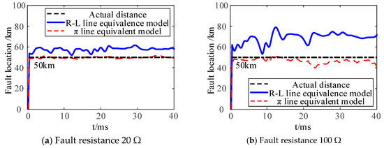
Figure 12.
The time-domain distance protection performance of the distributed capacitor is considered.
As illustrated in Figure 12, a comparative analysis of fault distances calculated by time-domain distance protection based on different line equivalent models reveals that, with a fault resistance of 20 Ω, the average fault distance at 20 ms derived from the R-L equivalent line model is 57.56 km, while the π-type equivalent line model provides a more accurate fault location of 49.75 km. When the fault resistance increases to 100 Ω, the fault location based on the R-L equivalent model rises to 68.97 km, whereas the π-type equivalent model further reduces the error, yielding a fault location of 46.54 km. These results clearly demonstrate that the fault differential equations derived from the π-type equivalent model significantly minimize fault location errors compared to the R-L model, highlighting its superior accuracy in scenarios involving distributed line capacitance and varying fault resistances, thereby enhancing the reliability of time-domain distance protection in weak AC grid applications.
Table 1 presents the average values and errors of results calculated using the least squares method with the same time window length for fault differential equations derived under different fault types at the same fault location, considering and neglecting the influence of distributed capacitance across varying fault resistances.

Table 1.
Effect of distributed capacitance on the result of time-domain distance protection algorithm.
As shown in Table 1, compared to the proposed time-domain distance protection algorithm that accounts for distributed capacitance, the conventional time-domain distance protection algorithm, neglecting distributed capacitance, exhibits significant deviations in fault location calculations, with a 6.02% error for two-phase line-to-line faults, which may lead to incorrect protective operations. While both time-domain distance protection methods show increasing errors with higher fault resistances, the proposed algorithm, incorporating distributed capacitance, achieves a maximum error of 1.66% even at a fault resistance of 300 Ω, and all calculated fault location errors remain below this threshold, enabling correct protective actions. These results demonstrate that the proposed time-domain distance protection method effectively eliminates errors caused by phase discrepancies and distributed capacitance, highlighting its superior fault resistance tolerance capability and enhanced reliability in practical fault scenarios.
4.5. The Influences of Different Window Lengths and Sampling Frequencies on the Performance of Improved Distance Protection in Time Domain
Taking the fault with a fault resistance of 0.01 Ω as an example, the average values and errors of the calculated results using the proposed method with the least squares method are summarized in Table 2.

Table 2.
The influence of different window lengths on the performance of improved distance protection in time domain.
From Table 2, it can be seen that when the data window length exceeds 10 ms, the calculation result error is not significantly different. To balance both the rapid response of the time-domain distance protection algorithm and computational accuracy, this paper selects a sliding window length of half a power frequency cycle (10 ms). His configuration ensures that the protection algorithm begins outputting calculated unknown parameters after half a power frequency cycle following the fault occurrence, achieving an optimal trade-off between speed and precision.
This paper selected sampling frequencies of 5 kHz, 10 kHz, 20 kHz, and 30 kHz to validate the algorithm. Taking the fault with a fault resistance of 0.01 Ω as an example, the average values and errors of the calculated results using the proposed method with the least squares method are summarized in Table 3.

Table 3.
The influence of different sampling frequencies on the performance of improved distance protection in time domain.
According to Table 3, when the sampling rate exceeds 10 kHz, the measurement error will further decrease. At the same time, considering the requirement for engineering sampling to meet measurement accuracy, it is not advisable to choose a sampling rate that is too high. Therefore, 10 kHz is chosen.
4.6. Performance Comparison Between Different Improvement Schemes
This section compares the differences between the improved time-domain distance protection performance proposed in refs. [12,19,22,24,25], as shown in Table 4.

Table 4.
Performance comparison between the new protection scheme proposed in this article and the published improved differential protection.
According to Table 4, the existing time-domain distance protection schemes do not fully consider the impact of converter control strategies on protection performance, and do not simultaneously analyze the influence of distributed capacitive currents on protection performance in long-distance transmission lines. The protection scheme proposed in this article fully considers the impact of control strategies on protection performance and combines the influence of distributed capacitive current to analyze the performance of the proposed protection scheme in detail. The results indicate that the protection scheme proposed in this article can operate reliably under the interference of a transition resistance of 300 Ω and 30 dB noise.
4.7. Impact Analysis of Noise on the Performance of Improved Time-Domain Distance Protection
To evaluate the noise immunity of the proposed improved time-domain distance protection method, noise levels of 40 dB, 35 dB, and 30 dB were injected into the fault data. Taking the fault at location f2 (50 km) with a fault resistance of 0.01 Ω as an example, the average values and errors of the calculated results using the proposed method with the least squares method under the same time window length are summarized in Table 5.

Table 5.
The influence of different noise levels on the performance of improved distance protection in the time domain.
As shown in Table 5, as noise increases, the calculated fault locations and their errors under different fault types exhibit minimal variations. Similarly, when comparing fault locations across different positions, the proposed time-domain distance protection method also demonstrates negligible changes in calculated results and errors. This indicates that the proposed time-domain protection can reliably identify faults even under 30 dB noise interference, confirming its robust noise immunity and practical applicability in noisy operational environments.
5. Conclusions
This paper proposes a time-domain distance protection method for TTWF AC systems that considers the influence of control strategies and distributed capacitance currents. Based on the research content, the following conclusions can be drawn:
- (1)
- First, the adaptability of time-domain distance protection in TTWF AC systems was analyzed. Simulation results show that when the fault resistance is 50 Ω, the fault location error calculated by the fault differential equation derived from the R-L model exceeds 10%. Therefore, traditional time-domain distance protection has adaptability issues in TTWF AC systems.
- (2)
- Second, the factors affecting the performance of time-domain distance protection in TTWF AC systems were analyzed. The results indicate that both the phase inconsistency of currents on both sides caused by control strategies and the distributed capacitance currents will affect the performance of time-domain distance protection.
- (3)
- Finally, this paper derives the fault differential equation based on the π-type line equivalent model and equivalently represents the Fault resistance as real and imaginary parts, using the least squares method to calculate unknown variables. Simulation results demonstrate that the proposed time-domain distance protection method can withstand a fault resistance of 300 Ω and 30 dB of noise, improving the performance of time-domain distance protection in TTWF AC systems.
Author Contributions
Conceptualization, P.X. and J.H.; methodology, Q.G.; validation, Q.G. and X.Z.; formal analysis, Y.S.; investigation, Y.Z. and L.L.; resources, J.H.; data curation, Q.G.; writing—original draft preparation, Q.G.; writing—review and editing, J.H.; visualization, P.X.; supervision, X.Z.; project administration, J.H.; funding acquisition, J.H. All authors have read and agreed to the published version of the manuscript.
Funding
This work has been supported by the Science and Technology Project Fund of State Grid Hubei Electric Power Co., Ltd. (521532240026) (J.H), National Natural Science Foundation of China (52567016, 52442705) (J.H), the Natural Science Fund project of Xinjiang Uygur Autonomous Region under 2022D01C662 (J.H), and the ‘Tianchi Talent Introduction’ program (J.H).
Data Availability Statement
The original contributions presented in the study are included in the article; further inquiries can be directed to the corresponding authors.
Conflicts of Interest
The authors declare no conflicts of interest.
References
- Xi, J.P. Correct understanding and grasp of the major issues of medium and long-term economic and social development. Seek. Knowl. 2021, 2, 4–10. [Google Scholar]
- Dong, X.Z.; Hua, Z.H.; Shang, L.; Wang, B.; Chen, L.K.; Zhang, Q.P.; Huang, Y.C. Morphological characteristics and technology prospect of new distribution system. High Volt. Eng. 2021, 47, 3021–3035. [Google Scholar]
- Yao, G.; Yang, H.M.; Zhou, L.D.; Li, D.D.; Li, C.B.; Wang, J. Development status and key technologies of large-capacity offshore wind turbines. Autom. Electr. Power Syst. 2021, 45, 33–47. [Google Scholar]
- Zheng, T.; Wang, H.B.; Yu, X.J.; Liu, X.X.; Hu, S.K. New Busbar Automatics Transfer Switch Scheme for New Energy Access. Power Syst. Technol. 2022, 46, 296–4304. [Google Scholar]
- Song, G.B.; Tao, R.; Li, B.; Hu, J.B.; Wang, C.Q. Waveform Distance Coefficient Based Directional Element for AC Transmission Line Protection Near Inverter Station. Autom. Electr. Power Syst. 2017, 1, 12. [Google Scholar]
- Guo, Y.R.; Zhou, Z.X.; Liu, Y.; Wang, X.G.; Dai, F.Y.; Xu, K. New Principle of Line Differential Protection Based on Combined Current and Voltage Restraint Principle. Proc. CSEE 2025, 45, 2899–2911. [Google Scholar] [CrossRef]
- Li, X. Study on the Influence of Weak Feed-Source of Wind Farm on Relay Protection of Outgoing Line and Key Technologies. Ph.D. Thesis, Southeast University, Nanjing, China, 2023. [Google Scholar]
- Chang, P.; Song, G.B.; Hou, J.J.; Li, W.J.; Zhang, C.H. Adaptability analysis of traditional AC line protection in inverter-interfaced system. Electr. Power Autom. Equip. 2023, 47, 454. [Google Scholar]
- Liu, N.H.; Gao, H.L.; Xu, B.; Peng, F. Pilot protection for an AC transmission line of an offshore wind farm based on similarity of current variation. Power Syst. Prot. Control 2023, 51, 65–75. [Google Scholar]
- Peng, F.; GAO, H.L.; Miao, W.Y.; Feng, X.C.; Xu, B.; Wu, X.F. Analysis of Fault Characteristics and Distance Protection Adaptability for VSC-HVDC-Connected Offshore Wind Farms. In Proceedings of the 2023 5th Asia Energy and Electrical Engineering Symposium (AEEES), Chengdu, China, 23–26 March 2023; p. 57577. [Google Scholar]
- Mishra, P.; Pradhan, A.; Bajpai, P. Adaptive Distance Relaying for Distribution Lines Connecting Inverter-Interfaced Solar PV Plant. IEEE Trans Ind. Electron. 2021, 68, 2300–2309. [Google Scholar] [CrossRef]
- Zheng, T.; Zhang, R.Z.; Lv, W.X.; Liu, S. Time-domain distance protection for AC gathering lines of offshore wind power under active fault control with distributed capacitance. Trans. China Electrotech. Soc. 2025, 40, 1–16. [Google Scholar]
- Velasco-Gomez, S.; Perez-Londono, S.; Mora-Florez, J. Enhanced fault distance estimation for robust protection in unbalanced active distribution networks. Energy Rep. 2024, 12, 6016–6022. [Google Scholar] [CrossRef]
- Yang, Z.L.; Kong, X.P.; Wang, L.J.; Zhang, Z.; Zhou, H.B. Distance protection scheme for interconnection line of doubly-fed induction generator based wind farm. Trans. China Electrotech. Soc. 2016, 31, 25260. [Google Scholar]
- Chen, X.; Yin, X.G.; Zhang, Z. Impacts of DFIG-based wind farm integration on its Tie line distance protection and countermeasures. IEEE Trans. Electr. Electron. Eng. 2017, 12, 553–564. [Google Scholar] [CrossRef]
- Biswas, S.; Nayak, P.K. A new approach for protecting TCSC compensated transmission lines connected to DFIG-based wind farm. IEEE Trans. Ind. Inform. 2021, 17, 5285291. [Google Scholar] [CrossRef]
- Suonan, J.L.; Wang, Z.C.; Zhang, J.K.; Tong, X.H.; Dai, L.; Kang, X.N. High Resistance Grounding Distance Protection Algorithm Based on Parameter Recognition. Proc. CSEE 2011, 31, 173–178. [Google Scholar]
- Liang, Z.F.; Gao, F.Y.; Zhang, H.Z. Research on setting method of time domain distance protection. In Proceedings of the 2019 IEEE 8th International Conference on Advanced Power System Automation and Protection (APAP), Xi’an, China, 21–24 October 2019; pp. 1268–1272. [Google Scholar]
- Wang, C.Y.; Shu, H.C.; Sun, S.J.; Wu, X.H.; Li, D.F. Time domain distance protection of double-fed wind farm collector line based on measured data. Power Grid Clean Energy 2020, 36, 113–121. [Google Scholar]
- Han, J.F.; Zheng, L.M.; Jia, K.; Fang, Y.; Yang, Z.; Chen, R. Protection adaptability analysis in VSC-HVDC connected offshore windfarm system. In Proceedings of the l/8th Renewable Power Generation Conference (RPG2019), Shanghai, China, 24–25 October 2019; pp. 1–5. [Google Scholar]
- Shi, L.M.; Hui, J.; Tian, B.J.; Li, B.W.; Ma, H.K. Adaptability Analysis of Protection for New Energy Centralized Feeders under Different Control Backgrounds. Power Syst. Clean Energy 2024, 40, 120–127. [Google Scholar]
- Hou, J.J.; Fan, Y.F.; Wang, Y.B. Research on time-domain distance protection for Parameter Identification of cluster wind Power Transmission Lines. Power Syst. Prot. Control 2018, 46, 46–53. [Google Scholar]
- Chao, C.X.; Zheng, X.D.; Ye, H.; Liu, Z.P.; Liu, H.L.; Han, J.; Zhang, H.Y.; Tai, N.L. A Novel MMC-side Distance Protection Scheme for Single-phase Grounding Fault of Offshore Wind Farm Collection Line. Proc. CSEE 2024, 44, 5899–5908. [Google Scholar]
- Ye, Y.B.; Wang, J.W.; Wang, S.H.; Zhang, R.Z.; Liu, S.; Zheng, T.; Su, Y. Time domain distance protection of new energy transmission line grounding fault considering the phase difference of zero sequence current on both sides of the fault point. Power Syst. Prot. Control 2023, 51, 180–187. [Google Scholar]
- Zheng, T.; Lv, W.X.; Zhuang, X.Y.; Ma, J.X. Improved time-domain distance protection for asymmetrical faults based on adaptive control of MMC in offshore AC network. Int. J. Electr. Power Energy Syst. 2023, 152, 109229. [Google Scholar] [CrossRef]
- Zhang, Y.; Xu, S.; Song, Y.; Qi, W.; Guo, Q.; Li, X.; Kong, L.; Chen, J. Real-time global optimal energy management strategy for connected PHEVs based on traffic flow information. IEEE Trans. Intell. Transp. Syst. 2024, 25, 20032–20042. [Google Scholar] [CrossRef]
Disclaimer/Publisher’s Note: The statements, opinions and data contained in all publications are solely those of the individual author(s) and contributor(s) and not of MDPI and/or the editor(s). MDPI and/or the editor(s) disclaim responsibility for any injury to people or property resulting from any ideas, methods, instructions or products referred to in the content. |
© 2025 by the authors. Licensee MDPI, Basel, Switzerland. This article is an open access article distributed under the terms and conditions of the Creative Commons Attribution (CC BY) license (https://creativecommons.org/licenses/by/4.0/).