Article

Research on Combinations of Stator Poles and Rotor Teeth for Conventional Flux-Switching Brushless Machines with Composite Phase Numbers

1
School of Electrical Engineering, Southeast University, Nanjing 210096, China
2
School of Electrical and Automation Engineering, Nanjing Normal University, Nanjing 210023, China
*
Author to whom correspondence should be addressed.
These authors contributed equally to this work.
Electronics 2025, 14(17), 3405; https://doi.org/10.3390/electronics14173405
Submission received: 18 June 2025 / Revised: 25 August 2025 / Accepted: 25 August 2025 / Published: 27 August 2025

Abstract

In this paper, a method for determining the optimal stator-rotor combinations of conventional flux-switching permanent magnet (FSPM) machines with composite phase numbers covering symmetrical and asymmetrical topologies is proposed by changing the equivalent number of coils per pole per phase (ENCPP) or the number of coil-pairs having complementarity (K) of the optimal stator-rotor combinations of the corresponding machines with prime phases. Taking composite phase machines such as four-phase, six-phase, nine-phase, and twelve-phase machines as examples, a detailed analysis is conducted on how the optimal stator-rotor combinations of four-phase machines are derived from the optimal stator-rotor combinations of the corresponding prime phase machines (i.e., two-phase machines) and how the optimal stator-rotor combinations of six-phase, nine-phase, and twelve-phase machines are derived from the optimal stator-rotor combinations of the corresponding prime phase machines (i.e., three-phase machines). Then, the winding factor of the conventional FSPM machines with composite phase numbers is calculated. Finally, taking a 24-slot/22-tooth (24/22) conventional FSPM topology as an example, the topology is connected into a standard six-phase machine (symmetrical topology) and a dual three-phase machine (asymmetrical topology), and a comparative study between them is conducted in terms of the phase back electromotive force (EMF) waveform, electromagnetic torque, torque ripple, and inductances. The results indicate that both machines have sufficiently large and symmetrical back-EMFs, as well as sufficiently large electromagnetic torque, which validates the correctness of the proposed method for determining the optimal stator-rotor combinations.

1. Introduction

Flux-switching (FS) permanent magnet (FSPM) machines have garnered considerable attention in recent years due to their large torque capability, high torque density, essentially sinusoidal back-EMF waveforms, and robust structure [1,2,3]. Related research covers electromagnetic performance analysis [4,5,6,7], optimization design and optimization methodology [8,9,10], advanced control strategies [11,12], and fault-tolerant control methods [13,14,15]. According to the phase number of the machines, they can be divided into prime phase FSPM machines and composite phase FSPM machines. The composite phase machines usually have a large number of winding phases and are attractive candidates in the ship propulsion system, electric traction system, etc., due to their advantages such as high-power supply at low voltage, small torque ripple, and high reliability, which decreased inverter power ratings per phase for a given total power [16,17]. For FSPM machines, if suitable stator-rotor combinations are selected, excellent electromagnetic performance can be achieved through subsequent optimization design; if the wrong stator-rotor combinations are chosen, even with a lot of optimization design work, it is possible that excellent electromagnetic performance may not be achieved. Therefore, choosing the appropriate stator-rotor combinations is the first and very important step in the motor design process. Since the PMs of FSPM machines are located on the stator and the coils are complementary, the stator-rotor combinations of rotor PM machines [18,19] cannot be fully applied to FSPM machines. Therefore, specialized research is needed on the stator-rotor combinations of the FSPM machines.
For prime phase FSPM machines, a general model for determining the optimal stator-rotor combinations has been established [20], and the concluded stator-rotor combination is shown in Equation (1), where pr, ps, and psc are, respectively, the numbers of rotor teeth, stator poles, and stator coils, and K is the number of coil-pairs having complementarity.
p r = p s ± K = p s c ± K
However, for composite phase FSPM machines, existing research is restricted to specific stator-rotor combinations, and no general method has been proposed to determine the stator-rotor combinations. For example, four-phase 16-stator-poles/12-rotor-teeth (16/12), 16/14, and 16/18 machines were proposed in [21], and a four-phase 8/15 E-core FSPM machine was investigated [22]; the conventional and alternate six-phase 24/20, 24/22 FSPM machines were presented in [23]; nine-phase 18/17, 18/19, 36/34 structures [24], and a twelve-phase 24/22 structure were raised in [25]. The works in [26] showed that the stator-rotor combinations of four-phase and six-phase machines are pr = ps ± 2 or pr = ps ± 1. Though the research findings are extremely useful for composite phase FSPM machines, the stator-rotor combinations are incomplete, such as the cases of pr = ps ± 3 and pr = ps ± 4 are not considered, and the results of other composite phase machines have not been obtained.
Though the stator-rotor combinations of the composite phase FSPM machines do not satisfy the conclusion of prime phase machines, namely Equation (1), they can be derived from the results of the prime phase machines. The purpose of this paper is to propose a method to determine the optimal stator-rotor combinations of the composite phase FSPM machines with symmetrical and asymmetrical topologies by changing the equivalent number of coils per pole per phase (ENCPP) or K of the optimal stator-rotor combinations of the corresponding prime phase machines. Then, a detailed analysis is conducted on how the optimal stator-rotor combinations of four-phase, six-phase, nine-phase, and twelve-phase machines are derived from the optimal stator-rotor combinations of the corresponding prime phase machines (i.e., two-phase or three-phase machines). Thereafter, Section 3 presents the winding factor (kw) of the machines with composite phases, including the distribution factor (kd) and pitch factor (kp). Afterwards, taking the 24/22 structure as an example, the electromagnetic performance in terms of back-EMFs, torques, cogging torques, and inductance waveforms is compared between the standard six-phase 24/22 machine (symmetrical topology) and the dual three-phase 24/22 machine (asymmetrical topology) to confirm the correctness of the proposed method for determining the optimal stator-rotor combinations.

2. Conventional FSPM Machines with Composite Phase Numbers

The common conventional FSPM machines with composite phases are four-, six-, nine-, and twelve-phase machines, which can be considered as a combination of multiple machines with prime phases. For example, four-phase conventional FSPM machines can be deduced from two-phase machines, and six-, nine-, and twelve-phase conventional FSPM machines can be deduced from three-phase machines.

2.1. Six-Phase Conventional FSPM Machines

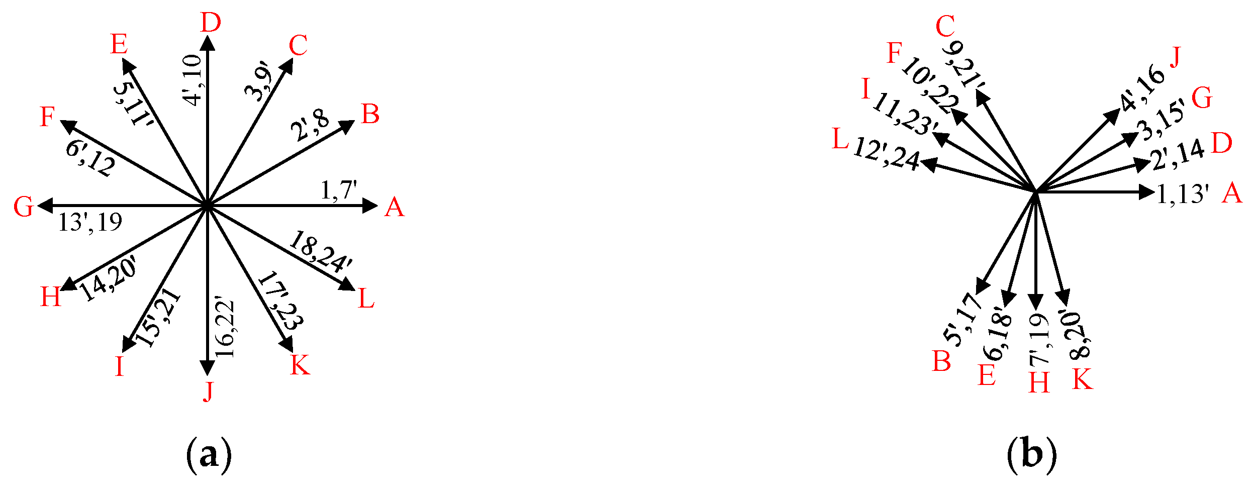
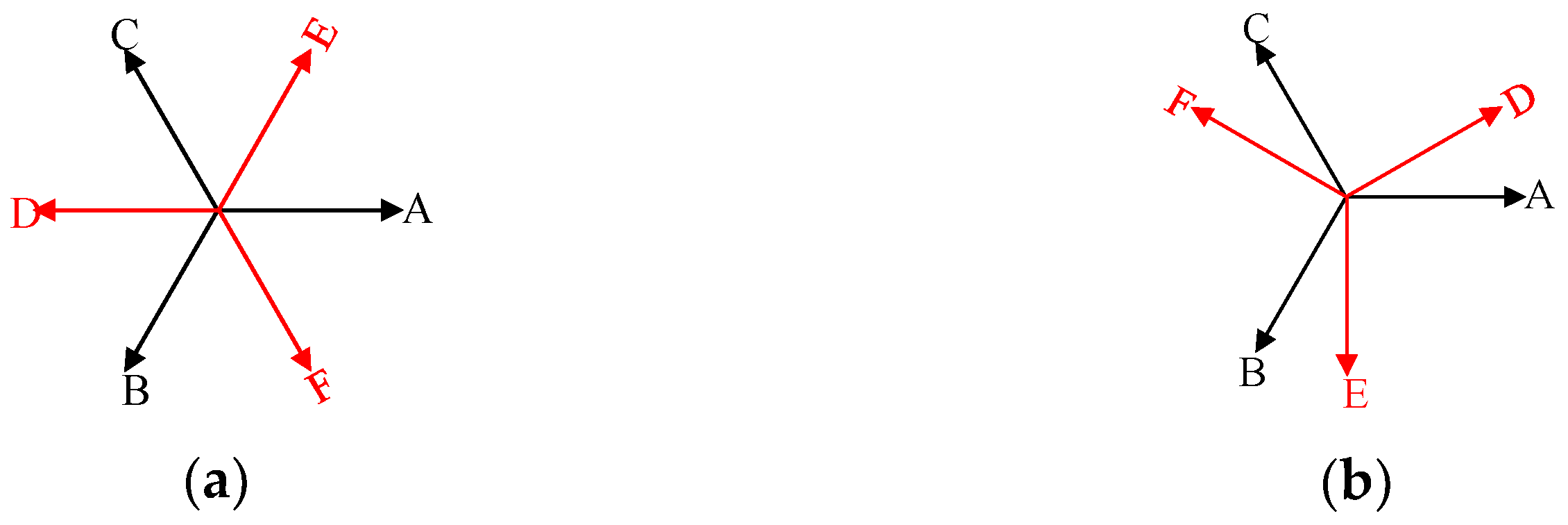
According to different connection styles, the machines with prime phase numbers could be connected into symmetrical and asymmetrical topologies with composite phases. For six-phase conventional FSPM machines, the standard six-phase machine has a symmetrical structure, and the dual three-phase machine has an asymmetrical structure, as shown in Figure 1.
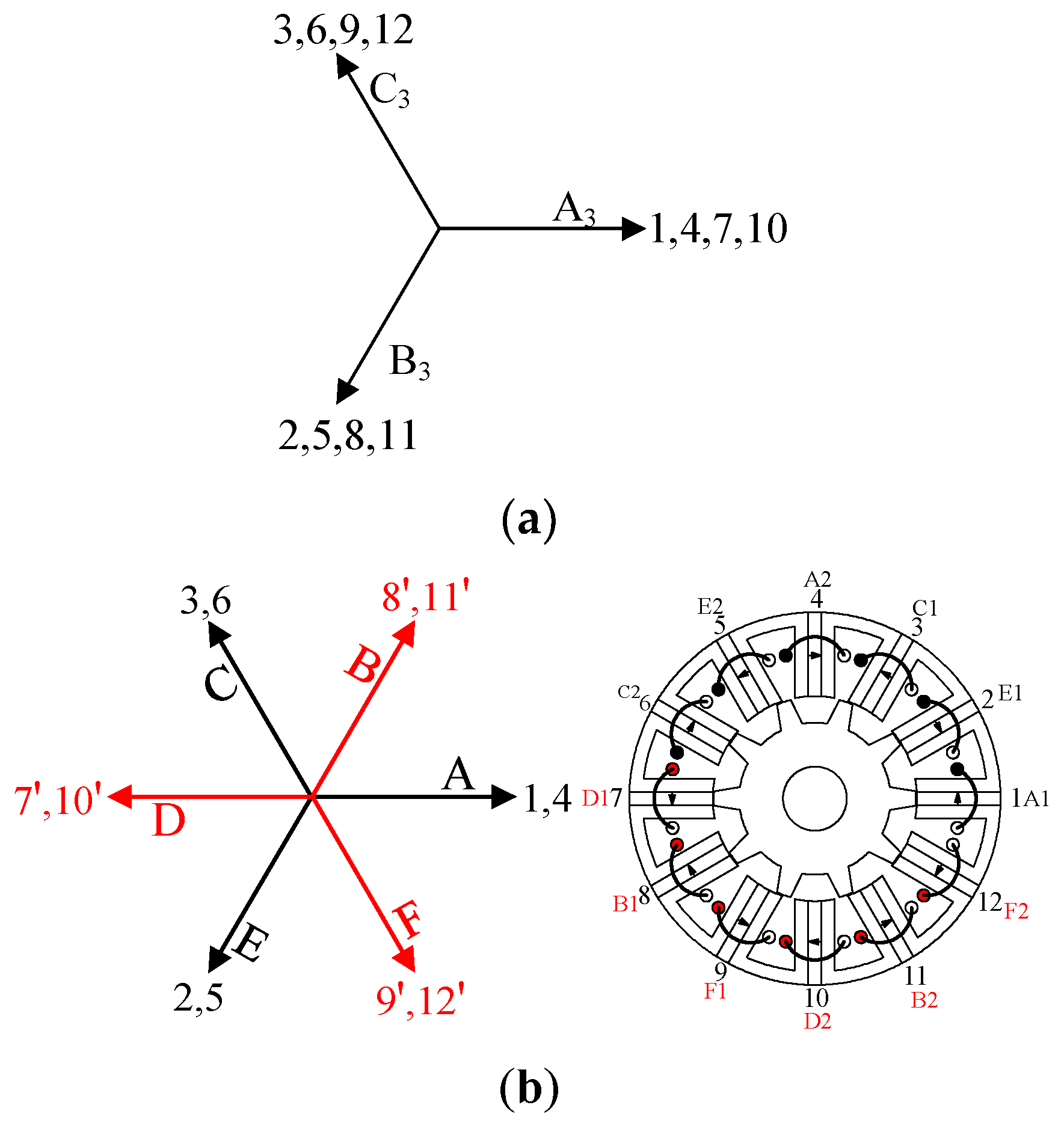
Both the symmetrical and asymmetrical six-phase structures can be obtained by combining three-phase machines. The parameter q′ is the equivalent number of coils per pole per phase, i.e., the number of the consecutively adjacent coils belonging to the same phase, and K is the number of coil pairs having complementarity for the three-phase machines. Similarly, q6′ and K6 are the corresponding parameters of six-phase machines, i.e., the numbers of the consecutively adjacent stator coils belonging to the same phase and coil-pairs having complementarity for six-phase machines. For the three-phase machines with q′ being an odd number and K being an even number, including 12/10, 12/14, 24/20, 24/28, 36/34, and 36/38 topologies, if half of the stator coils connect in opposite polarity, the machines could be connected into a standard six-phase machine. Taking a 12/10 topology shown in Figure 2 as an example, the 12/10 topology shown in Figure 2a is a three-phase structure with q′ = 1 and K = 2, where coils 1, 4, 7, and 10, coils 2, 5, 8, and 11, and coils 3, 6, 9, and 12 belong to phases A3, B3, and C3, respectively (A3, B3, and C3 represent the three phases of three-phase machines). However, the structure can be connected into a standard six-phase 12/10 machine shown in Figure 2b by half coils connected in opposite polarity to A3, B3, and C3. Coils 1 and 4, coils 2 and 5, and coils 3 and 6 remain the same polarity with A3, B3, and C3, composing phases A, E, and C. Coils 7 and 10 are connected in opposite polarity, composing phase D. Similarly, the phases B and F are composed of coils 8 and 11 and coils 9 and 12 in opposite polarity, respectively. It should be noted that the coils connected in reverse are marked with prime indices, such as 7′ in Figure 2b. For the reconnected standard six-phase machine, the number of the consecutively adjacent stator coils belonging to the same phase and coil-pairs having complementarity are both 1, namely, q6′ = 1 and K6 = 1.
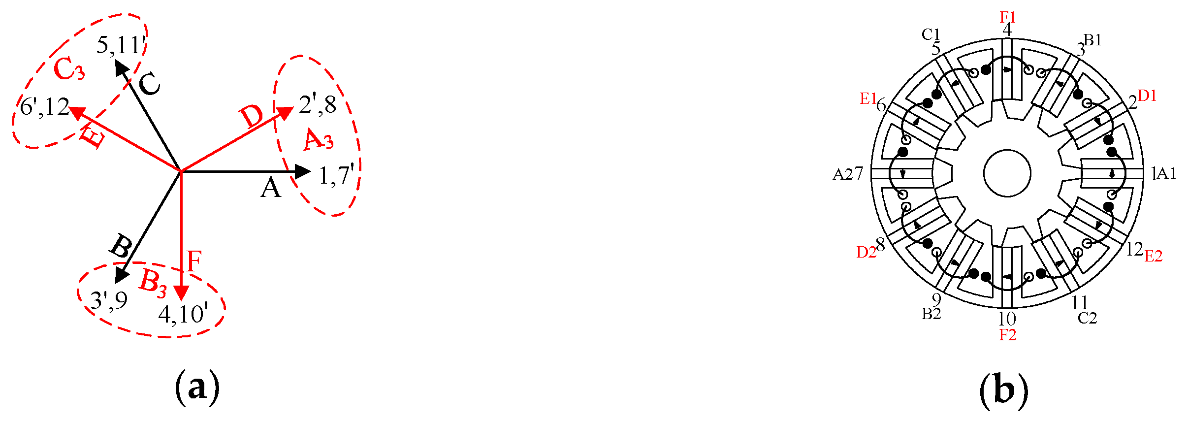
The three-phase machines, with q′ being an even number, such as 12/11, 12/13, 24/22, 24/26, 24/23, 24/25, etc., could be reconnected into dual three-phase machines. Taking the three-phase 12/11 topology (q′ = 2 and K = 1) as an example, phases A3, B3, and C3 are, respectively, composed of coils 1, 2, 7, and 8, coils 3, 4, 9, and 10, and coils 5, 6, 11, and 12, as is illustrated in Figure 3a, where winding-EMF vectors of phases A3, B3, and C3 are, respectively, synthesized from two coil-EMF vectors. Hence, if the coils of the same coil-EMF vector connect into a phase winding, i.e., coils 1 and 7, coils 3 and 9, coils 5 and 11, coils 2 and 8, coils 6 and 12, and coils 4 and 10, respectively, connect into phases A, B, C, D, E, and F; the three-phase 12/11 machine then turns into a dual three-phase 12/11 machine, as is shown in Figure 3, where q6′ = 1 and K6 = 1.
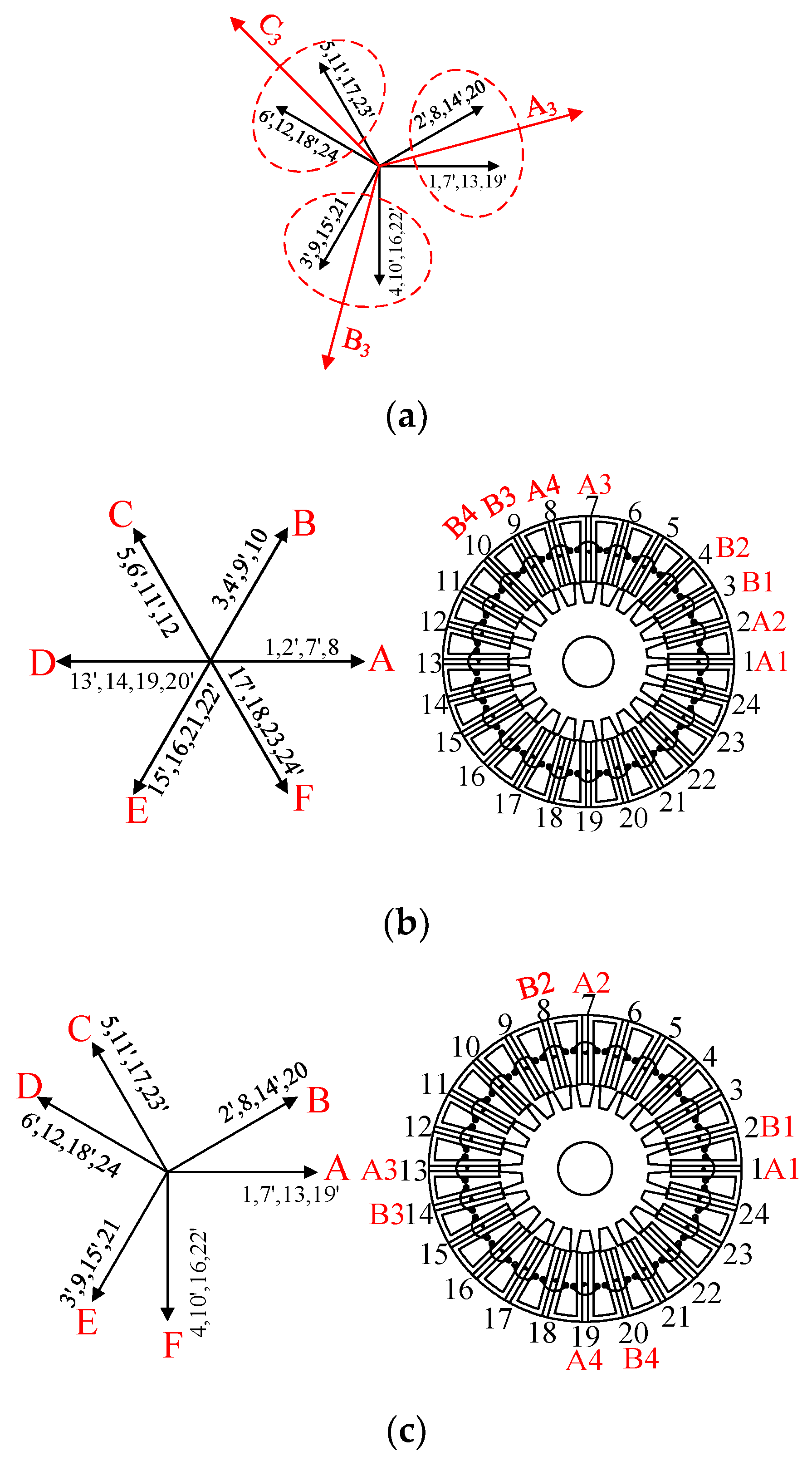
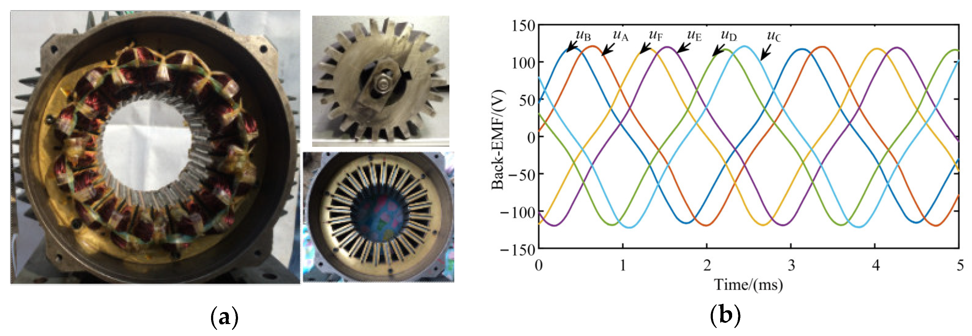
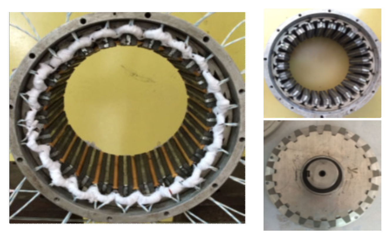
It should be noted that when q′ is an even number, on the one hand, the machines can all be connected into dual three-phase machines, whatever the parameter K is. On the other hand, if K is also an even number, the machines could also be connected to standard six-phase machines. Taking a three-phase 24/22 structure shown in Figure 4a as an example, where q′ = 2 and K = 2, phase A3 consists of coils 1, 2, 7, 8, 13, 14, 19, and 20, and phases B3 and C3 are, respectively, composed of coils 3, 4, 9, 10, 15, 16, 21, and 22 and coils 5, 6, 11, 12, 17, 18, 23, and 24. Winding vectors of phases A3, B3, and C3 are, respectively, synthesized from two coil vectors. If half of the coils in phases A3, B3, and C3 are connected in opposite polarity, it turns out to be a standard six-phase 24/22 machine with q6′ = 2 and K6 = 1 shown in Figure 4b, where the coil connections of phases A and B are exhibited. If the coils of the same coil-EMF vector connect into a phase winding, the three-phase machine changes into a dual three-phase 24/22 machine with q6′ = 1 and K6 = 2, as is presented in Figure 4c, where the coil connection of phases A and B is shown. A dual three-phase 24/22 conventional FSPM prototype has been manufactured and measured, as presented in Figure 5a, and the specific parameters are listed in Table 1. The measured back-EMF waveforms at 1000 r/min are presented in Figure 5b. It can be seen that the back-EMF waveforms are exactly symmetrical.
Based on the above analysis, some conclusions can be drawn. At first, when q′ is an odd number and K is an even number, or q′ is an even number, the corresponding three-phase machines can be reconnected into six-phase machines. Secondly, among the three-phase machines that can be connected into six-phase machines, some machines, where K is an even number, can be reconnected into standard six-phase machines (symmetrical structure); meanwhile, the machines with q′ being an even number can be connected into dual three-phase machines (asymmetrical structure). That is to say, the three-phase combinations with q′ being an even number and K being an even number not only could be connected into standard six-phase structures but also could be connected into dual three-phase structures. Thirdly, if the three-phase structures are connected into six-phase structures, the parameters q′, K, q6′, and K6 must satisfy Equation (2). In addition, for standard six-phase machines, K6 is half of K and q6′ is the same as q′, namely Equation (3), while for dual three-phase machines, K6 is equal to K and q6′ is half of q′, namely Equation (4), i.e., when three-phase machines are connected into six-phase machines, one of the parameters, q′ or K will be reduced to half. The types of six-phase structures and the relationship of parameters q′, K, q6′, and K6 are concluded and listed in Table 2. Taking the combination of three-phase 24/22 where K = 2 and q′ = 2 as an example, this machine could be connected into a standard six-phase machine (K6 = K/2 and q6′ = q′) and can also be connected into a dual three-phase machine (K6 = K and q6′ = q′/2). The specific performance comparisons between the 24/22 standard six-phase machine and the 24/22 dual three-phase machine will be conducted in Section 4. The combinations of stator poles and rotor teeth for six-phase conventional FSPM machines, including symmetrical and asymmetrical structures, are listed in Table A1 in Appendix A.
q 6 K 6 = q K / 2
K 6 = K / 2 q 6 = q
K 6 = K q 6 = q / 2

2.2. Nine-Phase Conventional FSPM Machines

Like six-phase machines, q9′ and K9 are, respectively, the number of the consecutively adjacent stator coils belonging to the same phase and the number of coil-pairs having complementarity for nine-phase machines coils per pole per phase and the number of coil-pairs having complementarity for nine-phase machines. Nine-phase conventional FSPM machines can also be deduced from three-phase machines where q′ is a multiple of three. For example, 18/17, 18/19, 36/34, 36/38 (q= 3), and 36/35, 36/37 (q= 6) three-phase machines can be reconnected to nine-phase machines. Taking an 18/17 structure (q′ = 3, K = 1) as an example, each phase winding of the three-phase 18/17 machine shown in Figure 6a is composed of six coils, covering three coil-EMF vectors, and if the coils with the same coil-EMF vector connect into a phase winding and the coils connect in positive polarity, the three-phase 18/17 machine turns into a standard nine-phase 18/17 machine (symmetrical structure), as is shown in Figure 6b, where q9′ = 1 and K9 = 1. The three-phase machines, being able to be connected to standard nine-phase machines, can also be reconnected into triple three-phase machines. Like the standard nine-phase machine in Figure 6b, if coils 2 and 11, coils 5 and 14, and coils 8 and 17 connect in opposite polarity, the standard nine-phase machine turns into a triple three-phase 18/17 machine with q9′ = 1 and K9 = 1, shown in Figure 6c.
Overall, at first, when q′ is a multiple of three, the corresponding three-phase conventional FSPM machines can be reconnected into nine-phase machines, and in addition, the three-phase topologies cannot only be connected into symmetrical structures (standard nine-phase machines) but also can be connected into asymmetrical structures (triple three-phase machines). Then, if the three-phase structures are connected into nine-phase structures, regardless of symmetrical structures or asymmetrical structures, the parameters q′, K, q9′, and K9 all satisfy Equation (5). The types of nine-phase structures and the relationship of parameters q′, K, q9′, and K9 are listed in Table 3. The specific stator pole and rotor teeth combinations for nine-phase machines are all listed in Table A1 in Appendix A.
K 9 = K q 9 = q / 3
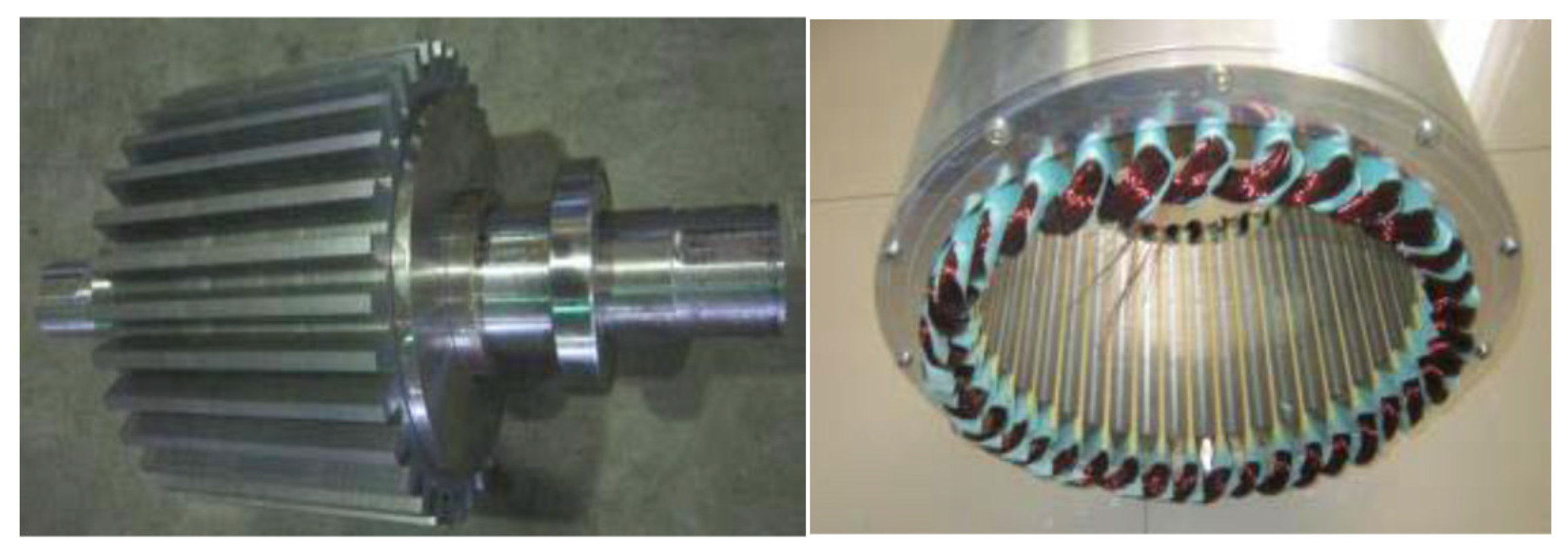
In addition, a standard nine-phase 36/34 conventional FSPM prototype was manufactured and presented in Figure 7, which was detailedly described in the reference [24]. From the measured no-load EMF waveforms at 500 r/min shown in reference [24], it can be seen that the EMF waveforms are exactly symmetrical.

2.3. Twelve-Phase Conventional FSPM Machines

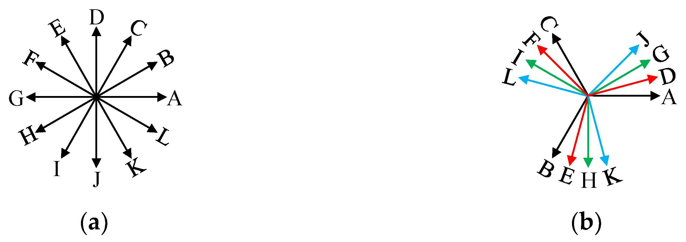
Twelve-phase conventional FSPM machines, including symmetrical structure (standard twelve-phase machine) and asymmetrical structure (four three-phase machines), as shown in Figure 8, can be derived from three-phase structures.
When q′ is an even number and K is also an even number, such as 24/22, 24/26, 48/46, 48/50, etc., the corresponding three-phase structure can be connected into a standard twelve-phase machine. For example, if q′ = 2 and K = 2, the corresponding three-phase 24/22 structure shown in Figure 4a will turn into a standard twelve-phase machine exhibited in Figure 9a if half of the coils change their polarity, and for the obtained machine, the parameters satisfy q12′ = 1 and K12 = 1, where q12′ and K12 represent, respectively, the number of the consecutively adjacent stator coils belonging to the same phase and the number of coil-pairs having complementarity for twelve-phase machines.
All the three-phase structures, where q′ is a multiple of 4 and K is not restricted, could be reconnected into four three-phase machines, shown in Figure 8b, such as 24/23, 24/25, 48/46, 48/50 (q′ = 4), etc. For example, a three-phase 24/23 structure (q′ = 4, K = 1) can be connected into a four three-phase machine shown in Figure 9b, where q12′ = 1 and K12 = 1.
In addition, the machines where q′ is a multiple of 4 and K is an even number, such as 48/46 and 48/50 (q′ = 4, K = 2), can not only be connected into standard twelve-phase machines but also can be connected into four three-phase machines.
Overall, the parameters q′, K, q12′, and K12 must satisfy Equation (6). For standard twelve-phase machines, q12′ and K12 are half of q′ and K, namely Equation (7); meanwhile, for four three-phase machines, q12′ is a quarter of q′ and K12 is equal to K, namely Equation (8). The types of twelve-phase structures and the relationship of parameters q′, K, q12′, and K12 are concluded and listed in Table 4. The combinations of stator poles and rotor teeth for twelve-phase conventional FSPM machines, including symmetrical and asymmetrical structures, are listed in Table A1 in Appendix A.
q 12 K 12 = q K / 4
K 12 = K / 2 q 12 = q / 2
K 12 = K q 12 = q / 4
A standard twelve-phase 24/22 FSPM prototype was manufactured and presented in Figure 10, which was described in the reference [25]. From the measured no-load EMF waveforms at 500 r/min shown in reference [25], it can be seen that the EMF waveforms are exactly symmetrical.

2.4. Four-Phase Conventional FSPM Machines

Similar to six-phase machines deduced from three-phase machines, four-phase machines could be deduced from two-phase structures.
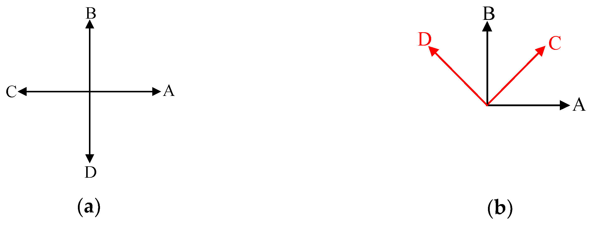
When K is an even number, the corresponding machines, such as 8/6, 8/10, 16/12, 16/20, 24/18, 24/30, 24/22, 24/26, etc., can be connected into standard four-phase machines (symmetrical structure) as is shown in Figure 11a by half of the coils connecting in opposite polarity, such as the standard six-phase topologies.
All the two-phase machines, where q′ is an even number and K is not restricted, such as 8/7, 8/9, 16/14, 16/18, 24/21, 24/27, 32/28, and 32/36, etc., could be reconnected into dual two-phase machines (asymmetrical structure) shown in Figure 11b, such as the dual three-phase topologies. In addition, the machines where q′ and K are all even numbers, such as 16/14, 16/18 (q′ = 2, K = 2), 32/28, and 32/36 (q′ = 2, K = 4), can be connected into standard four-phase machines and also can be connected into dual two-phase machines.
q4′ and K4, respectively, represent the number of the consecutively adjacent stator coils belonging to the same phase and the number of coil-pairs having complementarity for four-phase machines. Parameters q′, K, q4′, and K4 must satisfy Equation (9). For standard four-phase machines, they satisfy Equation (10); meanwhile, for dual two-phase machines, they satisfy Equation (11). The types of four-phase structures and the relationship of parameters q′, K, q4′, and K4 are concluded and listed in Table 5. The specific combinations of stator and rotor poles for four-phase conventional FSPM machines, including symmetrical and asymmetrical structures, are listed in Table A1 in Appendix A.
q 4 K 4 = q K / 2
K 4 = K / 2 q 4 = q
K 4 = K q 4 = q / 2

3. Winding Factors

Winding factors include the distribution factor and pitch factor. The distribution factor kd can be given [26,27]:
k d = sin ( Q v α / 2 ) Q sin ( v α / 2 )
where Q is the number of least EMF vectors per phase, α is the angle between two adjacent coil-EMF vectors, and v is the order of the harmonic. The parameter α is given in Equation (13), where for prime phase machines, m′ is the phase number, and for composite phase machines, m′ is the phase number of the corresponding prime phase machines, which is given in Equation (14).
α = 2 π 2 m q = π m q
m = m P r i m e   p h a s e 2 F o u r - p h a s e 3 S i x - , n i n e - , t w e l v e - p h a s e
The parameter Q is equal to qm′, where qm′ is the number of the consecutively adjacent stator coils belonging to the same phase for m-phase machines with composite phase numbers, which is shown in Equation (15). Finally, the distribution factor kd is expressed as Equation (16).
Q = q m = q p r i m e   p h a s e q 4 f o u r - p h a s e q 6 s i x - p h a s e q 9 n i n e - p h a s e q 12 t w e l v e - p h a s e = q p r i m e   p h a s e q s t a n d a r d   f o u r   p h a s e q / 2 d u a l   t w o - p h a s e q s t a n d a r d   s i x   p h a s e q / 2 d u a l   t h r e e - p h a s e q / 3 n i n e   p h a s e q / 2 s t a n d a r d   t w e l v e - p h a s e q / 4 f o u r   t h r e e - p h a s e
k d = sin ( Q v π / 2 m q ) Q sin ( v π / 2 m q ) = sin ( q m v π / 2 m q ) q m sin ( v π / 2 m q )
The pitch factor, kp can be calculated by Equation (17):
k p = cos θ c 2 = cos ( π v K P s ) = cos ( π v 2 m q )
where parameter K is the number of complementary coil-pairs of corresponding prime phase machines, which can be easily obtained. Taking a standard six-phase 12/10 (q6′= 1, K6 = 2) as an example, the corresponding prime phase machine is the three-phase 12/10 machine (q′ = 1, K = 2); hence, the parameter K in Equation (17) is 2.
Therefore, the winding factor kw can be expressed by Equation (18).
k w = k d k p = sin ( q m v π / 2 m q ) q m sin ( v π / 2 m q ) cos ( π v 2 m q )
The fundamental winding factors of the four, six, nine, and twelve-phase FSPM machines with different stator-rotor combinations, including symmetrical and asymmetrical structures, are calculated and listed in Appendix A.

4. Comparisons Between Two Six-Phase Machines

Based on the foregoing analysis, it is known that some machines with prime phase numbers can be connected into symmetrical structures and can also be connected into asymmetrical structures. Taking a 24/22 structure as an example, a standard six-phase 24/22 machine and a dual three-phase 24/22 machine are derived from a three-phase 24/22 machine, shown in Figure 4. Two six-phase machines have identical configurations, but for winding connections, the specific parameters are listed in Table 1. In this section, the electromagnetic performances in terms of back-EMFs, torques, cogging torques, and inductance waveforms are compared between the two types of six-phase machines using FEA, and the solution method used was the ICCG method.
The fundamental and the third harmonic winding factors of two 24/22 six-phase machines are listed in Table 6 and Table 7, where it can be seen that the fundamental and the third harmonic winding factors of the dual three-phase one are both greater than those of the standard six-phase one. The FEA-simulated phase EMF waveforms of the standard six-phase and dual three-phase 24/22 FSPM machines are shown in Figure 12. The EMFs are both symmetrical, confirming the 24/22 combination is suitable for a six-phase machine. Then the FFT results of both machines are shown in Figure 12b, where it can be seen that the even-order harmonics are very small, and the main harmonics include the 3rd and 5th order harmonics. The magnitudes of fundamental and 3rd harmonic EMFs of the dual three-phase machine are higher than those of the standard six-phase machine, since the fundamental and 3rd harmonic winding factors of the dual three-phase 24/22 machine (0.966, 0.707) are higher than those of the standard six-phase 24/22 machine (0.933, 0.5).
Due to the doubly salient structure and PMs in FSPM machines, there must be cogging torques. It can be seen from Figure 13 that the cogging torques of standard six-phase and dual three-phase 24/22 machines are identical but for a phase shift, due to the identical stators and rotors of the two six-phase machines.
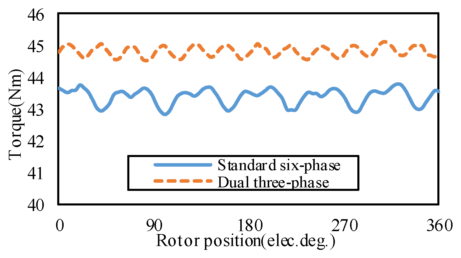
Figure 14 shows the FEA-simulated electromagnetic torque waveforms of two six-phase 24/22 FSPM machines with the rated phase current, namely Ip = IN = 9.5 A, under id = 0 control. Both machines can achieve smooth electromagnetic torques; nevertheless, for the dual three-phase machine, the average torque is 3.4% greater, and the torque ripple is smaller.
The FEA-simulated self-inductances of phase A and the mutual inductances of phases B, C, D, E, and F to phase A in two six-phase 24/22 machines, which are calculated under the condition of phase current of 0.1 A, are shown in Figure 15. For the standard six-phase machine presented in Figure 15a, the self-inductance LAA changes between 2.7 and 3.6 mH, and all the mutual inductances are far lower. The mutual inductances LBA, LCA, and LFA are, respectively, 11%, 5.4%, and 5.6% of the self-inductance LAA, while the mutual inductances LDA and LEA only occupy 0.05% and 0.1%, respectively. Therefore, the mutual inductances are negligible. Figure 15b presents that for the dual three-phase structure, the self-inductance LAA is changing between 2 and 2.7 mH, which is lower than that of the standard six-phase machine. The mutual inductances LBA and LDA cannot be ignored, for both account for 37% of LAA, which is considerable. The other mutual inductances, LCA, LEA, and LFA, can be ignored since they only occupy 3.6%, 3.6%, and 0.0006%, respectively. It should be noted that when the magnetic field of the iron core is not saturated, the inductances are not affected by the phase current, that is, the inductances do not change with the change of current; when the iron core is magnetically saturated, the degree of magnetic saturation is affected by the current, so the inductance will change with the change of current. This paper only compares the inductances of two machines when the magnetic field is not saturated.
Through the above performance combinations between the two six-phase 24/22 FSPM machines, namely the standard six-phase and dual three-phase structures, we draw the following conclusions. Firstly, back-EMF waveforms of both machines are exactly symmetrical, and the magnitude of the fundamental EMF of dual three-phase machines is higher than that of standard six-phase machines, since the winding factor of the dual three-phase 24/22 machine is higher. Secondly, the electromagnetic torque of both machines is sufficiently large, with the dual three-phase machine being 3.4% greater than the standard six-phase machine. Finally, the sufficiently large and symmetrical back-EMFs and the sufficiently large electromagnetic torque confirm the correctness of the stator poles and rotor teeth combinations of six-phase machines.

5. Conclusions

In this paper, the optimal stator-rotor combinations of conventional FSPM machines with composite phases are derived from the corresponding machines with prime phases by changing the parameters of q′ or K. Taking composite phase machines, such as four-phase, six-phase, nine-phase, and twelve-phase machines as examples, a detailed analysis is conducted on how the optimal stator-rotor combinations of composite phase machines are derived from the optimal stator-rotor combinations of the corresponding prime phase machines.
Secondly, for the machines with composite phase numbers, both the symmetrical and asymmetrical structures have been researched. By changing the parameters of q′ or K, the machines with prime phases can be connected into symmetrical or asymmetrical structures based on different connection styles. Then, the winding factor of the conventional FSPM machines with composite phases is calculated.
Finally, taking a three-phase 24/22 conventional FSPM machine as an example, the machine is connected to a standard six-phase 24/22 machine and a dual three-phase 24/22 machine. The sufficiently large and symmetrical back-EMFs and sufficiently large electromagnetic torque confirm the correctness of the proposed method for determining the optimal stator-rotor combinations of the composite phase machines.

Author Contributions

Conceptualization, L.L. and Y.L.; Methodology, Y.L. and G.Z.; Investigation, L.L.; Resources, W.H.; Data curation, Y.D.; Writing—original draft, Y.L.; Writing—review and editing, G.Z.; Supervision, W.H., L.L., and Y.L. contributed equally to this work and should be considered co-first authors. All authors have read and agreed to the published version of the manuscript.

Funding

This work was supported in part by the Shenzhen Science and Technology Program under Project KJZD20240903103800002, the National Natural Science Foundation of China under Projects 52377060.

Data Availability Statement

Due to the nature of this research, participants of this study did not agree for their data to be shared publicly, so supporting data is not available.

Conflicts of Interest

The authors declare no conflicts of interest.

Abbreviations

The following abbreviations and symbols are used in this manuscript:
FSPMflux-switching permanent magnet
EMFelectro-motive-force
NCPPnumber of coils per pole per phase
ENCPPequivalent number of coils per pole per phase
FSflux-switching
psnumber of stator poles
prnumber of rotor teeth
pscnumber of stator coils
Knumber of complementary coil pairs (for the fundamental machine)
Knnumber of complementary coil pairs (for an n-phase machine)
qequivalent number of coils per pole per phase (for the fundamental machine)
qnequivalent number of coils per pole per phase (for an n-phase machine)
kdwinding distribution factor
kpwinding pitch factor
kwwinding factor
Qnumber of the least EMF vectors per phase
αangle between two adjacent coil-EMF vectors
vorder of harmonic
mphase number
mphase number of the fundamental prime phase machine from which a composite phase machine is derived
Ncnumber of coil turns
Ipphase current (rms)
INrated phase current (rms)
idd-axis current
Linductance of the phase winding
Note: The subscript n denotes the phase number (e.g., n = 6 for a six-phase machine, n = 9 for a nine-phase machine, n = 4 for a four-phase machine).

Appendix A

The stator-rotor combinations of conventional FSPM machines with composite phase numbers and the corresponding winding factors are listed in Table A1.
Table A1. Stator and rotor pole combinations of conventional FSPM machines with composite phase numbers and winding factors: (a-1) four-phase (standard four-phase), (a-2) four-phase (dual two-phase), (b-1) six-phase (standard six-phase), (b-2) six-phase (dual three-phase), (c) nine-phase, (d-1) twelve-phase (standard twelve-phase), (d-2) twelve-phase (four three-phase).
(a-1)
qKpsc = ps = 2Kmqpr = ps ± Kq4K4kdkpkw
12861110.7070.707
10
416122
20
221614210.9240.9240.854
18
432282
36
322422310.9110.9660.880
26
423230410.9060.9810.889
34
(a-2)
qKpsc = ps = 2Kmqpr = ps ± Kq4K4kdkpkw
21871110.9240.924
9
216142
18
324213
27
432284
36
411615210.9810.9810.962
17
232302
34
(b-1)
qKpsc = ps = 2Kmqpr = ps ± Kq6K6kdkpkw
1212101110.8660.866
14
424202
28
222422210.9660.9660.933
26
448442
52
323634310.9600.9850.945
38
472682
76
424846410.9580.9910.950
50
496922
100
(b-2)
2112111110.9660.966
13
224222
26
336333
39
448444
52
412423210.9910.9910.983
25
248462
50
372693
75
496924
100
(c)
qKpsc = ps = 2Kmqpr= ps± Kq9K9kdkpkw
311817111 0.9850.985
19
236342
38
354513
57
(d-1)
qKpsc = ps = 2Kmqpr = ps± Kq12K12kdkpkw
2224221110.9660.966
26
448442
52
424846210.9910.9910.983
50
496922
100
(d-2)
4124231110.9910.991
25
248462
50
372693
75
496924
100

References

  1. Rauch, S.E.; Johnson, L.J. Design Principles of Flux-Switch Alternators [Includes Discussion]. Trans. Am. Inst. Electr. Eng. Part III Power Appar. Syst. 1955, 74, 1261–1268. [Google Scholar] [CrossRef]
  2. Hoang, E.; Ahmed, H.B.; Lucidarme, J. Switching Flux Permanent Magnet Polyphased Synchronous Machines. In EPE 97; LESIR: Cachan, France, 1997. [Google Scholar]
  3. Liao, J.; Chen, Q.; Xu, G.; Liu, G.; Liu, Z.; Zhao, W.; Mei, C. Stator Core Loss Suppression of a Rotor Flux-Switching Permanent Magnet Machine by Reconfiguring Rotor Permeance. IEEE Trans. Transp. Electrif. 2025, 11, 2380–2390. [Google Scholar] [CrossRef]
  4. Qiao, Z.; Zhang, Y.; Luo, J.; Fu, W.; Bi, Y.; Huang, J. Huang Design and Analysis of a Consequent-Pole Flux Switching Permanent Magnet Machine With Flux-Concentrated Magnet for Torque Enhancement. IEEE Trans. Energy Convers. 2024, 39, 2468–2479. [Google Scholar] [CrossRef]
  5. Zhang, Q.; Xu, L.; Zhu, X.; Fan, W.; Zhang, C. Flux Regulation Capability Design and Comparative Analysis of Hybrid Excited Axial Flux Switching PM Motors with Different Winding Arrangements. IEEE Trans. Ind. Appl. 2025, 61, 6225–6235. [Google Scholar] [CrossRef]
  6. Wang, D.; Xu, G.; Wang, B.; Wang, X.; Li, Z.; Wang, X. A New Hybrid Excitation Flux Switching Motor Using Low Cost Ferrites with Flux Regulation Capability. IEEE Trans. Energy Convers. 2025, 40, 382–393. [Google Scholar] [CrossRef]
  7. Ozmen, T.; Ergun, B.E.; Gulbahce, M.O.; Onat, N. Rare-Earth Magnet Free Flux-Switching Generator for Wind Turbines in Micro-Grids: A Review. CES Trans. Electr. Mach. Syst. 2024, 8, 295–309. [Google Scholar] [CrossRef]
  8. Zhu, X.; Xiang, Z.; Zhang, C.; Quan, L.; Du, Y.; Gu, W. Co-Reduction of Torque Ripple for Outer Rotor Flux-Switching PM Motor Using Systematic Multi-Level Design and Control Schemes. IEEE Trans. Ind. Electron. 2017, 64, 1102–1112. [Google Scholar] [CrossRef]
  9. Meng, Y.; Fang, S.; Zhu, Y.; Chen, H.; Zhong, Y.; Qin, L. Surrogate-Model-Based Multilevel Optimization Design and Analysis of a New Flux Switching Machine with Double-Sided PM Excitation. IEEE Trans. Transp. Electrif. 2024, 10, 10136–10146. [Google Scholar] [CrossRef]
  10. Liao, J.; Chen, Q.; Xu, G.; Liu, G.; Liu, Z.; Mei, C. Back EMF Harmonics Suppression of a Rotor Permanent Magnet Flux-Switching Motor Through Air-Gap Harmonic Design. IEEE Trans. Ind. Appl. 2025, 61, 3637–3647. [Google Scholar] [CrossRef]
  11. Mamashli, M.; Jamil, M. Enhanced Dynamic Control for Flux-Switching Permanent Magnet Machines Using Integrated Model Predictive Current Control and Sliding Mode Control. Energies 2025, 18, 1061. [Google Scholar] [CrossRef]
  12. Zhang, Z.; Guo, C. Model-Free Speed Control of Single-Phase Flux Switching Motor with an Asymmetrical Rotor. CES Trans. Electr. Mach. Syst. 2024, 8, 255–263. [Google Scholar] [CrossRef]
  13. Yi, J.; Wu, L.; Lu, Y.; Qi, Z.; Zheng, W.; Zheng, T. Fault-Tolerant Operation for Single-Phase Open Circuit of Dual-Armature Flux-Switching Permanent Magnet Machine by Connecting Neutral Points. IEEE Trans. Transp. Electrif. 2025, 11, 2952–2964. [Google Scholar] [CrossRef]
  14. Hussain, S.; Khan, F.; Ullah, W.; Ullah, B.; Khan, B. Optimization and Experimentation of Fault-Tolerant Field Excited Linear Flux Switching Machine with Concentrated and Toroidal Windings for Rail Transportation System. IEEE Trans. Ind. Appl. 2023, 59, 1361–1371. [Google Scholar] [CrossRef]
  15. Fang, Y.; Ji, J.; Zhao, W. Modeling of Fault-tolerant Flux-switching Permanent-magnet Machines for Predicting Magnetic and Armature Reaction Fields. CES Trans. Electr. Mach. Syst. 2022, 6, 413–421. [Google Scholar] [CrossRef]
  16. Tavares, R.B.; Goltz, E.C.; Eckert, P.R.; Pereira, L.A. Torque Assessment of Multiphase AFPM Machines with Experimental Validation for YASA Topology. IEEE Trans. Energy Convers. 2023, 38, 111–121. [Google Scholar] [CrossRef]
  17. Xue, X.; Zhao, W.; Zhu, J.; Liu, G.; Zhu, X.; Cheng, M. Design of Five-Phase Modular Flux-Switching Permanent-Magnet Machines for High Reliability Applications. IEEE Trans. Magn. 2013, 49, 3941–3944. [Google Scholar] [CrossRef]
  18. Abdel-Khalik, A.S.; Massoud, A.M.; Ahmed, S. Application of Standard Three-Phase Stator Frames in Prime Phase Order Multiphase Machine Construction. IEEE Trans. Ind. Electron. 2019, 66, 2506–2517. [Google Scholar] [CrossRef]
  19. Bianchi, N.; Pré, M.D. Use of the star of slots in designing fractional-slot single-layer synchronous motors. IEE Proc.-Electr. Power Appl. 2006, 153, 459–466. [Google Scholar] [CrossRef]
  20. Gao, C.; Jia, X.; Zhao, G.; Hua, W.; Cheng, M. General Principles of Combinations of Stator Poles and Rotor Teeth for Conventional Flux-Switching Brushless Machines with Prime Phase Numbers. Energies 2025, 18, 3322. [Google Scholar] [CrossRef]
  21. Thomas, A.S.; Zhu, Z.Q.; Owen, R.L.; Jewell, G.W.; Howe, D. Multiphase Flux-Switching Permanent-Magnet Brushless Machine for Aerospace Application. IEEE Trans. Ind. Appl. 2009, 45, 1971–1981. [Google Scholar] [CrossRef]
  22. Zhao, W.; Pan, X.; Ji, J.; Xu, L.; Zheng, J. Analysis of PM Eddy Current Loss in Four-Phase Fault-Tolerant Flux-Switching Permanent-Magnet Machines by Air-Gap Magnetic Field Modulation Theory. IEEE Trans. Ind. Electron. 2019, 67, 5369–5378. [Google Scholar] [CrossRef]
  23. Zhang, G.; Hua, W.; Cheng, M.; Liao, J. Design and Comparison of Two Six-Phase Hybrid-Excited Flux-Switching Machines for EV/HEV Applications. IEEE Trans. Ind. Electron. 2016, 63, 481–493. [Google Scholar] [CrossRef]
  24. Li, F.; Hua, W.; Tong, M.; Zhao, G.; Cheng, M. Nine-Phase Flux-Switching Permanent Magnet Brushless Machine for Low-Speed and High-Torque Applications. IEEE Trans. Magn. 2015, 51, 8700204. [Google Scholar]
  25. Shao, L.; Hua, W.; Dai, N.; Tong, M.; Cheng, M. Mathematical Modeling of a 12-Phase Flux-Switching Permanent-Magnet Machine for Wind Power Generation. IEEE Trans. Ind. Electron. 2016, 63, 504–516. [Google Scholar] [CrossRef]
  26. Chen, J.T.; Zhu, Z.Q. Winding Configurations and Optimal Stator and Rotor Pole Combination of Flux-Switching PM Brushless AC Machines. IEEE Trans. Energy Convers. 2010, 25, 293–302. [Google Scholar] [CrossRef]
  27. Bianchi, N.; Pr’e, M.D.; Alberti, L.; Fornasiero, E. Theory and Design of Fractional-Slot PM Machines; CLEUP: Padova, Italy, 2007. [Google Scholar]
Figure 1. Six-phase machines. (a) Standard six-phase, (b) dual three-phase.
Electronics 14 03405 g001
Figure 2. The 12/10 FSPM machine. (a) Coil-EMF vectors for a three-phase machine, (b) coil-EMF vectors and coil connection for a standard six-phase machine.
Electronics 14 03405 g002
Figure 3. Dual three-phase 12/11 FSPM machine. (a) Coil-EMF vectors, (b) coils connection.
Electronics 14 03405 g003
Figure 4. 24/22 FSPM machines. (a) Coil-EMF vectors of a three-phase 24/22 machine, (b) standard six-phase machine, (c) dual three-phase machine.
Electronics 14 03405 g004
Figure 5. Dual three-phase 24/22 FSPM machine. (a) Dual three-phase 24/22 prototype, (b) the experimentally measured back-EMF waveform.
Electronics 14 03405 g005
Figure 6. Coil-EMF vectors of 18/17 machines. (a) Three-phase, (b) Standard nine-phase, (c) Triple three-phase.
Electronics 14 03405 g006
Figure 7. Nine-phase 36/34 prototype [24].
Electronics 14 03405 g007
Figure 8. Twelve-phase structures. (a) Standard twelve-phase, (b) four three-phase.
Electronics 14 03405 g008
Figure 9. Coil-EMF vectors of twelve-phase machines (a) Standard twelve-phase 24/22 topology, (b) Four three-phase 24/23 topology.
Electronics 14 03405 g009
Figure 10. Standard twelve-phase 24/22 FSPM prototype [25].
Electronics 14 03405 g010
Figure 11. Four-phase machines. (a) Standard four-phase, (b) dual two-phase.
Electronics 14 03405 g011
Figure 12. The FEA-simulated phase back-EMF waveforms and FFT results. (a) Phase back-EMF waveforms, (b) FFT results.
Electronics 14 03405 g012
Figure 13. The FEA-simulated cogging torques of two six-phase 24/22 FSPM machines.
Electronics 14 03405 g013
Figure 14. The FEA-simulated electromagnetic torques of two six-phase 24/22 FSPM machines.
Electronics 14 03405 g014
Figure 15. The FEA-simulated inductances of two six-phase 24/22 FSPM machines. (a) Standard six-phase 24/22 machine, (b) Dual three-phase 24/22 machine.
Electronics 14 03405 g015
Table 1. Key parameters of the dual three-phase 24/22 FSPM prototype.
ItemsDimensions and Parameters
Stator-rotor combination 24/22
Measured speed1000 r/min
Rated speed1500 r/min
Magnet typeNdFeB N35
Iron core50 WW470
Stator outer diameter226 mm
Split ratio0.58
Active stack length75 mm
Air-gap length0.9 mm
Rotor inner diameter22 mm
Number of coil turns, Nc28
Rated phase current (rms), IN9.5 A
Table 2. Six-phase machines derived from three-phase structures.
qKTypes of the Six-Phaseq6K6
oddevenstandard six-phaseqK/2
evenevenstandard six-phaseqK/2
dual three-phaseq′/2K
odddual three-phaseq′/2K
Table 3. Nine-phase machines and the corresponding three-phase structures.
qKTypes of the Nine-Phaseq9K9
multiple of 3allstandard nine-phaseq′/3K
triple three-phase
Table 4. Twelve-phase machines and the corresponding three-phase structures.
qKTypes of Twelve-Phaseq12K12
even (not a multiple of 4)evenstandard twelve-phaseq′/2K/2
multiple of 4evenstandard twelve-phaseq′/2K/2
four three-phaseq′/4K
oddfour three-phaseq′/4K
Table 5. Four-phase machines and the corresponding two-phase structures.
qKTypes of Four-Phaseq4K4
oddevenstandard four-phaseqK/2
evenevenstandard four-phaseqK/2
dual two-phaseq′/2K
odddual two-phaseq′/2K
Table 6. The fundamental winding factors of two 24/22 six-phase machines.
qKpsc/prTypeq6K6kdkpkw
2224/22Standard six-phase210.9660.9660.933
24/22Dual six-phase1210.9660.966
Table 7. The third harmonic winding factors of two 24/22 six-phase machines.
qKpsc/prTypeq6K6kd(3)kp(3)kw(3)
2224/22Standard six-phase210.7070.7070.5
24/22Dual six-phase1210.7070.707
Disclaimer/Publisher’s Note: The statements, opinions and data contained in all publications are solely those of the individual author(s) and contributor(s) and not of MDPI and/or the editor(s). MDPI and/or the editor(s) disclaim responsibility for any injury to people or property resulting from any ideas, methods, instructions or products referred to in the content.