Article

Design of a Brushless DC Motor Drive System Controller Integrating the Zebra Optimization Algorithm and Sliding Mode Theory

Department of Electrical Engineering, National Chin-Yi University of Technology, Taichung 41170, Taiwan
*
Author to whom correspondence should be addressed.
Electronics 2025, 14(17), 3353; https://doi.org/10.3390/electronics14173353
Submission received: 10 June 2025 / Revised: 17 August 2025 / Accepted: 19 August 2025 / Published: 22 August 2025

Abstract

This paper presents a novel speed controller design for a brushless DC motor (BLDCM) operating under field-oriented control (FOC). The proposed speed controller is developed by integrating the zebra optimization algorithm (ZOA) with sliding mode theory (SMT). In this approach, the parameter ranges of the sliding mode dynamic trajectory control gain, exponential reaching gain, and constant speed reaching gain—three key components of the exponential reaching law-based sliding mode controller (ERLSMC)—are defined as the research space for the ZOA. The feedback speed error and its rate of change are used as features to calculate the fitness value. Subsequently, the fitness value computed by the algorithm is compared with the current best fitness value to determine the optimal position coordinates. These coordinates correspond to the optimal set of gain parameters for the sliding mode speed controller. During the operation of the BLDCM, these optimized parameters are applied to the controller in real time. This enables the system to adjust the three gain parameters dynamically under different operating conditions, thereby reducing the overshoot commonly induced by the ERLSMC. As a result, the speed response of the BLDCM drive system can more accurately and rapidly track the speed command. Therefore, the proposed control strategy is not only characterized by a small number of parameters and ease of tuning, but also does not require large datasets for training, making it highly practical and easy to implement. Finally, the proposed control strategy is simulated using Matlab/Simulink (2024b version) and applied to the BLDCM drive system for experimental testing. Its performance is compared against three types of sliding mode controllers employing different reaching laws: the constant speed reaching law, the exponential reaching law, and the exponential reaching law combined with extension theory (ET). Simulation and experimental results confirm that the proposed novel speed controller outperforms the other three sliding mode controllers based on different reaching laws, both in terms of speed command tracking and load regulation response.

1. Introduction

Brushless DC motors (BLDCMs) [1,2] have been widely used in industrial applications due to their advantages such as high torque, high power-to-weight ratio, high efficiency, and low noise. However, as the requirements for speed response and position control accuracy become increasingly stringent, field-oriented control (FOC) [3] technology is widely adopted in industrial domains to achieve precise speed and position control. Conventional FOC is implemented as a closed-loop system consisting of coordinate transformation, a speed controller, a d-axis current controller, and a q-axis current controller, each realized using proportional-integral (P-I) controllers [4]. However, although traditional P-I controllers are relatively easy to design, they are unable to simultaneously achieve both command tracking and load regulation. Moreover, their control performance tends to degrade significantly when the system is subjected to external disturbances. Different intelligent control strategies also have their own limitations. For instance, although the sliding mode controller (SMC) [5] offers a strong disturbance rejection capability, it fails to simultaneously achieve effective command tracking and load regulation. Among them, the two-degree-of-freedom controller (2DOFC) enhances overall control performance by combining a feedforward controller with a P-I controller. This controller separates command tracking and disturbance rejection by its design, which provides high flexibility and makes it suitable for complex system control; however, the design and tuning of its parameters are relatively challenging. Fuzzy theory-based controllers are widely used across various domains due to their ease of implementation and robust disturbance rejection; however, as they rely on approximation methods, their control performance may fall short in applications requiring high accuracy, such as highly nonlinear systems or those demanding rapid dynamic responses. Although extension theory (ET) [6] enables the flexible adjustment of system parameters to accommodate diverse control requirements, it may lead to system instability when the operating point falls outside the defined neighborhood domain. As for the particle swarm optimization (PSO) algorithm, although it features a simple structure and fast convergence, it is prone to premature convergence, which may prevent it from finding the global optimum. The zebra optimization algorithm (ZOA) [7], by contrast, offers a simple structure, ease of implementation, and an inherent ability to avoid local optima; however, due to its relatively small number of parameters, its control performance is more sensitive to parameter settings compared to other optimization algorithms. To address the aforementioned limitations of existing controllers, hybrid approaches that combine different algorithms have been developed to enhance adaptability and improve control performance. Examples include controllers integrating ET with sliding mode theory (SMT) [8], extendable fuzzy theory with two-degree-of-freedom controllers (EFT2DOFCs) [9], and the particle swarm optimization algorithm combined with P-I controllers (PSOP-IC) [10]. Although extension theory combined with an exponential reaching law-based sliding mode controller (ETERLSMC) can effectively suppress overshoot in exponential reaching law-based sliding mode controllers (ERLSMCs), the parameter adjustment relies on approximation through look-up tables, which may yield inaccurate results when data is limited. Similarly, the EFT2DOFC may exhibit slight oscillations in load regulation response. Furthermore, the PSOP-IC has been shown to perform inadequately in both speed command tracking and load regulation scenarios. Therefore, this study proposes a control approach that integrates the ZOA with sliding mode control to enable the adaptive control of BLDCMs under various operating conditions within the rated speed range. By automatically tuning the three gain parameters of the ERLSMC, the proposed method enhances both the dynamic and steady-state performance of the motor drive system.
The control strategy proposed in this study employs the speed error defined as the difference between the reference speed command and the actual speed of the brushless DC motor as a characteristic feature to compute the current fitness value. This fitness value serves as the optimization objective in the ZOA, which is used to tune three key gain parameters of the ERLSMC: the sliding trajectory gain, the exponential reaching gain, and the constant reaching gain. These three parameters are defined as the three-dimensional survival space for the zebra population. By simulating the foraging behavior and predator avoidance mechanisms inherent in zebra populations, the ZOA iteratively searches for the optimal survival coordinates within this space. These coordinates correspond to the optimal gain values for the ERLSMC. During motor operation, the fitness values of candidate solutions were continuously evaluated, allowing the controller to dynamically output the most appropriate gain parameters in real time. As a result, the proposed control method enhances the speed tracking performance of the BLDC motor drive system across varying operating conditions. In particular, the application of the exponential reaching law significantly mitigates overshooting, thereby improving the transient response and overall dynamic performance of the system.

2. Brushless DC Motor Drive System

The BLDCM utilizes electronic commutation, in which optical encoders or Hall-effect sensors embedded in the rotor shaft [11] are used to detect the rotor’s position in real time. This position feedback is sent to the controller, which in turn adjusts the direction of the current in the stator windings via the inverter, based on the detected rotor position. This mechanism ensures a stable rotating magnetic field to drive the rotor, thereby achieving efficient and accurate commutation.

2.1. Field-Oriented Control Architecture

FOC also known as vector control, aims to simplify the mathematical model [12] of a BLDCM by transforming the voltage and flux equations from a three-phase rotating coordinate system into a two-axis synchronous coordinate system through coordinate transformation [13]. This transformation reduces both computational complexity and the difficulty of controller design. The operational flow begins by decoupling the current signals into voltage signals using P-I controllers, followed by coordinate transformation. Subsequently, space vector pulse width modulation (SVPWM) is employed to control the switching operations of the six power semiconductor devices within the inverter [14]. The motor’s output parameters—such as rotation speed, voltage, and current—are then fed back to the controller. The speed controller processes this feedback to track the speed command and eliminate the steady-state speed error.
In the synchronous rotating ( d , q ) coordinate system, if the rotor of the BLDCM does not contain damper windings and the permanent magnets are mounted on the rotor surface, the permanent magnets can be equivalently modeled as a constant current source. If the angular velocity ω of an arbitrary two-axis rotating reference frame is set equal to the rotor speed, then ω = ω r . In a synchronous motor, the electrical rotor speed is equal to the synchronous speed, leading to ω = ω r = ω e . Furthermore, since the rotor current is responsible for generating the magnetic field, the rotor current can be represented as a constant excitation current, i.e., i r = I r F . Since the permanent magnets of the rotor exist exclusively along the d-axis, they can be modeled as a constant current source I r F on the d-axis. Consequently, the rotor current along the q-axis is zero. Based on this, the magnetic flux can be expressed as shown in Equations (1) and (2).
ϕ d s = L d i d s + L m I r F
ϕ q s = L q i q s
where, ϕ d s and ϕ q s represent the stator flux along the d-axis and q-axis, respectively. The flux linkage generated by the permanent magnets in the stator windings is given by L m I r F = L m i r = ϕ F . Accordingly, the stator voltages can be expressed by Equations (3) and (4).
v d s = R s i d s + L d d i d s d t ω e L q i q s
v q s = R s i q s + L q d i q s d t + ω e L d i d s + ω e ϕ F
where, v d s and v q s are the stator voltages along the d-axis and q-axis, respectively; R s is the stator resistance; i d s and i q s are the stator currents along the d-axis and q-axis; ω e is the electrical angular velocity; and L d and L q are the stator inductances along the d-axis and q-axis, respectively. Since the d-axis aligns with the stator windings while the q-axis aligns with the stator core, the magnetic reluctance along the d-axis is greater than that along the q-axis. As a result, L d > L q .
The motor’s electromagnetic torque and mechanical equation can be expressed as Equations (5) and (6), respectively.
T e     3 2 P 2 [ ϕ F i q s + ( L d L q ) i d s i q s ]
T e = J d ω m d t + B ω m + T L
where, T e is the electromagnetic torque; P is the number of poles; J is the moment of inertia; ω m is the mechanical angular velocity; T L is the load torque; B is the viscous friction coefficient.
If FOC is employed, the direct-axis stator current can be set to zero, thereby allowing Equations (3) through (5) to be simplified into Equations (7) through (9).
v d s = ω e L q i q s
v q s = R s i q s + L q d i q s d t + ω e ϕ F
T e = 3 2 P 2 ϕ F i q s = K t i q s
From the relationship between electromagnetic torque Te and the q-axis stator current in Equation (9), the torque constant K t can be derived, as shown in Equation (10).
K t = 3 2 P 2 ϕ F
By substituting Equation (9) into the mechanical equation of the BLDCM (Equation (6)), Equation (11) can be obtained.
d ω m d t = 1 J K t i q s B ω m T L
In FOC, the d-axis of the two-phase stationary coordinate system is first aligned with the α-axis of the three-phase ( a , b , c ) stationary coordinate system. The three-phase AC currents fed back from the motor are then transformed into two-phase AC currents in the stationary coordinate frame using the Clarke transformation, as shown in Equation (12).
i α i β = 2 3 1 1 / 2 1 / 2 0 3 / 2 3 / 2 i a i b i c
Next, the Park transformation is used to convert the two-phase AC currents in the ( α , β ) stationary frame into DC currents in the ( d , q ) synchronous rotating frame. These are then fed back to the controller. The transformation is described by Equation (13).
i d i q = cos θ sin θ sin θ cos θ i α i β
The Inverse Park transformation converts the decoupled ( d , q ) control voltages in the synchronous rotating frame back into AC voltages in the ( α , β ) stationary coordinate frame, as shown in Equation (14).
v α v β = cos θ sin θ sin θ cos θ v d v q
Subsequently, the voltages v α and v β obtained from the transformation are used for SVPWM. These two-phase ( α , β ) AC voltages are then converted into three-phase ( a , b , c ) AC voltages through an internal Inverse Clarke Transformation. This conversion enables the control of the inverter’s switching states. The transformation equations are given in Equation (15).
v a v b v c = 1 0 1 / 2 3 / 2 1 / 2 3 / 2 v α v β
Through the above steps, closed-loop control of the BLDCM drive system can be achieved. From the torque and voltage equations, it can be observed that under FOC, the motor torque can be directly regulated by controlling the q-axis current, while the d-axis voltage is dependent only on the q-axis current. This confirms that the proposed control strategy significantly simplifies the control architecture and reduces the system complexity for BLDCM drive systems.

2.2. Proportional-Integral (P-I) Controller

A P-I controller is a type of controller used to regulate the stability and response speed of control systems. Due to its simple structure and ease of tuning, it is widely employed across various applications. In FOC systems for BLDCM drive systems, P-I controllers are typically used to regulate both the speed and current in closed-loop control configurations. In d-q axis current control, the three-phase currents are transformed into the stator currents i d s and i q s in the d-axis and q-axis, respectively. A P-I controller is then used to perform closed-loop control on each of these components, thereby enabling precise regulation of the magnetic field and torque. In general, to maximize motor torque—achieving maximum torque per ampere (MTPA) [15]—the d-axis current i d s is set to zero. The q-axis P-I controller then adjusts the control input based on the error between the actual current i q s and the reference current i q s , thereby enabling precise torque regulation. The reference current i q s is generated by the outer-loop speed P-I controller, which computes the torque current command based on the error between the speed command and the actual speed. Thus, by employing the aforementioned speed loop along with the d-axis and q-axis current loops—each controlled by a dedicated P-I controller—the actual speed of the BLDCM can effectively track the speed command with zero steady-state error.
Although P-I controllers are suitable for most control systems, their performance can degrade in nonlinear systems. They may exhibit delayed or unstable responses under rapid dynamic changes; therefore, in this study, the proposed novel controller is used to replace the P-I controller in the speed control loop, aiming to enhance speed command tracking and load regulation performance. Figure 1 shows the block diagram of the FOC architecture adopted in this paper for the BLDCM drive system.

3. Proposed Drive Control Based on the Novel Algorithm

In conventional FOC, using only a P-I controller in the speed loop makes it difficult to simultaneously achieve both precise speed command tracking and effective load regulation; therefore, in this study, the proposed novel controller is used to replace the P-I controller in the speed control loop. The proposed control architecture integrates the ZOA with a SMC. It utilizes the current speed error and the rate of change in that error to dynamically adjust the gain parameters of the SMC based on the optimization results produced by the ZOA. This approach provides tunable robustness of the controller parameters [16], thereby enhancing the overall performance of speed control.

3.1. Zebra Optimization Algorithm

The ZOA is a novel bio-inspired swarm intelligence optimization method, introduced by Eva Trojovská et al. in 2022 [7,17]. This algorithm is inspired by the natural survival behaviors of zebras in the wild. The core concept of the ZOA is based on mimicking the foraging behavior of zebras as they search for food across vast environments, as well as their defensive behavior in response to different predators. By simulating these behaviors, the algorithm identifies regions with more favorable survival resources—such as food and water—and lower predator threats, thereby determining the optimal location for survival.

3.1.1. Foraging Behavior

In nature, zebras primarily feed on grass, leaves, and fruits; however, when food is scarce, they may consume bark and roots as alternative sources of nutrition. Depending on the quality of the available food, zebras may spend between 60% and 80% of their time grazing. Among the various zebra species, the plains zebra is the most well-known. As a pioneer grazing animal, it typically feeds on taller and less nutritious grasses. This feeding behavior improves the survival chances of other herbivores that rely on more nutritious, low-growing vegetation. Therefore, in the first stage of the ZOA, the member of the population with the best fitness is designated as the pioneer zebra. This pioneer guides the other members to locate optimal positions within the search space. The remaining individuals follow the pioneer zebra to update their positions and continue the search process. Whenever a zebra with better fitness is identified, it replaces the previous pioneer, and the rest of the population begins moving toward the new leader’s position. The initialization values of the algorithm are defined by Equation (16).
X i , j = l b j + r · u b j l b j
where, X i , j represents the position of the i-th zebra in the j-th dimension; l b j and u b j denote the lower and upper bounds of the search space in the j-th dimension, respectively; and r is a random number uniformly distributed in the range [0, 1].
The mathematical representation of the foraging behavior is given by Equations (17) and (18).
X i , j n e w , P 1 = X i , j + r · P Z j I · X i , j
X i = X i new , P 1 , F i n e w , P 1 < F i ; X i , e l s e
In Equation (17), X i , j n e w , P 1 represents the new position of the i-th zebra in the j-th dimension during the first-stage foraging behavior, and P Z j denotes the position of the pioneer zebra in the j-th dimension. The variable I is a randomly selected integer with a value of either 1 or 2. Its purpose is to introduce different magnitudes of movement when individuals update their positions by following the pioneer zebra, thereby increasing the diversity of the population within the search space and enhancing the algorithm’s ability to escape local optima. In Equation (18), X i refers to the current position of the i-th zebra, and X i n e w , P 1 is its new position obtained through the first-stage foraging behavior. F i and F i n e w , P 1 represent the current fitness value of the i-th zebra and the fitness value after the first-stage foraging, respectively.

3.1.2. Defense Behavior

The second phase of the ZOA is the defensive behavior, which is inspired by the zebras’ strategic responses when confronted by predators. This phase is used to update the positions of population members within the search space. Since zebras primarily inhabit grasslands, their main natural predators are lions; however, they also face threats from smaller carnivores such as African wild dogs, cheetahs, and spotted hyenas. Zebras adopt different defense strategies depending on the level of threat posed by the predator. When attacked by lions, zebras typically evade by performing sharp, zigzag maneuvers—known as Z-shaped escape routes. In contrast, when facing smaller predators, zebras exhibit more aggressive and proactive defense strategies. They form protective circles around their young and utilize their distinctive black-and-white stripes to confuse predators, making it difficult for them to distinguish individual targets. This visual effect helps to disorient, intimidate, or even drive away predators. Such strategies are metaphorically embedded in the algorithm to enhance its ability to escape local optima. Assuming both types of predator encounters occur with equal probability, the corresponding behavioral models can be mathematically represented by Equations (19) and (20).
X i , j n e w , P 2 = S 1 : X i , j + R · 2 r - 1 · 1 t T · X i , j , P s 0.5 ; S 2 : X i , j + r · A Z j I · X i , j , e l s e
X i = X i new , P 2 , F i n e w , P 2 < F i ; X i , e l s e
In Equation (19), S 1 and S 2 represent two defensive strategies: an escape strategy adopted when attacked by lions, and an aggressive strategy adopted when another predator targets one of the zebras, respectively. X i n e w , P 2 denotes the new position of the i-th zebra in the j-th dimension during the second-stage defensive behavior. R is a constant set to 0.01, while t and T denote the current iteration number and the maximum number of iterations, respectively. Ps is a uniformly distributed random variable within the range [0, 1]. It is used in the second-stage defensive behavior of the ZOA to randomly determine the type of predator encountered by a zebra, which in turn dictates the selection of the corresponding defensive strategy, and A Z j indicates the position of the attacked zebra in the j-th dimension. Similar to Equation (18), Equation (20) specifies that after updating the positions of all zebras, the individual with the best (i.e., lowest) fitness value among the entire population is selected as the new pioneer zebra. The above steps are then repeated until the maximum number of iterations is reached, and the current best solution is taken as the optimal survival position.

3.2. Sliding Mode Controller

In general, conventional P-I controllers can meet the control performance requirements at most specific operating points. However, because the BLDCM is a highly coupled, nonlinear, multivariable system, it is often subject to parameter variations, load changes, and external disturbances. These factors may compromise the originally designed control performance, making it difficult to satisfy the performance demands of the intended application. To address these issues, various intelligent control strategies have been proposed to replace traditional P-I controllers, or to enhance their robustness and adaptability by integrating them with alternative control methodologies.
Sliding mode control, based on the principle of variable structure control [18], exhibits low dependency on precise motor models. By designing sliding mode dynamic trajectories, the nonlinear dynamics of the system can be transformed into linear dynamics along the sliding surface. This approach offers strong disturbance rejection capabilities and robustness, enabling the system to tolerate model uncertainties and external perturbations effectively. As such, SMCs provide excellent control performance for applications requiring high dynamic responsiveness in BLDCM systems.

3.2.1. State Variable Design

To replace the conventional P-I controller in the speed loop of FOC with a SMC, the control strategy must adopt i d s = 0 . Based on the voltage equations of the BLDC motor in the d-axis and q-axis, given in Equations (3) and (4), Equation (21) can be derived. Assuming an ideal system, where the viscous friction coefficient is negligible, the dynamic equations of the BLDCM described in Equations (9) and (10) can then be simplified into Equation (22).
d i q s d t = 1 L q ( R s i q s P 2 ω m ϕ F + v q s )
d ω m d t = 1 J ( T L + 3 P 4 ϕ F i q s )
In terms of speed tracking control, it is necessary to ensure that the speed difference (i.e., the error) between the commanded rotor speed ω m and the actual feedback speed signal ω m is zero, that is, ω m ω m = 0 , and that the rate of change in the speed difference ω ˙ m is also zero. The controller output is the commanded q-axis current i q s . Based on this, the state variables of the BLDCM system can be defined, as shown in Equation (23).
x 1 = ω m ω m x 2 = x ˙ 1 = ω ˙ m
By differentiating Equations (22) and (23), the rate of change in the state variables can be obtained as expressed in Equation (24).
x ˙ 1 = ω ˙ m = 1 J ( T L 3 P 4 ϕ F i q s ) x ˙ 2 = ω ¨ m = 1 J 3 P 4 ϕ F i ˙ q s
Let D = 1 J 3 P 4 ϕ F , and substitute it into x ˙ 2 in Equation (24) to obtain Equation (25).
x ˙ 2 = ω ¨ m = 1 J 3 P 4 ϕ F i ˙ q s = D i ˙ q s

3.2.2. Sliding Mode Trajectory Design

The operating principle of the SMC is to drive the system’s state trajectory onto a predefined sliding mode dynamic trajectory and ensure it remains on that trajectory. The sliding mode dynamic trajectory function can be expressed in the form of Equation (26).
s = c x 1 + x 2 , c > 0
In this equation, s denotes the sliding mode dynamic trajectory function, c is the sliding mode dynamic trajectory control gain, and x 1 and x 2 are the system state variables.
To ensure system stability, both x 1 = 0 and x 2 = 0 must be satisfied. When the condition s ( x 1 , x 2 ) = 0 holds, setting x 2 = x ˙ 1 yields c x 1 + x 2 = c x 1 + x ˙ 1 = 0 . Solving this expression provides the values of x 1 and x 2 , as shown in Equation (27).
x 1 = x 1 ( 0 ) e c t x 2 = c x 1 ( 0 ) e c t
It can thus be inferred that, over time, both state variables x 1 and x 2 will decay exponentially to zero; therefore, when s = 0 , the system is on the designed sliding mode dynamic trajectory. By designing the sliding mode dynamic trajectory function as s = c x 1 + x 2 , once the system reaches s = 0 , the state variables will asymptotically approach zero, thereby achieving the objective of state variable regulation and system stabilization.

3.2.3. Design of the Sliding Mode Reaching Law

To ensure that the sliding mode dynamic trajectory function s reaches zero at a certain point in time—i.e., the system reaches the sliding mode dynamic trajectory—and remains stable thereafter, a reaching law function must be properly designed [19]. From the design of the sliding mode dynamic trajectory, it is evident that achieving s = 0 requires the output function u to be properly designed to fulfill the control objective. Therefore, Equation (26) can be rewritten as Equation (28).
s ˙ = c x ˙ 1 + x ˙ 2 = c x 2 + x ˙ 2 = c x 2 D i ˙ q s
Since the output of the controller is i q s , i.e., the reference current along the q-axis, the output function is defined as u = i ˙ q s , whereby Equation (28) can be rewritten as Equation (29).
s ˙ = c x 2 D u
where, s ˙ denotes the reaching law function.
According to the second Lyapunov stability theorem [20], if there exists a continuous function V, it must satisfy the three conditions specified in Equation (30).
( 1 ) V ( 0 ) = 0 ( 2 ) V ( s ) > 0 , s ! = 0 ( 3 ) V ˙ ( s ) < 0 , s ! = 0
Therefore, if the system is stable at the equilibrium point s = 0 , it follows that lim t s ( t ) = 0 . Furthermore, it not only satisfies conditions (1) and (2) in Equation (30), but the third condition can also be derived through analysis, as shown in Equation (31).
V ˙ ( x ) = s s ˙
Following the above derivation, the reaching law function s ˙ is accordingly designed to ensure that the Lyapunov function satisfies V ˙ ( x ) = s s ˙ < 0 . Common types of reaching laws include the constant speed reaching law and the exponential reaching law. These can be expressed as Equations (32) and (33), respectively.
(1)
Constant reaching law:
s ˙ = ε sgn ( s ) , ε > 0
(2)
Exponential reaching law:
s ˙ = ε sgn ( s ) q s , ε > 0 , q > 0
where, ε denotes the constant speed reaching gain, q represents the exponential reaching gain, and sgn ( s ) is the sign function, defined as shown in Equation (34).
sgn ( s ) = 1 , s > 0 1 , s < 0
Based on the two reaching laws described above, the controller output u can be derived accordingly. When s ˙ = ε sgn ( s ) , ε > 0 , the control law becomes u = c x 2 ε sgn ( s ) , which applies a control force u to the motor model. In the case of the exponential reaching law, the term s causes the value of the sliding mode dynamic trajectory function s ˙ = q s to decay exponentially over time. Therefore, to achieve s ˙ = q s , a first-order linear differential equation is formulated and solved using its general solution formula, as given in Equation (35).
s ˙ + q t s = Q t
By applying the general solution formula to Equation (35), the solution is obtained as follows:
s ( t ) = e q ( t ) d t Q ( t ) e q ( t ) d t d t + C
where, C is the integration constant.
To ensure that the sliding variable s(t) of the system converges to zero over time, i.e., s ˙ = q s , q > 0 , Equation (36) is evaluated at Q ( t ) = 0 , yielding Equation (37).
s ( t ) = e q d t 0 d t + C = C e q t
Since s ( 0 ) = C , the final solution can be obtained as:
s t = s 0 e q t
From the above solution, it is evident that the exponential decay term ( q s ) in the exponential reaching law causes the system to converge exponentially to the sliding mode dynamic trajectory. As the system approaches the sliding trajectory, the convergence rate automatically slows down, thereby mitigating the chattering phenomenon typically observed in sliding mode control. This behavior effectively introduces an implicit integrator into the system. In summary, the design procedure of the SMC involves, first designing the sliding mode dynamic trajectory based on the state equations of the controlled plant. Once the system reaches the sliding trajectory, exponential convergence is used to achieve a stable state. Subsequently, the reaching law function s ˙ is formulated to derive the control law, and Lyapunov’s stability theory is employed to verify the stability of the output response. When s = 0 is ensured, the system reaches the desired final response.

3.2.4. Controller Output Design

Based on the reaching laws described above, it can be concluded that the first two conditions of the Lyapunov function in Equation (30) ensure that lim t s ( t ) = 0 . However, when the constant speed reaching law, as expressed in Equation (32), is used, the condition s = 0 (i.e., reaching the sliding trajectory) can be satisfied regardless of whether t = 1 s or t = 100 s. Although this meets the requirements of the Lyapunov function, the response speed remains constant. As a result, it behaves similarly to a traditional PI controller and lacks the flexibility to handle both speed tracking and load regulation simultaneously, making it less practical for real-world applications. As observed from Equation (36), the exponential reaching law possesses an integrative characteristic that the constant speed reaching law lacks. When the system is close to the sliding trajectory—i.e., when the value of the exponential term is small—the expression s ˙ = q s approaches zero, and the response ε sgn ( s ) is primarily governed by the constant speed reaching gain. Conversely, when the system is far from the sliding trajectory—i.e., when the value of s is relatively large—the term s ˙ = q s also becomes large, and the exponential reaching gain dominates. This behavior enhances the speed of convergence toward the sliding mode dynamic trajectory, enabling the system to approach the sliding trajectory at a higher rate. In view of these advantages, the exponential reaching law is adopted in this study. As shown in Equation (29), i q s is the output of the controller; therefore, the control function is defined as u = i ˙ q s , and Equation (29) can be rewritten as Equation (39).
s ˙ = c x 2 D u = ε sgn ( s ) q s
The expression for the control function u is given in Equation (40).
u = 1 D c x 2 + ε sgn ( s ) + q s
From Equation (40), the reference q-axis current i q s can be expressed as Equation (41).
i q s = 1 D c x 2 + ε sgn ( s ) + q s d t
In this study, three gain parameters are optimized: the sliding trajectory control gain c, q, and ε. Since the ZOA outputs represent the position of each zebra, these three parameters are defined as a three-dimensional search space within the algorithm. The upper and lower bounds of each dimension are determined based on the characteristics of the sliding mode controller parameters, as well as control experience and stability requirements specific to BLDCM systems.

3.3. Speed Control Based on a Sliding Mode Controller Optimized by the Zebra Optimization Algorithm

As described above, this study adopts an ERLSMC as the speed controller for the BLDCM system. However, to suppress the resulting speed overshoot and enhance the stability and responsiveness of the motor speed control, the ZOA is employed to optimize the three gain parameters of the ERLSMC. Specifically, the upper and lower bounds of the search space are defined by the respective ranges of the three gain parameters. The initial fitness value is calculated using the speed error between the reference and actual motor speeds, along with the rate of change in that error, as the characteristic features. In the first phase of the algorithm, the current optimal position and best fitness value are computed. In the second phase, this fitness value is further evaluated to determine whether it represents the global optimum. Based on this evaluation, the appropriate values for the three gain parameters of the ERLSMC are selected. Table 1 shows the parameter values used by the ZOA of the proposed controller. The search dimension is three-dimensional, with the corresponding parameters being c, q, and ε. The setting of their upper and lower bounds must be determined according to the gain characteristics of the sliding mode controller. From Equations (26) and (33), it can be seen that the lower bounds of c, q, and ε must all be positive values and cannot be zero. As for the upper bounds, there are no unconditional restrictions or regulations. However, if one blindly pursues faster tracking speed by setting excessively large upper bounds, it will not only easily cause significant overshoot and steady-state error, but also lead to overly fast switching frequency, thereby intensifying the chattering phenomenon of the sliding mode controller along the sliding dynamics trajectory. Therefore, in this paper, the upper and lower bounds of these three gains are determined only based on the above conditions, as well as the experience and stability requirements of BLDCM control. The dynamic gain tuning process of the ZOA is detailed below, and the overall control flow is illustrated in Figure 2.
Step 1:
Set relevant parameters, including the number of zebras N, maximum number of iterations T, search space boundaries [ l b j , u b j ], random number r , population variation index I, strategy switching probability P s , constant R, and weight coefficients W 1 and W 2 .
Step 2:
Initialize the position X and fitness value F of each zebra.
Step 3:
Randomly select one zebra to serve as the pioneer zebra P Z j , and input its position coordinates directly into the ERLSMC. Then, the initial fitness value is calculated using the sum of squared error (SSE), which is based on the feedback speed error ω m and the rate of change in speed error ω ˙ m , according to the predefined weight coefficients W 1 and W 2 . These weights represent the relative importance of each feature. As shown in Equation (23), the sliding mode dynamic trajectory function exhibits a correction effect with respect to the speed error rate. Although both variables are important indicators for control performance, the speed error is considered more critical. Moreover, since the sliding mode controller already accounts for the error derivative when computing the sliding surface trajectory, the speed error is given a higher weight, while the error derivative is assigned a lower one. Therefore, the weights are set as W 1 = 0.7 and W 2 = 0.3 , with W 1 + W 2 = 1 . The fitness value F i is then calculated using the SSE, as expressed in Equation (42).
F i = W 1 · t = 1 T Δ ω m i , t 2 + W 2 · t = 1 T Δ ω ˙ m i , t 2
Step 4:
Record the current position and fitness value of the selected pioneer zebra as the best solution found so far.
Step 5:
Use Equation (17) from the first-phase foraging behavior to compute the new position of the i-th zebra in the j-th dimension, along with its new fitness value. Then, apply Equation (18) to compare the newly obtained fitness value F i n e w , P 1 with the current best fitness value F i . If F i n e w , P 1 < F i , update the position of the i-th zebra to X i n e w , P 1 ; otherwise, retain its original position.
Step 6:
Record the newly calculated positions and fitness values of all zebras as their current positions and fitness values.
Step 7:
Use Equation (19) from the second-phase defense behavior to recalculate the position and fitness value of the i-th zebra in the j-th dimension. If the strategy switching probability P s 0.5 , function S 1 (Strategy 1) is applied; otherwise, function S 2 (Strategy 2) is used. After computation, apply Equation (20) to compare the resulting fitness value X i n e w , P 2 with the current fitness value F i . If F i n e w , P 2 < F i , update the position of the i-th zebra to X i n e w , P 2 ; otherwise, retain the current position. Subsequently, the zebra with the lowest fitness value among all individuals, indicating a better solution than the current best, is designated as the new pioneer zebra P Z j .
Step 8:
Update the record of the best fitness value and corresponding position obtained so far. If the number of iterations has reached the predefined maximum, terminate the iteration process. The best position coordinates are then output as the optimized values for the three gain parameters of the ERLSMC. Finally, the output i q s is determined using Equation (41).

4. Simulation Results

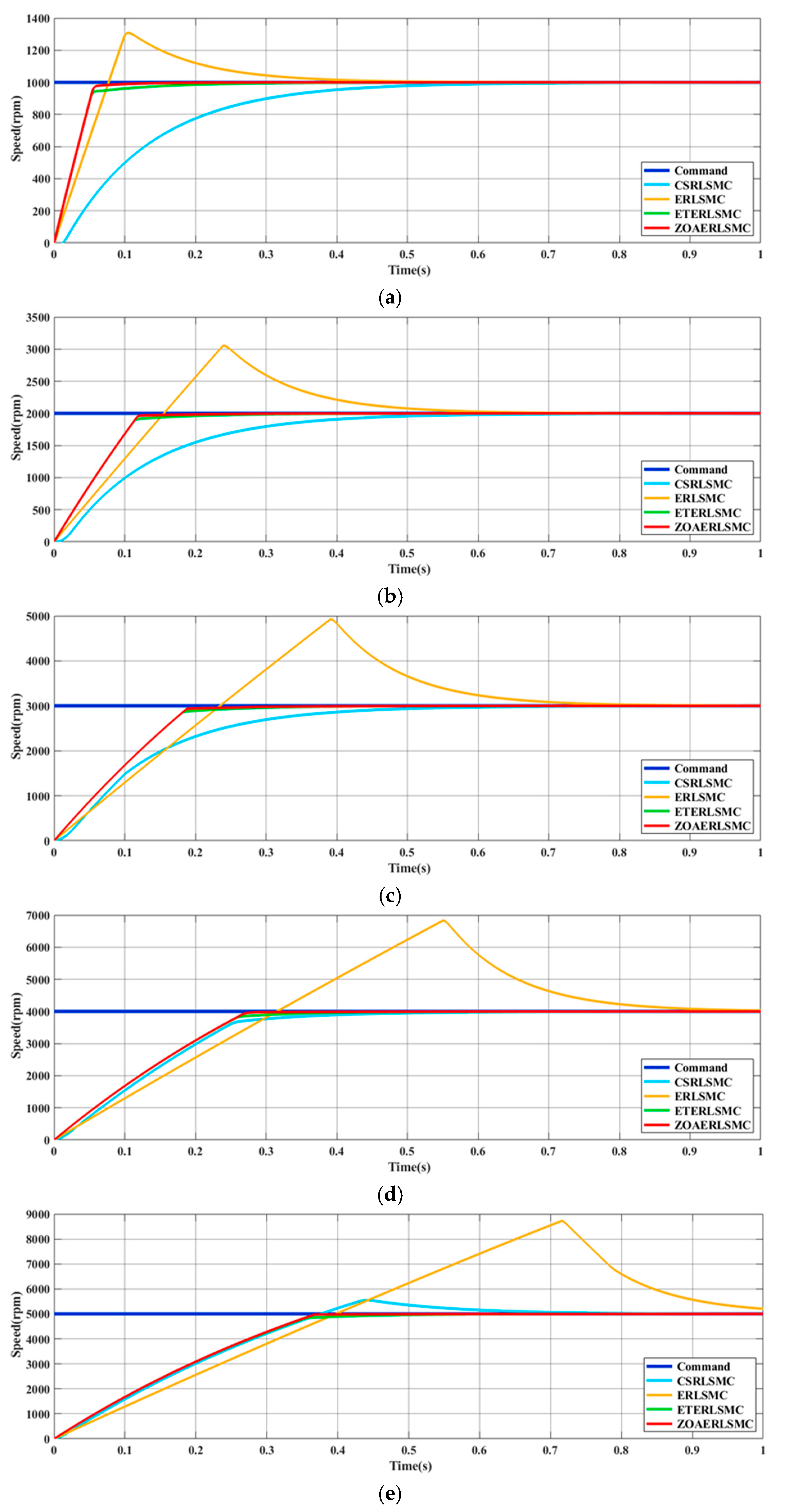
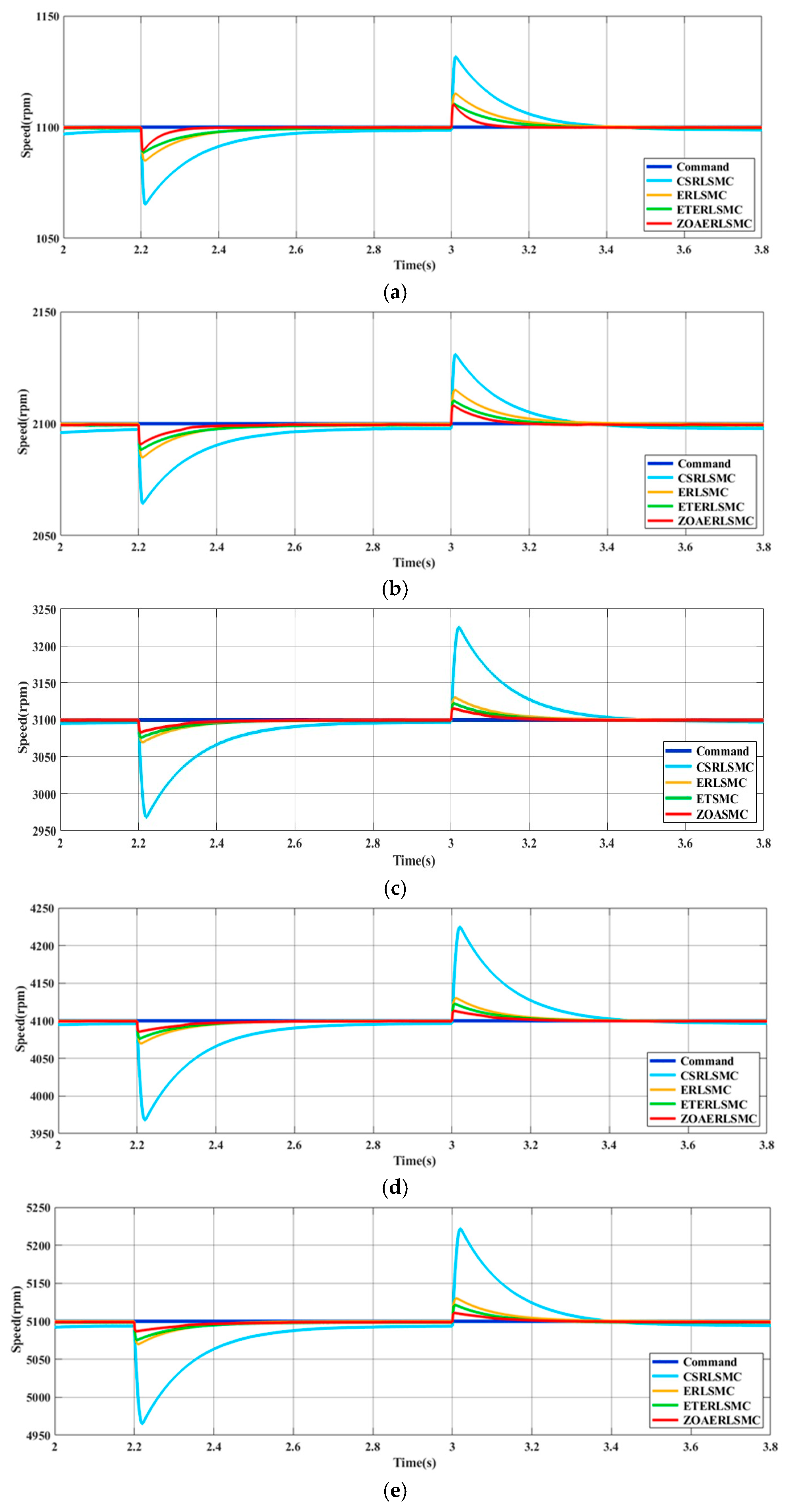
To verify the performance of the proposed robust controller, this study adopted the AM-2200H permanent magnet BLDCM [21] for testing. The motor specifications are listed in Table 2. The speed control performance of the BLDCM drive system is validated through simulations conducted using MATLAB/Simulink (2024b version). This paper compares the speed control performance of the BLDCM under four different control strategies: zebra optimization algorithm combined with exponential reaching law-based sliding mode controller (ZOAERLSMC), constant speed reaching law-based sliding mode controller (CSRLSMC), ERLSMC, and ETERLSMC. Figure 3a–e shows the simulated tracking responses of the BLDCM speed under a constant load of 1 N·m, where the speed command ramps up from 0 rpm to various target speeds (1000 rpm, 2000 rpm, 3000 rpm, 4000 rpm, and 5000 rpm). Figure 4a–e presents the simulated tracking responses under the same 1 N·m load, where each test involves an acceleration of 100 rpm from initial speed commands of (1000 rpm, 2000 rpm, 3000 rpm, 4000 rpm, and 5000 rpm), respectively. Figure 5a–e illustrates the simulated load regulation responses of the motor at speed commands of (1100 rpm, 2100 rpm, 3100 rpm, 4100 rpm, and 5100 rpm). Among these, Figure 5a–c depicts responses under a load variation of 1 N·m, while Figure 5d–e corresponds to cases with a 2 N·m load change. Based on the simulation results, it is observed that the SMC employing only the constant speed reaching law fails to achieve stable tracking of the speed command due to the absence of an integral effect. This results in a longer tracking time and slower load regulation response, accompanied by significant speed drop under load disturbances. Although the SMC using only the exponential reaching law achieves faster tracking compared to the constant speed version, it exhibits noticeable overshoot in its response. As shown in Figure 3 and Figure 4, while the ETERLSMC eliminates the overshoot observed in the ERLSMC, it still fails to simultaneously optimize both the speed tracking performance and the load regulation response. However, by employing the ZOA to dynamically adjust the three gain parameters of the ERLSMC, not only can the overshoot typically associated with standalone ERLSMC be effectively suppressed, but superior control performance can also be achieved in load regulation response compared to the three other types of controllers.

5. Experimental Results

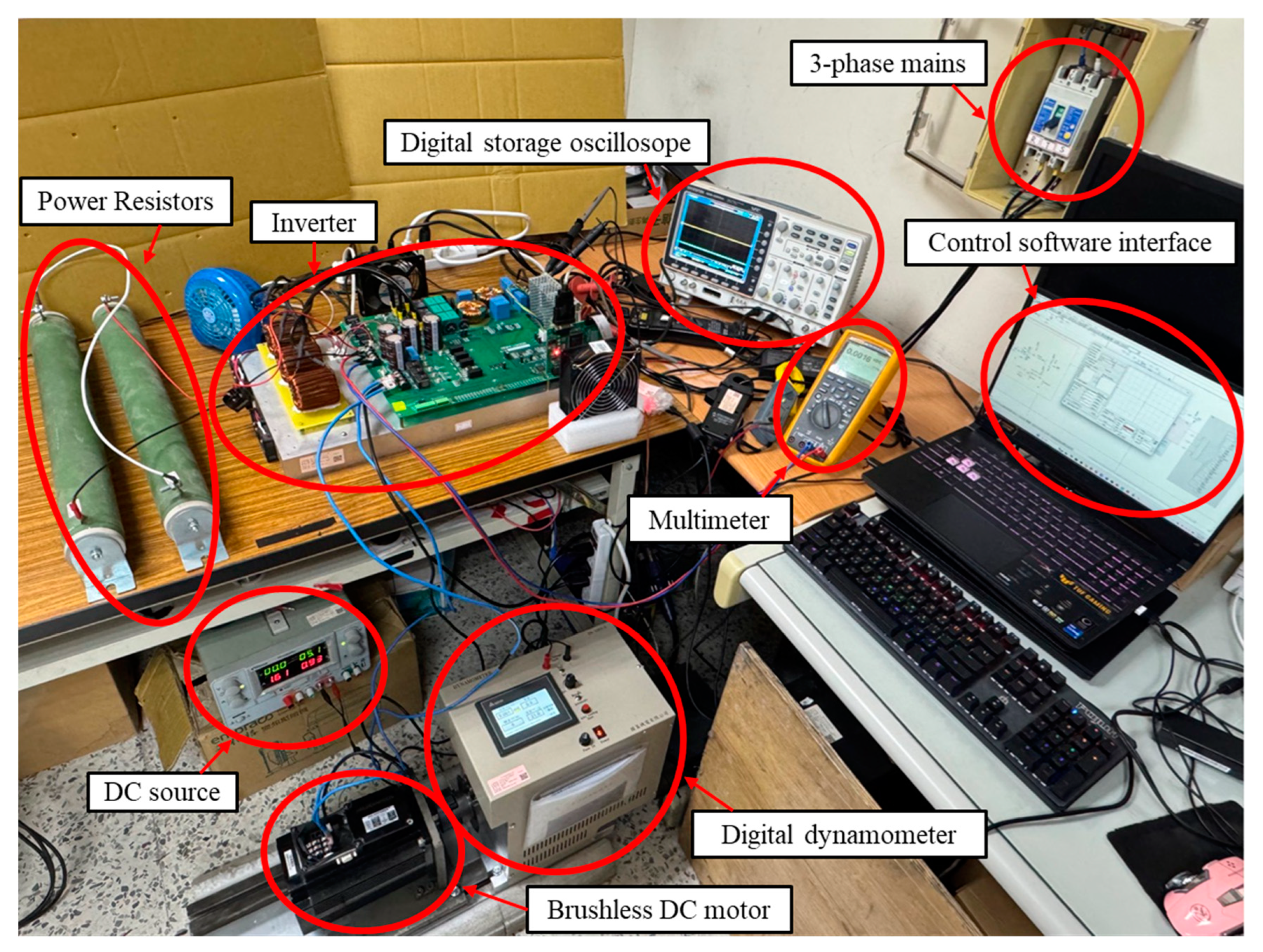
Figure 6 shows the experimental setup of the BLDC motor system used in this study. The inverter is powered by a three-phase AC mains supply and controlled via a control software interface on a laptop, which communicates with a digital signal processor (DSP) based on the TMS320F28335 chip produced by Texas Instruments (TI). This DSP serves as the core control unit for driving the BLDC motor. A digital dynamometer is employed for load regulation tests, while instruments such as multimeter and digital storage oscilloscopes are used to monitor the inverter’s operating status. Additionally, to facilitate repeated experiments, a power resistor connected in parallel with the DC bus voltage and equipped with a switch is used to rapidly discharge the stored energy after each test, thereby reducing the overall experiment duration.
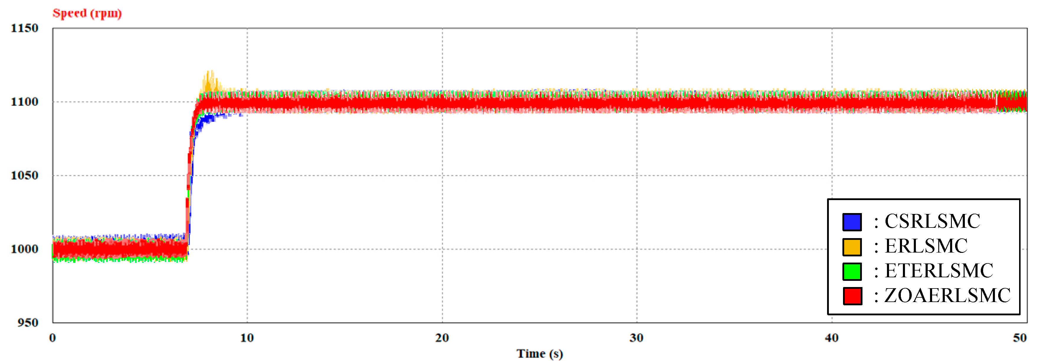
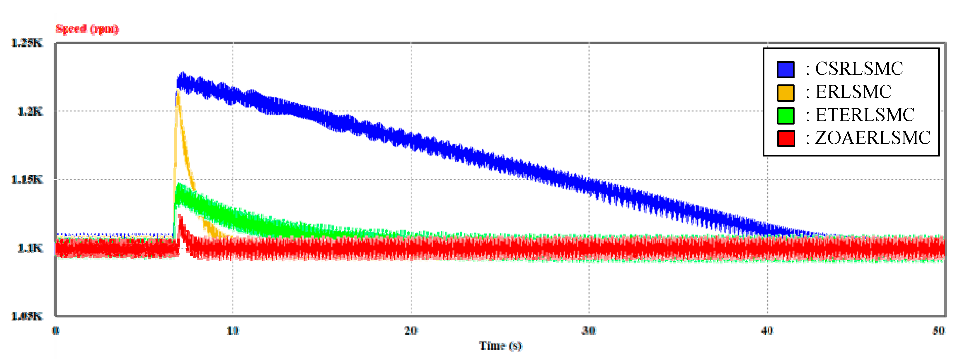
To verify the feasibility of the proposed robust controller, implementation tests were conducted under the same operating conditions as the simulation tests, using four types of SMCs. The performance of the controllers was compared based on speed tracking and load regulation responses, using Case (a) from Figure 3, Figure 4 and Figure 5 as an example. Since a large inrush current may occur during motor startup, which could pose safety concerns during practical implementation, Figure 7 shows the speed tracking response from 0 to 1000 rpm under no-load conditions (0 N·m). Figure 8 presents the response when a 1 N·m load is applied after reaching 1000 rpm, followed by a 100 rpm increase in the speed command after reaching steady state. Figure 9 and Figure 10 illustrate the load regulation responses at 1100 rpm when the load is suddenly increased from 0 N·m to 1 N·m and then suddenly decreased from 1 N·m to 0 N·m, respectively.
The experimental results generally agree with the simulation outcomes. Although the ERLSMC demonstrates favorable performance in load regulation, it exhibits overshoot. The CSRLSMC eliminates overshoot but shows slower responses in both speed tracking and load regulation. The ETERLSMC achieves no overshoot and exhibits smaller speed fluctuations during load changes compared to ERLSMC and CSRLSMC; however, as the control force used to suppress the overshoot of the ERLSMC is too strong, its speed recovery is slower. In contrast, the proposed ZOAERLSMC effectively overcomes these issues and shows superior performance in both speed tracking and load regulation compared to the other three SMCs.

6. Conclusions

In this study, a novel control strategy combining the ZOA with an ERLSMC is proposed to replace the conventional P-I speed controller used in FOC for BLDCM speed regulation. The proposed controller dynamically tunes the three gain parameters of the ERLSMC using the ZOA. This approach enables the real-time adjustment of the gains associated with both the sliding mode dynamic trajectory function and the exponential reaching law, effectively suppressing the overshoot typically observed in conventional ERLSMC designs. At the same time, it overcomes the poor load regulation response exhibited by the CSRLSMC. Moreover, the proposed robust controller demonstrates superior performance in both speed tracking and load regulation when compared to the ETERLSMC. The proposed control strategy not only improves system performance in dynamic speed tracking and disturbance rejection but also features a simple structure that does not require extensive training data, making it easy to implement in practical applications. However, in addition to control performance, electromagnetic interference (EMI) must also be considered in practical applications, as it can significantly impact system stability and electromagnetic compatibility. This is especially critical in motor drive systems with high-frequency switching characteristics, where EMI may cause sensor errors, signal disturbances, or malfunctioning of nearby equipment, ultimately degrading overall control effectiveness. Therefore, the BLDCM drive system employed in this study has been designed and integrated with an EMI suppression circuit to enhance its interference immunity. The controller and drive system have been fully constructed in hardware, with only EMI-related testing and analysis remaining. Future work will focus on evaluating the system’s stability and compatibility under real-world electromagnetic environments.

Author Contributions

K.-H.C. managed the project and completed the formal analysis of the sliding mode controller. K.-H.C. also planned the project and wrote, edited and reviewed the manuscript. K.-H.H. completed the formal analysis of the zebra optimization algorithm. Y.-H.G. is responsible for the software program and simulation results validation. All authors have read and agreed to the published version of the manuscript.

Funding

The authors gratefully acknowledge the support and funding of this project by Industrial Technology Research Institute, Taiwan, under the Grant Number NCUT23TCE09 and NCUT23TCE021.

Institutional Review Board Statement

Not applicable.

Informed Consent Statement

Not applicable.

Data Availability Statement

Data is contained within the article.

Conflicts of Interest

The authors of the manuscript declare no conflicts of interest.

Nomenclature

Acronyms
BLDCMbrushless DC motors
FOCfield-oriented control
ZOAzebra optimization algorithm
SMT sliding mode theory
ERLSMC exponential reaching law-based sliding mode controller
ETextension theory
P-Iproportional-integral
SMCsliding mode controller
2DOFCtwo-degree-of-freedom controller
PSOparticle swarm optimization
EFT2DOFCextendable fuzzy theory with two-degree-of-freedom controller
PSOP-ICparticle swarm optimization algorithm combined with P-I controller
ETERLSMCextension theory combined with exponential reaching law-based sliding mode controller
SVPWMspace vector pulse width modulation
ZOAERLSMCzebra optimization algorithm combined with exponential reaching law-based sliding mode controller
CSRLSMCconstant speed reaching law-based sliding mode controller
Symbols
ϕ d s , ϕ q s stator fluxs of the d-axis and q-axis
ϕ F flux linkage
v d s , v q s stator voltages of the d-axis and q-axis
R s stator resistance
i d s , i q s stator currents of the d-axis and q-axis
ω e electrical angular velocity of the motor
L d , L q stator inductances of the d-axis and q-axis
T e electromagnetic torque
P number of poles
J moment of inertia
ω m mechanical angular velocity
T L load torque
B viscous friction coefficient
K t torque constant
α , β two-phase stationary coordinate
d , q two-phase synchronous rotating coordinate
v α , v β two-phase stationary coordinate voltage
i q s stator reference current of the q-axis
X i , j position of the i-th zebra in the j-th dimension
u b j , l b j lower and upper bounds of the search space in the j-th dimension
r random number uniformly distributed in the range [0, 1]
X i , j n e w , P 1 new position of the i-th zebra in the j-th dimension during the first-stage foraging behavior
P Z j position of the pioneer zebra in the j-th dimension
I randomly selected value from the set {1,2}
X i the current position of the i-th zebra
F i the current fitness value of the i-th zebra
F i n e w , P 1 the fitness value after the first-stage foraging
S 1 , S 2 two defensive strategies
X i , j n e w , P 2 new position of the i-th zebra in the j-th dimension during the second-stage defensive behavior
F i n e w , P 2 the fitness value after the second-stage foraging
R constant set to 0.01
t the current iteration number
T the maximum number of iterations
P s random probability value within [0, 1] that determines the type of predator encountered
A Z j the position of the attacked zebra in the j-th dimension
ω m commanded rotor speed
x 1 speed difference
x 2 rate change of the speed difference
s sliding mode dynamic trajectory function
c sliding mode dynamic trajectory control gain
u control force function
V Lyapunov’s second stability criterion continuous function
s ˙ reaching law functions
e speed difference
e ˙ rate change of the speed difference
W 1 , W 2 weight values

References

  1. Wang, M.; Chen, Z. Research on Permanent Magnet Structure of Permanent Magnet Synchronous Motor for Electric Vehicle. In Proceedings of the 2nd International Conference on Electrical Engineering and Control Science (IC2ECS), Nanjing, China, 16–18 December 2022; pp. 990–993. [Google Scholar]
  2. Lee, C.I.; Jang, G.H. Experimental Measurement and Simulated Verification of the Unbalanced Magnetic Force in Brushless DC Motors. IEEE Trans. Magn. 2008, 44, 4377–4380. [Google Scholar] [CrossRef]
  3. BV, P.; Balamurugan, A.; Selvathai, T.; Reginald, R.; Varadhan, J. Evaluation of Different Vector Control Methds for Electric Vehicle Application. In Proceedings of the 2nd International Conference on Power and Embedded Drive Control (ICPEDC), Chennai, India, 21–23 August 2019; pp. 273–278. [Google Scholar]
  4. Bhatti, S.A.; Malik, S.A.; Daraz, A. Comparison of P-I and I-P Controller by Using Ziegler-Nichols Tuning Method for Speed Control of DC Motor. In Proceedings of the International Conference on Intelligent Systems Engineering (ICISE), Islamabad, Pakistan, 15–17 January 2016; pp. 330–334. [Google Scholar]
  5. Murali, S.B.; Rao, P.M. Adaptive Sliding Mode Control of BLDC Motor Using Cuckoo Search Algorithm. In Proceedings of the 2nd International Conference on Inventive Systems and Control (ICISC), Coimbatore, India, 19–20 January 2018; pp. 989–993. [Google Scholar]
  6. Qi, C.; Xie, J.; Mao, H.; Xie, Q. Condition Assessment of Valve-side Bushing of Converter Transformer Based on Extension Theory. In Proceedings of the IEEE International Conference on High Voltage Engineering and Application (ICHVE), Beijing, China, 6–10 September 2020; pp. 1–4. [Google Scholar]
  7. Trojovská, E.; Dehghani, M.; Trojovský, P. Zebra Optimization Algorithm: A New Bio-inspired Optimization Algorithm for Solving Optimization Algorithm. IEEE Access 2022, 10, 49445–49473. [Google Scholar] [CrossRef]
  8. Chao, K.H.; Hsieh, C.T.; Chen, X.J. A Robust Controller Based on Extension Sliding Mode Theory for Brushless DC Motor Drives. Electronics 2024, 13, 4028. [Google Scholar] [CrossRef]
  9. Chao, K.H.; Chang, C.L. Design of a Robust Controller for Induction Motor Drive Systems Based on Extendable Fuzzy Theory. Mathematics 2024, 12, 3235. [Google Scholar] [CrossRef]
  10. Chen, G.Y.; Perng, J.W.; Ma, L.S. DSP Based BLDC Motor Controller Design with Auto Tuning PSO-PID Algorithm. In Proceedings of the IEEE/SICE International Symposium on System Integration (SII), Nagoya, Japan, 11–13 December 2015; pp. 766–770. [Google Scholar]
  11. Wang, J.; Ye, J.; Yan, R. The Magnetostatic Simulation and Determination of Magnetic Components for an External Ventricular Drainage Device. In Proceedings of the 40th Chinese Control Conference (CCC), Shanghai, China, 26–28 July 2021; pp. 6386–6391. [Google Scholar]
  12. Liu, C.H. AC Motor Control: Principles of Vector Control and Direct Torque Control, 4th ed.; Donghua Book Company: Taipei, Taiwan, 2007. [Google Scholar]
  13. Xie, T.; Kuai, Z.; Ye, X.; Zhu, L.; Guo, K.; Shi, S. Coordinate Conversions and Deviation Analysis in Multi-source Data Fusion. In Proceedings of the 2nd China International SAR Symposium (CISS), Shanghai, China, 3–5 November 2021; pp. 1–3. [Google Scholar]
  14. Kishore, N.; Shukla, K.; Gupta, N. A Novel Three-Phase Multilevel Inverter Cascaded by Three-Phase Two-Level Inverter and Two Single-Phase Boosted H-Bridge Inverters. In Proceedings of the IEEE PES Innovative Smart Grid Technologies-Asia (ISGT Asia), Singapore, 1–5 November 2022; pp. 330–334. [Google Scholar]
  15. Butt, C.; Hoque, M.A.; Rahman, M.A. Simplified Fuzzy Logic Based MTPA Speed Control of IPMSM Drive. IEEE Trans. Ind. Appl. 2004, 40, 1529–1535. [Google Scholar] [CrossRef]
  16. Luo, N.; Zhang, L. Chaos Driven Development for Software Robustness Enhancement. In Proceedings of the 9th International Conference on Dependable Systems and Their Applications (DSA), Wulumuqi, China, 4–5 August 2022; pp. 1029–1034. [Google Scholar]
  17. Song, H.; Zhang, M.; Shi, Q. Capacity Optimization of Hybrid Energy Storage System Based on Improved Zebra Optimization Algorithm. In Proceedings of the 2024 IEEE 7th Information Technology, Networking, Electronic and Automation Control Conference (ITNEC), Chongqing, China, 20–22 September 2024; pp. 1390–1394. [Google Scholar]
  18. Lebedev, A.; Filaretov, V. Adaptive Variable Structure System with the Sliding Surfaces Adjustment for the Control of Nonstationary Linear Object. In Proceedings of the 2008 IEEE International Conference on Mechatronics and Automation, Takamatsu, Japan, 5–8 August 2008; pp. 684–689. [Google Scholar]
  19. Zhang, J.; Liu, B.; Jiang, Z.; Hu, H. The Application of Sliding Mode Control with Improved Approaching Law in Manipulator Control. In Proceedings of the 13th IEEE Conference on Industrial Electronics and Applications (ICIEA), Wuhan, China, 31 May–2 June 2018; pp. 807–812. [Google Scholar]
  20. Bodur, F.; Kaplan, O. A Novel Sliding Mode Control Based on Super Twisting Reaching Law for PMSM Speed Controller with Fixed-Time Disturbance Observer. In Proceedings of the 12th International Conference on Renewable Energy Research and Applications (ICRERA), Oshawa, ON, Canada, 29 August–1 September 2023; pp. 1–6. [Google Scholar]
  21. AM2200H BLDC Motor. Available online: https://www.adlee.com/zh-tw/product-552515/%E5%B7%A5%E6%A5%AD%E7%94%A8%E7%9B%B4%E6%B5%81%E7%84%A1%E5%88%B7%E9%A6%AC%E9%81%94.html (accessed on 8 May 2024).
Figure 1. Block diagram of the FOC architecture for the BLDCM drive system used in this study.
Electronics 14 03353 g001
Figure 2. Proposed control flowchart of the ZOA.
Electronics 14 03353 g002
Figure 3. Comparison of tracking responses under a 1 N·m load between the proposed robust controller and the following three controllers: (i) CSRLSMC, (ii) ERLSMC, and (iii) ETERLSMC. In this scenario, the speed command increases from 0 rpm to various target values: (a) ω r : 0 1000 rpm; (b) ω r : 0 2000 rpm; (c) ω r : 0 3000 rpm; (d) ω r : 0 4000 rpm; (e) ω r : 0 5000 rpm.
Electronics 14 03353 g003
Figure 4. Comparison of tracking responses under a 1 N·m load between the proposed robust controller and the following three controllers: (i) CSRLSMC, (ii) ERLSMC, and (iii) ETERLSMC. In this scenario, each speed command increases by 100 rpm at 1.5 s from the following initial values: (a) ω r : 1000 1100 rpm; (b) ω r : 2000 2100 rpm; (c) ω r : 3000 3100 rpm; (d) ω r : 4000 4100 rpm; (e) ω r : 5000 5100 rpm.
Electronics 14 03353 g004
Figure 5. Comparison of load regulation responses between the proposed robust controller and the following three controllers: (i) CSRLSMC, (ii) ERLSMC, and (iii) ETERLSMC. In this scenario, a load is applied at 2.2 s and removed at 3.0 s under different speed command conditions: (a) ω r : 1100 rpm, T L : 0 1 0 N·m; (b) ω r : 2100 rpm, T L : 0 1 0 N·m; (c) ω r : 3100 rpm, T L : 0 1 0 N·m; (d) ω r : 4100 rpm, T L : 0 2 0 N·m; (e) ω r : 5100 rpm, T L : 0 2 0 N·m.
Electronics 14 03353 g005
Figure 6. Experimental setup of brushless DC motor drive control.
Electronics 14 03353 g006
Figure 7. Comparison of the measured speed command tracking response waveforms of the proposed ZOAERLSMC, the ETERLSMC, the ERLSMC, and the CSRLSMC ( T L : 0 N·m, ω r : 0 1000 rpm).
Electronics 14 03353 g007
Figure 8. Comparison of the measured speed command tracking response waveforms of the proposed ZOAERLSMC, the ETERLSMC, the ERLSMC, and the CSRLSMC ( T L : 1 N·m, ω r : 1000 1100 rpm).
Electronics 14 03353 g008
Figure 9. Comparison of the measured load speed recovery responses between the proposed ZOAERLSMC, the ETERLSMC, the ERLSMC, and the CSRLSMC ( T L : 0 1 N·m, ω r : 1100 rpm).
Electronics 14 03353 g009
Figure 10. Comparison of the measured load speed recovery responses between the proposed ZOAERLSMC, the ETERLSMC, the ERLSMC, and the CSRLSMC ( T L : 1 0 N·m, ω r : 1100 rpm).
Electronics 14 03353 g010
Table 1. The parameter values used by the ZOA of the proposed controller.
ParametersValue
The number of zebras (N)5
Maximum number of iterations (T)30
The   range   of   sliding   mode   dynamic   trajectory   control   gain   [ c m i n , c max ][350, 7000]
The   range   of   exponential   reaching   gain   [ q m i n , q m a x ][0.1, 3.5]
The   range   of   constant   speed   reaching   gain   [ ε m i n , ε m a x ][0.1, 1]
The range of random number (r)[0, 1]
Population variation index (I){1, 2}
The range of random number of strategy switching probability (Ps)[0, 1]
Constant (R)0.01
Weight   coefficient   of   speed   error   ( W 1 )0.7
Weight   coefficient   of   the   rate   of   change   in   speed   error   ( W 2 )0.3
Table 2. Specifications of the adopted BLDCM.
Electrical SpecificationsValue
Three-phase rated voltageAC 220 V
Three-phase rated currentAC 9.8 A
Rated apparent power2156 VA
Rated speed6000 rpm
Operating frequency range0 ~ 200 Hz
Number of poles4
Stator resistance1.5 × 10−1 Ω
Stator inductance1.235 × 10−3 H
Flux linkage1.26 × 10−1 Wb
Moment of inertia1.45 × 10−3 ( Kg · m 2 )
Viscous friction coefficient2.38 × 10−3 ( N · m · s )
Disclaimer/Publisher’s Note: The statements, opinions and data contained in all publications are solely those of the individual author(s) and contributor(s) and not of MDPI and/or the editor(s). MDPI and/or the editor(s) disclaim responsibility for any injury to people or property resulting from any ideas, methods, instructions or products referred to in the content.