Article

A New Dimensional Target Scattering Characteristic Characterization Method Based on the Electromagnetic Vortex-Polarization Joint Scattering Matrix

1
National Key Laboratory of Microwave Imaging, Aerospace Information Research Institute, Chinese Academy of Sciences, Beijing 100094, China
2
School of Electronic, Electrical and Communication Engineering, University of Chinese Academy of Sciences, Beijing 100049, China
3
National Key Laboratory of Science and Technology on Space Microwave, Xi’an Institute of Space Radio Technology, Xi’an 710100, China
*
Author to whom correspondence should be addressed.
Electronics 2025, 14(17), 3346; https://doi.org/10.3390/electronics14173346
Submission received: 14 July 2025 / Revised: 8 August 2025 / Accepted: 20 August 2025 / Published: 22 August 2025

Abstract

Vortex electromagnetic (EM) waves exhibit spiral wavefront phase distributions, owing to their orbital angular momentum (OAM). Thus, the scattered waves from targets contain OAM characteristics, demonstrating novel scattering properties. Although researchers have carried out both theoretical and experimental studies on the target scattering characteristics of vortex EM waves, a comprehensive and standardized characterization framework is still lacking. This paper proposes and defines an EM vortex scattering matrix (EVSM), which can be used as a characterization method for the target scattering characteristics in the OAM dimension of vortex EM waves. Since vortex EM waves carry both OAM and spin angular momentum (SAM), the EM vortex-polarization joint scattering matrix (EVPJSM) is defined by extending EVSM. This joint matrix simultaneously describes the target scattering characteristics in both OAM and SAM dimensions of vortex EM waves. And it can offer a thorough framework of target scattering characteristics for arbitrary OAM–SAM combinations in new-dimensional EM waves. Numerical simulations are performed to compute each element in EVPJSM for two typical targets under twelve different pairs of OAM modes and two SAM polarization combinations. The numerical results can be used as an example of the characterization method in new dimensions for the targets’ scattering characteristics.

1. Introduction

A vortex electromagnetic (EM) wave is a brand new form of EM wave, which has unique advantages and potential applications in multiple fields such as target detection, super-resolution imaging, three-dimensional target reconstruction, and communication multiplexing and capacity expansion. It has attracted much attention from researchers in recent years. Compared with traditional plane EM waves, vortex EM waves carry orbital angular momentum (OAM) information and have a new dimension of information modulation degrees of freedom, demonstrating new target scattering characteristics.
Research on OAM originated in the field of optics [1]. Allen et al. discovered that the wavefront of the Laguerre–Gaussian beam was helical, confirming that the beam carried OAM [2]. This led to a breakthrough in the research on OAM. The Garces-Chavez team observed that the high-order Bessel beam carried OAM and analyzed its OAM mode [3]. Thide et al. generated OAM beams with four modes using a circular array [4]. This research introduced OAM and vortex EM waves to radar detection applications, making target scattering characteristics based on vortex EM waves a significant research focus in recent years. Bu et al. studied the backscattering characteristics of vortex EM waves for typical targets, i.e., corner reflectors, flat plates [5], and ideal conductive spikes with different interior angles. They found that the radar cross section (RCS) of vortex EM waves was different from plane waves and varied with the OAM mode, which was more conducive to detecting low RCS targets in certain directions [6]. Guo et al. conducted research on the scattering characteristics of vortex EM waves of different OAM modes on coated spheres [7]. Liu et al. first proposed the concept of the OAM radar cross section (ORCS), derived the analytical expression of ORCS for typical targets, and systematically discussed the target scattering characteristics of vortex EM waves [8]. Liu et al. further studied the backscattering characteristics of vortex EM waves in typical large-sized spheres and cones, which proved that OAM beams can provide more information for target detection and recognition compared with plane waves [9]. Fang et al. used the electrically large sea surface surveillance ship as the target to analyze the scattering characteristics of vortex EM waves [10]. Arfan et al. compared scattering characteristic differences between plane EM waves and vortex EM waves for a PEC sphere [11]. Bu et al. proposed an inverse synthetic aperture radar (ISAR) imaging method for high-speed maneuvering targets using vortex EM waves, experimentally verifying their phase sensitivity and anti-jamming capability in complex target scattering [12]. Chen et al. obtained analytical formulas for scattered near-fields from arbitrary metallic targets illuminated by Bessel vortex beams using angular spectrum expansion and then computed OAM distributions and target RCS for both simple and composite structures [13]. Wang et al. analyzed the backscattering characteristics of vortex EM waves on symmetric targets and observed that the backscattering characteristics of the symmetric targets are asymmetric [14]. Sun et al. studied the impact of target materials on scattered field intensity and OAM spectrum distributions under vortex electromagnetic wave illumination. Their findings showed that coated targets better preserve incident wave OAM modes, whereas metallic targets are the most sensitive to beam parameter alterations [15]. In brief, the present research confirms that OAM provides a new dimension for describing target scattering characteristics, leading to unique advantages in target detection. To date, the vast majority of research focuses on theoretical and practical studies of the target scattering characteristics of vortex EM waves, while a unified and thorough characterization methodology is still lacking. The matrices constructed in this paper can address this gap.
The scattering characteristics of radar targets are not only related to the target material, structure, attitude angle, etc., but also to the polarization state of EM waves. The polarization scattering matrix (PSM) is an important tool for describing the target scattering characteristics. The concept of polarization scattering was first proposed in the 1940s. George first put forward the second-order PSM to describe the target scattering characteristics of polarized EM waves [16], laying the theoretical foundation for characterizing the target scattering characteristics. Huynen et al. proposed the phenomenological theory of radar targets and the basic theory of Huynen target decomposition, establishing the connection between target echo data and target physical characteristics [17]. His theory promoted further research on the physical interpretability of polarization information. Based on PSM, Cloude et al. and Freeman et al., respectively, presented Cloude–Pottier entropy/ α decomposition [18] and Freeman–Durden tricomponent decomposition [19]. At present, PSM still holds a core position in the characterization of target scattering characteristics and is applied in fields such as target polarization information acquisition [20], target scattering characteristic analysis [21], and the decomposition and identification of complex targets [22,23].
However, with the in-depth study of OAM, researchers have realized that targets show new scattering characteristics in this new dimension. Relying only on PSM to describe the target scattering characteristics is inherently limiting, especially for stealth targets and specially engineered structures with distinct scattering characteristics. Therefore, combining PSM and the OAM dimension can offer comprehensive target characterization. It is expected to improve the capacity to identify targets. By adding OAM as a new dimension, this paper develops a characterization framework for target scattering characteristics of vortex EM waves based on the theory and mathematical formalism of PSM. According to the orthogonal characteristics of the vortex EM wave modes, an EM vortex scattering matrix (EVSM) and an EM vortex-polarization joint scattering matrix (EVPJSM) were constructed progressively. The proposed matrices fully characterized target scattering characteristics of vortex EM waves simultaneously in both OAM and SAM dimensions. Moreover, they address challenges, such as difficult scattering feature extraction and low target recognition probability, to some extent, while extending OAM’s applicability in scattering characterization domains.

2. Fundamental Properties of Vortex EM Waves

According to classical EM theory, the momentum carried by an EM wave when it propagates can be divided into linear momentum (LM) and angular momentum (AM). Furthermore, AM consists of SAM and OAM. SAM is related to the polarization state of the EM wave. OAM is related to the phase space distribution in the wavefront of the EM wave [24]. The expression of the AM carried by EM waves is:
J = L + S ,
where J , L and S represent AM, SAM and OAM respectively.
Plane EM waves only carry SAM information, while vortex EM waves carry information in both SAM and OAM dimensions simultaneously.

2.1. OAM Characterizes of EM Waves

OAM characterizes the fundamental properties of vortex EM waves and is one of its important physical characteristics.
OAM is related to the phase space distribution in the wavefront of the EM wave. Compared with plane EM waves, the wave function of vortex EM waves contains a phase term U r , φ that is related to the spatial azimuth angle:
U r , φ = A r e j l φ ,
where r is the position vector from a certain point to the beam axis in the EM field space, A r is the amplitude of the traditional EM wave, l is the topological charge of OAM beams, and φ is the azimuth angle around the beam axis. From Equation (2), it can be seen that the phase distribution of the vortex EM wave is related to the topological charge. The equiphase surfaces spirally propagate, which leads to a phase singularity forming on the beam axis, resulting in a special wavefront phase distribution that differs from the plane EM waves (Figure 1).

2.2. SAM Characterization of EM Waves and Polarization Scattering Matrix

Different modes of vortex EM waves have different phase distributions. When vortex EM waves with different modes are irradiated onto the same target, their target scattering characteristics will be different. Each mode of vortex EM waves is mutually orthogonal. Thus, any two orthogonal modes can form a modal orthogonal base. Compared with polarized waves, vortex EM waves theoretically have infinite modes in the OAM dimension. Therefore, an OAM beam contains infinite pairs of orthogonal bases. This feature can serve as a new dimension and method for quantitatively characterizing the target scattering characteristics in the OAM dimension of vortex EM waves.
SAM is related to the polarization state of EM waves. The scattered wave formed after the incident wave irradiates the target contains various polarization components of SAM. Generally, an arbitrarily polarized electric field can be decomposed into a pair of orthogonal polarization bases. It is the polarization base that can describe the target scattering characteristics. The horizontal–vertical base E H E V T , rotating linear polarization matrix E A E B T , and left-hand–right-hand circularly polarized base E R E L T are three widely used polarization bases [26]. They can represent each other through coordinate transformation. When an arbitrarily polarized wave is incident on the target, the expressions of the polarization scattering field under different polarization bases [27] are as follows:
E s = E 1 s E 2 s = s 11 s 12 s 21 s 22 E 1 i E 2 i = S E i ,
where S is PSM; the superscript i represents the incident field, and s represents the scattering field, i.e., E i represents the incident electric field, and E s represents the scattering electric field. The subscripts 1 and 2 represent any combination of orthogonal polarization; thus, s 11 , s 12 , s 21 and s 22 represent the SAM polarization scattering coefficients of any combination of orthogonal polarization, respectively. When the subscript combinations are H and V , it represents the linear polarization bases; when they are A and B , it represents the rotational linear polarization bases; when they are R and L , it represents the circular polarization bases. Each element in the matrix is complex.
Equation (3) shows that PSM is composed of a two-dimensional matrix of size 2 × 2 , which fully reflects the relationship between the incident electric field and the scattering electric field. PSM contains rich information such as the shape, size, structure, and attitude of the target. It can be seen that PSM can effectively represent the target scattering characteristics.
For complex targets, the decomposition of PSM is usually utilized to break them down into combinations of several typical goals, allowing each component of the targets to be described in detail.
In the field of radar detection, the target scattering characteristics presented by vortex EM waves include two dimensions: OAM and SAM. PSM is used to describe the target scattering characteristics in the SAM dimension. As a new dimension, the orthogonal characteristics of OAM provide new ideas and methods for research on the characterization methods of target scattering characteristics in the OAM dimension, as well as the joint target scattering characterization methods of OAM and SAM.

3. The EM Vortex Scattering Matrix

3.1. Definition of the EM Vortex Scattering Matrix

Based on the orthogonal characteristic between different modes of vortex EM waves, this paper defines a new target scattering matrix, called the EM vortex scattering matrix (EVSM), to describe the target scattering characteristics based on the new dimension of OAM for vortex EM waves. Based on orthogonal modes, the phase term e j l φ of the vortex EM wave function is decomposed and expanded.
Analogous to PSM, a vortex EM wave containing mode ± l is incident on the target, forming a scattered wave with mode ± l . The backscattering field is expressed as:
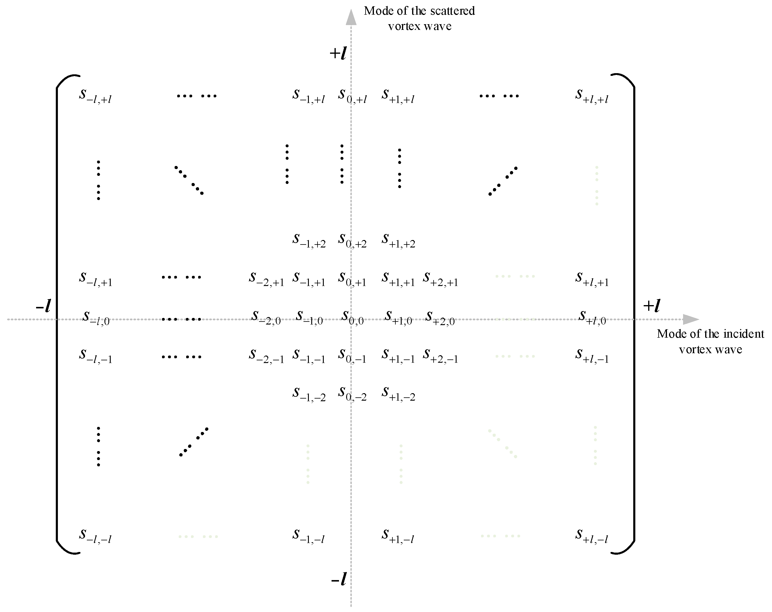
E O A M s = E + l s E + 1 s E 0 s E 1 s E l s = s l , + l s 1 , + l s 0 , + l s + 1 , + l s + l , + l s l , + 1 s 1 , + 1 s 0 , + 1 s + 1 , + 1 s + l , + 1 s l , 0 s 1 , 0 s 0 , 0 s + 1 , 0 s + l , 0 s l , 1 s 1 , 1 s 0 , 1 s + 1 , 1 s + l , 1 s l , l s 1 , l s 0 , l s + 1 , l s + l , l E l i E 1 i E 0 i E + 1 i E + l i = S v E O A M i ,
where the superscript i , s represent the incident field and the scattering field respectively, i.e., E O A M i , E O A M s represents the incident vortex electric field and the scattering vortex electric field. S v is EVSM, where each element in the matrix is represented by s m , n . The subscript m , n represent the mode of incident and scattered wave, respectively, m , n = 0 , ± 1 , ± 2 , ± l . s m , n are the scattering coefficients corresponding to any modal orthogonal bases of incident and scattered vortex EM waves. All elements are complex numbers.
Based on the definition of s m , n , the expression for calculating s m , n is given by:
s m , n = E O A M , n s E O A M , m i = E n m e j k r e j n φ E m m e j k r e j m φ ,
where E O A M , m i represents the incident vortex electric field of mode m , and E O A M , n s represents the scattered vortex electric field of mode n . E m m and E n m represent the amplitudes of the incident and scattered fields, respectively. E m m = E 0 J m ( k ρ ρ ) and E n m depends on target properties such as type, size, and material.
In order to be convenient for subsequent analysis, a plane rectangular coordinate system is established with the incident wave mode value as the horizontal axis and the scattered wave mode value as the vertical axis. Point O is the origin of the coordinate system. The matrix form of S v is shown in Figure 2.

3.2. Implication of the Elements in EVSM

The OAM mode for incident and scattered vortex EM waves includes positive and negative values. Therefore, EVSM contains four combinations of incident-scattered modes (Table 1). These four combinations respectively correspond to the physical meanings represented by the four quadrants of the coordinate system (Figure 2). Thus, the elements in EVSM are divided into four groups, denoted as the submatrices S v k of EVSM, where k = 1 , 2 , 3 , 4 . The meanings of the elements in the four submatrices are the scattering coefficients corresponding to any combination of the incident wave and the scattered wave of the multimodal vortex EM wave. The specific corresponding relationships are shown in Table 1.
The elements in EVSM located on the horizontal axis represent plane EM wave reception, while those on the vertical axis represent plane EM wave incidence.
The size of each submatrix of EVSM is l × l , in total containing l 2 elements. Thus, all quadrants contain a total of 4 l 2 elements. The scattering coefficient distributed on the coordinate axis contains 4 l + 1 elements. Therefore, EVSM contains a total of ( 2 l + 1 ) 2 elements.
The scattering scenario of an incident wave with mode p and a scattered wave with mode q corresponds to the element s p , q in EVSM, while the scenario of incident and scattered modes is q and p , respectively, and corresponds to the element s q , p . The two scenarios represent two distinct scattering processes. However, both of these scattering scenarios involve the same pair of modal orthogonal bases, E p E q T . Therefore, the orthogonal base pairs of vortex EM waves with mode ± l under all possible incident-scattered mode combinations sum to ( l + 1 ) ( 2 l + 1 ) , which can match the number of the corresponding upper triangular matrix elements of EVSM.
It is worth noting that the OAM mode of the plane EM wave is 0. When the mode of the vortex EM wave degenerates to 0, its morphology of an EM wave will degenerate into a plane wave, so that the EVSM will degenerate into an element of the traditional PSM. In other words, s 0 , 0 represents the scattering coefficient of the incident and scattered traditional plane wave.

4. The EM Vortex-Polarization Joint Scattering Matrix

4.1. Definition of the EM Vortex-Polarization Joint Scattering Matrix

Since vortex EM waves can carry AM information in both OAM and SAM dimensions, this section further expands the dimensionality of the target scattering matrix based on the EVSM. Fusing the EVSM and PSM, we construct a three-dimensional matrix to completely describe the target scattering characteristics of vortex EM waves in both OAM and SAM dimensions.
Firstly, we make assumptions for the OAM and SAM of the vortex EM wave. The OAM of vortex EM waves still takes the incident and scattered vortex EM waves with mode ± l as an example. The SAM of vortex EM waves is illustrated by taking the horizontal–vertical (HV) polarization bases as an example. Without loss of generality, the polarization bases can also be other polarization couples, such as left-hand–right-hand circular polarization or other mutually orthogonal oblique polarizations and elliptical polarizations. The polarization combinations formed by the horizontal–vertical polarization bases are HH, HV, VH, and VV, which respectively represent both incident and scattered waves as horizontal polarization waves; the incident wave is a horizontal polarization wave, and the scattered wave is a vertical polarization wave; the incident wave is a vertical polarization wave, and the scattered wave is a horizontal polarization wave; and both incident and scattered waves are vertical polarization waves.
When the polarization combination of SAM is X Y , a vortex EM wave containing mode ± l is incident on the target, forming a scattered wave with mode ± l . The backscattering field is expressed as:
E O A M s , X Y = E + l s , X Y E + 1 s , X Y E 0 s , X Y E 1 s , X Y E l s , X Y = s l , + l X Y s 1 , + l X Y s 0 , + l X Y s + 1 , + l X Y s + l , + l X Y s l , + 1 X Y s 1 , + 1 X Y s 0 , + 1 X Y s + 1 , + 1 X Y s + l , + 1 X Y s l , 0 X Y s 1 , 0 X Y s 0 , 0 X Y s + 1 , 0 X Y s + l , 0 X Y s l , 1 X Y s 1 , 1 X Y s 0 , 1 X Y s + 1 , 1 X Y s + l , 1 X Y s l , l X Y s 1 , l X Y s 0 , l X Y s + 1 , l X Y s + l , l X Y E l i , X Y E 1 i , X Y E 0 i , X Y E + 1 i , X Y E + l i , X Y = S a m X Y E O A M i , X Y ,
where the superscript includes two parts: firstly, i , s represents the incident field and the scattered field, respectively; secondly, X , Y represents the polarization direction of the incident wave and the scattered wave, respectively, where both X and Y can be H or V. Thus, the superscript XY represents the SAM polarization combination of the current element, i.e., E O A M i , X Y and E O A M s , X Y is the incident and scattered vortex electric field under the SAM polarization combination X Y , s m , n X Y represents the elements in the matrix. The subscript m , n respectively represents the mode of the incident wave and the scattered wave, where m , n = 0 , ± 1 , ± 2 , , ± l . Each element is a complex number. s m , n X Y are the scattering coefficients corresponding to any modal orthogonal bases in OAM mode of incident and scattered vortex EM waves under a certain SAM polarization combination.
Based on the definition of s m , n X Y , it can be calculated as follows:
s m , n X Y = E O A M , n s , X Y E O A M , m i , X Y = E n m Y e j ( ω t k z ) e j n φ E m m X e j ( ω t k z ) e j m φ ,
where E O A M , m i represents the incident vortex electric field of mode m in OAM and H-polarized in SAM, and E O A M , n s represents the scattered vortex electric field of mode n in OAM and V-polarized in SAM. E m m X and E n m Y represent the amplitudes of the incident and scattered field respectively. The amplitude of the incident field is expressed as E m m X = E 0 J m ( k ρ ρ ) ( α 1 x ± α 2 y ) , where α 1 and α 2 are real coefficients. When α 1 0 and α 2 = 0 , it is H-polarized EM wave, while when α 2 0 and α 1 = 0 , it is V-polarized. E n m Y depends on target properties such as type, size and material.
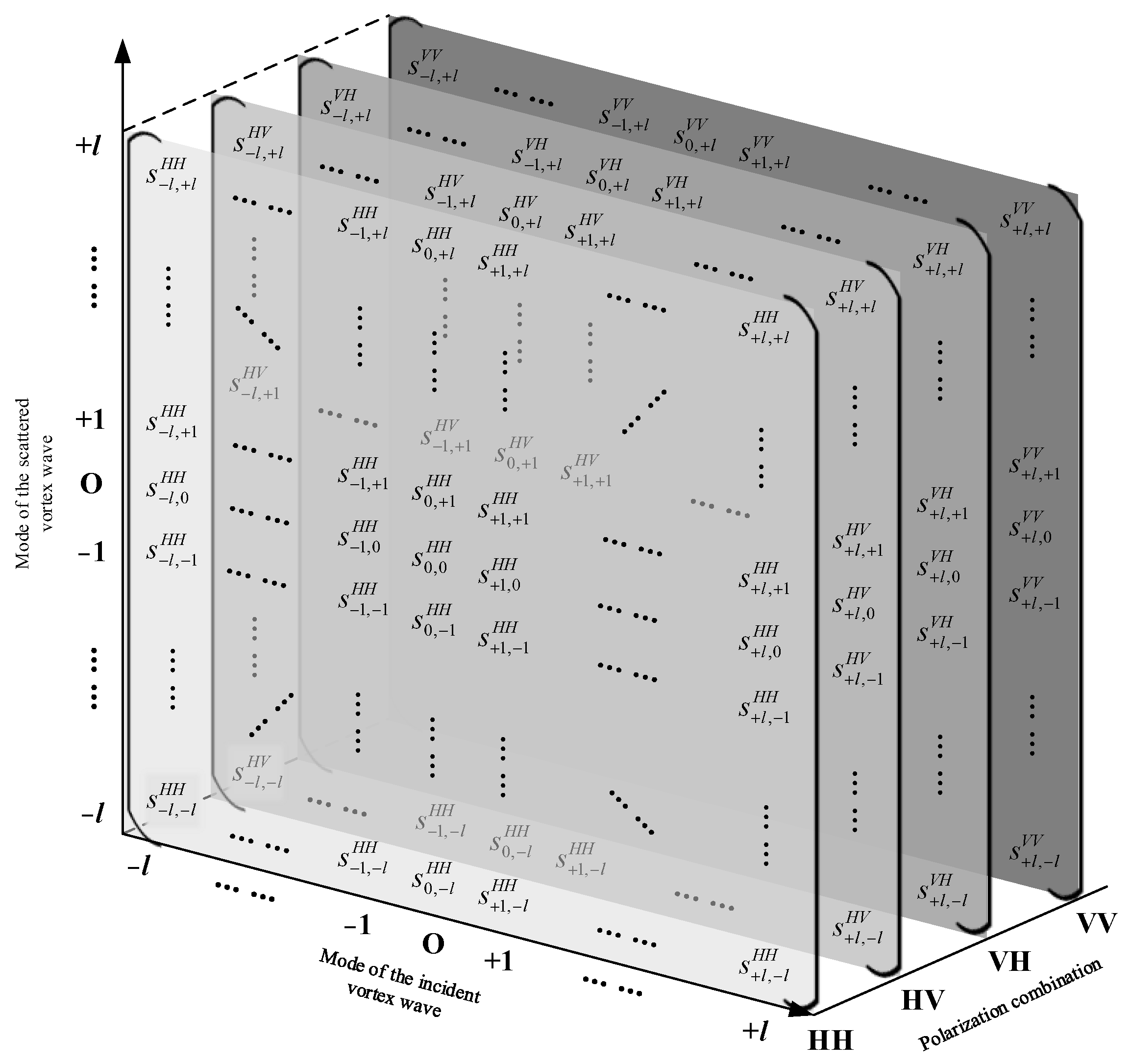
A three-dimensional Cartesian coordinate system is established, with its three coordinate axes respectively representing the incident wave OAM mode, the scattered wave OAM mode, and the SAM polarization combination (Figure 3). Equation (6) is stacked in the order of the SAM polarization combination axes to obtain a three-dimensional matrix, which is named the EM vortex-polarization joint scattering matrix (EVPJSM) and represented by the symbol S a m .
As shown in Figure 3, the target scattering coefficient of an SAM polarization combination is located in a planar matrix. The four polarization combinations of SAM correspond to four planar matrices, respectively denoted as S a m H H , S a m H V , S a m V H , and S a m V V , which are the EVSM constructed in Section 3.
Compared with EVSM, EVPJSM introduces the SAM dimension to the matrix. The morphology of the matrix expands from a planar matrix to a three-dimensional matrix, and the size of the matrix expands from ( 2 l + 1 ) × ( 2 l + 1 ) to ( 2 l + 1 ) × ( 2 l + 1 ) × 4 .
In conclusion, EVPJSM describes the target characteristics simultaneously from the two dimensions of OAM and SAM of the vortex EM wave, containing more comprehensive information on the target scattering characteristics. EVPJSM makes the analysis of the target scattering characteristics very convenient from either the perspective of “the same SAM combination” or “the same OAM transmitting–receiving mode combination.” The scattering coefficients can be readily extracted from EVPJSM under the conditions required for analysis. The scattering coefficients in Equation (6) or (8) can be easily obtained, according to the specific requirements of different tasks. This can further enhance the radar system’s ability to extract the target characteristics and classify the target.

4.2. The Degradation Problem of the EVPJSM

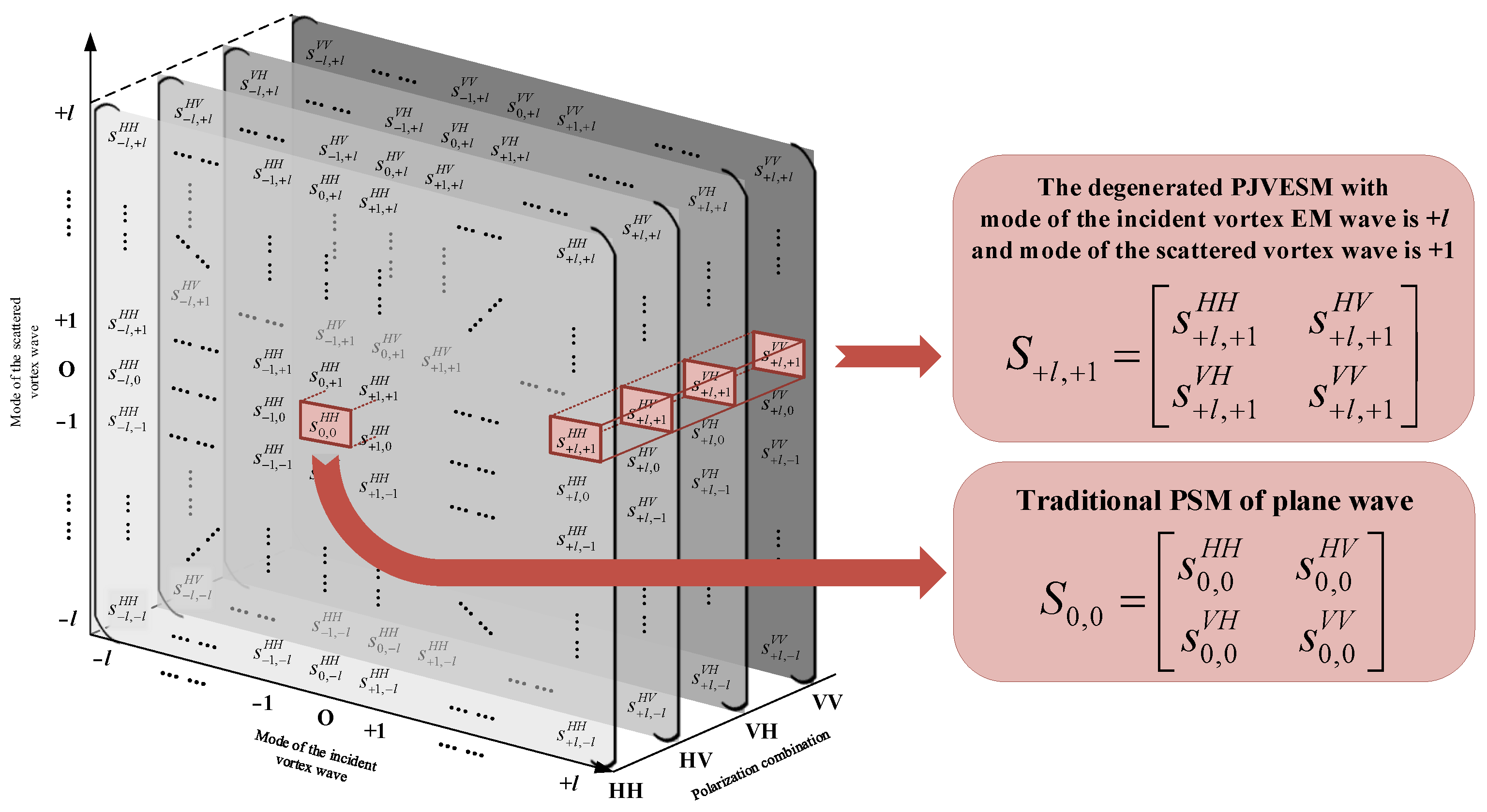
Matrix Degradation Form 1. Observe the matrix from the longitudinal direction. When the OAM modes of the incident and scattered waves of the vortex EM waves are fixed, the EVPJSM only contains four elements, corresponding to four SAM polarization combinations, respectively (Figure 4). According to the meanings of the coefficient in EVPJSM, these four elements can form a matrix whose form is similar to the traditional PSM, with the size of 2 × 2 . As a result, the EVPJSM will degenerate into the PSM S m , n , corresponding with the vortex EM wave with the incident wave mode of m and the scattered wave mode of n :
S m , n = s m , n H H s m , n H V s m , n V H s m , n V V ,
S m , n describes the target scattering characteristics when the vortex EM wave has a specific mode.
Matrix Degradation Form 2. In particular, when the incident and scattered modes of the vortex EM wave are both 0, its waveform will degenerate into a plane EM wave. Currently, the EVPJSM will degenerate into the traditional PSM, which is used to describe the target scattering characteristics of a plane wave:
S 0 , 0 = s 0 , 0 H H s 0 , 0 H V s 0 , 0 V H s 0 , 0 V V ,

5. Numerical Simulation and Discussion

5.1. Principle of Scattering Coefficient Calculation

From Section 4.1, it can be seen that the element s m , n X Y in the EVPJSM represents the target scattering coefficient of the incident field with mode m and the scattered field with mode n of the OAM under the SAM polarization combination of X Y . The coefficient is the ratio of the intensity of the vortex scattering field with mode n in OAM and Y-polarized in SAM to the vortex incident field with mode m in OAM and X-polarized in SAM:
s m , n X Y = E n s , X Y E m i , X Y
where E n s , X Y and E m i , X Y respectively represent the intensity of the scattered EM field with mode n and the incident EM field with mode m when the SAM polarization combination is X Y . s m , n X Y is dimensionless.

5.2. Experimental Setup

In this section, the EM simulation software Altair FEKO 2020 is selected to simulate and calculate the scattering coefficients of the EVPJSM for typical targets. Aiming at a certain SAM polarization combinations, the modes of the incident and scattered vortex EM wave are changed successively in the simulation experiment. The EM scattering problem is jointly solved by physical optics (PO) and the method of moments (MOM) to obtain the EVPJSM of the target backscattering of the OAM beams in the scattered field with mode +1 to +3 and the scattering field with mode 0 to +3 at microwave frequencies. The sphere and the flat plate of the perfect electric conductor (PEC) were selected as the test targets. Two SAM polarization combinations and twelve different OAM mode configurations are set for the transceiver antenna pairs in order to acquire each s m , n X Y in the EVPJSM. To cover all OAM-SAM combinations, 24 simulations were run for each target. Table 2 contains comprehensive simulation parameters as well as incident and scattered vortex EM field specifications.
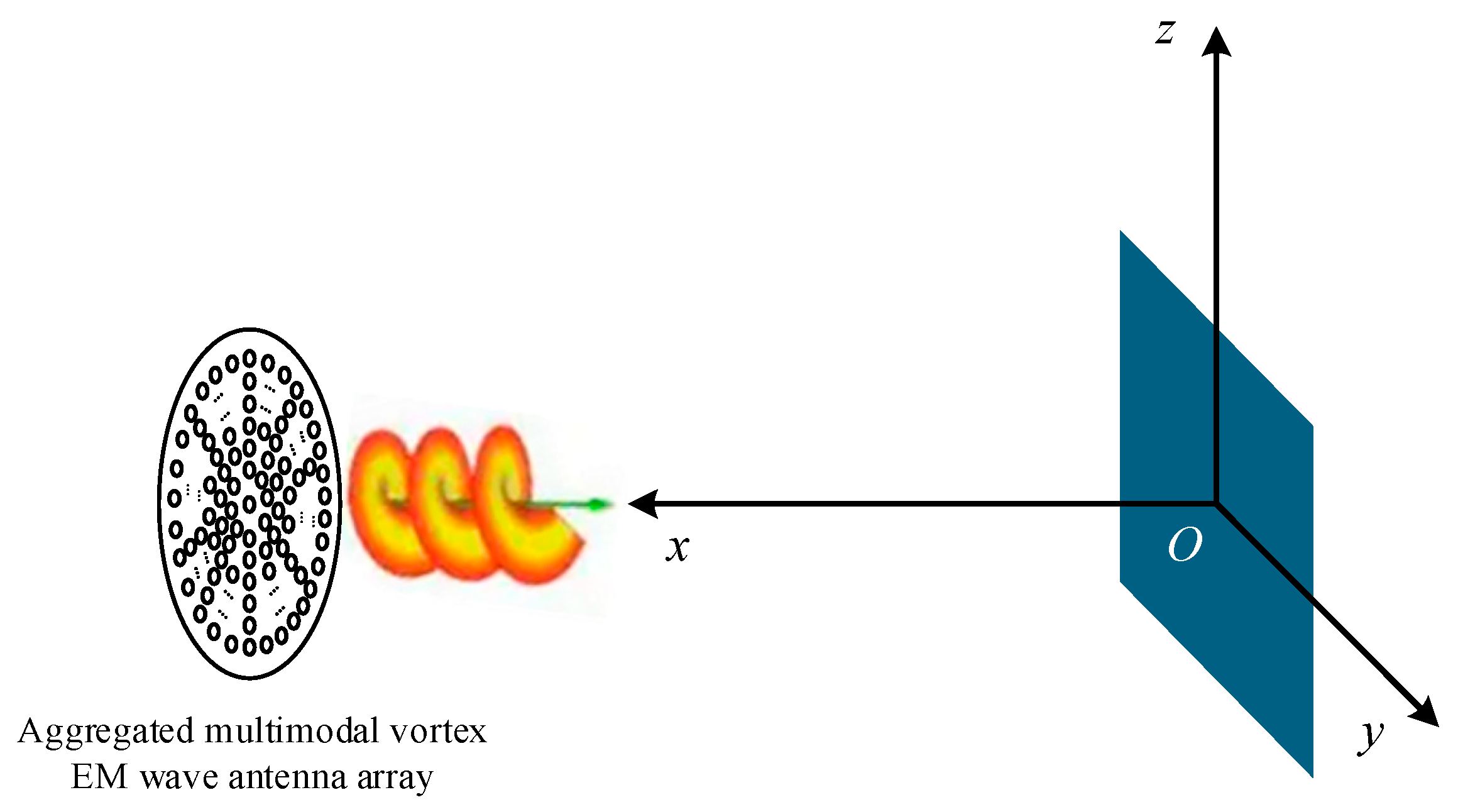
All of the vortex incident field data used in EM simulations derived from the research outcome of Project One of the National Key Research and Development Project “Long-Term High-Resolution Monitoring Technology of Vortex EM Wave Radar at Sea,” which is called the aggregated multimodal vortex EM wave antenna array. The antenna adopts the uniform circular array (UCA) form. The relevant parameters of the vortex incident field are shown in Table 3.
Notably, constrained by current system design limitations, the antenna system provides only H-polarized experimental vortex incident field data. Thus, this paper only simulates scattering coefficients for the SAM combinations HH and HV. Scattering coefficients s m , n X Y for VH and VV can be obtained through identical procedures, using the aforementioned configurations.

5.3. Calculation of the Vortex Scattering Coefficient of the PEC Sphere

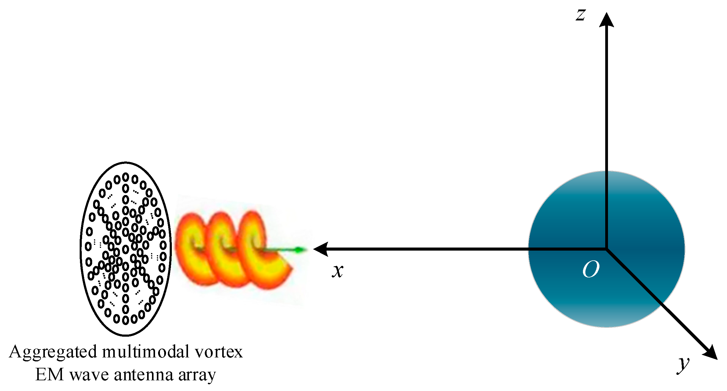
The radius of the PEC sphere is 0.25 m. A rectangular plane coordinate system is established, with the center of the sphere as the origin. The center of the vortex incident field is placed on the positive X-axis to align with the target center. The simulation scene of the sphere is shown in Figure 5.
The modes of the incident and scattered field are set in sequence. All the simulated results are written in Equations (11) and (12). The sphere’s scattering coefficients of the first two layers in EVPJSM are as follows:
S a m , s p h H H = s + 1 , + 3 H H s + 2 , + 3 H H s + 3 , + 3 H H s + 1 , + 2 H H s + 2 , + 2 H H s + 3 , + 2 H H s + 1 , + 1 H H s + 2 , + 1 H H s + 3 , + 1 H H s + 1 , 0 H H s + 2 , 0 H H s + 3 , 0 H H = 5.084 1.204 17.446 2.889 18.688 2.439 17.170 7.074 2.354 0.041 3.577 2.521 d B
S a m , s p h H V = s + 1 , + 3 H V s + 2 , + 3 H V s + 3 , + 3 H V s + 1 , + 2 H V s + 2 , + 2 H V s + 3 , + 2 H V s + 1 , + 1 H V s + 2 , + 1 H V s + 3 , + 1 H V s + 1 , 0 H V s + 2 , 0 H V s + 3 , 0 H V = 15.454 9.473 10.954 25.262 8.085 16.683 35.217 14.583 15.541 61.295 53.302 58.867 d B
Firstly, all the 24 values in the matrices (11) and (12) have to be converted into linear values. Then, the Min–Max method is applied for value normalization. All the values in S a m , s p h H H and S a m , s p h H V are normalized into these two new matrices:
S a m , s p h _ n o r H H = 0.004 0.018 0.751 0.026 1.000 0.024 0.705 0.031 0.023 0.014 0.031 0.024
S a m , s p h _ n o r H V = 0.000 0.002 0.001 0.000 0.002 0.000 0.000 0.001 0.000 0.000 0.000 0.000
The results show two of the layers of the EVPJSM. As shown in the simulation results, when the SAM polarization mode is HH, the PEC sphere’s scattering coefficients s + 1 , + 1 H H , s + 2 , + 2 H H , and s + 3 , + 3 H H are significantly higher in the same incident-scattered modes than those in different incident-scattered modes. This is due to the symmetry of the PEC sphere. The scattered waves have the same SAM polarization mode as the incident wave, which means the incident and scattered vortex EM waves in the same mode can achieve the best energy matching. Since the incident field in the simulation is derived from the measured data, there are a few cross-modal components in the simulated scattering field obtained. When the SAM polarization mode is HV, the scattering coefficient is extremely low, and very close to 0 (Equation (14)), which means the cross-polarization component is very low.
Moreover, the results conform to the description of Matrix Degeneration Form 1, as stated in Section 4.2. Focusing on the corresponding elements of matrices S a m , s p h _ n o r H H and S a m , s p h _ n o r H V , they can be degraded to the first-row elements of the sphere’s PSM:
S s p h = s m 0 , n 0 H H s m 0 , n 0 H V s m 0 , n 0 V H s m 0 , n 0 V V = 1 0 0 1
Consequently, the EVPJSM of the +1 to +3 mode OAM beam for a PEC sphere, obtained in this paper, describes the sphere’s scattering characteristics under vortex EM wave irradiation and can be mutually verified with the traditional sphere’s PSM.

5.4. Calculation of the Vortex Scattering Coefficient of the PEC Flat Plate

The side length of the PEC flat plate is 0.5 m. A plane rectangular coordinate system is established with the center of the flat plate as the origin. The center of the vortex incident field is placed on the positive X-axis to align with the target center. The simulation scene of the flat plate is shown in Figure 6.
The mode of the incident and scattered field are set in sequence. All the simulated results are written in Equations (16) and (17). The flat plate’s scattering coefficients of the first two layers in EVPJSM are as follows:
S a m , f l a t H H = s + 1 , + 3 H H s + 2 , + 3 H H s + 3 , + 3 H H s + 1 , + 2 H H s + 2 , + 2 H H s + 3 , + 2 H H s + 1 , + 1 H H s + 2 , + 1 H H s + 3 , + 1 H H s + 1 , 0 H H s + 2 , 0 H H s + 3 , 0 H H = 1.722 2.740 18.006 6.944 20.342 10.652 17.549 0.300 6.728 5.037 7.547 8.134 d B
S a m , f l a t H V = s + 1 , + 3 H V s + 2 , + 3 H V s + 3 , + 3 H V s + 1 , + 2 H V s + 2 , + 2 H V s + 3 , + 2 H V s + 1 , + 1 H V s + 2 , + 1 H V s + 3 , + 1 H V s + 1 , 0 H V s + 2 , 0 H V s + 3 , 0 H V = 16.956 9.844 11.363 22.451 9.238 15.419 28.162 12.862 16.128 67.168 46.970 58.623 d B
Repeat the normalization operation in Section 5.3. The normalization matrices S a m , f l a t _ n o r H H and S a m , f l a t _ n o r H V can be obtained:
S a m , f l a t _ n o r H H = 0.014 0.017 0.584 0.046 1.000 0.107 0.526 0.010 0.044 0.030 0.053 0.060
S a m , f l a t _ n o r H V = 0.000 0.001 0.001 0.000 0.001 0.000 0.000 0.001 0.000 0.000 0.000 0.000
The results show two of the layers of the EVPJSM. They are similar to the results of the PEC sphere. When the SAM polarization mode is HH, the PEC flat plate’s scattering coefficients s + 1 , + 1 H H , s + 2 , + 2 H H , and s + 3 , + 3 H H are significantly higher in the same incident-scattered modes than those in different incident-scattered modes. This proves that the incident and scattered vortex EM waves in the same mode can achieve the best energy matching. When the SAM polarization mode is HV, the scattering coefficient is extremely low, and very close to 0 (Equation (19)), which means the cross-polarization component is very low.
The results of flat plates conform to the description of Matrix Degeneration Form 1, as stated in Section 4.2. The corresponding elements of matrices S a m , s p h _ n o r H H and S a m , s p h _ n o r H V can be degraded to the first-row elements of the flat plate’s PSM:
S f l a t = s m 0 , n 0 H H s m 0 , n 0 H V s m 0 , n 0 V H s m 0 , n 0 V V = 1 0 0 1
In conclusion, the EVPJSM of the +1 to +3 mode OAM beam for a PEC flat plate describes its scattering characteristics under vortex EM wave irradiation and can be mutually verified with the traditional flat plate’s PSM.

6. Conclusions

Based on the orthogonal characteristics among different modes of multimodal vortex EM waves, this paper establishes a characterization relationship between the wave modes and target scattering characteristics, thereby constructing an EVSM. Subsequently, the PSM is integrated into the EVSM to form the EVPJSM. The EVSM and EVPJSM expand the unique observations of the OAM dimension of the vortex EM wave, achieving a multi-dimensional and refined description of the target scattering characteristics under such waves. The EM simulation is performed to acquire the two-layer elements within the EVPJSM for PEC spheres and flat plates under 12 pairs of OAM modes and two SAM polarization combinations at 10 GHz, offering examples for the characterization and quantitative measurement of target scattering characteristics in new dimensions. The simulation results suggest that these two matrices can reflect the new target scattering characteristics of the vortex EM wave, compared with the traditional PSM of spherical and flat plate targets. EVSM and EVPJSM will have important application values in multiple application fields, such as target characteristic measurement and extraction, and super-resolution imaging.
Future works include the simulated and experimental measurement of the target scattering characteristics of high-mode, combined targets, and multi-polarized vortex EM waves. These works aim to lay a theoretical foundation for the quantitative characterization and measurement of the target scattering characteristics.

7. Patents

Two patents were generated from this research. The publication numbers of the patents are No. CN117572377B and No. CN119471605B. Both of the patents can be accessed through the CNIPA Patent Search and Analysis System.

Author Contributions

Conceptualization and methodology, Z.Z. and Y.L.; software, Y.L.; validation, Y.L. and X.C.; investigation, X.C.; resources (incident field data), T.W.; data curation, Y.L.; writing—original draft preparation, Y.L.; writing—review and editing, Y.L. and Z.Z.; visualization, Y.L.; supervision, Z.Z.; project administration, Z.Z. All authors have read and agreed to the published version of the manuscript.

Funding

This research was funded by the National Key Research and Development Program of China (Grant No. 2022YFB3902400); and the National Natural Science Foundation of China (Grant No. 62301417).

Data Availability Statement

Data associated with this research are available and can be obtained by contacting the corresponding author.

Conflicts of Interest

The authors declare no conflicts of interest.

Abbreviations

The following abbreviations are used in this manuscript:
AMAngular Momentum
EMElectromagnetic
EVPJSMElectromagnetic Vortex-Polarization Joint Scattering Matrix
EVSMElectromagnetic Vortex Scattering Matrix
ISARInverse Synthetic Aperture Radar
LMLinear Momentum
OAMOrbital Angular Momentum
ORCSOAM Radar Cross Section
PSMPolarization Scattering Matrix
RCSRadar Cross Section
RFRadio Frequency
SAMSpin Angular Momentum
SARSynthetic Aperture Radar
VNAVector Network Analyzer

References

  1. Li, C.; Xu, H.; Peng, W.; Han, G.; Feng, X.; Liu, F.; You, D.; Wu, T.; Li, S. Research progress on vortex electromagnetic wave radar. China Basic Sci. 2023, 25, 44–53. [Google Scholar]
  2. Allen, L.; Beijersbergen, M.; Spreeuw, R.; Woerdman, J. Orbital angular momentum of light and the transformation of Laguerre-Gaussian laser modes. Phys. Rev. A 1992, 45, 8185–8189. [Google Scholar] [CrossRef] [PubMed]
  3. Garcés-Chávez, V.; McGloin, D.; Melville, H.; Sibbett, W.; Dholakia, K. Simultaneous micromanipulation in multiple planes using a self-reconstructing light beam. Lett. Nat. 2002, 419, 145–147. [Google Scholar] [CrossRef] [PubMed]
  4. Thide, B.; Then, H.; Sjoholm, J.; Palmer, K.; Bergman, J.; Carozzi, T.; Istomin, Y.; Ibragimov, N.; Khamitova, R. Utilization of photon orbital angular momentum in the low-frequency radio domain. Phys. Rev. Lett. 2007, 99, 087701. [Google Scholar] [CrossRef] [PubMed]
  5. Bu, X.; Zhang, Z.; Liang, X.; Zeng, Z.; Chen, L.; Tang, H. Scattering characteristics of vortex electromagnetic waves for typical targets. In Proceedings of the 2018 Asia-Pacific Microwave Conference (APMC), New York, NY, USA, 6–9 November 2018. [Google Scholar]
  6. Bu, X.; Liang, X.; Zhang, Z.; Chen, L.; Tang, H.; Zeng, Z. Scattering characteristics of vortex electromagnetic waves for a wedge. In Proceedings of the 2018 Progress in Electromagnetics Research Symposium (PIERS), Toyama, Japan, 26–30 August 2018. [Google Scholar]
  7. Guo, L.; Huang, Q.; Cheng, M.; Li, J.; Liu, S.; Cheng, M. The scattering of vortical electromagnetic waves by a coated sphere. In Proceedings of the 2018 IEEE International Symposium on Antennas and Propagation and USNC/URSI National Radio Science Meeting, New York, NY, USA, 8–13 July 2018. [Google Scholar]
  8. Liu, K.; Gao, Y.; Li, X.; Cheng, Y. Target scattering characteristics for OAM-based radar. AIP Adv. 2018, 8, 025002. [Google Scholar] [CrossRef]
  9. Liu, K.; Liu, H.; Sha, W.; Cheng, Y.; Wang, H. Backward scattering of electrically large standard objects illuminated by OAM beams. IEEE Antennas Wirel. Propag. Lett. 2020, 19, 1167–1171. [Google Scholar] [CrossRef]
  10. Fang, L.; Yan, J.; Zhou, L.; Yang, W.; Chen, B.; Lei, S. Analysis on Scattering Characteristics of an Electrically Large Ship under the Illumination of Vortex Electromagnetic Wave. In Proceedings of the 2022 International Conference on Microwave and Millimeter Wave Technology (ICMMT), Harbin, China, 15–18 August 2022. [Google Scholar]
  11. Arfan, M.; Ghaffar, A.; Alkanhal, M.; Naz, M.; Alqahtani, A.; Khan, Y. Orbital angular momentum wave scattering from perfect electromagnetic conductor (PEMC) sphere. Optik 2022, 253, 168562. [Google Scholar] [CrossRef]
  12. Bu, L.; Zhu, Y.; Chen, Y.; Yang, Y.; Zang, Y. Vortex-electromagnetic-wave-based ISAR imaging for high-speed maneuvering targets. Sci. Rep. 2022, 12, 18009. [Google Scholar] [CrossRef] [PubMed]
  13. Chen, X.; Li, H.; Wu, T.; Meng, X.; Li, F. Near-field electromagnetic scattering of Bessel vortex beam by metal target. Acta Phys. Sin. 2023, 72, 100302. [Google Scholar] [CrossRef]
  14. Wang, H.; Qu, T.; Niu, J.; Wu, J. Scattering Characteristics of Vortex Electromagnetic Waves by Symmetrical Targets. In Proceedings of the 2024 Photonics & Electromagnetics Research Symposium (PIERS), Chengdu, China, 21–25 April 2024. [Google Scholar]
  15. Sun, M.; Liu, S.; Guo, L. Scattering Field Intensity and Orbital Angular Momentum Spectral Distribution of Vortex Electromagnetic Beams Scattered by Electrically Large Targets Comprising Different Materials. Remote Sens. 2024, 16, 754. [Google Scholar] [CrossRef]
  16. Li, Y.; Li, M.; Cheng, X.; Wang, X. Summarization of radar polarization measurement modes. Syst. Eng. Electron. 2013, 35, 1873–1877. [Google Scholar]
  17. Wang, C.; Yu, W. Comparative analyses of Huynen target decomposition methods. J. Grad. Sch. Chin. Acad. Sci. 2011, 28, 402–409. [Google Scholar]
  18. Cloude, S.; Pottier, E. A review of target decomposition theorems in radar polarimetry. IEEE Trans. Geosci. Remote Sens. 1996, 34, 498–518. [Google Scholar] [CrossRef]
  19. Freeman, A.; Durden, S.L. A three-component scattering model for polarimetric SAR data. IEEE Trans. Geosci. Remote Sens. 1998, 36, 963–973. [Google Scholar] [CrossRef]
  20. Wang, X.; Zhou, S.; Zhao, W.; Peng, X.; Ma, H. Target polarization scattering matrix estimation with conformal MIMO radar. Signal Process. 2023, 210, 109054. [Google Scholar] [CrossRef]
  21. Ciuca, M.; Vasile, G.; Anghel, A.; Gay, M.; Ciochina, S. Real Representation of the Polarimetric Scattering Matrix for Monostatic Radar. Remote Sens. 2023, 15, 1037. [Google Scholar] [CrossRef]
  22. Malik, R.; Singh, G.; Dikshit, O.; Yamaguchi, Y. Model-Based Nine-Component Scattering Matrix Power Decomposition. IEEE Geosci. Remote Sens. Lett. 2024, 21, 4008105. [Google Scholar] [CrossRef]
  23. Maurya, H.; Bhattacharya, A.; Mishra, A.; Panigrahi, R. Hybrid Three-Component Scattering Power Characterization from Polarimetric SAR Data Isolating Dominant Scattering Mechanisms. IEEE Trans. Geosci. Remote Sens. 2022, 60, 4415315. [Google Scholar] [CrossRef]
  24. Bu, X. Research on Synthetic Aperture Radar Technology Based on Vortex Electromagnetic Waves. Ph.D. Thesis, University of Chinese Academy of Sciences, Beijing, China, 2019. [Google Scholar]
  25. Yao, A.; Padgett, M. Orbital angular momentum: Origins, behavior and applications. Adv. Opt. Photonics 2011, 3, 161–204. [Google Scholar] [CrossRef]
  26. Zhang, Y.; Dong, X.; Yu, L.; Zhao, X.; Zhang, Y.; Shi, X.; Li, D.; Yang, Q.; Kang, X.; Zhai, W.; et al. Modern Radar Theory and Technology, 2nd ed.; Science Press: Beijing, China, 2023; pp. 42–46. [Google Scholar]
  27. Mahafza, B.; Elsherbeni, A. MATLAB Simulations for Radar Systems Design, 11th ed.; Electronic Industry Press: Beijing, China, 2016; pp. 345–346. [Google Scholar]
Figure 1. Wavefront of vortex electromagnetic waves of mode 0 to +3 [25]. (a) Vortex EM wave of mode 0; (b) Vortex EM wave of mode +1; (c) Vortex EM wave of mode +2; (d) Vortex EM wave of mode +3.
Electronics 14 03346 g001
Figure 2. Expressions of EVSM.
Electronics 14 03346 g002
Figure 3. Expressions of EVPJSM.
Electronics 14 03346 g003
Figure 4. Schematic diagram of the degradation problem of the EVPJSM.
Electronics 14 03346 g004
Figure 5. Simulation scene of the sphere.
Electronics 14 03346 g005
Figure 6. Simulation scene of the flat plate.
Electronics 14 03346 g006
Table 1. Correspondence between EVSM, incident-scattered waves modes and representation regions.
Number of the Planar AreaSubmatrix Symbolic RepresentationLocated QuadrantMode of
Incident Wave
Mode of
Scattered Wave
I S v 1 Quadrant IPositive mode (+)Positive mode (+)
II S v 2 Quadrant IINegative mode (−)Positive mode (+)
III S v 3 Quadrant IIINegative mode (−)Negative mode (−)
IV S v 4 Quadrant IVPositive mode (+)Negative mode (−)
Table 2. Simulation parameters and specifications of the incident and scattered vortex EM fields.
Name of ParameterValue
Distance between antennas and target5 m
OAMMode of incident fields+1, +2, +3
Mode of scattered fields0, +1, +2, +3
Mode combinations in simulation
[ m , n ]
[+1, 0], [+1, +1], [+1, +2], [+1, +3],
[+2, 0], [+2, +1], [+2, +2], [+2, +3],
[+3, 0], [+3, +1], [+3, +2], [+3, +3]
SAMPolarization of incident fieldsH
Polarization of scattered fieldsH, V
Polarization combinations in simulation
[ X , Y ]
[H, H], [H, V]
Table 3. Relevant parameters of the vortex incident field.
Name of ParameterValue
Center frequency10 GHz
SAM polarization modeHorizontal polarization (H)
Field size0.4 m × 0.4 m
Sampling points of the field41 × 41
OAM mode+1, +2, +3
Disclaimer/Publisher’s Note: The statements, opinions and data contained in all publications are solely those of the individual author(s) and contributor(s) and not of MDPI and/or the editor(s). MDPI and/or the editor(s) disclaim responsibility for any injury to people or property resulting from any ideas, methods, instructions or products referred to in the content.