Abstract
Harmonic distortion from non-linear loads poses a significant challenge to power quality in residential nanogrids, often requiring complex control strategies and communication between distributed resources. This paper presents a parallel hybrid inverter system for an AC nanogrid that enhances power quality using only decentralized droop-based primary control, without the need for secondary control or communication links. The system features two inverters with strategic placement: one maintains voltage stability at the point of common coupling, while the other directly supplies the harmonic and reactive current demanded by non-linear loads. A compensation mechanism allows the second inverter to dynamically switch from supplying sinusoidal current to injecting targeted harmonic components, effectively isolating distortion from the main grid. Simulation results confirm that this approach significantly reduces voltage distortion at the PCC and ensures balanced power sharing, all while simplifying the control architecture. The proposed method offers a scalable, cost-effective solution for residential nanogrids seeking to integrate diverse loads and distributed energy resources while maintaining high power quality.
1. Introduction
The rapid integration of renewable energy resources has accelerated the adoption of voltage source converters (VSCs) in modern power systems, increasing interest in grid-forming (GFM) converter technology [1]. Unlike grid-following (GFL) converters, which use phase-locked loops (PLLs) to synchronize as current sources, grid-forming converters act as controlled voltage sources. They autonomously establish and regulate voltage amplitude and frequency at the point of common coupling (PCC), even without a strong external grid [2,3]. GFM converters maintain stable operation in weak or islanded grids, where GFL converters may struggle due to their reliance on external voltage references [2]. While much research has addressed GFM converters in microgrid applications, the requirements and operational context of nanogrids are distinctly different. Nanogrids typically have lower capacity, highly localized loads, and limited geographic extent compared to microgrids. These characteristics introduce unique challenges and opportunities, especially in residential settings where reliability, simplicity, and cost effectiveness are critical [2,3].
GFM converters introduce challenges related to power quality and system dynamics. In islanded microgrids, interactions between converter filters, line impedances, and diverse loads can create resonance points, affecting performance [3]. These resonance phenomena, influenced by passive filters, line parameters, and non-linear or constant power loads, may cause stability issues if not managed [3]. Advanced control strategies and careful system design are needed to ensure robust operation [1,3].
In many residential nanogrid implementations, inverters are sized for peak generation. For much of the day, the PV array produces less power than the inverter’s capacity, leaving some current-handling capability unused [1,3,4]. This unused margin can be used for grid support functions, such as reactive power compensation and harmonic current mitigation at the PCC [4]. The inverter can operate as both a grid interface and an active power filter to counteract non-linear loads.
Hybrid inverter solutions are proving increasingly important for flexible energy management in residential nanogrids. These inverters integrate solar generation, battery storage, and grid connectivity, allowing efficient energy management [1,2,3,5]. Recent PWM improvements have contributed to grid stability and reduced harmonic distortion. Challenges remain, including long-term reliability and scalability, especially as energy demands and grid conditions change [2,5].
Most power quality improvement strategies in distributed energy systems, including nanogrids, are still borrowed from the microgrid literature and implemented at the secondary control layer, which can add unnecessary complexity for small-scale, localized systems. Microgrids face challenges such as voltage and frequency regulation, power sharing, and managing power exchange with the utility [6,7]. Hierarchical control structures are common, with primary control for local inverters, secondary for coordination and restoration, and sometimes tertiary for broader grid integration [8,9,10]. The effectiveness of secondary control depends on reliable communication networks [11]. This dependence makes systems vulnerable to communication delays and data loss [12]. However, residential nanogrids benefit more from decentralized control strategies at the primary level, where the absence of a communication infrastructure simplifies implementation and improves robustness. There is a growing preference for decentralized control strategies at the primary and secondary levels to reduce reliance on communication networks and improve security [13].
The widespread use of power electronic devices has increased challenges related to current harmonics. Non-linear loads demand non-sinusoidal currents and reactive power, causing voltage distortion at the PCC and affecting all users at the node [14]. Shunt active power filters (APFs) are effective for supplying the reactive power and harmonic currents required by non-linear loads through advanced closed-loop control strategies [15,16]. Many control schemes have been proposed for APFs [17]. Most studies focus on single-inverter APF topologies, with limited research on parallel hybrid inverter topologies, which could combine efficient power sharing and harmonic compensation [16].
However, conventional single-inverter active power filter (APF) topologies face inherent limitations, such as limited current handling capacity, reduced harmonic compensation effectiveness, and increased stress on inverter components when dealing with varying non-linear loads [15,17]. These constraints can lead to diminished filtering performance and potential inverter reliability issues, especially in residential nanogrids with diverse load profiles [15]. Parallel hybrid inverter configurations mitigate these issues by distributing harmonic compensation tasks among multiple inverters, enhancing overall harmonic mitigation capability, reducing individual inverter burden, and improving system scalability and fault tolerance [16,18]. Additionally, combining a 2-level VSI focused on voltage stability with a multi-level inverter dedicated to harmonic compensation enables the effective separation of power sharing and power quality operations without increasing control complexity [16,19]. This structure isolates harmonic currents locally and supports robust residential and commercial power systems.
While droop control is widely recognized for its decentralized operation and fundamental role in microgrid stability and power sharing, much of recent research has concentrated on hierarchical multi-layer control schemes involving secondary and tertiary layers to enhance performance, restore nominal values, and optimize energy management. Refs. [20,21] present sophisticated hierarchical and decentralized droop control methods that improve power sharing accuracy and voltage/frequency regulation, but these come with increased system complexity, communication dependencies, and costs. Similarly, ref. [22] showcases adaptive, learning-based droop control approaches that enhance dynamic response but require significant computational resources. Despite these advances, there remains a notable scarcity of focused research on primary droop control in isolation, which continues to offer substantial advantages such as simplicity, communication-less operation, fast dynamic response, and robust power sharing, particularly suited for smaller or residential nanogrids. Studies like [23,24] emphasize the viability and stability of primary-only droop control solutions without secondary or tertiary layers. The work in [24] highlights how dismissing high-bandwidth communication and secondary controls simplifies the system while maintaining stability through a simple power-to-voltage droop strategy, validated in DC nanogrid contexts. This paper contributes to filling the research gap on the effectiveness of primary droop control alone, supporting simpler approaches in microgrid management that balance performance with feasibility, especially in low-cost, communication-constrained environments.
Droop control remains the predominant decentralized technique for power sharing in inverter-based microgrids due to its simplicity and communication-free operation. However, its application under non-linear load conditions reveals inherent contradictions such as power sharing deviations and harmonic amplification, which negatively impact power quality and system stability [25,26]. These issues arise because non-linear loads induce unbalanced currents and harmonics that interact with droop controller dynamics, causing voltage distortion and load mismatch [25]. Although hierarchical and adaptive droop control methods have been proposed to mitigate these drawbacks [20,21,22], they often increase system complexity and rely on communication infrastructure, which can be costly and less robust for residential nanogrids. Consequently, the recent literature highlights the need for simplified control approaches that retain the benefits of primary droop control while addressing power sharing and harmonic challenges [23,24]. This motivates the present study’s focus on a primary droop control scheme integrated with harmonic compensation to deliver a reliable, low-complexity solution suitable for residential nanogrids.
Studies focusing on primary droop control integrated with harmonic mitigation techniques, such as for DC nanogrids and ref. [24] for AC microgrids, ref. [23] validate rapid dynamic responses with power sharing errors typically below and notable reductions in total harmonic distortion (THD) exceeding compared to unmitigated systems. The study in [23] highlights that primary droop control strategies, especially when combined with virtual impedance and harmonic compensation, provide a practical balance of simplicity, communication-less operation, and robust power sharing performance suitable for islanded microgrids. These findings highlight the advantage of eliminating secondary control layers and communication reliance, which not only simplifies system architecture but also enhances robustness and fault tolerance in residential and small-scale distributed power systems.
Table 1 summarizes existing inverter control approaches and topologies relevant to residential and nanogrid applications. It compares control strategies, harmonic handling capabilities, inverter types, and communication dependencies. Unlike hierarchical and communication-dependent methods shown, the proposed system uniquely integrates a simple yet effective primary droop control scheme with a parallel hybrid inverter topology that directly addresses harmonic compensation at the non-linear load. This configuration enables communication-less operation while maintaining power quality and dynamic performance.

Table 1.
Comparison of existing inverter control strategies, topologies, harmonic handling, and communication requirements.
This paper addresses the unique operational needs of residential nanogrids and presents a novel parallel hybrid inverter system specifically designed for these localized energy networks to enhance power quality and mitigate harmonic distortion from non-linear loads. The main contributions are the following:
- The proposed system is tailored to residential nanogrid applications, operating entirely on primary droop control and eliminating reliance on secondary or tertiary control layers and communication infrastructure which is a critical advantage for small-scale, autonomous systems.
- The architecture uses a 2-level voltage source inverter (2L VSI) for voltage stability at the PCC, and a 3-level T-type inverter (3L T-type) that is strategically connected directly to the non-linear load. This novel configuration allows the T-type inverter to participate in both active power sharing and harmonic compensation, supplying the required current and harmonic components to non-linear loads. This approach isolates harmonic pollution at the PCC, maintaining sinusoidal voltage and current.
2. System Description
2.1. Power System
The proposed AC nanogrid system is designed with two inverters connected in parallel, forming a parallel hybrid inverter architecture. The first inverter is a conventional 2-level voltage source inverter (2L VSI). This topology is widely used due to its simple structure, ease of control, and cost effectiveness, making it suitable for supplying the fundamental load current and supporting voltage stability at the point of common coupling (PCC). The second inverter is a 3-level T-type inverter (3L T-type), which offers several advantages over traditional 2-level and even other multilevel inverters. The 3L T-type inverter is known for its improved efficiency, reduced switching losses, and superior harmonic performance. By generating output voltages with more levels, it significantly reduces total harmonic distortion (THD) and electromagnetic interference, making it ideal for applications where power quality is a priority [4,30,31]. Figure 1 illustrates the schematic of the proposed AC nanogrid, showing the parallel connection of the 2L VSI and the 3L T-type inverter, as well as the placement of loads and points of interconnection.
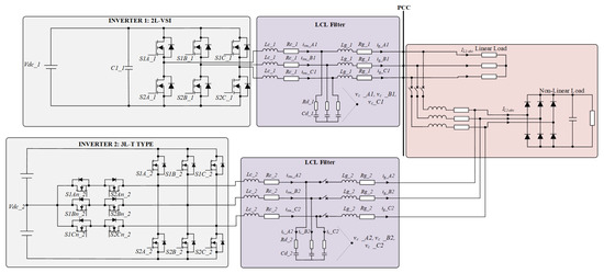
Figure 1.
Schematic diagram of the proposed AC nanogrid with parallel hybrid inverter system.
From a residential nanogrid perspective, the hybrid combination of a 2L VSI and a 3L T-type inverter offers a balanced and practical solution that meets both cost and power quality requirements. The simplicity and low cost of 2L VSI makes it well-suited to supply fundamental active power and maintain voltage stability, aligning with typical residential inverter sizing and budget constraints. Conversely, the 3L T-type inverter excels in harmonic suppression and efficiency due to its multi-level voltage output capability, making it highly effective at mitigating distortion caused by non-linear loads prevalent in residential environments. This hybrid arrangement reduces overall costs compared to a dual 3L T-type inverter setup, while achieving lower harmonic distortion and switching losses than dual 2L VSI systems. Additionally, by distributing the fundamental power delivery and harmonic compensation tasks between the two specialized inverters, the system simplifies control strategies and enhances reliability, which are critical considerations for residential nanogrids.
A key feature of this system is the strategic placement of the 3L T-type inverter. Unlike conventional setups, the 3L T-type inverter is directly connected to the non-linear load. The main idea behind this connection is the dedication of the 3L T-type inverter to supply the harmonics and reactive current demanded by the non-linear load, through which the system can effectively isolate harmonic pollution at the PCC. The strategic placement of the 3L T-type inverter is illustrated in Figure 2.
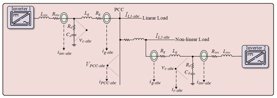
Figure 2.
Connection scheme of parallel hybrid inverter system.
2.2. Control System
The control scheme of each inverter of the nanogrid system is illustrated in Figure 3. Here, 2L VSI is referred to as Inverter 1 and 3L T-type as Inverter 2. The filter output current and output voltage of inverters are denoted by and , denotes the output current of the inverter, is the estimated LCL filter current, and represents the compensation current from the harmonic strategy.
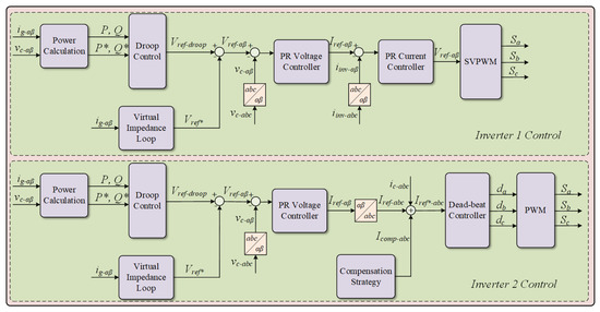
Figure 3.
Control scheme of AC nanogrid system.
2.2.1. Droop Control
In this work, only primary droop control is implemented, without any secondary or tertiary control layers. This exclusive use of primary control greatly simplifies the system architecture and eliminates the need for complex communication infrastructure. As a result, the proposed approach enhances reliability and reduces both cost and vulnerability to communication failures or cyber threats. Furthermore, the absence of higher-level control layers ensures faster dynamic response and improved system efficiency, making the solution highly practical for real-world residential nanogrids.
Once the 3L T-type inverter is to be connected in the system, the control system activates an enable signal. After the enable control signal is activated, the inverter’s reference angle and voltage are determined by the droop equations, which adjust the output based on the measured active and reactive power. This approach ensures a smooth and reliable connection of the 3L T-type inverter to the nanogrid and enables stable, communication-free power sharing with the other inverter. A schematic diagram of the droop control implementation for this system is shown in Figure 4.

Figure 4.
Droop control scheme for AC nanogrid system.
The frequency/voltage droop control equations are described below:
Here, and are the nominal angular frequency and voltage for the system, while and V are the actual measured values. P and Q denote the instantaneous active and reactive power output, and and are their respective setpoints. The parameters and represent the droop gains for frequency and voltage, respectively, and are calculated as
where and are the maximum permissible active and reactive power outputs of the inverter. and are the largest allowable deviations in frequency and voltage, respectively.
The droop control parameters used in the simulation are determined based on realistic inverter ratings and allowable system variations to ensure stable and effective power sharing. The active and reactive power references, = 5000 W and = 1500 VAR, correspond to the rated capacity of the inverters within the nanogrid. The allowable frequency deviation, , is set to of the nominal system frequency (50 Hz), resulting in . The voltage deviation, , is maintained at of the nominal voltage (230 V), i.e., .
The selection of droop control parameters is based on standard grid code requirements and inverter capability limits. According to EN 50160 [32], the frequency in low-voltage distribution systems should not deviate by more than of its nominal value, and the voltage should remain within [33]. Therefore, and are set according to these standards to ensure grid code compliance and system stability under typical operational disturbances. The maximum power values, and , are determined based on the rated apparent power of the inverter units. In this system designed for a total power demand of 10 kW, with two equally rated inverters sharing the load, each inverter’s maximum power is set to 5 kW, reflecting its maximum continuous output capability. This ensures that the droop gains are appropriately scaled to the inverter ratings and prevent overloading under any operating condition. The droop coefficients ( and ) directly influence system frequency and voltage stability, as well as the power sharing ratio between parallel inverters.
2.2.2. Virtual Impedance Loop
To enhance the stability and power sharing accuracy of the parallel inverter system, a virtual impedance loop is integrated into the voltage reference generation, following the approach in [34]. The virtual impedance is implemented by modifying the voltage reference which is proportional to the inverter’s output current in the stationary reference frame:
where and are the virtual resistance and inductance parameters, respectively. Here, and represent the modified voltage reference components, while and are the inverter output current components in the frame.
The virtual impedance parameters and critically affect the power-sharing accuracy and stability of parallel inverter operation. In this work, the virtual impedance values are selected following the established stability criteria to mitigate circulating currents among inverters and improve robustness against load variations and harmonics. Specifically, and are tuned to provide sufficient damping to the inverter output current dynamics without excessively increasing voltage drop or limiting power capability. The parameter design methodology aligns with the stability analyses presented in the key literature [35,36], in which the appropriate virtual impedance selection that can decouple inverter interactions and improve sharing of both active and reactive power under unbalanced or non-linear load conditions is demonstrated.
Simulation-based tuning is employed to validate and fine-tune and , ensuring the closed-loop system exhibits no adverse oscillations or power sharing deviations under typical residential non-linear load scenarios. The tuning procedure also considers EN 50160 [32] voltage and frequency deviation limits [33] to maintain power quality and grid code compliance.
2.2.3. Proportional-Resonant Controller
The general structure of a PR controller is designed to provide high gain at a target frequency, enabling effective tracking of sinusoidal references and robust disturbance rejection [37].
For the design and tuning of the PR controllers, a discretization approach is adopted to ensure implementation on digital devices that operate in discrete time domain, following the methodology outlined in [38]. Controller parameters are determined using MATLAB’s SISOTOOL (MATLAB R2021a, The MathWorks Inc., Natick, MA, USA), which allows for gain selection and stability assessment in the discrete domain. The PR controller’s transfer function is discretized using the Tustin method with pre-warping to preserve frequency response characteristics, whereas the plant’s transfer functions are discretized using First Order Hold (FOH) method. The resulting discrete-time form for the PR controller is used for digital implementation. The resulting discrete-time form for the PR controller is
where is the sampling period, and is the resonant frequency.
The tuning of the proportional and resonant gains for the current and voltage PR controllers is based on specific dynamic performance requirements. For the current PR controller, the design objectives include a settling time of less than 0.1 s, rise time below 0.05 s, and overshoot less than . Using this approach, gains of and are determined, ensuring fast and accurate current tracking suitable for inverter output current regulation. Similarly, for the voltage PR controller, the design targets a settling time under 0.2 s, rise time less than 0.1 s, and overshoot below . With these criteria, gains of and are selected to provide stable voltage regulation with adequate dynamic response. The difference in gain magnitudes reflects the need for the current control loop to respond faster than the voltage loop, ensuring precise control of output current references.
The stability and robustness of the cascaded voltage and current control loops using these gains are validated through Bode and Nyquist analyses performed in SISOTOOL and are shown in Figure 5 and Figure 6. The Bode magnitude plot exhibits a sharp peak at the resonant frequency (50 Hz or 314 rad/s), confirming the infinite gain at this frequency for accurate sinusoidal reference tracking. The phase margin exceeds 45 degrees, indicating sufficient stability margin. The Nyquist plot confirms closed-loop stability, as the response does not encircle the critical point (−1, 0). These analyses confirm that the chosen gains meet the stability criteria and dynamic performance expectations under varying operating conditions.
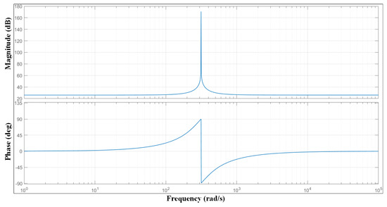
Figure 5.
Bode plot for the cascaded control system.
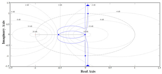
Figure 6.
Nyquist diagram for the cascaded control system.
2.2.4. Deadbeat Current Control for 3L T-Type Inverter
For the 3L T-type inverter, a deadbeat current controller is used instead of a traditional PR current controller, due to its effectiveness in harmonic mitigation and reactive current support for non-linear loads. Deadbeat control operates in the discrete-time domain, using a predictive model to drive the output current to its reference in a single sampling interval [39,40].
The controller is implemented as described in [4]. Although separate equations can be used for the positive and negative half-cycles to account for slight voltage differences, in this work, a single unified equation is implemented for the deadbeat controller. This simplification is justified by the relationship = = , as mentioned in [4], which is valid for balanced DC bus voltages in the T-type inverter. The reference current input is the sum of the PR voltage controller output , the estimated LCL filter current , and the compensation current from the harmonic strategy as shown in Figure 3. The duty cycle is given by
The unified deadbeat control expression used in this study assumes a balanced DC link and holds accurately under normal operating conditions. In cases of DC voltage imbalance or severe grid disturbances, deviations between and may occur, causing the simplified expression to introduce slight inaccuracies. Under such conditions, the control can be refined by separately calculating the positive and negative half-cycle duty cycles to account for these voltage differences. Nevertheless, for the scope of this work, focusing on typical nanogrid operation with controlled DC bus voltage and moderate disturbances, the simplified deadbeat controller achieves sufficiently accurate current tracking and effective harmonic mitigation.
2.2.5. Compensation Strategy
To enable the 3-level T-type inverter to supply the harmonics and reactive current demanded by non-linear loads, a compensation strategy is implemented as described in [41]. The compensation current is determined as the difference between the measured load current and its fundamental positive-sequence component, and a limiting mechanism ensures the inverter operates within its rated capacity:
where is the load current being provided to non-linear load, and is the extracted positive sequence component of the load current.
A synchronous reference frame (SRF) transformation is used to extract the fundamental positive-sequence component from the load current, utilizing the phase angle obtained from the grid voltage. The resulting compensation current thus targets all harmonic content as well as any unbalanced (negative and zero-sequence) components, enabling the inverter to operate as an effective active power filter.
To prevent the inverter from exceeding its rated current, the compensation strategy includes a limiting mechanism. The RMS value of the compensation current, , is calculated based on the inverter’s nominal current and the RMS values of the currents allocated for active and reactive power control:
where is the inverter’s rated RMS current, and and are the RMS values of the reference currents for active and reactive power, respectively.
To ensure the T-type inverter does not exceed its safe operating limits while compensating for harmonics and unbalanced currents, a current limitation mechanism is applied within the compensation strategy [41]. After calculating the compensation current as the difference between the measured load current and its fundamental positive-sequence component, the root mean square (RMS) value of this compensation current is compared to the maximum allowable compensation current, which is determined by the inverter’s available capacity. If the estimated compensation current, , is less than or equal to the maximum limit, , the unmodified compensation current is used. However, for the case where the compensation current exceeds the capacity, it is scaled down, ensuring that the inverter only supplies as much compensation as it can safely handle. This process dynamically determines how much of the inverter’s capacity is allocated for harmonic compensation, allowing the system to maximize power quality improvement at the PCC without risking inverter overload [41]:
By implementing this current limitation, the T-type inverter is able to isolate harmonic pollution from the grid while always operating within its rated capacity, maintaining both reliability and effective harmonic mitigation.
A schematic representation of the compensation strategy is shown in Figure 7. The compensation strategy is implemented through an activation signal once the 3L T-type inverter is connected in the system.
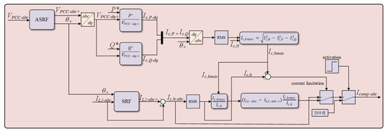
Figure 7.
Block diagram of compensation strategy for generation of compensation current.
3. Simulation Results
The performance of the proposed parallel hybrid inverter system (Figure 1) is evaluated using PLECS. Each inverter is modeled with its dedicated control scheme as described previously. The key simulation parameters are given in Table 2.

Table 2.
Nominal values of AC nanogrid components.
The simulation is divided into four stages to demonstrate the effect of non-linear loads and the effectiveness of the compensation strategy.
3.1. Stage A
Initially, the 2L VSI supplies only a linear load. The voltage and current at the PCC are purely sinusoidal (Figure 8), confirming that the control system maintains excellent power quality under linear loading. This stage establishes the baseline performance of the system.
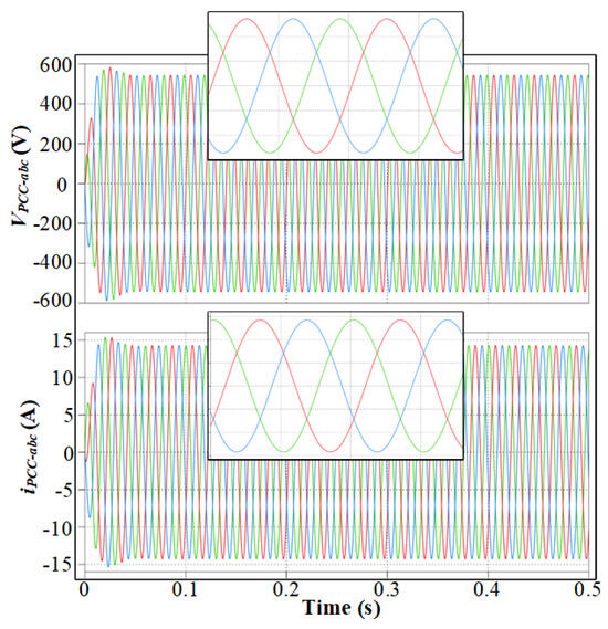
Figure 8.
Three-phase PCC voltage and current with Inverter 1 (2L VSI) supplying a linear load.
3.2. Stage B
A non-linear load is introduced at 0.5 s. The PCC voltage and current waveforms, shown in Figure 9, show clear distortion, with increased harmonic content due to the non-linear load. This demonstrates how non-linear loads degrade power quality, emphasizing the need for harmonic mitigation.
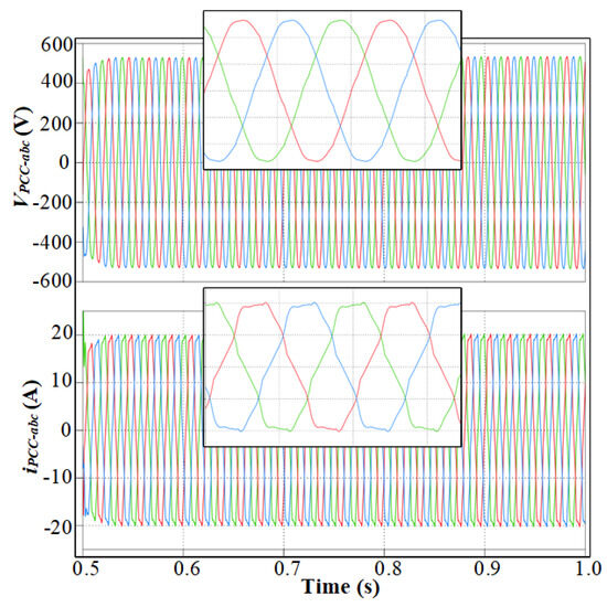
Figure 9.
Three-phase PCC voltage and current with Inverter 1 (2L VSI) supplying a linear and non-linear load.
3.3. Stage C
At 1 s, the 3L T-type inverter is connected in parallel, interfacing directly with the non-linear load. However, its harmonic compensation strategy is not yet activated. Figure 10 shows the overall system behavior during Stage C from 1 s to 3 s, illustrating persistent distortion in the PCC voltage and current despite the increased inverter capacity. Figure 11 presents a zoomed-in view of the interval from 2 s to 2.5 s, highlighting the detailed waveform distortion during this period. These results confirm that merely connecting the additional inverter does not mitigate harmonic pollution unless its compensation control is engaged.
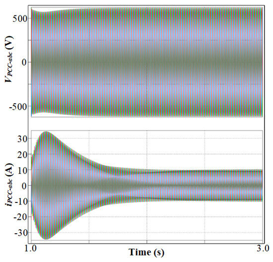
Figure 10.
Three-phase PCC voltage and current during full Stage C (1 s to 3 s).
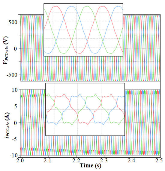
Figure 11.
Three-phase PCC voltage and current during parallel operation of Inverter 1 (2L VSI) and Inverter 2 (3L T-type) without active compensation.
3.4. Stage D
At 3 s, the compensation strategy for the 3L T-type inverter is activated. Inverter 2 now supplies both the harmonic and reactive current demanded by the non-linear load. As a result, the PCC voltage and current return to undistorted, sinusoidal waveforms, illustrated in Figure 12, demonstrating the effectiveness of the compensation strategy in restoring power quality. This demonstrates the success of the compensation algorithm in isolating harmonic pollution at the source and restoring power quality at the PCC. The strategic placement of the 3L T-type inverter, being directly connected to the non-linear load, enables this selective compensation, while Inverter 1 (2L VSI) continues to supply only the linear load. Consequently, the PCC is shielded from the adverse effects of harmonic currents, and both voltage and current at the PCC remain undistorted and in-phase.
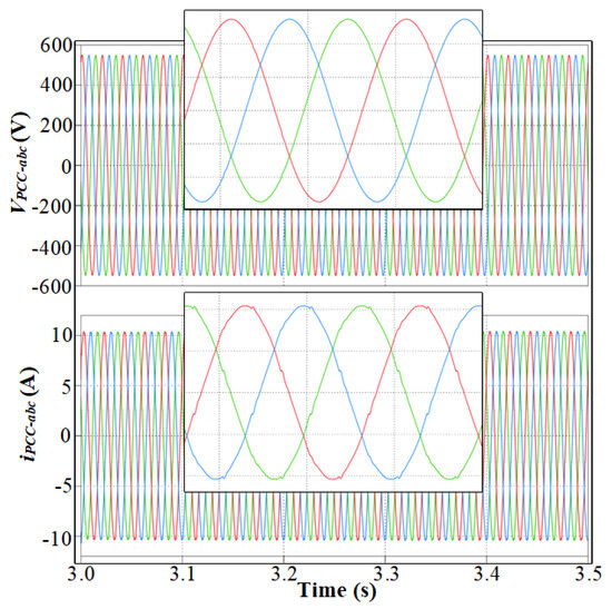
Figure 12.
Three-phase PCC voltage and current after activation of compensation strategy.
To further illustrate the operation of the compensation strategy, Figure 13 presents the output current of Inverter 2. Before compensation, the current is sinusoidal; after activation, it becomes non-sinusoidal, indicating that Inverter 2 is now providing the required harmonics for the non-linear load. The active power sharing graph, shown in Figure 14, provides a clear picture of how the load is distributed between the two inverters during the simulation. From 0 s to 0.5 s, only the linear load is connected with a demand of 8 kW, and Inverter 1 supplies the entire load. At 0.5 s, a 2 kW non-linear load is applied in parallel, increasing the total load demand to roughly 10 kW. However, in practice, due to the dynamic response of the control loops and possible brief inrush effects from the non-linear load, the measured power output of Inverter 1 temporarily rises above the expected 10 kW, peaking between 10 kW and 12 kW. This transient overshoot is typical in such scenarios as the single inverter instantaneously compensates for the entire load step before the new steady state is established [42]. At 1 s, Inverter 2 is brought online. Rather than an abrupt division, the power sharing between Inverter 1 and Inverter 2 transitions gradually. This is accomplished through the primary droop control mechanism, enabling smooth synchronization and load redistribution without instabilities or circulating currents [43]. During this period (1 s to 2 s), the output of Inverter 1 decreases steadily as Inverter 2 ramps up, both eventually converging to supply equal shares of the total load. By approximately 2 s, both inverters achieve balanced sharing, each supplying 5 kW (half the total 10 kW load), which corresponds to their rated continuous power. This coordinated operation ensures balanced power delivery and improved power quality at the PCC.
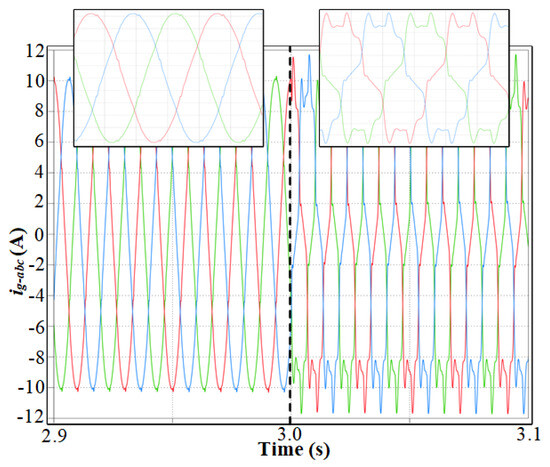
Figure 13.
Three-phase output current of Inverter 2 (3L T-type).
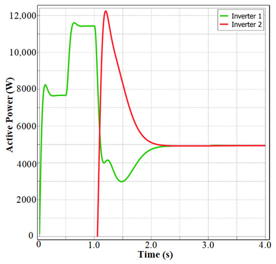
Figure 14.
Active power sharing between 2L VSI and 3L T-type inverters.
Figure 15 summarizes the PCC voltage and current over the entire simulation period, clearly showing the transition from clean to distorted waveforms and back to clean operation after compensation is enabled.
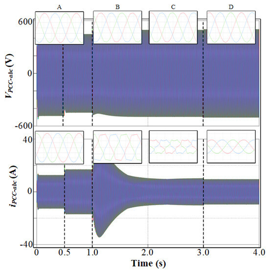
Figure 15.
Three-phase PCC voltage and current for the entire simulation period, with Stage A (0–0.5 s), Stage B (0.5–1 s), Stage C (1–3 s), and Stage D (3–4 s).
Table 3 and Table 4 present the total harmonic distortion (THD) values at the PCC, obtained through Fourier analysis. Without compensation, voltage THDv is and current THDi is . With compensation, these drop to and , respectively, well within the IEEE 519 [44] limits [45]. The compensation strategy significantly suppresses low-order harmonics and restores power quality.

Table 3.
Total harmonic distortion (THD) of PCC voltage and individual harmonic components in AC nanogrid system.

Table 4.
Total harmonic distortion (THD) of PCC current and individual harmonic components in AC nanogrid system.
In summary, the simulation results clearly demonstrate that the proposed hybrid inverter system, operating with only primary droop control and a targeted compensation strategy, can effectively restore and maintain power quality in the presence of non-linear loads. The system achieves balanced power sharing and ensures that both voltage and current at the PCC remain within recommended harmonic distortion limits.
4. Conclusions
This study has presented a comprehensive simulation-based analysis of a hybrid inverter system supplying both linear and non-linear loads. Through a sequence of well-defined stages, the work demonstrated how the introduction of non-linear loads leads to significant harmonic pollution, degrading power quality at the point of common coupling (PCC). The strategic integration of a 3-level T-type inverter, operating in parallel with a conventional 2-level VSI and directly interfaced with the non-linear load, was shown to significantly reduce harmonic distortion. Upon activation of the compensation strategy, the system effectively isolated harmonic currents, restoring sinusoidal voltage and current at the PCC and ensuring balanced active power sharing between the inverters.
Author Contributions
Conceptualization, C.R.-C. and V.M.-M.; Methodology, C.R.-C.; Writing, A.W.A.; Investigation, A.W.A.; Supervision, V.M.-M. and C.R.-C.; Formatting, A.W.A.; Funding Acquisition, V.M.-M.; Validation, V.M.-M. and C.R.-C. All authors have read and agreed to the published version of the manuscript.
Funding
This research was supported in part by the European Union’s Horizon 2020 research and innovation program under the Marie Sklodowska-Curie grant agreement no. 955614.
Data Availability Statement
Data are contained within the article.
Acknowledgments
The authors also want to acknowledge the support of the Grant PID2022-137345OA-I00 funded by MCIN/AEI/10.13039/501100011033 and “ERDF A way of making Europe”.
Conflicts of Interest
Author, Ayesha Wajiha Aslam, is employed by the company Senergy Products and Services, Badajoz Spain. The remaining authors declare that the research was conducted in the absence of any commercial or financial relationships that could be construed as a potential conflict of interest.
References
- Ramos, G.V.; Parreiras, T.M.; Zhao, F.; Wang, X.; C.Filho, B.D.J. A Zero Harmonic Distortion Grid-Connected Grid-Forming Converter for Battery Energy Storage System Applications. In Proceedings of the Conference Proceedings-IEEE Applied Power Electronics Conference and Exposition-APEC, Atlanta, GA, USA, 16–20 March 2025; pp. 1615–1621. [Google Scholar] [CrossRef]
- Zhang, Z.; Song, Q.; Wang, K.; Zhao, X.; Huang, B.; Xin, Q. Grid-Forming Control Based on Capacitor Voltage Synchronization for Modular Multilevel Converter Under Weak Grid Condition. In Proceedings of the IECON Proceedings (Industrial Electronics Conference), Chicago, IL, USA, 3–6 November 2024. [Google Scholar] [CrossRef]
- Ramos, G.V.; Parreiras, T.M.; Filho, B.D.J.C. A Three-Level Zero Harmonic Distortion Grid-Forming Converter For Medium Voltage Islanded Microgrids. In Proceedings of the 2024 Energy Conversion Congress & Expo Europe (ECCE Europe), Darmstadt, Germany, 2–6 September 2024; pp. 1–7. [Google Scholar] [CrossRef]
- Barrero-Gonzalez, F.; Roncero-Clemente, C.; Gutierrez-Escalona, J.; Milanes-Montero, M.I.; Gonzalez-Romera, E.; Romero-Cadaval, E. Three-Level T-Type Quasi-Z Source PV Grid-Tied Inverter with Active Power Filter Functionality Under Distorted Grid Voltage. IEEE Access 2022, 10, 44503–44516. [Google Scholar] [CrossRef]
- Kanase, D.B.; Jadhav, S.P.; Patil, D.P.; Prasad, S.; Kadam, S.; Patil, D.P. Energy Management Using Smart Inverter. In Proceedings of the 2024 International Conference on Intelligent Systems and Advanced Applications, ICISAA 2024, Pune, India, 25–26 October 2024. [Google Scholar] [CrossRef]
- Lopes, J.A.P.; Madureira, A.; Gil, N.; Resende, F. Operation of Multi-Microgrids. In Microgrids; John Wiley and Sons Ltd.: Hoboken, NJ, USA, 2013; pp. 165–205. [Google Scholar] [CrossRef]
- Barnes, M.; Kondoh, J.; Asano, H.; Oyarzabal, J.; Ventakaramanan, G.; Lasseter, R.; Hatziargyriou, N.; Green, T. Real-World MicroGrids-An Overview. In Proceedings of the 2007 IEEE International Conference on System of Systems Engineering, San Antonio, TX, USA, 16–18 April 2007; pp. 1–8. [Google Scholar] [CrossRef]
- Olivares, D.E.; Mehrizi-Sani, A.; Etemadi, A.H.; Canizares, C.A.; Iravani, R.; Kazerani, M.; Hajimiragha, A.H.; Gomis-Bellmunt, O.; Saeedifard, M.; Palma-Behnke, R.; et al. Trends in Microgrid Control. IEEE Trans. Smart Grid 2014, 5, 1905–1919. [Google Scholar] [CrossRef]
- Elewa, K.; Alhasheem, M.; Elhelw, H.M. Microgrid Applications: Effects of Communication Systems on Secondary Control Performance. In Proceedings of the 2023 5th International Youth Conference on Radio Electronics, Electrical and Power Engineering, REEPE 2023, Moscow, Russia, 16–18 March 2023. [Google Scholar] [CrossRef]
- Peyghami, S.; Davari, P.; Mokhtari, H.; Loh, P.C.; Blaabjerg, F. Synchronverter-Enabled DC Power Sharing Approach for LVDC Microgrids. IEEE Trans. Power Electron. 2017, 32, 8089–8099. [Google Scholar] [CrossRef]
- Peyghami, S.; Davari, P.; Mokhtari, H.; Blaabjerg, F. Decentralized Droop Control in DC Microgrids Based on a Frequency Injection Approach. IEEE Trans. Smart Grid 2019, 10, 6782–6791. [Google Scholar] [CrossRef]
- Pogaku, N.; Prodanović, M.; Green, T.C. Modeling, analysis and testing of autonomous operation of an inverter-based microgrid. IEEE Trans. Power Electron. 2007, 22, 613–625. [Google Scholar] [CrossRef]
- Jafari, M.; Peyghami, S.; Mokhtari, H.; Blaabjerg, F. Enhanced Frequency Droop Method for Decentralized Power Sharing Control in dc Microgrids. IEEE J. Emerg. Sel. Top. Power Electron. 2021, 9, 1290–1301. [Google Scholar] [CrossRef]
- Roncero-Clemente, C.; Husev, O.; Romero-Cadaval, E.; Martins, J.; Vinnikov, D.; Milanes-Montero, M. Three-phase three-level neutral-point-clamped qZ source inverter with active filtering capabilities. In Proceedings of the 2015 9th International Conference on Compatibility and Power Electronics (CPE), Costa da Caparica, Portugal, 24–26 June 2015; pp. 216–220. [Google Scholar] [CrossRef]
- Montero, M.I.M.; Cadaval, E.R.; González, F.B. Comparison of control strategies for shunt active power filters in three-phase four-wire systems. IEEE Trans. Power Electron. 2007, 22, 229–236. [Google Scholar] [CrossRef]
- Samadhiya, A.; Namrata, K. A multi objective control technique for interfacing hybrid renewable energy sources in an islanded microgrid subsequent to unbalanced and non linear load conditions. In Proceedings of the 2017 Innovations in Power and Advanced Computing Technologies (i-PACT), Vellore, India, 21–22 April 2017; pp. 1–7. [Google Scholar] [CrossRef]
- Li, Y.; Wang, Y.; Wu, J.; Liu, J.; Huang, J. On control strategy of cascaded H-bridge multilevel converter with fluctuating output voltage. In Proceedings of the 2013 Twenty-Eighth Annual IEEE Applied Power Electronics Conference and Exposition (APEC), Long Beach, CA, USA, 17–21 March 2013; pp. 912–917. [Google Scholar] [CrossRef]
- Khan, M.H.; Zulkifli, S.A.; Tutkun, N.; Şimşir, M. Progressing Towards Sustainability: Power-Sharing Control Topologies for Microgrids with Parallel-Connected Inverters for Grid Stability. Sustainability 2025, 17, 4277. [Google Scholar] [CrossRef]
- Ali, S.; Rodriguez, S.B.; Khan, M.M.; Corcoles, F.; Byun, Y.C.; Guerrero, J.M. Series-Cascaded AC Microgrids: An Inclusive Review of Architectures and Control Methodologies. IEEE Access 2025, 13, 65016–65039. [Google Scholar] [CrossRef]
- Poonahela, I.; Krama, A.; Bayhan, S.; Fesli, U.; Shadmand, M.B.; Abu-Rub, H.; Begovic, M.M. Hierarchical Model-Predictive Droop Control for Voltage and Frequency Restoration in AC Microgrids. IEEE Open J. Ind. Electron. Soc. 2023, 4, 85–97. [Google Scholar] [CrossRef]
- Olajube, A.; Omiloli, K.; Vedula, S.; Anubi, O.M. Decentralized Droop-based Finite-Control-Set Model Predictive Control of Inverter-based Resources in Islanded AC Microgrid. IFAC-PapersOnLine 2024, 58, 384–389. [Google Scholar] [CrossRef]
- Lee, W.G.; Kim, H.M. Deep Reinforcement Learning-Based Dynamic Droop Control Strategy for Real-Time Optimal Operation and Frequency Regulation. IEEE Trans. Sustain. Energy 2024, 16, 284–294. [Google Scholar] [CrossRef]
- Shahgholian, G.; Moradian, M.; Fathollahi, A. Droop control strategy in inverter-based microgrids: A brief review on analysis and application in islanded mode of operation. IET Renew. Power Gener. 2025, 19, e13186. [Google Scholar] [CrossRef]
- Pena, J.C.U.; Silva, J.A.A.; Dias, M.P.; Damasceno, D.P.; Santos, L.H.S.; Pomilio, J.A. Droop-based Control Strategy to operate a DC Nanogrid under the Net Zero Energy Concept. Eletrônica Potência 2025, 30, e202529. [Google Scholar] [CrossRef]
- Chen, F.; Burgos, R.; Boroyevich, D.; Vasquez, J.C.; Guerrero, J.M. Investigation of Nonlinear Droop Control in DC Power Distribution Systems: Load Sharing, Voltage Regulation, Efficiency, and Stability. IEEE Trans. Power Electron. 2019, 34, 9407–9421. [Google Scholar] [CrossRef]
- John, B.; Ghosh, A.; Zare, F. Droop control in low voltage islanded microgrids for sharing nonlinear and unbalanced loads. In Proceedings of the 2017 IEEE Region 10 Symposium (TENSYMP), Cochin, India, 14–16 July 2017; pp. 1–5. [Google Scholar] [CrossRef]
- Varun, M.; Shukla, K.; Maheshwari, R.; Jain, A.K. A new hybrid PWM for two parallel connected interleaved two-level inverter to reduce output current ripple. In Proceedings of the 2017 IEEE 7th International Conference on Power and Energy Systems (ICPES), Toronto, ON, Canada, 1–3 November 2017; pp. 74–79. [Google Scholar] [CrossRef]
- Kumar, R.; Pathak, M.K. Distributed droop control of dc microgrid for improved voltage regulation and current sharing. IET Renew. Power Gener. 2020, 14, 2499–2506. [Google Scholar] [CrossRef]
- Salehi, N.; Martinez-Garcia, H.; Velasco-Quesada, G.; Guerrero, J.M. A Comprehensive Review of Control Strategies and Optimization Methods for Individual and Community Microgrids. IEEE Access 2022, 10, 15935–15955. [Google Scholar] [CrossRef]
- Kumar, D.; Sharma, Y.; Singh, A.; Samanta, S. Control Strategies for 3L-T-Type Inverter in Islanded and Grid-Tied Modes Using Controller-Hardware in the Loop. In Proceedings of the 2024 IEEE International Conference on Power Electronics, Drives and Energy Systems (PEDES), Mangalore, India, 18–21 December 2024; pp. 1–6. [Google Scholar] [CrossRef]
- Lak, M.; Chuang, B.R.; Lee, T.L. A Common-Mode Voltage Elimination Method with Active Neutral Point Voltage Balancing Control for Three-Level T-Type Inverter. IEEE Trans. Ind. Appl. 2022, 58, 7499–7514. [Google Scholar] [CrossRef]
- EN 50160; Voltage Characteristics of Electricity Supplied by Public Electricity Networks. European Committee for Electrotechnical Standardization (CENELEC): Brussels, Belgium, 2010.
- Roasto, I.; Blinov, A.; Vinnikov, D.; MacKay, L.; Jalakas, T. DC Droop Control Strategies and Tuning Principles. In Proceedings of the 2023 IEEE 64th Annual International Scientific Conference on Power and Electrical Engineering of Riga Technical University, RTUCON 2023-Proceedings, Riga, Latvia, 9–11 October 2023. [Google Scholar] [CrossRef]
- Vasquez, J.C.; Guerrero, J.M.; Savaghebi, M.; Eloy-Garcia, J.; Teodorescu, R. Modeling, analysis, and design of stationary-reference-frame droop-controlled parallel three-phase voltage source inverters. IEEE Trans. Ind. Electron. 2013, 60, 1271–1280. [Google Scholar] [CrossRef]
- Xiangwu, Y.; Yang, C. Control Strategy for Parallel Inverters Based on Virtual Impedance in AC Microgrid. In Proceedings of the 2018 2nd IEEE Conference on Energy Internet and Energy System Integration (EI2), Beijing, China, 20–22 October 2018; pp. 1–5. [Google Scholar] [CrossRef]
- Guerrero, J.M.; Hang, L.; Uceda, J. Control of distributed uninterruptible power supply systems. IEEE Trans. Ind. Electron. 2008, 55, 2845–2859. [Google Scholar] [CrossRef]
- Mishra, M.K.; Lal, V.N. An Improved Proportional Resonant Controller for Current Harmonics Reduction and Power Ripples Mitigation of Self-Synchronized Grid-tied PV System under Distorted Grid Voltages. In Proceedings of the 2021 IEEE Energy Conversion Congress and Exposition, ECCE 2021-Proceedings, Vancouver, BC, Canada, 10–14 October 2021; pp. 939–944. [Google Scholar] [CrossRef]
- Vasquez-Plaza, J.D.; Patarroyo-Montenegro, J.F.; Campo-Ossa, D.D.; Sanabria-Torres, E.A.; Lopez-Chavarro, A.F.; Andrade, F. Formal Design Methodology for Discrete Proportional-Resonant (PR) Controllers Based on Sisotool/Matlab Tool. In Proceedings of the IECON 2020 The 46th Annual Conference of the IEEE Industrial Electronics Society, Singapore, 18–21 October 2020; pp. 3679–3684. [Google Scholar] [CrossRef]
- Han, G.; Xia, Y.; Min, W. Study on the three-phase PV grid-connected inverter based on deadbeat control. In Proceedings of the 2012 Power Engineering and Automation Conference, Wuhan, China, 18–20 September 2012; pp. 1–4. [Google Scholar] [CrossRef]
- Ma, M.; Li, P.; Li, B. Study on deadbeat control strategy for grid-connected distributed generation system. In Proceedings of the 2008 Third International Conference on Electric Utility Deregulation and Restructuring and Power Technologies, Nanjing, China, 6–9 April 2008; pp. 2553–2557. [Google Scholar] [CrossRef]
- Barrero-González, F.; Milanés-Montero, M.I.; González-Romera, E.; Romero-Cadaval, E.; Roncero-Clemente, C. Control strategy for electric vehicle charging station power converters with active functions. Energies 2019, 12, 3971. [Google Scholar] [CrossRef]
- Gaddameedhi, S.; Susheela, N. Improved Power Sharing Strategy for Parallel Connected Inverters in Standalone Micro-grid. Int. J. Electr. Electron. Res. 2024, 12, 329–337. [Google Scholar] [CrossRef]
- Egwebe, A.; Fazeli, M.; Igic, P.; Holland, P. Load sharing methods for inverter-based systems in islanded microgrids: A review. Facta Univ.-Ser. Electron. Energetics 2017, 30, 145–160. [Google Scholar] [CrossRef]
- IEEE Std 519-2014; Recommended Practice and Requirements for Harmonic Control in Electrical Power Systems. The Institute of Electrical and Electronics Engineers (IEEE): New York, NY, USA, 2014. Available online: https://standards.ieee.org/standard/519-2014.html (accessed on 17 August 2025).
- Arranz-Gimon, A.; Zorita-Lamadrid, A.; Morinigo-Sotelo, D.; Duque-Perez, O. A review of total harmonic distortion factors for the measurement of harmonic and interharmonic pollution in modern power systems. Energies 2021, 14, 6467. [Google Scholar] [CrossRef]
Disclaimer/Publisher’s Note: The statements, opinions and data contained in all publications are solely those of the individual author(s) and contributor(s) and not of MDPI and/or the editor(s). MDPI and/or the editor(s) disclaim responsibility for any injury to people or property resulting from any ideas, methods, instructions or products referred to in the content. |
© 2025 by the authors. Licensee MDPI, Basel, Switzerland. This article is an open access article distributed under the terms and conditions of the Creative Commons Attribution (CC BY) license (https://creativecommons.org/licenses/by/4.0/).