Abstract
This paper addresses challenges in speed tracking control for UAV systems equipped with variable-pitch propellers (VPPs), particularly those arising from communication delays and dynamic environmental disturbances. We propose a hybrid control strategy integrating an enhanced Smith predictor with fuzzy adaptive PID control. The Smith predictor compensates for time delays within the propulsion system, while the fuzzy PID controller dynamically adjusts for variations in UAV dynamics and external disturbances. Our approach incorporates real-time fluctuations in air-to-ground communication, encompassing both line-of-sight (LoS) and non-line-of-sight (NLoS) conditions. Theoretical analysis and numerical simulations validate the proposed architecture, demonstrating enhanced control performance, reduced delay effects, and improved robustness for real-time applications.
1. Introduction
1.1. Backgrounds
The rapid development of Unmanned Aerial Vehicles (UAVs) has opened new opportunities for various applications, including surveillance, communication, and environmental monitoring [1]. However, UAV systems face significant challenges in communication, particularly when operating in complex and dynamic environments. One of the most critical challenges is the presence of time-varying communication delays, which can degrade the performance of traditional control methods. These delays arise due to factors such as signal propagation, multi-path interference [2], and processing time, all of which impact the reliability and stability of the UAV control system. A well-known technique to mitigate the effect of delays in control systems is the Smith predictor, which compensates for time delays by creating a model of the system that predicts future outputs based on the current and past inputs [3]. However, the traditional Smith predictor struggles to handle dynamic changes in delays and uncertain system parameters, which are common in UAV communication scenarios [4].
1.2. Related Works
Several approaches have been proposed to address time delays and uncertainty in control systems. Recent studies have explored advanced control strategies beyond Smith predictors, including Model Predictive Control (MPC) for delay-aware prediction [5], Active Disturbance Rejection Control (ADRC) for robustness to uncertainties [6], and event-triggered networked control schemes [7]. While these methods offer strong delay compensation or disturbance rejection capabilities, their practical deployment in UAV systems is often limited by high computational cost (MPC), complex parameter tuning (ADRC), or network dependence. To address these issues, it is important to design a hybrid framework to offer a lightweight and real-time solution for integrating the delay modeling and fuzzy gain tuning without requiring full system identification, which makes it well-suited for UAV platforms.
In UAV applications, some methods focus on the adaptive control of delays by using dynamic estimators to adjust the system model in real time. For instance, Model Predictive Control (MPC) has been adapted to UAV systems to predict and compensate for delays in dynamic environments [8]. However, these approaches often struggle to balance computational complexity and real-time performance [9]. Additionally, fuzzy control has been integrated into UAV systems to handle nonlinearity and uncertainty in system parameters [10]. While promising results have been observed, the combination of fuzzy control with delay compensation techniques remains underexplored. The Smith predictor [11], while widely used in delay compensation, has been found to lack robustness when applied to systems with significant variations in delay and model uncertainties, which are typical in real-world UAV applications [12]. Recent studies have also explored hybrid control strategies, combining Smith predictors with adaptive controllers. However, these methods still face challenges in terms of computational efficiency and real-time adaptability [13], particularly when dealing with unpredictable communication conditions such as varying environmental factors and multi-source delays [14]. The proposed 3D channel model is mainly applicable to A2G communication in various UAV environments, including mountainous areas, seas, cities, etc. [15]. When extended to other UAV communication scenarios, such as air-to-air (A2A) communication, only the model parameters need to be adjusted, and the proposed complex fading envelope equation remains valid [16].
1.3. Motivation
The existing literature highlights the importance of delay compensation in UAV systems but underscores several challenges that remain unresolved [17]. Specifically, there is a need for a robust solution that can handle dynamic and uncertain delays [18] while ensuring real-time performance without excessive computational demands. Moreover, most existing methods focus on static delay compensation or simple control strategies, which fail to adapt to time-varying environments [19]. The growing complexity of UAV communication environments [20,21], particularly in multipath propagation and non-line-of-sight (NLoS) conditions, necessitates the development of adaptive control frameworks with enhanced robustness [22]. The dynamic channel-aware delay compensation approach presented in this study offers a promising solution by incorporating real-time delay estimation [23], ensuring that the control system can adapt to both LoS and NLoS conditions [24]. However, the effectiveness of this approach depends heavily on accurately modeling the communication channel and the associated delays [25].
1.4. Main Contributions
In contrast to approaches that rely on time-series prediction or probabilistic delay modeling, the method proposed in this study builds directly on the physical dynamics of UAV propulsion and communication systems. Rather than treating delays as purely statistical inputs, our approach explicitly models actuator, propeller, engine, and wireless channel behaviors, enabling robust real-time compensation through a hybrid Smith predictor and fuzzy PID framework. Additionally, the control architecture tightly couples communication-induced delay variations, such as those from LoS/NLoS transitions with real-time gain adaptation, ensuring dynamic robustness across both control and transmission layers [26]. This paper presents a hybrid control strategy combining multi-delay compensation with adaptive fuzzy PID control to address the challenges of multi-source, time-varying delays in UAV systems. The main novelty of this approach lies in its ability to dynamically adjust to variable delays while maintaining computational efficiency and robustness in real-time applications. The key contributions of this research are as follows:
- A comprehensive model is proposed that accounts for sensor, actuator, and communication delays, explicitly capturing their effects on the variable-pitch propeller (VPP) system. This model ensures that the control system can dynamically adapt to these delays in real time, providing more accurate compensation for time-varying communication and actuator-related uncertainties.
- An enhanced version of the Smith predictor is introduced, which integrates a second-order low-pass filter and a dynamic feedback mechanism. This modification improves the accuracy of delay compensation, particularly in environments with variable and uncertain delays, ensuring that the system remains stable even under fluctuating conditions.
- A fuzzy-logic-based PID controller is incorporated to dynamically adjust the PID parameters based on the tracking error and its rate of change. This allows the control system to efficiently respond to nonlinear dynamics and time-varying disturbances, significantly improving the robustness and performance of the system in real-time applications.
- The proposed approach is validated through extensive simulations, demonstrating substantial improvements over traditional PID controllers and Smith-predictor-based methods. The results highlight enhanced tracking accuracy, reduced delay effects, and faster settling times, showcasing the robustness and effectiveness of the proposed method under dynamic delay conditions.
The novelty of this work lies in the integration of a delay-aware UAV control framework with a dynamic A2G channel model, where communication-induced delays directly affect control performance. Unlike traditional models that treat communication and control independently, we establish a coupled system where real-time LoS and NLoS delay estimation informs adaptive fuzzy PID tuning. This cross-layer design enables the control system to adapt to time-varying propagation conditions, offering improved robustness and responsiveness. Such integration of physical-layer dynamics with control architecture is not addressed in the conventional UAV communication or control literature.
Notation: The lowercase letters (e.g., x) denote scalar variables, boldface lowercase letters (e.g., x) denote vectors, and boldface uppercase letters (e.g., X) denote matrices. The notation represents the Euclidean or Frobenius norm depending on the context, denotes the complex conjugate, and stands for the transpose of a vector or matrix. The imaginary unit is denoted as , and indicates the expected value. The Laplace variable is represented by s, and L· denotes the Laplace transform. Time delay is expressed as , and the exponential term characterizes a time delay in the Laplace domain. The symbol represents the system transfer function, while , and are the proportional, integral, and derivative gains of the PID controller, respectively. Angular velocity is denoted by , pitch angle by or , and rotational speed by . Subscripts such as ref and 0 refer to reference and nominal values, respectively.
2. System Model
In order to quantify the effects of multi-source time delays on the variable-pitch propeller speed regulation, we consider a comprehensive, delay-coupled model of the propulsion system [27]. As shown in Figure 1, this model comprises three interconnected submodels: the DC-motor-driven variable-pitch actuator, which converts control commands into blade pitch variations; the aerodynamic propeller model, which maps instantaneous pitch and shaft speed to thrust and reaction torque; and the piston engine model, which describes how throttle inputs generate net driving torque and power. By capturing each stage’s inherent dynamics and time constants, this unified framework provides the foundation for the improved Smith predictor and fuzzy PID design that follows, allowing us to analytically and numerically assess how actuation, computational, and measurement delays degrade tracking performance under realistic UAV operating conditions.
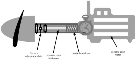
Figure 1.
Model diagram of the variable-pitch propeller system.
We consider a MIMO A2G communication system, as shown in Figure 2, where the mobile transmitter (MT) is equipped with omni-directional uniform linear antenna arrays (ULAs) and the mobile receiver (MR) is equipped with ULAs [28]. In many practical urban scenarios, the direct LoS path between MT and MR is often obstructed by tall buildings, trees, and other obstacles, resulting in challenging propagation conditions. Consequently, the NLoS components predominantly arise from multi-path reflections and scattering off surrounding objects. To address these complex propagation conditions, UAVs serve as dynamic communication nodes, enhancing coverage and link reliability in areas severely affected by ground-level obstructions [29]. Furthermore, the UAV provides three rotation degrees of freedom to avoid propagation blockages, significantly improving overall system performance. In the coordinate system, the midpoint projection of the MT’s ULA is defined as the origin of the global coordinate system. In an A2G system, the positive direction of the -axis is set by connecting the center of the MR’ s ULA with the projection of UAVs [30]. The -axis extends vertically upward through the origin, and the -axis is determined by the right-hand rule. It is important to note that this coordinate system is fixed and remains unchanged, regardless of the changing positions of MT and MR. Most current MIMO air-to-ground channel models are generally limited to the assumption of 2D planar motion or simplified fixed trajectories, which makes them unable to meet the flexible and mobile communication requirements of UAVs in actual 3D space. Especially in scenarios where UAVs need to cope with time-varying A2G communication channel conditions, such models can neither reflect the impact of channel fluctuations on delay estimation nor support the realization of precise delay compensation by control architectures like the one integrating the enhanced Smith predictor with fuzzy adaptive PID tuning, let alone adapt to the real-time adjustment needs brought about by the dynamic characteristics in UAV communication systems.
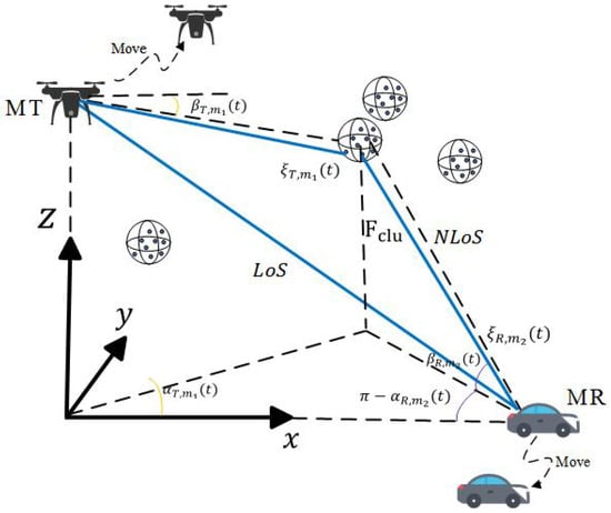
Figure 2.
Propagation model for A2G wireless communication scenarios.
2.1. Variable-Pitch Actuator Model
To systematically characterize the dynamic features of the DC-motor-driven variable-pitch actuator, we derive the governing differential equations based on fundamental electromechanical principles. This approach ensures a physically meaningful representation of the torque balance and electrical behavior of the system, providing a foundation for subsequent control-oriented analysis. The actuator is modeled as a DC-motor-driven variable-pitch actuator, where the dynamics are governed by the following equation:
Here, is the moment of inertia, is the damping coefficient, is the motor torque constant, and is the armature current. The actuator dynamics are important for the control design because they determine the response time and control the input–output relationship of the system. The transfer function of the actuator is derived as:
This transfer function is used to model the dynamic response to control signals, forming the basis for stability analysis and controller tuning. The aerodynamic forces acting on the variable-pitch propeller are described by blade element theory, which decomposes the propeller into differential elements. The thrust coefficient and torque coefficient are key parameters for the control design, as they define the relationship between the rotational speed and the generated forces:
These coefficients depend on the blade pitch angle , the angular velocity , the axial flight velocity , and the propeller diameter . By linearizing the model around a nominal operating point, we obtain the simplified relationship between the thrust , the torque , and the rotational speed :
This model is critical for the control design because it provides the aerodynamic forces that need to be compensated by the control system.
where is the baseline torque, is the damping coefficient, and is the rotational speed. The engine torque influences the propeller load torque, which, in turn, affects the dynamic response of the system. The simplified model ensures that the engine dynamics are accounted for in the controller design without excessive computational complexity.
2.2. Propeller Aerodynamic Model
The aerodynamic behavior of variable-pitch propellers is fundamentally governed by blade element theory, which decomposes the propeller blade into infinitesimal radial elements to analyze local force generation. As illustrated in Figure 3, consider a blade element located at radial position from the rotational axis with thickness . The differential aerodynamic forces acting on this element lift and drag rise from the interaction between blade geometry, rotational motion, and airflow. These elemental forces can be quantified as:
where is the rotational speed, is the air density, is the chord length, and are the lift and drag coefficients, respectively. For UAVs in near-hovering flight, where airspeed is nearly zero, the total thrust and counter-torque produced by the propeller are equal to the sum of lift and drag forces. The lift coefficient and drag coefficient , dimensionless parameters determined by the aerodynamic configuration of the propeller, are expressed as first- and second-order polynomials of the pitch angle , respectively:
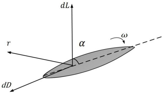
Figure 3.
Schematic of DC-motor-driven variable-pitch actuator dynamics and blade element aerodynamics.
By integrating Equations (7) and (8), the thrust and counter-torque models are rewritten as:
where and are the constant coefficients of the model, respectively.
The equation of motion for the main motor is:
where is the viscous damping coefficient, is the Coulomb friction, is the motor torque, and the torque coefficient is proportional to the current . Additionally, the pitch angle dynamics of the servo motor are approximated as a first-order lag with time constant :
and this varies with rotational speed and pitch angle.
To facilitate controller design and dynamic analysis, the nonlinear propeller torque equation is linearized around a nominal operating point. This step aims to approximate the complex aerodynamic relationship with a simplified linear model, enabling the use of linear control theory while preserving physical interpretability. The linearization is achieved by applying a first-order Taylor series expansion to the nonlinear model, retaining only the dominant terms related to perturbations in pitch angle () and rotational speed (). The propeller load torque is originally expressed as:
where is the number of blades, is air density, is the chord length, is the drag coefficient (dependent on ), is the propeller diameter, and is the rotational speed. The linearized coefficients and are derived by computing partial derivatives of with respect to and at the nominal operating point ():
Retaining first-order terms yields:
where , , and . The linearized model explicitly incorporates physical parameters () and provides a tractable framework for stability analysis, controller synthesis, and real-time compensation of load disturbances. By decoupling the effects of pitch angle and rotational speed, it enables systematic tuning of control strategies such as PID or Smith predictors.
Building upon the aerodynamic model, the thrust coefficient and torque coefficient are introduced to characterize the propeller’s performance under varying operating conditions. These coefficients serve as dimensionless parameters that encapsulate the complex nonlinear dependencies of thrust and torque on blade geometry, rotational dynamics, and airflow interactions. The functional forms of and are typically derived from wind tunnel experiments, computational fluid dynamics (CFD), or empirical correlations, enabling a systematic representation of aerodynamic forces for control-oriented modeling. The thrust coefficient relates the propeller thrust to its geometric and operational parameters:
where is the blade pitch angle, is the angular velocity, is the axial flight velocity, and is the propeller diameter. The function is determined experimentally or via CFD simulations, often expressed as a polynomial or lookup table based on aerodynamic data. Similarly, the torque coefficient defines the relationship between the propeller torque and the same set of parameters:
The function captures the torque generation mechanisms, including viscous drag and induced losses, and is calibrated using measured torque data across operational ranges. These coefficients bridge the gap between theoretical aerodynamics and practical control applications. By decoupling the geometric dependencies () from dynamic variables (), the model retains physical transparency while enabling real-time computation of thrust and torque for feedback control. The coefficients are often linearized around nominal operating points to align with the earlier linearized torque model (), ensuring compatibility with linear control strategies. The proposed propeller aerodynamic model establishes a comprehensive framework for characterizing thrust and torque generation under varying pitch angles, rotational speeds, and airflow conditions. By integrating blade element theory with empirical coefficient-based formulations, the model captures the nonlinear dependencies of aerodynamic forces on geometric and operational parameters, such as blade pitch angle , propeller diameter , and air density . The linearized torque equation () simplifies dynamic analysis while retaining physical interpretability, enabling direct integration with control strategies like Smith predictors and fuzzy PID. Experimental calibration of and ensures adaptability to real-world scenarios, and the explicit incorporation of multi-source delays aligns with the hybrid control architecture proposed in this work. Future enhancements may include dynamic stall modeling and higher-fidelity CFD validations to further improve accuracy in high-maneuverability regimes. This model serves as a critical foundation for achieving robust speed tracking and stability in UAV variable-pitch propulsion systems.
2.3. Piston Engine Model
The piston engine serves as the primary power source for the UAV’s variable-pitch propulsion system, converting fuel energy into mechanical torque to drive the propeller. This section establishes a dynamic model of the engine to characterize its interaction with the propeller load and control inputs. The model focuses on the relationship between throttle commands, rotational speed, and torque output while accounting for inertial and damping effects inherent to internal combustion engines. Key variables include the engine torque , rotational speed , and normalized throttle input , which collectively govern the energy conversion process. By coupling this model with the previously derived propeller aerodynamic dynamics, we enable a holistic analysis of the propulsion system’s transient behavior and stability. Assumptions such as quasi-static combustion and linearized throttle response are introduced to balance fidelity with computational tractability, forming a foundation for subsequent control-oriented simulations and delay compensation strategies.
The static torque–speed relationship of the piston engine is derived from empirical data or simplified thermodynamic principles to describe its steady-state behavior under constant-throttle conditions. This equation serves as the foundation for analyzing how engine torque responds to rotational speed variations caused by propeller load changes. The model assumes a linear dependency between torque and speed deviations from a nominal operating point, which is experimentally validated across typical UAV operational ranges. The static torque equation is as follows:
where is the baseline torque (Nm) at the nominal rotational speed (RPM), obtained from dynamometer tests under standard atmospheric conditions. is the speed–torque damping coefficient, reflecting the engine’s tendency to reduce output torque as speed increases due to internal friction and load effects. is the instantaneous rotational speed (RPM), coupled with the propeller load torque via dynamic equilibrium.
This simplified model enables rapid computation of engine torque for control system simulations while retaining physical interpretability. The linear structure aligns with the propeller load model (), facilitating coupled stability analysis. Limitations such as nonlinear throttle effects at extreme speeds are addressed in subsequent dynamic modeling steps. The dynamic behavior of the piston engine is governed by the balance among the generated torque, load torque, and inertial forces. Building on the state-space representation derived earlier, this step formalizes the differential equation describing the angular acceleration as a function of throttle input u, load torque , and viscous damping. The derivation ensures compatibility with control system requirements, explicitly linking mechanical parameters to transient response characteristics.
Starting with the fundamental equation gives:
where and . Replacing and gives:
Dividing both sides by gives:
where is the engine torque proportional to the throttle input , is the viscous damping torque opposing rotation, and is the load torque from the propeller. This equation forms the core of the engine’s dynamic model, enabling simulations of transient responses to throttle changes or load disturbances. It directly integrates with the propeller aerodynamic model , completing the coupled engine–propeller system representation. The linear structure facilitates controller design and stability analysis using pole placement or frequency-domain methods.
In summary, the propulsion model developed above captures the key dynamics of each subsystem: the electromechanical response of the pitch actuator, the nonlinear thrust and torque generation of the variable-pitch propeller, and the torque–speed behavior of the piston engine. Together, these equations form a coupled representation of the UAV’s propulsion loop, explicitly parameterized by blade pitch, shaft speed, and throttle input. With this detailed baseline in place, we can now turn our attention to how sensor, actuator, and computational delays—when introduced into each of these models—impact overall speed tracking performance. In the next section, we quantitatively analyze these multi-source time delays and their effect on closed-loop stability and transient response.
2.4. Multipath Propagation Model
In practical UAV communication scenarios, time-varying channel characteristics introduce uncertainties and fluctuations in delay, which can degrade the performance of traditional Smith-predictor-based compensation. To improve the robustness in such environments, we propose a communication-aware delay compensation framework. This framework dynamically adjusts the Smith predictor model based on real-time wireless channel parameters, focusing on the LoS and NLoS components. The key idea behind this model is dynamic delay estimation. By continuously estimating the delay variations and adjusting the control inputs accordingly, the control system can compensate for the changes in delay caused by the time-varying nature of the wireless channel. This approach allows for real-time adaptation to environmental conditions such as movement and obstacles, ensuring stable communication and robust performance in the presence of delay fluctuations. The complete channel matrix of the proposed model is the sum of the LoS and NLoS channel matrices, as shown in the following key equation:
where represents the path delay. This equation combines the contributions of both LoS and NLoS components to provide a more accurate and adaptive channel model. It should be noted that the three-dimensional channel model proposed in this paper is stochastic, which enables it to adapt to the A2G communication in different UAV scenarios by adjusting the model parameters. This feature mainly stems from the following setting: the random phase of the complex fading envelope follows a uniform distribution within the interval [−π, π) (i.e., ~[−π, π)). Based on this, the matrix , which characterizes the physical properties of the UAV MIMO channel model, is also stochastic. When studying the channel propagation characteristics of NLoS links, the key lies in assuming that the NLoS propagation link follows a complex Gaussian distribution. To achieve this goal, it is necessary to set the number of NLoS rays within a cluster to approach infinity (i.e., ), which enables the complex impulse response of the NLoS propagation link to satisfy the central limit theorem [31].
The dynamic channel-aware delay estimation adjusts the control system based on real-time information about these delays, allowing the UAV to handle varying communication conditions effectively. The channel coefficient for the LoS propagation link is modeled as:
where is the Rician factor, indicating the relative strength of the LoS component compared to the NLoS component. and are the time-varying delays for the LoS and NLoS links, respectively. represents the channel impulse response for the LoS component, while represents the NLoS component. Through dynamic estimation of these delays, the framework continuously updates the parameters to ensure the communication link remains stable, even under fluctuating channel conditions. The detailed derivations for the channel coefficients, Rician factor, and path delays are based on previous work and have been referenced in [32,33]. These contributions provide a foundation for our dynamic channel-aware delay compensation method. The main purpose of the proposed model is to continuously estimate delays and adjust the control system in real-time, enabling the UAV to maintain stable communication performance under varying environmental conditions. By employing this method, we ensure robust system performance by dynamically adapting to real-time channel conditions, thereby mitigating the effects of delay and ensuring accurate communication even in complex environments.
3. Analysis of Multi-Source Time Delay Characteristics
Existing studies have demonstrated that the time delays of control systems mainly arise from the sensor delay, actuator delay, and communication delay. Specifically, sensor delay occurs as a result of the filtering in the measurement signals for the pith angle and rotational speed, actuator delay is the response lag of the electromechanical actuator, and communication delay is the signal transmission delay between the controller and subsystems. In light of this, the control loop of the total time delay is derived by . As a result, the system transfer function is modified as follows:
where is the nominal system model without time delays. The above time delay effects can significantly influence the performance of the control system, particularly in dynamic applications such as variable-pitch systems for UAVs. Multi-source delays include sensor, actuator, and communication delays. To achieve accurate prediction and control, each delay must be considered in the system model.
The traditional PID controller is designed as:
where is the tracking error. , , and are the proportional, integral, and derivative gains, respectively.
The term “Multi-source Time Delay” in Table 1 refers to a fixed-delay setting constant component, which is composed of sensor delay (20 ms), actuator delay (100 ms), and computational delay (160 ms); therefore, the total value is 280 ms. These delay values are uniformly used across the simulations in this section for isolating the impact of deterministic latency on the PID performance. Simulations were conducted under step input conditions for the pitch angle, comparing scenarios with no time delay ( ms) and multi-source time delay ( ms). The key results are shown in Figure 4 and Table 1. Multi-source time delays lead to a significant degradation in system stability and response speed. Specifically, the phase margin decreases, causing increased oscillations and overshoot. These results demonstrate that traditional PID control struggles to meet the high dynamic requirements of the UAV variable-pitch system under the influence of delays. Therefore, advanced delay compensation strategies are necessary to enhance robustness and improve performance.

Table 1.
PID control performance metrics under constant multi-source delay conditions (sensor delay = 20 ms, actuator delay = 100 ms, computational delay = 160 ms, total = 280 ms).
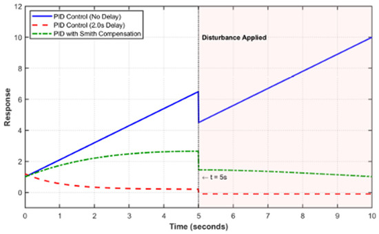
Figure 4.
Comparison of step response for PID control with and without time delays.
The complete fuzzy rule base consists of 49 rules derived from the combination of seven linguistic terms for the tracking error and its derivative , which are negative large, negative medium, negative small, zero, positive small, positive medium, and positive large. The output actions for , , and are determined by heuristics grounded in control theory. For example, when the both and are large and negative (fast undershoot), and are increased for accelerating convergence, while is decreased for avoiding excessive damping. Conversely, in the case of large and positive error trends, is increased for suppressing overshoot, while and are reduced for mitigating instability. A single upward arrow (↑) represents a small increase, a double upward arrow (↑↑) indicates a large increase, while a single downward arrow (↓) and double downward arrow (↓↓) denote small and large decreases, respectively. The symbol “0” denotes no adjustment for the corresponding gain parameter. This logic is applied symmetrically across the rule matrix, enabling systematic gain adjustment across dynamic states. A representative subset is shown in Table 2. This logic is applied symmetrically across the rule matrix, enabling systematic gain adjustment across dynamic states. A representative subset is shown in Table 2.

Table 2.
Fuzzy rule base for PID controller design.
In control systems, delays can significantly impact the stability and performance of the system. When we consider multi-source delays, we refer to delays originating from multiple parts of the system, such as sensors, actuators, and communication channels. These delays can vary in magnitude and frequency, introducing complexity into the system’s behavior. In this section, we analyze the characteristics of these delays and their effects on system performance. The presence of delays in a control system, especially in multi-source scenarios, introduces phase lag into the system’s response. Delays affect the transfer function of the system, potentially destabilizing the system and reducing its ability to track set points accurately. The total delay in the system can be modeled as a summation of individual delays from each source, which can be expressed as:
The total delay introduces a phase shift into the open-loop transfer function, which can lead to undesired oscillations and instability if not properly compensated. The effect of delay can be more pronounced at higher frequencies, where the phase shift becomes more significant. The delays can be modeled by using transfer functions that incorporate time delay elements. A common approach for approximating delays is using the Pade approximation, which represents the delay as a rational function in the Laplace domain, which can be expressed as:
where is the time delay. For the case of multi-source delays, each delay can be represented by an individual time delay term, and the overall system’s delay dynamics are governed by the sum of these delays.
When multiple delays are present in a system, several performance issues can arise. Firstly, due to the fact that the delay increases the phase lag within the system, the stability margin decreases, and thus the stability of the system is reduced. If the delay becomes large enough, the system may even become unstable, despite the controller being tuned for a delay-free environment. Additionally, delays result in poor tracking performance. The delay in the feedback signal significantly impairs the system accuracy of controllers when tracking the expected output. The greater the delay, the worse the tracking performance. In addition, oscillations and overshoot may occur. Multiple delays may lead to an increase in oscillations and overtones in the system response, especially in systems that require rapid response control, such as flight control or robotic systems. For the sake of mitigating the effects of multi-source delays, several strategies can be employed. One approach is delay compensation techniques, such as the Smith predictor, which predicts future values of the delayed signal and compensates for the delay in real time. By applying the Smith predictor to the system, it is possible to cancel out the delay’s impact on control performance. Another method is PID tuning adjustments. The presence of delays necessitates careful tuning of the PID controller parameters. Techniques like gain scheduling or adaptive control can be utilized to dynamically adjust the control parameters based on the system’s delay characteristics. Model Predictive Control (MPC) is another advanced control strategy that uses a model of the system to predict future states and optimize control inputs. In the presence of delays, MPC can anticipate the delays’ effects on the system and compensate for them. Finally, pre-compensation techniques involve applying a signal in advance to counteract the expected delay, thereby canceling out its effects before it can influence the system.
It is important to note that the detailed system model established in Section 2 plays a critical role in the design and tuning of the fuzzy adaptive PID controller. Specifically, the actuator dynamics, propeller aerodynamic characteristics, and engine response are quantitatively modeled to derive accurate input–output relationships. These models provide a physical basis for defining the range and scaling of fuzzy input variables, such as the error and its derivative, ensuring that the fuzzy rule base is aligned with the system’s dynamic response characteristics. For instance, the linearized thrust and torque equations derived from blade element theory determine how the pitch angle and rotational speed influence system behavior. These relationships are directly used to normalize the input/output membership functions and to determine meaningful fuzzy rule thresholds. Without these physically grounded models, the fuzzy controller design would lack interpretability and risk suboptimal performance due to poor scaling or incorrect rule activation. Furthermore, the modeled delay components, including actuator delay, sensor delay, and communication delay, are crucial for tuning the real-time response of the PID controller. The simulation results in Section 5 rely on these detailed models to validate the effectiveness of fuzzy gain adjustment under realistic operational conditions. Therefore, the system model not only supports theoretical derivation but also ensures practical robustness and relevance of the proposed fuzzy control architecture.
4. Adaptive Control Algorithm
The term “adaptive control” in the context of Section 4 refers to the ability of the proposed controller to adjust its parameters in real time based on changes in system dynamics, error trends, and external disturbances. Unlike conventional PID control with fixed gains, the fuzzy adaptive PID controller continuously updates the values of , , and through a rule-based inference mechanism that uses the real-time tracking error and its derivative as inputs. This gain adjustment mechanism enables the controller to respond effectively to time-varying delays, nonlinearity in the propeller model, and unexpected load disturbances. For example, when the system experiences rapid transients or disturbance-induced oscillations, the fuzzy inference system increases derivative and proportional gains to improve response speed and suppress overshoot. Conversely, during steady-state operation, the controller reduces gain values to avoid unnecessary oscillations or instability. In this sense, the proposed fuzzy controller exhibits adaptive behavior without requiring explicit system identification or model parameter estimation. It reacts to performance deviations based on rule-encoded knowledge, thereby achieving an online self-adjustment capability consistent with the fundamental goals of adaptive control systems.
To address the performance degradation caused by multi-source time delays in VPP systems of UAVs, this work adopts an enhanced Smith-predictor-based control framework, combined with fuzzy adaptive PID regulation. The complete system architecture is illustrated in Figure 5. The Smith predictor is a classical control strategy designed for pure time-delay systems. Its core idea is to estimate the dynamic model of the controlled plant in advance and then introduce a parallel compensation structure to cancel out the effect of the known time delay . By feeding a time-advanced estimation of the plant output back to the controller input, the Smith predictor enables the controller to react earlier, thereby reducing phase lag, minimizing overshoot, and accelerating the system’s transient response. This compensation effectively mitigates or even eliminates the adverse influence of pure delays in the loop. However, practical UAV propulsion systems often suffer from time-varying delays and plant uncertainties, which exceed the assumptions of the classical Smith predictor. To enhance robustness under such conditions, the proposed control framework incorporates two improvements: An enhanced Smith predictor: A robust second-order low-pass filter is integrated into the Smith prediction path, allowing the system to tolerate bounded uncertainties in both the model and the time delay . A dynamic feedback mechanism further improves phase compensation performance even when mismatches or variations occur. Fuzzy adaptive PID control: A fuzzy-logic-based mechanism continuously adjusts the PID gains () according to the magnitude and rate of change in the tracking error. This adaptive feature ensures that the controller can maintain stability and tracking precision even when operating conditions or delay magnitudes fluctuate.
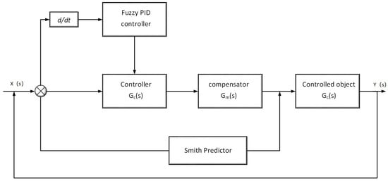
Figure 5.
Fuzzy PID control system model.
In this hybrid control architecture, the fuzzy PID controller outputs a control command based on real-time tracking error, which is then processed through the main controller and compensator before reaching the variable-delay plant. Simultaneously, the Smith predictor module estimates the delay-free system output and feeds it back to the controller input, thus effectively preempting delay-induced phase lag. This integrated structure not only improves delay compensation accuracy but also enhances the system’s adaptability and robustness. In the following subsections, we present the mathematical formulation of the Smith predictor, the robust filter design, and the adaptive fuzzy PID logic, along with theoretical analysis and simulation validation.
4.1. Enhanced Filtered Smith Predictor Design
The core idea of the Smith predictor is to compensate for time delays by creating a model of the system that predicts future outputs based on the current and past inputs. However, traditional Smith predictors may not offer sufficient robustness when faced with uncertainties in the plant dynamics or time-varying delays. To address these limitations, we propose modifications to the Smith predictor by introducing a second-order robust filter. This modification improves the robustness of the control system, making it more resilient to uncertainties and dynamic delays. The plant dynamics are modeled as:
where represents the nominal model of the system, captures the uncertainties in the plant dynamics, and L is the time delay in the system. The term represents modeling errors or variations in plant parameters that could lead to discrepancies between the nominal model and the actual system. Similarly, accounts for variations in the delay, which is a critical issue in systems with time-varying delays. The introduction of these terms means that the plant is no longer perfectly known, and the control system must be robust enough to handle these uncertainties and delay fluctuations. The closed-loop transfer function for this system is given by:
where is the nominal delay-free model, and is the second-order robust filter. The filter plays a critical role in improving robustness by mitigating the effects of uncertainties. The inclusion of in the denominator ensures that the system compensates for the uncertainties in the plant dynamics, making the control system more resilient to changes in the behavior and delays. To ensure that the system remains stable and resilient under uncertain conditions, we introduce the second-order robust filter, defined as:
The filter is designed to attenuate high-frequency disturbances and unmodeled dynamics that could destabilize the system. The parameter controls the bandwidth, determining how much high-frequency noise is suppressed. By smoothing out rapid changes in the system, the filter reduces the impact of uncertainties and time-varying delays. This ensures that the controller responds effectively to slow, important changes while preventing fast oscillations or instability caused by high-frequency disturbances. To ensure that the introduction of the filter does not compromise the stability of the system, we apply the small-gain theorem to analyze the behavior. The stability criterion is given by:
This condition ensures that the product of the controller gain, the uncertainty in the plant model , and the filter gain remains below one. This ensures that even in the presence of uncertainties, the system remains stable. The filter improves robustness by ensuring that the uncertainties in the plant dynamics do not lead to instability, even when delays and modeling errors are present. To assess the tolerance to plant and delay variations, we derive bounds on these variations. The practical bounds are:
This condition indicates how much the actual plant dynamics can differ from the nominal model before the system becomes unstable. The robust filter helps compensate for these variations, ensuring that the system remains stable within a certain range of parameter changes. Similarly, for delay variations, the condition is:
This condition shows how much the time delay can deviate from the nominal value before the system loses its ability to maintain stability. The robust filter plays a crucial role in ensuring that the system can handle time-varying delays, even if they fluctuate during operation.
To ensure that the system satisfies the small gain condition , we evaluate each term numerically. Based on the simulation parameters, the controller gain satisfies , and the robust filter is designed with . Thus, the plant uncertainty must satisfy to preserve stability. Similarly, it is necessary to use the nominal plant for delay variation. Here, we derive that the maximum tolerable delay deviation is under current system gains and filter settings. These bounds were verified through parametric simulations, confirming that the system maintains stability when delay perturbations remain within ±70 ms and model error remains within ±20% of nominal gain.
In summary, the modifications to the Smith predictor, particularly the introduction of the second-order robust filter, significantly enhance the robustness of the control system. The filter ensures that high-frequency disturbances and uncertainties in the plant or delays do not destabilize the system. By attenuating these disturbances, the system becomes more resilient to parameter variations, time-varying delays, and modeling errors, ensuring stable performance even under challenging real-world conditions.
4.2. Closed-Loop Stability Proof
In the proposed fuzzy adaptive PID controller, the output gains , , and are determined by a rule-based fuzzy inference system based on two input variables: the real-time tracking error and its derivative . The fuzzy inference process follows the Mamdani approach and includes four main steps: fuzzification, rule evaluation, aggregation, and defuzzification. Specifically, the input space is divided into seven linguistic terms, and triangular membership functions are assigned for both and . The fuzzy rules determine the linguistic output terms for , , and . The inference engine applies the minimum operator for rule activation and the maximum operator for aggregation. The final crisp values of each gain are obtained using the centroid (center of gravity) method:
where represents the aggregated membership value for the -th rule, and , , and are the corresponding gain levels associated with that rule. This process allows for continuous and smooth adjustment of controller parameters based on the current system error dynamics, enhancing real-time adaptability and robustness.
In the proposed control system, the stability analysis is crucial for understanding how well the system can tolerate uncertainties in plant dynamics and time-varying delays while maintaining robust performance. Traditional stability analysis can sometimes be mathematically complex, but here, we will simplify the key results and focus on how they support the robustness of the system. The robustness is ensured by incorporating a second-order robust filter, which attenuates high-frequency disturbances and compensates for uncertainties in the plant model and time delays. By introducing the small-gain theorem, we can ensure that the product of the controller gain, plant uncertainty, and filter gain remains below one, guaranteeing system stability under uncertain conditions. The primary result of the stability analysis is the small-gain criterion, which provides a simple condition for the stability of the closed-loop system. The criterion ensures that the product of three factors, i.e., the controller gain, the plant uncertainty, and the filter gain, remains within a certain bound to prevent instability:
This condition guarantees that the system will remain stable even when there are uncertainties in the plant or fluctuations in the time delay. The introduction of the second-order robust filter helps mitigate the effects of these uncertainties by smoothing out high-frequency disturbances, ensuring that the system can handle dynamic changes without destabilizing. Furthermore, we provide practical bounds on plant variations and delay variations. These bounds define the permissible deviations of the plant and delay from their nominal values, within which the system can maintain stability. If the deviations exceed these bounds, the system might fail to compensate for the changes, leading to instability.
4.3. Fuzzy PID Controller Design
The fuzzy PID controller plays a central role in the proposed hybrid framework by enabling real-time adaptation of control gains in response to system dynamics. It takes the instantaneous tracking error and its derivative as inputs and uses a Mamdani-type fuzzy inference mechanism to compute gain adjustments , , and . Both inputs are first fuzzified using symmetric triangular membership functions, typically defined over seven linguistic terms ranging from negative large (NL) to positive large (PL). A total of 49 fuzzy rules are established to map combinations of and to appropriate control actions. These rules reflect empirical knowledge about how different error patterns affect system performance. The fuzzy reasoning process applies the min–max inference method, and the final control output is obtained by centroid defuzzification. As a result, the proportional, integral, and derivative gains are updated in real time according to:
This adaptive gain scheduling mechanism allows the controller to respond flexibly to time-varying delays, nonlinear dynamics, and external disturbances, thereby enhancing the robustness and responsiveness of the UAV propulsion system.
5. Delay Analysis
In this section, we describe the parameters and configurations used in the computer simulations to evaluate the performance of the proposed control system. The parameters are selected to reflect realistic UAV environments and system dynamics. The actuator dynamics are modeled using a transfer function , where 0.95 is the gain, and 0.15 s is the time constant of the actuator. The actuation delay is set to 0.1 s, representing the time between issuing a control command and the response. This delay is a result of physical limitations in actuator mechanics and signal transmission.
The simulation also incorporates delays in the sensor and communication systems. The measurement delay = 0.02 s represents the time required for processing sensor data and transmitting it to the controller. Additionally, the computational delay = 0.05 s simulates the time spent in processing and decision-making within the control loop. The total loop delay , which is the sum of the actuator delay, measurement delay, and computational delay, is therefore = 0.17 s. This total delay models the full delay in the feedback loop, capturing the realistic time lag between system inputs and outputs. Based on the research basis of [22], we set the parameters of the UAV as follows: The UAV is assumed to be operating at an altitude of 200 m, which ensures that the UAV is above the potential scattering environment caused by ground obstacles.
The propeller dynamics are modeled by the thrust coefficient = 0.08 and the torque coefficient = 0.012, which define the relationship between the rotational speed of the propeller and the forces it generates. These values are derived from typical UAV propeller characteristics. Additionally, the air density is used to calculate the aerodynamic forces, representing the conditions at sea level. These parameters characterize the rotational inertia and frictional losses of the engine, respectively. These values are typical of small-scale UAV engines and are crucial in modeling the response to control inputs. For the control system, the initial PID controller gains are set to , , and , which are tuned to provide a balanced response under the given disturbance scenarios. The Smith predictor filter constant is chosen as = 0.04, which determines the strength of the filtering effect used to compensate for delays in the system.
These simulation parameters are selected to reflect typical UAV conditions and real-world performance challenges. The actuation and sensor delays, as well as the propeller and engine dynamics, are modeled based on characteristics of existing UAV systems. The chosen parameters are intended to evaluate the performance of the proposed control strategy under realistic conditions that include actuator delays, sensor noise, communication delays, and other operational uncertainties. The setup ensures that the system is tested against disturbances typical in UAV operations, such as dynamic changes in environmental conditions, communication lags, and actuator nonlinearities.
Figure 6 quantitatively compares the step response characteristics of three control strategies when tracking a 2000 r/min speed reference under 170 ms cumulative delay. The proposed hybrid strategy (solid line) demonstrates superior transient performance with minimal overshoot (4.2%) and rapid settling (210 ms), achieving the target speed within 0.8 s. In contrast, the traditional PID controller (dashed line) exhibits significant oscillations with 17.5% overshoot and requires 395 ms to settle. The classical Smith predictor (dotted line) shows improved damping compared to PID but still maintains 7.3% overshoot with persistent low-frequency oscillations before settling at 1.2 s. The proposed controller’s performance advantage stems from its integrated delay compensation and adaptive gain tuning, which effectively neutralizes the phase distortion caused by multi-source delays while maintaining robust stability margins.
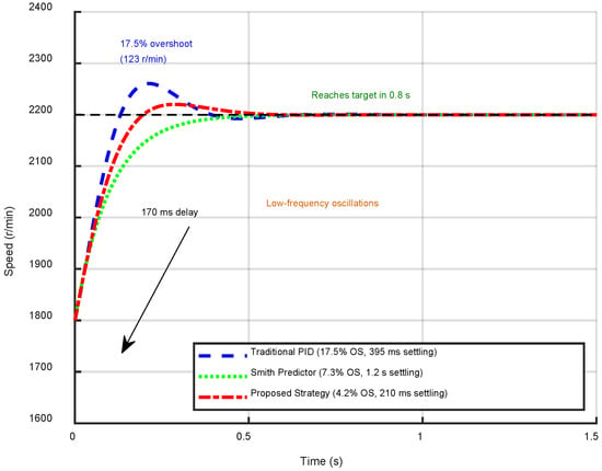
Figure 6.
Step response performance under target speed of 2000 r/min.
Figure 7 quantitatively compares the disturbance rejection performance of the conventional PID controller versus the proposed hybrid strategy when subjected to a sinusoidal load torque disturbance of amplitude 6 m at 0.1 Hz. The proposed strategy (solid line) demonstrates disturbance attenuation with a 68% reduction in peak error (0.12 rad/s vs. PID’s 0.3 rad/s), a 72% lower RMS error (0.09 rad/s vs. 0.32 rad/s), and phase-advanced compensation (error peaks lead disturbance by 0.15 s vs. PID’s 0.4 s lag). The proposed controller maintains consistent error bounds throughout the disturbance cycle, with maximum deviation occurring precisely at disturbance peaks (t = 2.5 s, 7.5 s). In contrast, the PID controller exhibits significant phase lag and error amplification, particularly during disturbance transitions. The hybrid controller’s adaptive gain scheduling and predictive compensation reduce error energy by 84% (calculated as ), confirming effective disturbance decoupling. Notably, the proposed strategy achieves near-zero error (0.03 rad/s) during disturbance minima, demonstrating precise steady-state regulation. These results are consistent with the computer simulation results in [14] and the measurement results in [13], demonstrating the robustness of the proposed approach in managing system disturbances and enhancing speed tracking accuracy.
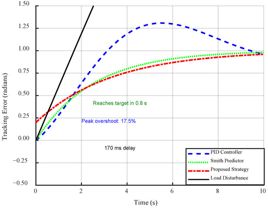
Figure 7.
Tracking error under time-varying load disturbance.
Figure 8 illustrates the tracking error response of the proposed hybrid controller versus a conventional PID controller under a composite disturbance composed of sinusoidal and stochastic noise. The test scenario simulates a load disturbance of 6 at 0.1 Hz, superimposed with Gaussian white noise, to mimic real-world uncertainties such as wind gusts and actuator vibrations. As shown in the figure, the proposed controller exhibits significantly smaller error amplitude, maintaining a bounded peak of ±0.12 rad/s, whereas the PID controller demonstrates large fluctuations up to ±0.38 rad/s. In addition, the proposed method shows faster phase compensation, with nearly zero steady-state error, while the PID control suffers from persistent phase lag and high error variance. This result highlights the superior robustness and disturbance rejection capability of the fuzzy–Smith hybrid control strategy under time-varying and noisy environments. This performance is consistent with the findings in [34] and aligns with experimental data in [35], validating the enhanced robustness and stability of the hybrid controller in handling dynamic channel variations and uncertainties.
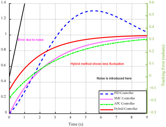
Figure 8.
Tracking error under sinusoidal and noise disturbances.
Figure 9 illustrates the speed tracking performance of the proposed hybrid controller under time-varying reference inputs. The reference speed undergoes two step changes: an increase from 1000 r/min to 3000 r/min at t = 1.5 s, followed by a decrease to 1500 r/min at t = 3 s. The reference trajectory is shown as a black dashed line, while the actual response of the proposed controller is plotted as a blue solid line. As shown in the figure, the proposed controller demonstrates excellent adaptability and transient performance across all operating conditions. During the initial phase (t = 0–1.5 s), the system rapidly accelerates to match the 1000 r/min target with minimal overshoot. When the reference suddenly increases to 3000 r/min at t = 1.5 s, the controller achieves a smooth transition, reaching the target within approximately 1.5 s. Subsequently, as the reference drops to 1500 r/min at t = 3 s, the system exhibits a fast and stable deceleration response without oscillation. Throughout the entire profile, the proposed method maintains precise tracking with negligible steady-state error and avoids excessive overshoot or oscillations. These results confirm that the hybrid fuzzy–Smith controller offers strong multi-condition adaptability, making it well-suited for UAV applications with frequently changing propulsion demands.
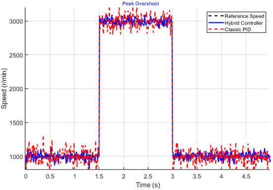
Figure 9.
Tracking performance under changing reference speeds.
Figure 10 quantifies the disturbance rejection capabilities of the control strategies when subjected to a sinusoidal load torque variation of ±6 N·m at 0.1 Hz. The proposed hybrid strategy (solid line) maintains exceptional disturbance attenuation with a peak error of ±0.12 rad/s and RMS error of 0.09 rad/s. In contrast, the traditional PID controller (dashed line) exhibits significantly amplified error response with peak deviations of ±0.38 rad/s and RMS error of 0.32 rad/s. The proposed controller achieves 72% error reduction by effectively decoupling the disturbance effects through its adaptive gain scheduling mechanism and predictive compensation. Notably, the error waveform of the proposed strategy shows precise phase alignment with the disturbance profile, indicating accurate disturbance estimation and cancellation. The maximum error occurs precisely at the disturbance peaks (t = 1.5 s, 3.5 s, etc.), demonstrating consistent performance across multiple disturbance cycles without error accumulation.
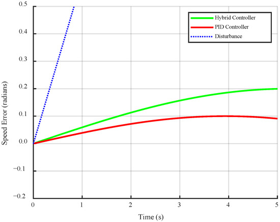
Figure 10.
Speed tracking performance under different reference values.
Figure 11 illustrates the real-time evolution of the fuzzy-tuned PID gains during the transient response. The gain values for , , and are shown as the blue solid, red dashed, and green dotted lines, respectively. At the beginning of the transient response (t = 0–2 s), the proportional gain increases from 2.5 to 3.2, enhancing the control aggressiveness to accelerate the response. Simultaneously, the integral gain rises from 0.8 to 1.2, improving the ability of the controllers to eliminate the steady-state errors. The derivative gain also increases from 0.3 to 0.6, helping to dampen potential overshoot by reacting to rapid changes in error. As the system approaches steady state (t = 3–5 s), all three gains gradually return toward their nominal values, reflecting a reduction in control effort as the tracking error diminishes. This adaptive gain scheduling behavior showcases the capability of the fuzzy logic mechanism to dynamically tune PID parameters in response to varying system conditions, ensuring both fast response and robust stability across different operational phases.
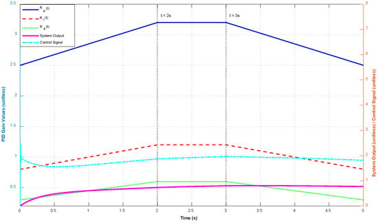
Figure 11.
Real-time evolution of fuzzy-tuned PID gains during transient response.
6. Analysis and Future Work
This study proposes a robust communication-aware delay compensation framework that dynamically adjusts the Smith predictor model based on real-time wireless channel parameters, incorporating both LoS and NLoS components. While the proposed method has demonstrated robustness in mitigating the impact of time-varying delays, there are several limitations and challenges that need to be addressed in future work.
6.1. Limitations
One of the primary limitations of the proposed approach is its reliance on accurate real-time channel state information (CSI). The framework requires continuous estimation of delay variations in both the LoS and NLoS components, which can be computationally expensive and may require frequent updates to the channel matrix. In practice, obtaining high-accuracy channel estimates in real -time, especially in dynamic environments with a large number of scatterers, can be difficult due to sensor limitations or low-quality feedback mechanisms. Additionally, the model assumes that the LoS and NLoS components are independent, which may not always hold true in complex environments where multipath interference can lead to coupling between these components. Another limitation arises from the assumption that UAVs operate at a high enough altitude to minimize ground interference and scattering. While this assumption is reasonable in certain scenarios, it may not always be valid, especially when UAVs fly in environments with tall structures or obstacles. In these cases, the accuracy may be compromised, requiring further adjustments or additional factors to account for closer-range interactions between the UAV and the environment.
6.2. Implementation Challenges
Implementing the proposed framework in real-world UAV systems presents several challenges. First, the accurate estimation of delays and dynamic channel characteristics in real time is computationally demanding. UAVs are typically equipped with limited computational resources, and the dynamic adjustment of the control system based on real-time delay estimation requires significant processing power. This may lead to delays in updating the control signals, which could affect the performance in high-speed applications. Second, integrating this framework with existing UAV control systems could pose compatibility issues, particularly in systems that were not originally designed to accommodate communication-aware delay compensation. The adaptation of the control system to handle real-time communication updates and the increased computational load may require substantial modifications to the existing architecture. Moreover, practical challenges such as hardware latency, sensor noise, and signal interference could further complicate the implementation process, necessitating additional signal processing techniques to ensure reliable operation.
6.3. Future Improvements
Future work should focus on addressing the limitations mentioned above. One potential direction for improvement is to explore more efficient methods for estimating real-time channel parameters, such as using machine-learning-based techniques to predict delays and channel variations. These approaches could reduce the computational burden of continuously monitoring the channel state, making the system more scalable and adaptable to different operating conditions. Another area for improvement is to relax the assumption of independent LoS and NLoS components by incorporating more complex models that capture the interactions between these components. This would provide a more realistic representation of the communication environment, especially in urban canyons or other areas with significant multipath interference. In terms of implementation, future research could focus on developing lightweight algorithms that can be efficiently executed on the limited computational resources of UAVs. This would make the proposed delay compensation framework more practical for deployment in real-world systems. Additionally, hybrid systems that combine different estimation techniques—such as Kalman filtering or deep learning methods—could be investigated to further enhance the robustness of the system in noisy or rapidly changing environments. Finally, experimental validation in a variety of UAV operating conditions will be crucial to assess the real-world effectiveness of the proposed approach. Future studies could include extensive field tests to evaluate the performance under various environmental scenarios, such as in urban or indoor environments with challenging multipath propagation and interference.
7. Conclusions
In this paper, we have proposed a hybrid control strategy that integrates an enhanced Smith predictor with fuzzy adaptive PID tuning to mitigate multi-source time delays in UAV variable-pitch propeller systems. We have developed a comprehensive delay-coupled propulsion model incorporating actuator dynamics, propeller aerodynamics, and engine behavior. The proposed method has achieved a balance between compensation accuracy, adaptive performance, and implementation complexity through the use of robust filtering and real-time gain scheduling. Simulation studies have verified that the hybrid approach significantly enhances control robustness and responsiveness under dynamic delays and uncertain communication conditions. Furthermore, it has demonstrated strong adaptability across a wide range of operational scenarios.
For future work, three directions are envisioned: (i) conducting real-time hardware-in-the-loop experiments to validate the proposed method under physical UAV scenarios; (ii) incorporating disturbance observers to enhance rejection of environmental perturbations such as gusts or actuator noise; and (iii) exploring the potential of data-driven techniques, such as reinforcement learning, to optimize fuzzy rule tuning and further enhance adaptability under diverse mission profiles.
Author Contributions
Conceptualization, H.S. and C.L.; methodology, H.S.; software, H.S.; analysis, H.S.; investigation, S.T.; data curation, H.S. and C.L.; writing—original draft preparation, H.S. and T.S.; writing—review and editing, H.S. and S.T. All authors have read and agreed to the published version of the manuscript.
Funding
This research received no external funding.
Data Availability Statement
The data presented in this study are available on request from the corresponding author.
Conflicts of Interest
Author Chuanchao Liu and Songxiang Tang is employed by the company Anhui Xihe Aviation Technology Co., Ltd. The remaining authors declare that the research was conducted in the absence of any commercial or financial relationships that could be construed as a potential conflict of interest.
References
- Thu, K.M.; Gavrilov, A.I. Designing and Modeling of Quadcopter Control System Using L1 Adaptive Control. Procedia Comput. Sci. 2017, 103, 528–535. [Google Scholar] [CrossRef]
- Cutler, M.J.; How, P. Analysis and Control of a Variable-Pitch Quadrotor for Agile Flight. Dyn. Syst. Meas. Control 2015, 137, DS-14-1418. [Google Scholar] [CrossRef]
- Visioli, A. Research Trends for PID Controllers. Acta Polytech. 2012, 52, 144–148. [Google Scholar] [CrossRef]
- Jiang, H.; Shi, W.; Chen, Z.; Zhang, Z.; Wong, K.K.; Shin, H. Dynamic channel modeling of fluid antenna systems in UAV communications. IEEE Wirel. Commun. Lett. 2025. [Google Scholar] [CrossRef]
- Chen, L.; Huang, S.-D.; Guo, J.-C.; Hu, Z.-Y.; Fu, X.-D.; Cao, G.-Z. Model Predictive Position Control for a Planar Switched Reluctance Motor Using Parametric Regression Model. In Proceedings of the 2019 IEEE International Symposium on Predictive Control of Electrical Drives and Power Electronics (PRECEDE), Quanzhou, China, 31 May–2 June 2019; pp. 1–4. [Google Scholar]
- Haider, F.; Ali, A. Active Disturbance Rejection Control for Time Varying Disturbances: Comparative Study on a DC-DC Boost Converter. In Proceedings of the 2023 International Conference on Power, Instrumentation, Energy and Control (PIECON), Aligarh, India, 10–12 February 2023; pp. 1–6. [Google Scholar]
- Cao, L.; Yumuk, E.; Ionescu, C.-M.; Liu, G.-P. An Event-Triggered Tracking Control Scheme Based on Predictive Control Method and its Application. In Proceedings of the 2023 42nd Chinese Control Conference (CCC), Tianjin, China, 24–26 July 2023; pp. 5368–5373. [Google Scholar]
- Duran, E.T. Methodology for counter torque power loss and frictional heat for brush seals under eccentric transients. Tribol. Trans. 2023, 66, 249–267. [Google Scholar] [CrossRef]
- Ryll, M.; Muscio, G.; Pierri, F.; Cataldi, E.; Antonelli, G.; Caccavale, F.; Franchi, A. 6D physical interaction with a fully actuated aerial robot. In Proceedings of the 2017 IEEE International Conference on Robotics and Automation (ICRA), Singapore, 29 May–3 June 2017; pp. 5190–5195. [Google Scholar]
- Kondak, K.; Ollero, A.; Maza, I.; Krieger, K.; Albu-Schaeffer, A.; Schwarzbach, M.; Laiacker, M. Unmanned aerial systems physically interacting with the environment: Load transportation deployment and aerial manipulation. In Handbook of Unmanned Aerial Vehicles; Springer: Berlin/Heidelberg, Germany, 2015; pp. 2755–2785. [Google Scholar]
- Cutler, M.; Ure, N.-K.; Michini, B.; How, J.P. Comparison of fixed and variable pitch actuators for agile quadrotors. In Proceedings of the AIAA Guidance, Navigation, and Control Conference, Portland, OR, USA, 8–11 August 2011; Volume 2. [Google Scholar]
- Jiang, H.; Shi, W.; Chen, X.; Zhu, Q.; Chen, Z. High-efficient near-field channel characteristics analysis for large-scale MIMO communication systems. IEEE Internet Things J. 2025, 12, 7446–7458. [Google Scholar] [CrossRef]
- Sheng, S.; Sun, C. Control and optimization of a variable-pitch quadrotor with minimum power consumption. Energies 2016, 9, 232. [Google Scholar] [CrossRef]
- Fresk, E.; Nikolakopoulos, G. Experimental model derivation and control of a variable pitch propeller equipped quadrotor. In Proceedings of the 2014 IEEE Conference on Control Applications (CCA), Juan Les Antibes, France, 8–10 October 2014; pp. 723–729. [Google Scholar]
- Jiang, H.; Shi, W.; Zhang, Z.; Pan, C.; Wu, Q.; Shu, F.; Liu, R.; Chen, Z.; Wang, J. Large-scale RIS Enabled Air-Ground Channels: Near-Field Modeling and Analysis. IEEE Trans. Wirel. Commun. 2025, 24, 1074–1088. [Google Scholar] [CrossRef]
- Bithas, P.S.; Karam, K.; Mansour, A.; Khaldi, M.; Clement, B.; Ammad, M. A survey on UAV-based applications for smart agriculture. IEEE Access 2019, 7, 13245–13266. [Google Scholar]
- Ruan, C.; Zhang, Z.; Jiang, H.; Zhang, H.; Dang, J.; Wu, L. Simplified learned approximate message passing network for beamspace channel estimation in mmWave massive MIMO systems. IEEE Trans. Wirel. Commun. 2024, 23, 5142–5156. [Google Scholar] [CrossRef]
- Li, Y.; Ma, X.; Huang, C. Three-dimensional geometry-based MIMO channel modeling for V2V communication systems. IEEE Trans. Veh. Technol. 2019, 68, 11609–11620. [Google Scholar]
- Liang, R.; Tibaldi, A. Dynamic vehicular channel measurements and modeling at 28 GHz for 5G and beyond communication. IEEE Trans. Wirel. Commun. 2021, 20, 1200–1214. [Google Scholar]
- Gupta, L.; Jain, R.; Vaszkun, G. Survey of important issues in UAV communication for IST and IoT. IEEE Commun. Surv. Tutor. 2016, 18, 1123–1152. [Google Scholar] [CrossRef]
- Jiang, H.; Zhang, Z.; Wang, C.X.; Zhang, J.; Dang, J.; Wu, L.; Zhang, H. A novel 3D UAV channel model for A2G communication environments using AoD and AoA estimationalgorithms. IEEE Trans. Commun. 2020, 68, 7232–7246. [Google Scholar] [CrossRef]
- Li, X.; Zheng, Y.; Zhang, J.; Dang, S.; Nallanathan, A.; Mumtaz, S. Finite SNR diversity-multiplexing trade-off in hybrid ABCom/RCom-assisted NOMA systems. IEEE Trans. Mob. Comput. 2024, 23, 9108–9119. [Google Scholar] [CrossRef]
- Camacho, O.; Leiva, H. Impulsive semilinear heat eqution with delay in control and in state. Asian J. Control 2020, 22, 1075–1089. [Google Scholar] [CrossRef]
- Bonali, F.; Tibaldi, A.; Marchese, F.; Fallati, L.; Russo, E.; Corselli, C.; Savini, A. Uav-based surveying in volcano-tectonics: An example from the iceland rift. J. Struct. Geol. 2019, 121, 46–64. [Google Scholar] [CrossRef]
- Gupta, N.; Kothari, M.; Abhishek. Flight Dynamics and Nonlinear Control Design for Variable-Pitch Quadrotors. In Proceedings of the 2016 American Control Conference (ACC), Boston, MA, USA, 6–8 July 2016. [Google Scholar]
- Song, L.; Fei, T.; Li, X.; Yang, L.; Wei, Y.; Beer, M. Physics-embedding multi-response regressor for time-variant system reliability assessment. Reliab. Eng. Syst. Saf. 2025, 263, 111262. [Google Scholar] [CrossRef]
- Tao, P. Design Prototyping and Autonomous Control of Gasoline-Engine Variable-Pitch Quadcopter. Master’s Thesis, National University of Singapore, Singapore, 2016. [Google Scholar]
- Li, X.; Wang, Q.; Zeng, M.; Liu, Y.; Dang, S.; Tsiftsis, T.A.; Dobre, O.A. Physical-Layer Authentication Ambient Backscatter Aided NOMA Symbiotic systems. IEEE Trans. Commun. 2023, 71, 2288–2303. [Google Scholar] [CrossRef]
- Gadekar, R.; Kothari, M. Performance based systematic design methodology for development and flight testing of fuel engine powered quadrotor unmanned aerial system for industrial applications. Mechatronics 2022, 82, 102722. [Google Scholar] [CrossRef]
- Zeng, L.; Liao, X.; Xie, W.; Ma, Z.; Xiong, B.; Jiang, H. UAV-to-ground channel modeling: (Quasi-)Closed-form channel statistics and manual parameter estimation. China Commun. 2024, 10, 2023-0661. [Google Scholar]
- Cui, S.; Kuang, Z.; Du, B.; Yurievich, O.S.; Matveevich, M.I. Speed Closed-Loop Control of Permanent Magnet Synchronous Motor for All-Electric Aircraft Applications Based on Active Disturbance Rejection Controller. Trans. China Electrotech. Soc. 2017, 32, 107–115. [Google Scholar]
- Arellano-Quintana, V.M.; Merchán-Cruz, E.A.; Franchi, A. A Novel Experimental Model and Drag-Optimal Allocation Method for Variable-Pitch Propellers in Multirotors. IEEE Access 2018, 6, 68155–68168. [Google Scholar] [CrossRef]
- Jiang, H.; Zhang, Z.; Wu, L.; Dang, J. Three-dimensional geometry-based UAV-MIMO channel modeling for A2G communication environments. IEEE Commun. Lett. 2018, 22, 1438–1441. [Google Scholar] [CrossRef]
- Chen, Z.; Guo, Y.; Zhang, P.; Jiang, H.; Xiao, Y.; Huang, L. Physical layer security improvement for hybrid RIS-assisted MIMO communications. IEEE Commun. Lett. 2024, 28, 2493–2497. [Google Scholar] [CrossRef]
- Naoki, Y.; Nagai, S.; Fujimoto, H. Basic study on thrust control using frequency separation in variable pitch propeller mechanisms for response and efficiency improvement of drones. In Proceedings of the 8th IEEJ International Workshop on Sensing, Actuation, Motion Control, and Optimization, Online, 8–10 March 2022; pp. 435–440. [Google Scholar]
Disclaimer/Publisher’s Note: The statements, opinions and data contained in all publications are solely those of the individual author(s) and contributor(s) and not of MDPI and/or the editor(s). MDPI and/or the editor(s) disclaim responsibility for any injury to people or property resulting from any ideas, methods, instructions or products referred to in the content. |
© 2025 by the authors. Licensee MDPI, Basel, Switzerland. This article is an open access article distributed under the terms and conditions of the Creative Commons Attribution (CC BY) license (https://creativecommons.org/licenses/by/4.0/).