Article

Bluetooth Protocol for Opportunistic Sensor Data Collection on IoT Telemetry Applications

by
Pablo García-Rivada
1,2,
Ángel Niebla-Montero
1,2,3,
Paula Fraga-Lamas
1,2,3,* and
Tiago M. Fernández-Caramés
1,2,3
1
Department of Computer Engineering, Faculty of Computer Science, Universidade da Coruña, 15071 A Coruña, Spain
2
Centro Mixto de Investigación UDC-Navantia, Universidade da Coruña, Edificio de Batallones, s/n, 15403 Ferrol, Spain
3
Centro de Investigación CITIC, Universidade da Coruña, 15071 A Coruña, Spain
*
Author to whom correspondence should be addressed.
Electronics 2025, 14(16), 3281; https://doi.org/10.3390/electronics14163281
Submission received: 11 July 2025 / Revised: 12 August 2025 / Accepted: 14 August 2025 / Published: 18 August 2025
(This article belongs to the Special Issue Applications of Sensor Networks and Wireless Communications)

Abstract

With the exponential growth of Internet of Things (IoT) and wearable devices for home automation and industrial applications, vast volumes of data are continuously generated, requiring efficient data collection methods. IoT devices, being resource-constrained and typically battery-dependent, require lightweight protocols that optimize resource usage and energy consumption. Among such IoT devices, this article focuses on Bluetooth-based beacons due to their low latency and the advantage of not requiring pairing for communications. Specifically, to tackle the limitations of beacons in terms of bandwidth and transmission frequency, this article proposes a protocol that modifies beacon frames to include up to three parameters per frame and that allows for making use of configurable beaconing intervals based on the specific requirements of the communications scenario. Moreover, the use of the proposed protocol leads to increased data rates for beaconing transmissions, providing a low latency and a flexible configuration that permits adjusting different parameters. The proposed solution enables end-to-end interoperability in Opportunistic Edge Computing (OEC) networks by integrating a lightweight bridge module to transparently manage BLE advertisement segments. To demonstrate the performance of the devised opportunistic protocol, it is evaluated across multiple scenarios (i.e., in a short-distance reference scenario, inside a home with diverse obstacles, inside a building, outdoors and in an industrial scenario), showing its flexibility and ability to collect substantial data volumes from heterogeneous IoT devices.

1. Introduction

The world is moving towards a future where billions of devices will be seamlessly connected. In fact, with over 18.8 billion Internet of Things (IoT) connected devices worldwide as of 2025, some reports estimate that 40 billion IoT devices will be in operation by 2030 [1]. Nevertheless, there are some open challenges that hinder such progress. For instance, there are not many solutions for the development of intelligent sensor nodes with plug-and-play capabilities to contribute to the evolution of IoT [2]. In addition, many of such IoT devices are constrained in terms of storage, computing power and power consumption, so they must rely on other remote devices to perform compute-intensive tasks [3]. Moreover, smart IoT devices can be anywhere and need to be connected (e.g., to a Local Area Network (LAN) or to the Internet), but in some areas, wireless communications coverage is not always available.
To address such an issue, this article proposes an opportunistic communication system that facilitates collaboration among IoT devices to share resources and services. The goal is to allow IoT devices to have low power consumption while all the data collected through their sensors are transmitted. The proposed system makes use of a type of Edge Computing device (called ‘bridge’ throughout this article) that is responsible for retrieving all telemetry data from different IoT devices, thus providing them with a wide coverage and lowering their power consumption.
Specifically, this article focuses on Bluetooth-based IoT devices. Classic Bluetooth communications and Bluetooth Low Energy (BLE) Generic Attribute Profile (GATT) communications work by first pairing two devices and then exchanging messages between them. This type of communication works well in many situations, but it has problems when communicating in environments where multiple devices need to communicate with each other with low latency (i.e., establishing each communication takes time, and a bridge can only be paired with one device at a time). Beaconing communications can solve part of such limitations: a single device scanning for beacons is able to receive data from multiple devices without losing time for pairing such devices and the receiver is always prepared for receiving a new beacon. However, there are multiple communications frame formats and the payload size that can be embedded into a beacon is not enough for many practical applications.
In this article, a beacon-based communication protocol is proposed, improving the main payload-size limitations for retrieving data from multiple IoT devices. To demonstrate the effectiveness of the proposed approach, it is tested in different relevant scenarios, including an industrial scenario where elements are transported through a wide area and where there is a need for collecting data from very specific locations (i.e., sensor data).
The main contributions of this article are as follows:
  • A new communication protocol leveraging Bluetooth, specifically tailored for IoT scenarios involving heterogeneous devices. The protocol supports low-latency communication and transmits more information per beacon, improving efficiency in dense deployments.
  • The proposed protocol offers dynamic configurability, allowing adjustments to key parameters such as beacon advertisement intervals and transmission power levels to suit specific operational requirements.
  • A real-world IoT network was deployed, comprising mobile, power-constrained sensor nodes communicating with distributed BLE bridges. These bridges operate collaboratively to ensure continuous data collection and transmission to an Edge Computing System, regardless of node location within indoor or outdoor environments.
  • The protocol was rigorously tested and validated under varying conditions (e.g., distances, obstructions, and parameter settings), demonstrating significant data rate improvements through reduced beacon transmission intervals.
The rest of this article is structured as follows: Section 2 analyzes the current state of the art in relation to Bluetooth communications and IoT monitoring systems. Section 3 describes the design and implementation of the proposed BLE communication protocol. Section 4 presents how the experiments were designed and analyzes the obtained results. Section 5 summarizes the key findings from the performed experiments and suggests potential directions for future work. Finally, Section 6 is dedicated to the conclusions.

2. Background

2.1. Opportunistic Edge Computing Systems

Opportunistic Edge Computing (OEC) represents an evolution in IoT architectures that is capable of providing an adequate solution for challenging scenarios where IoT devices have intermittent or no connectivity, limited local storage or computing power, and mobility restrictions that prevent continuous communications with other nodes of a deployed infrastructure [4,5]. OEC also allows for leveraging the available computational resources, resulting in lower latency, improved energy efficiency and greater scalability, enabling dynamic resource allocation. There are many situations in which OEC architectures are suitable, such as remote monitoring [6], smart cities [7] or healthcare [8].
For example, in order to deliver connectivity to places where there is little to no infrastructure for Internet connectivity, in [8] the authors examine the use of opportunistic networks to provide connectivity to remote patients in rural areas. By taking advantage of the mobility of people and their devices, health data can be opportunistically transferred between patients and healthcare providers. Thus, the proposed system improves healthcare delivery in unattended areas by ensuring the timely transmission of non-critical data without the need for constant connectivity.
In terms of using OEC to reduce infrastructure energy consumption, numerous articles have shown that opportunistic architectures can lead to significant energy savings. For instance, in [6] a dual-radio IoT network architecture was proposed to optimize wildlife monitoring systems. By combining Low-Power Wide-Area Network (LPWAN) capabilities with opportunistic mobile networks, the proposed design allows for energy-efficient data transmission from animal tracking equipment. Thus, opportunistic networks enable mobile nodes to dynamically collect and relay data, decreasing dependency on static infrastructure and increasing overall system efficiency. This approach demonstrates how OEC can help to ensure long-term and scalable environmental monitoring efforts.
Other previous articles focused on sharing resources dynamically, minimizing the dependence on centralized systems. For example, in [9] the authors investigate the potential of Fog Computing in opportunistic contexts, where resources are only available temporarily and in an unpredictable way. The proposed architectural framework highlights the role of fog nodes in bridging the gap between cloud services and end devices, enabling localized processing and reducing latency. By dynamically allocating resources based on availability, opportunistic Fog Computing enhances the adaptability and efficiency of IoT systems, making it particularly well-suited for scenarios with variable connectivity and resource heterogeneity. Another interesting work is described in [7], where a novel approach that utilizes parked vehicles as Edge Computing nodes is proposed. This strategy leverages the computational and storage capacities of parked vehicles, reducing latency and offloading tasks from centralized servers. Thus, by utilizing underused resources in densely populated areas, this system could revolutionize urban IoT deployments, providing an innovative solution for optimizing city infrastructure and services.
Other authors have explored the use of Unmanned Aerial Vehicles (UAVs) as Fog Computing nodes to process IoT data closer to where they are generated, thus reducing the need for distant cloud data centers and minimizing latency [10]. In such a paper, the proposed UAV-based Fog Computing architecture is able to carry out computational tasks generated by IoT devices by making use of the processing power of UAVs or by sending them to a remote Cloud. The decision on where to perform the processing is made based on factors like task complexity, latency requirements, or UAV capacity. In this way, this dynamic offloading ensures the efficient use of resources and timely data processing.
Different authors have also studied the issues related to the security and the reliability of the data of an OEC network. For instance, in [11] OEC is combined with blockchain to ensure the integrity of network data through a decentralized ledger. This combination improves the reliability and scalability of IoT systems, particularly in applications such as supply chain management and decentralized smart cities, where trust and data security are critical. Moreover, in [12] the authors incorporate IoT capabilities into blood sugar monitoring. In such an article, smartphones act as fog nodes, collecting data and processing them locally. To ensure data integrity and security, the proposed system makes use of a blockchain that stores information to prevent its manipulation and to ensure transparency.

2.2. Bluetooth Low Energy Communication Basics

For IoT scenarios where sensor-based data are transmitted, there are many wireless technologies that can be used, like Bluetooth, NFC, DASH7, Wi-Fi, 5G, Low Frequency (LF)/High Frequency (HF)/Ultra-High Frequency (UHF) RFID, infrared, Ultra Wide Band (UWB), LoRa, SigFox, Wize, Z-Wave, Zigbee, ANT+, RuBee, WirelessHART or NarrowBand-Internet Of Things (NB-IoT). Table 1 shows the main characteristics of such technologies.
Among all the technologies compared in Table 1, Bluetooth is the most popular as a consequence of its presence in all kinds of peripherals like earphones, mice, keyboards or smartphones. The majority of these popular devices make use of Classic Bluetooth (also called Basic Rate/Enhanced Data Rate (BR-EDR)), but there are two more versions called Bluetooth Low Energy (BLE) and Dual Mode (BR/EDR/BLE). Not every Bluetooth device (i.e., a device that can run Classic Bluetooth) is a smart device (a device that can run BLE) and vice versa. Devices that can run both Bluetooth Classic and Bluetooth Low Energy are called Smart Ready.
While Classic Bluetooth was originally designed for continuous data streaming applications, being ideal for devices that need to exchange large amounts of data over short distances, BLE is specifically designed for low-power devices, being able to enter sleep mode and to be only active when a connection is initiated. While its connection speed is slower than Bluetooth Classic, BLE consumes much less energy and is ideal for sensors, health devices, smart homes and other IoT devices. In fact, many BLE devices can operate on coin-cell/AA/AAA batteries for years at a low cost or to rectify energy from the environment using energy harvesting solutions [58,59,60,61,62].
It is also worth mentioning that BLE communications require two main phases:
  • Connection establishment. One of the devices has to take the role of advertiser and the other one, the role of scanner. The advertiser sends advertising packets so that a scanner can discover them and establish communication between both.
  • Data exchange. During data exchange, one device acts as the master (i.e., the initiation of the communication), while the other becomes the slave (responding to requests). This dynamic role assignment ensures efficient communications and power management, along with lower latency times.
Two types of communications in BLE (connection-based and advertisement-based) are described in the next subsections.

2.2.1. Connection-Based Communications

In this type of communications, devices establish their connection and, once they are connected, GATT defines the way the devices transfer data back and forth using Services and Characteristics.
These kinds of communications make use of a generic data protocol called Attribute Protocol (ATT), which is used to store Services, Characteristics and related data in a simple lookup table using 16-bit IDs for each entry of the table. It is important to keep in mind, regarding GATT and connections, that such connections are by default exclusive, meaning that a BLE peripheral can only be connected to one central device (e.g., a mobile phone) at a time. As soon as a peripheral connects to a central device, it will stop advertising itself, and other devices will no longer be able to see it or connect to it until the existing connection ends. Establishing a connection is also the only way to perform a two-way communication, where the central device can send meaningful data to the peripheral and vice versa.
Characteristics are the minimum information unit in GATT transactions. They usually carry information for one single parameter (e.g., temperature, humidity, pressure) or an array of them (e.g., 3-axis accelerometer, 3-axis magnetometer). For example, the master might share its data via characteristic values, and each of them can be readable or writable by both devices, so the client can also send data back to the server or push a notification.
Every characteristic is part of a BLE Service, which can group some characteristics that may be somehow related. The set of services of the same device is called Profile.
Each characteristic or service comes with a Universal Unique Identifier (UUID), a 128-bit chain that can identify it universally. These identifiers are usually represented in hexadecimal. For choosing the UUIDs for a BLE server, there are online tools like [63] that can generate random identifiers. There can also be 16-bit long UUIDs that correspond to a list of officially adopted services [64]. For example, if a BLE device has a service with the 0 × 180 F identifier, such a service is used as a Battery Service.

2.2.2. Advertisement-Based Communications

As its name indicates, devices that make use of advertisement-based communications do not need to be paired for communicating, so they require a shorter time for the first amount of information to be transmitted. However, these kinds of communications have a lower throughput, so when exchanging large payloads is necessary, connection-based is normally preferred. Moreover, advertisement-based communications do not know if the transmitted data will be received or how many receivers may exist when the data are received. For instance, in [65], the term Oportunistic Sensor Data Collection (OSDC) is used for scenarios where network infrastructure is expensive, or it is hard to deploy for practical reasons, such as in smart cities, agricultural ecosystems or developing areas. In such a paper, the BLE Bridge is a mobile device capable of obtaining data from fixed position sensor nodes (also named motes in a Wireless Sensor Network (WSN)). The paper also evaluates current consumption, cost and autonomy, and separates the results in connection-based and advertisement-based approaches. The paper concludes that BLE is the primary candidate to enable OSDC. More information about advertisement-based communications is provided below in Section 2.3.

2.3. BLE Beacons

BLE beaconing is an advertisement-based communication method that involves sending continuous or periodic signals containing small packets of information [66]. Unlike conventional Bluetooth communications, where a direct connection between devices is required, BLE beacons operate by broadcasting data packets that can be received by any device within range without the need for pairing or being on a whitelist. In addition, in Classic Bluetooth and GATT-based BLE, most peripheral devices support only one active connection at a time. If a third device attempts to connect, it may need to wait, or the existing connection may need to be interrupted, depending on the device capabilities.
There are several protocols for BLE beacons, each with unique features and applications, but none of them are officially recognized by the Bluetooth Special Interest Group (Bluetooth SIG). The most popular protocols include the following:
  • iBeacon: developed by Apple, iBeacon is widely used for indoor positioning systems. It utilizes fixed-position devices distributed throughout a location, such as in a building, to help navigate areas where GPS signals may be unavailable or unreliable, like inside ships or large buildings. In [67] the use of iBeacon for indoor navigation in environments with poor GPS reception was explored, showing its effectiveness in improving location-based services in complex indoor scenarios.
  • Altbeacon [68]: authored by Radius Networks, AltBeacon aims to create an open and competitive market for proximity beacon implementations. It is often used in research and commercial applications to measure distances between beacons and devices. For instance, in [69] researchers demonstrated how AltBeacon could be used to determine the distance to a beacon node using a smartphone.
  • Eddystone: developed by Google and now open source, Eddystone serves multiple use cases across various industries, including industrial, marketing and healthcare. Eddystone supports four different frame types: URL, UID, EID and TLM. For example, Eddystone-TLM is ideal for transmitting telemetry data, making it suitable for wearables that monitor user and environmental parameters despite supporting limited payloads. For instance, the authors of [70] analyzed the security and privacy of the existing Eddystone-EID protocol, emphasizing its utility in secure data transmission.
Among all the previously mentioned protocols, the most appropriate for collecting telemetry data is Eddystone-TLM. Thanks to the use of Bluetooth, there is a wide variety of compatible devices, which allow for low energy consumption and hardware affordability. To provide a wide coverage using this technology, a set of receivers can be deployed around the area where transmitters are used, making use of Edge Computing for processing all data gathered from sensor nodes.
Specifically, the protocol presented in this article is based on the Eddystone standard, utilizing one of its fields for the purpose of specifying the frame content, thus allowing a gateway to identify the type of data contained. In addition, the proposed protocol can adapt the frequency at which beacons are sent, since it provides configurable parameters like the advertisement time, which can be reduced for a throughput increase or enlarged for better data reception in difficult communication scenarios. Furthermore, after reviewing the most relevant state-of-the-art OEC solutions, a decentralized communication approach is proposed. This approach aims to enhance throughput in comparison to conventional beacon-based communication methods, while maintaining low energy consumption and minimizing the time required for transmitting the initial set of data.

2.4. Custom Beaconing Protocols

There are several recent research initiatives that aim to modify BLE beacon protocols to improve either data payload capacity or energy efficiency, especially in the context of IoT applications. These works show the growing trend of extensibility of standard BLE beacon formats, particularly the Eddystone format, to communicate more information in IoT use cases with limited resources.
One relevant approach with the Eddystone-TLM frame is presented in the authors’ previous work [66], where non-utilized bytes are considered for embedding an additional sensor data field. This modification allows each beacon to transmit several parameters without changing the overall Eddystone structure. The results of the experiments showed that the Lightweight Protocol for Sensors (LP4S) approach exhibited significantly less latency and energy consumption compared with traditional GATT-based BLE communication (when using high-density IoT telemetry).
Another interesting work is described in [71], where the authors design an extension of the Eddystone-TLM frame. In their proposal, they noted that in the Eddystone-TLM frame, there are six bytes that could be used for telemetry data (such as identifiers and measurements). Their design is fully compatible with any BLE receiver and can also allow for a better payload capacity that would be relevant for sensor applications.
A more sophisticated proposal can be found in [72], where the authors created a solution that can broadcast dynamic content over BLE using any arbitrary interval and channel to go beyond standard and achieve nearly 198 kbps of throughput using their own custom software-defined hardware. While this approach greatly increases complexity and requires specialized units, it captures the possible limitations of BLE beacon extensibility.
After reviewing the current state-of-the-art, it can be noted that the protocol proposed in this article has similarities with the previously described state-of-the-art approaches, but it introduces improvements. Firstly, it adds a two-byte “frame type” identifier, permitting 65,536 different payload formats, an extra 14 bytes from the standard Eddystone frame, maximizing the information density per beacon. As a result, it allows up to three independent parameters to be sent from a single beacon (compared with one or two in the analyzed state-of-the-art solutions). Secondly, it permits entirely configurable advertising intervals, between 100 ms and 10,000 ms. This allows real-time changes based on energy consumption, latency and interference. Thirdly, it works seamlessly with commercially available Bluetooth 5 devices (e.g., ESP32S3) without needing any radio or firmware modifications. Fourthly, it has an integrated lightweight bridge module to transparently manage BLE advertisement segments (including reassembly of fragments, length verification and optional blockchain anchoring) to allow for end-to-end interoperability in OEC networks, which have not been explicitly considered in the previous state of the art.

3. Design and Implementation of the Proposed Bluetooth Opportunistic Protocol

3.1. Communications Architecture

Figure 1 shows the proposed OEC communications architecture. It consists of three layers: the IoT Layer (which contains mobile and static devices), the Bridge Layer and the Fog Layer.
  • IoT Mobile Devices. They are microcontroller-based devices connected to sensors. Such mobile devices broadcast sensor parameter values via BLE, compressing the transmitted data to allow for sending up to three parameters per frame. After transmitting the information, the device enters low-power mode, thus extending battery autonomy. These devices are configured with a predefined transmission power level and advertisement interval. To modify these settings, a firmware update is required.
  • IoT Static Devices. They are similar to IoT Mobile Devices, but they remain at a fixed position and include sensors that read parameters from the environment, like temperature, noise level or air quality. These devices are not battery-dependent, as they do not need to be mobile. The parameters are also broadcast via BLE.
  • BLE Bridges. These devices serve as mere data receivers, so they do not embed sensors. Their primary function is to capture all the data transmitted by IoT devices. Strategically positioned at fixed locations, these bridges relay the information to Single Board Computer (SBC) devices capable of processing or presenting it to end users. The distribution of these devices across a given area ensures that the transmitters do not lose coverage even when they move out of the range of a specific bridge. As a beacon communication, there is no need for a bonding process between the bridge and an IoT device. Therefore, a bridge can receive a beacon from an IoT device that it has never detected before. Every bridge device is configured with a transmission power level and it stores information about beacon frame types, as previously explained in Section 2.4. A detailed description of the Bridge layer internal design, including message structure, framing, segmentation and reassembly is provided in [5]. Such an article provides a comprehensive overview of the Bridge architecture and its role in enabling end-to-end interoperability in the IoT use cases considered. It also goes into detail about how the Bridge handles the data translation process and various issues, such as describing how BLE advertisements relate to libp2p messages, integrity checks, segmentation logic, and how clients are requested to deliver the data to them.
  • Cloud. Once the bridges have received the information and decompressed it, it can be transferred to the Cloud, which is a powerful computing system capable of managing all the information and making it accessible and understandable to the end user. For this latter purpose, a Cloud usually makes use of a Data Base Management System (DBMS) and executes a remote web application, so that the end user does not need to run a specific app on his/her own device.
  • Blockchain or Distributed Ledger Technologies (DLTs). It is also possible to store data on a blockchain/DLT in scenarios where the information is sensitive, particularly in industrial contexts where traceability information can be critical [73]. In a system that utilizes a decentralized network of SBCs, like the proposed architecture, the integration of blockchain offers significant advantages, including transparency, decentralization, data authenticity, data security and operational efficiency thanks to the use of smart contracts [74].
Regarding the blockchain integration, this element can be seen as an optional extension at the fog layer and it does not change the BLE-beaconing performance in any way. If integration into the protocol is desired, telemetry batches could be hashed and anchored to a permissioned or public DLT, providing an immutable audit trail and tamper-proof record of sensor data. Smart contracts can manage data access policies and automate verification processes, without overloading BLE bridges. As the blockchain module works asynchronously with the opportunistic beacon collection, it can be deployed when necessary, while maintaining the lightweight aspect of the proposed protocol and also adding an integrity and provenance layer, proactively or reactively, as required.

3.2. Bluetooth-Based Opportunistic Protocol

As IoT devices obtain data from their sensors, such data are broadcast via BLE Beacons. The devices do not need to be paired with a BLE bridge for communicating, permitting a bridge to receive data from multiple IoT devices. It is important to note that a beacon-based protocol like the one proposed has two limitations that make it not appropriate for every IoT scenario:
  • IoT devices can receive new beacons from the same transmitter at a maximum rate (e.g., in the proposed protocol, one beacon every second from each transmitter).
  • The length of a beacon frame is limited, so it is not possible to send all the collected information in a single beacon frame.
Regarding the exchanged data format, as it was previously detailed, the Eddystone-TLM beaconing format was selected due to being specifically created for sending telemetry data. However, Eddystone beacons have two main limitations:
  • The first limitation is related to the beacon frame format: for Eddystone beacon frames, 8 bytes are used for general Eddystone data like UUID or length; 14 bytes are dedicated to some telemetry data like battery or temperature and 6 bytes are not used. Therefore, there is only a small amount of bytes available for sensing sensor values and such bytes are not flexible.
  • The second limitation is associated with the bridge, since it is only able to scan for beacons within a certain time window. During such a time, the bridge can only obtain one single beacon from a specific IoT device within range, and this window has a minimum time of 1 s, so if, for example, a device requires five different beacons to communicate all its parameters, the total reading time would be at least 5 s for every device.
To tackle the first issue, this article proposes to modify the beacon frame structure as shown in Figure 2 and as follows:
  • Every beacon will make use of the last 6 bytes that are not used by traditional Eddystone-TLM beacons.
  • Since it is not necessary to utilize the bytes originally designated for temperature, the two available bytes are used to identify the “frame type”. This frame type serves to specify the parameters contained within the last six bytes of the frame. For example, frame type 1 indicates that the last 6 bytes contain data for temperature, humidity or pressure. Note that having 2 bytes for frame types means that there will be 65,536 different types available, which are shared by all devices and all their parameters.
  • The structure of an Eddystone-TLM frame, shown in Figure 3 has a total of 20 bytes, 14 of them dedicated for Type, Version, Battery, Temperature, PDU Count and time. Thus, the proposed protocol makes use of the last 6 bytes for custom parameters, while still maintaining the structure from the original Eddystone-TLM definition. However, in situations where even more data need to be transmitted and when the parameters from the dedicated bytes are not useful, there is the possibility of using more bytes, taking them from the original structure, leading to being able to use 14 more bytes. The proposed frame for Eddystone-TLM ADV Data is shown in Figure 4, illustrating how the “Temperature” bytes are replaced by “Frame ID” bytes, while the previously unused bytes are utilized for additional parameters.
In order to maintain compatibility with standard Eddystone-TLM beacons, bridge devices read beacons as default Eddystone-TLM whenever the last 6 bytes are not being used, not identifying the 2 bytes for temperature as Frame ID.
To address the previously mentioned second limitation, the bridge device will scan for beacons without a predefined time limit. Thus, whenever a beacon is received from a device, the bridge will process it and then effectively “forget” that it was received. As a result, the next time the same device sends a beacon, the bridge will receive it more quickly. For improved performance, the bridge device will leverage the multi-threading capabilities of the underlying hardware: one thread will handle the scanning for BLE beacons, while another thread will manage beacon processing. However, this approach introduces a potential problem: if a single device is broadcasting a beacon and the beacon is “forgotten” after being read, it might still be received and processed. To mitigate this issue, the bridge will retain the value from the last received beacon from every IoT device.
To optimize the amount of data to be stored inside a beacon frame, the size for every parameter value was minimized by using a ‘byte’ instead of ‘int’ or by using the integer part of a ‘float’ value, multiplied or divided by 10, 100, or 1000, as required. Thus, the participating IoT devices are tasked with minimizing the size of their parameters and then the bridge will rebuild the original value. For example, temperature values can be communicated by separating the integer and the decimal parts, dedicating 8 bits to each, so the temperature range will go from −128.99 to 127.99 Celsius degrees. When the bridge device receives a new beacon, it checks the beacon length, distinguishing standard Eddystone-TLM beacons and other types of beacons. Once the bridge verifies that the beacon follows the format proposed in this article, it proceeds to read the Frame Type ID.
Considering the beacon number, the bridge device will rebuild the transmitted data. The format for each beacon type is defined before the devices start operating, the firmware for the beacon emitter includes the method for reducing the beacon size and the bridge uses the reverse method for transforming the compressed beacon to the data for each parameter. This way, devices can start communicating without dedicating time to exchanging details about beacon frame types.
It is important to note that sensors vary widely in properties such as resolution, range or sensitivity. When transmitting their data through a beacon, values must conform to the beacon’s supported properties, which can be restrictive due to the small available payload size.
If multiple sensors measure the same parameter but have vastly different properties or operate in different contexts (e.g., an office thermometer vs. a furnace thermometer), each would require a custom frame type to accommodate their unique requirements. Since up to 65,536 distinct frame types are available, this practice would only become impractical with an exceptionally large number of heterogeneous sensors.
Depending on the specific scenario and requirements, the protocol can be configured with different advertisement intervals for IoT devices. The advertisement interval determines how frequently a device broadcasts a particular beacon before sharing the next one. It is important to note that when testing the IoT beacons used in the experiments described in this article, advertisement intervals below 50 ms made the system fail: the used IoT devices stopped sending beacons after a few seconds, as they could not handle transmitting them at such a fast rate. Thus, the minimum stable interval was found to be 50 ms. Nonetheless, it is relevant to emphasize that in real scenarios, the beacon interval is usually larger than 50 ms, since an IoT device commonly requires several tens of milliseconds just to read data from each sensor. In addition, it is worth pointing out that, even for beacon intervals longer than 50 ms, the bridge may not collect every sent beacon, especially when dealing with long transmission distances.
Although by forgetting the data that were previously received, the bridge device is able to receive more than one beacon per second, this also leads to collecting many repeated data when the bridge receives a beacon that is identical to the last one received from the same transmitter. When the bridge receives a beacon, it needs time and energy to process the information, so it cannot afford to process the same data over and over again. In order to avoid this problem, the developed bridge makes use of a hash table capable of storing the beacon frame value for each specific device when the next beacon is received. Thus, the bridge checks whether the device has an entry in the table. If the device is new, the beacon is processed, and a new row is added to the table. If the device is already in the table, the bridge only processes its content if it is different from the last beacon received from such a specific device. The table only stores raw data, so the bridge does not have to process the data before performing the previously mentioned comparison. This process is described in Figure 5, which illustrates how a bridge acts as it receives any beacon, avoiding processing data from a beacon that it has just processed.

3.3. Data Processing

The BLE Bridge functionality is implemented in an ESP32S3 board, which is an evolution of the popular ESP32. Although both boards embed dual-core System-on-Chip (SoC) hardware with integrated Wi-Fi and Bluetooth capabilities, the ESP32S3 enhances performance and versatility, particularly in connectivity and power optimization. A notable feature is its support for Bluetooth 5.0, offering improved speed, range and efficiency in comparison to Bluetooth 4.2, used by the ESP32. In addition, the ESP32S3 allows devices to transmit and receive at a maximum power of +21 dBm, a substantial increase from the +9 dBm supported by the ESP32. This enhanced transmission power makes the ESP32S3 more suitable for applications requiring extended range and reliable communications in challenging environments.
Specifically, the used ESP32S3 board is tasked with receiving and processing beacons, with each core dedicated to a specific task. Utilizing this concurrent approach ensures that the thread designated for beacon scanning is not working on processing tasks, thereby remaining perpetually ready for collecting new beacons.
Once one core from the board collects a new beacon (that is not a repeated beacon), the other core is unable to directly access the beacon data due to the cores operating on separate memory segments. To address this challenge, a queue structure was implemented. Thus, both cores can interact through the queue seamlessly. Within this framework, a producer-consumer model is employed: the beacon scanning core acts as the producer, while the beacon processing core acts as the consumer.
Each node within the queue retains two parameters: the Media Access Control (MAC) address and the unprocessed raw data spanning 20 bytes, which corresponds to the Eddystone frame.
The task of processing the beacons once they are received is performed by the second core of the ESP32. This task starts with the reception of the data from the queue. Then, the ESP32 checks whether the data carried by the received beacon are already stored, following the procedure illustrated in Figure 5. Once the ESP32 ensures that the data are not identical to the data received by the same IoT device the last time, it identifies the beacon type and stores all data in a hash table. In this table, for each node, the key is formed by concatenating the MAC address with the identifier of the beacon type and the position of the parameter within this type (e.g., a key like <MAC><4><2> would include the second parameter in a beacon of type 4).

4. Experiments

This section describes the experiments performed with the developed protocol. The different scenarios are first described, and then tests are carried out at different transmission intervals in order to evaluate the protocol performance under different conditions. For the performance experiments, a set of IoT devices placed around a single BLE bridge was used, evaluating two types of boards (the ESP32 and the ESP32S3) for each test (i.e., all devices were either an ESP32 or an ESP32S3, not a mix of them). Another parameter that is evaluated is the transmission power of the antenna, since increasing it for reaching an extended range is carried out at the cost of increasing power consumption. For each of these tests, a script calculated the percentage of beacons the bridge device lost for every scenario, transmission interval time and antenna power level.

4.1. Experiment Design

4.1.1. Advertisement Interval Distribution

For these tests, a set of eight IoT devices were used for sending data on beacons at a determined (for example, one beacon every 500 ms) while a bridge simultaneously received and processed the beacon data. All processed data were then transmitted through a serial interface (a wired connection) to avoid interference with the wireless communications. The collected information is eventually analyzed to determine the results of the test. For calculating the lost or corrupted beacons, the data transmitted by the IoT device were not actual sensor data, but a numeric value that increases every time a beacon was sent (i.e., the beacon payload acted as a counter). The goal was to understand how the delay time affects the time it actually takes to receive the next beacon.

4.1.2. Lost Beacons

It must be first noted that the results of this kind of test depend on the specific scenario, the presence of obstacles, and the distance between nodes, which impact the percentage of received beacons. For these tests, one device acted as a transmitter, while the other acted as a receiver. Such devices were placed at different locations, simulating scenarios with different characteristics. The goal of these tests was to determine how many beacons were lost under different conditions. Some of these tests were performed with counter beacons, like the tests described in Section 4.1.1, while others used real sensor data.

4.1.3. Test Scenarios

After the development of the system, different scenarios were chosen for performing the devised tests:
  • Nearby scenario. All IoT devices surrounded the bridge device at approximately 10 cm of distance and no obstacles. As it can be imagined, this is an ideal scenario that can be considered as a reference when assessing the results obtained in other, more complex scenarios. All devices are located on a flat wooden surface. The ceiling is 1.8 m above, and all surrounding surfaces are flat. There is no presence of humans, machinery, or vehicles in this scenario.
  • Home with obstacles. This is an indoor scenario within a building, where the bridge and the IoT devices were separated by two concrete walls, some wooden furniture, one metal pillar and two closed wooden doors; every obstacle has right angles and a flat surface. The IoT devices were close to each other, while the distance between these devices and the bridge was around 10 m. This setup represents a challenging Non Line of Sigth (NLoS) scenario, characterized by thick obstacles that introduce signal interference and reflections. The IoT devices and bridge were located on an elevated surface at a height of roughly 1 m. Figure 6 shows a blueprint of this scenario.
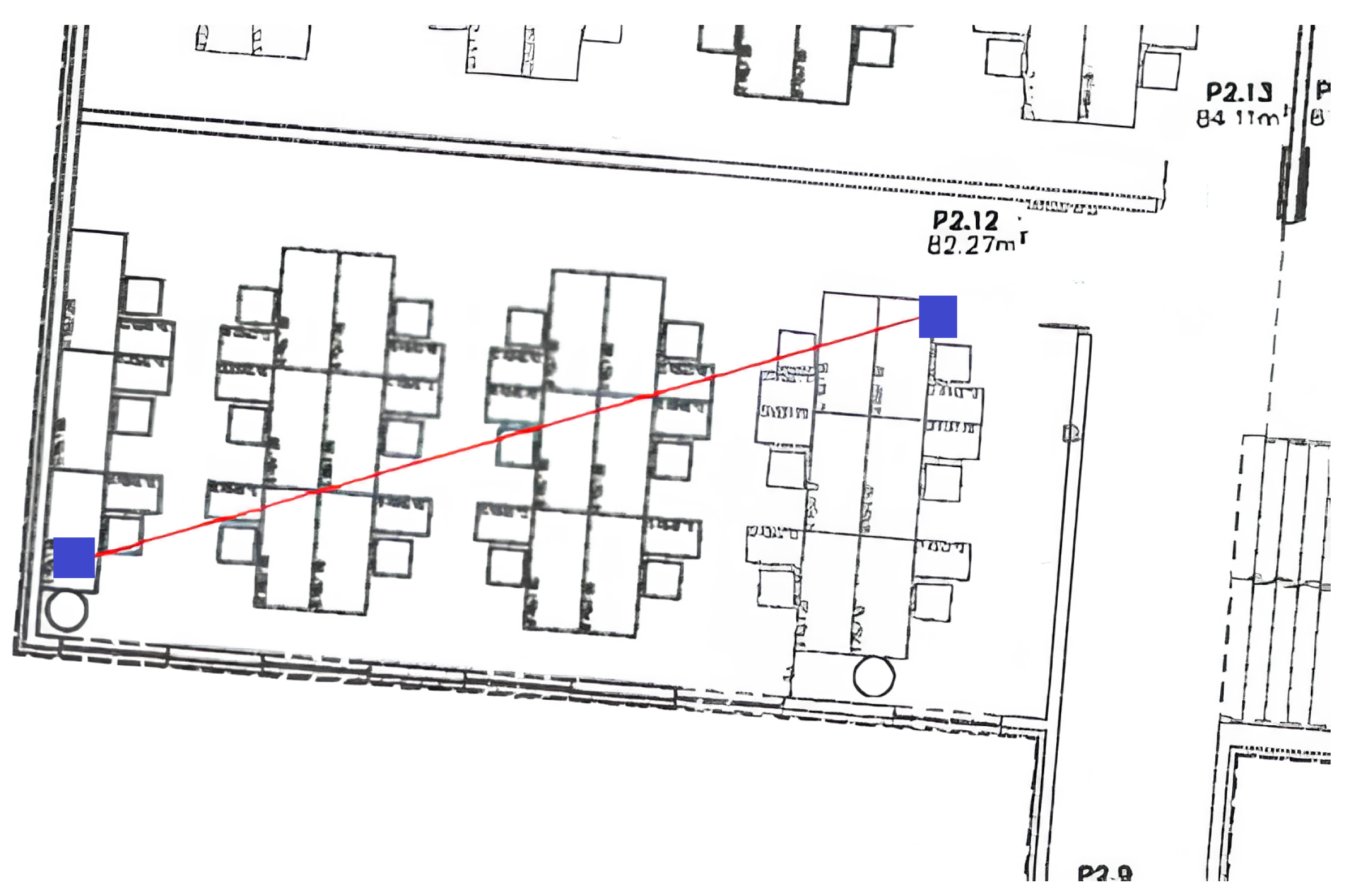
  • Building with obstacles. This is an indoor office scenario, where the bridge and the IoT devices were separated by many desktops and electronic devices. There was only one transmitter and one receiver. The IoT devices and bridge were located inside a drawer to make communications even more difficult, thus simulating the existence of additional obstacles. Additional obstacles in the environment included people and IT equipment (PCs, routers, monitors). Drawers and other furnishings were primarily made of wood. Most of the obstacles have right angles and flat surfaces. The devices were positioned approximately 2 m below the ceiling. Figure 7 shows a blueprint of this scenario.
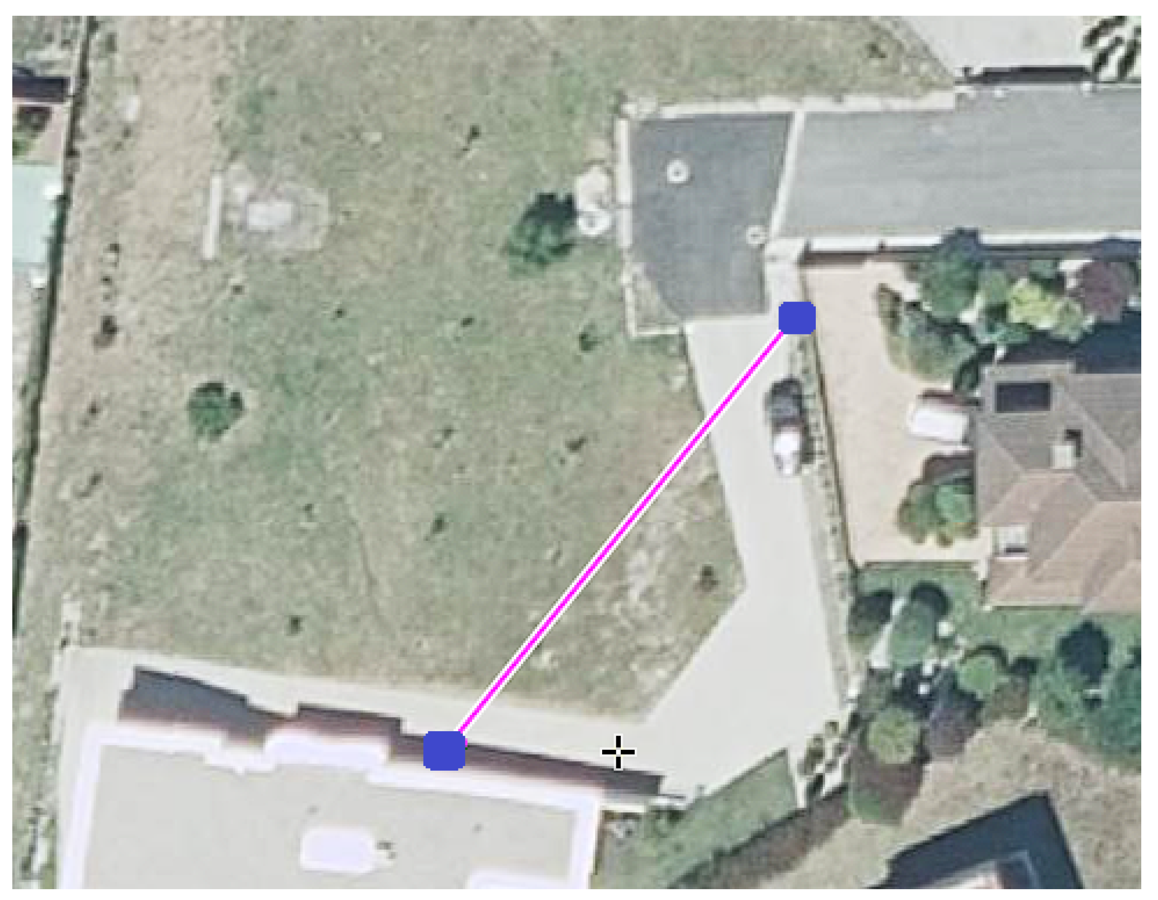
  • Outdoor scenario. All IoT devices were positioned in the same location, at a height of approximately 25 cm, and they were separated from the bridge by 25 m (the bridge was at a height of roughly 1 m). The ground that separates the bridge and the IoT devices was slightly inclined, but there was a Line of Sight (LoS) between the transmitters and the receiver. There were no physical barriers or obstructions between the devices, and the density of electronic devices is minimized to reduce the risk of interference. Also, there are no people, vehicles, or obstacles between devices. As an outdoor scenario, there was no ceiling. Each device, at the opposite path from the other device, had a rock wall that may absorb part of the signal, but also create reflections that generate multiple paths; this may lead to overlapping, producing constructive or destructive interferences. This scenario aims to measure the performance of the proposed protocol over long distances in an environment with minimal obstacles and reduced reflection sources. Figure 8 shows a satellite view of this scenario.
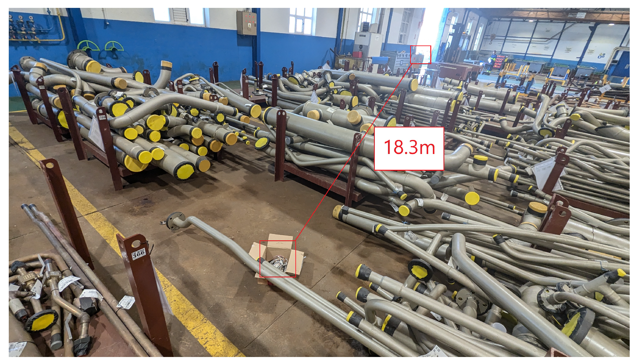
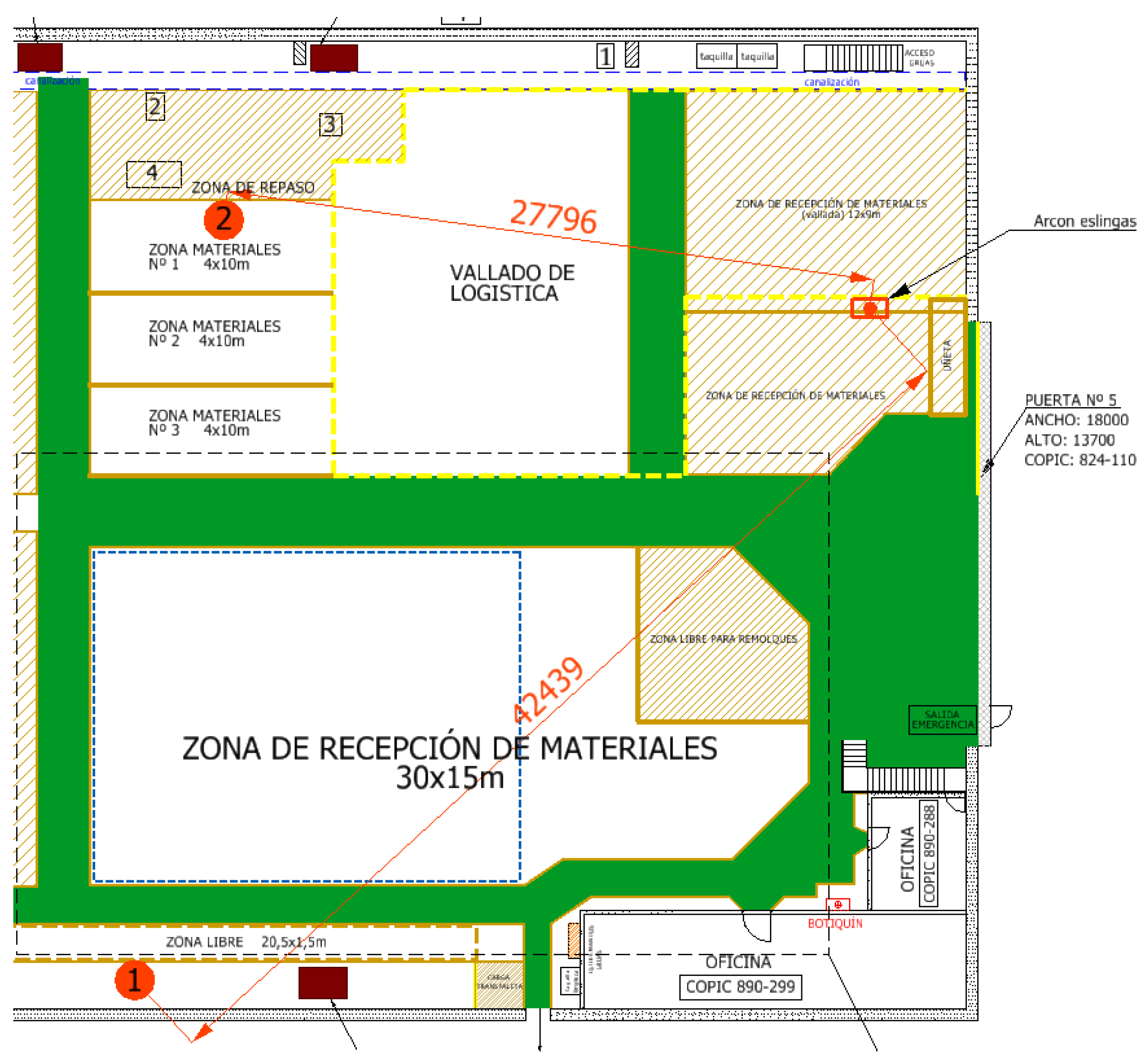
  • Industrial scenario. Some tests were performed in an industrial workshop with the presence of heavy machinery and metal objects. Specifically, the place where the tests were carried out was the facilities of Navantia in Ferrol (Spain). Navantia is one of the ten largest shipbuilders in the world. Actually, the goal of this set of experiments was to evaluate the performance of the proposed protocol to locate objects used by industrial operators for their shipbuilding tasks and also track some parameters from a vast set of objects, being scalable and power efficient. Figure 9 and Figure 10 show the location of the devices and distance between them, while Figure 11, shows a blueprint with the different positions of the devices and distance between them. This is a NLoS scenario. The devices were located at a 1–1.5 m height, and the ceiling is at approximately 10 m distance. Different distances and obstacle densities were tested. During the tests, industrial operators, electronic devices, and machinery were moving between both IoT devices, as in a regular working day in the workshop. This scenario is very demanding due to the high presence of metal obstacles, which notably reduces the quality of the signal received. As there were a vast amount of obstacles, the surface of the environment is not flat, causing more interferences, different reflections and multipath.

4.1.4. Configurable Parameters

Depending on the characteristics of the scenario, the protocol may require the adjustment of certain parameters to either maximize bandwidth or minimize beacon loss rates.
For the performed experiments, all IoT devices were configured to have the same transmission interval for beacons, while the bridge would scan beacons during the same interval. The beaconing intervals were 100 ms, 200 ms, 500 ms, 1000 ms, 3000 ms, 5000 ms and 10,000 ms.
Three different transmission power levels were tested: 0 dBm, +9 dBm and +21 dBm. The default value was 0 dBm, and not every board was capable of transmitting or receiving at +21 dBm. Increasing the power level leads to better coverage at the cost of power consumption.

4.2. Experimental Results

4.2.1. Advertisement Interval Distribution

These tests determined the percentage of beacons transmitted on time and lost. Five possibilities were considered when a new beacon was received:
  • Same value. When the received value was identical to the previous one, this would mean the receiver was not able to receive the current beacon but did receive a beacon before the sender updated the counter value. By default, it is not possible for a bridge to receive the same beacon from the same sender more than once, but in this case, this is possible because the bridge forgets the last beacon received in order to increase the frequency of receiving them. In addition, the hash table mentioned in Section 3.3 was not used for these tests, as the aim of the test is to measure how often these situations occur. It must be noted that sending a beacon is not something that happens instantly, as happens with GATT communications; the beacon is continuously emitted during the advertisement interval.
  • Correct value. The received value was exactly one unit higher than the previous value received from that sender.
  • Value higher than 2 units. One intermediate beacon was lost, or the transmitter ended its sending interval before expected.
  • Value higher in more than 2 units. Between the transmissions of two beacons, more than one beacon was lost.
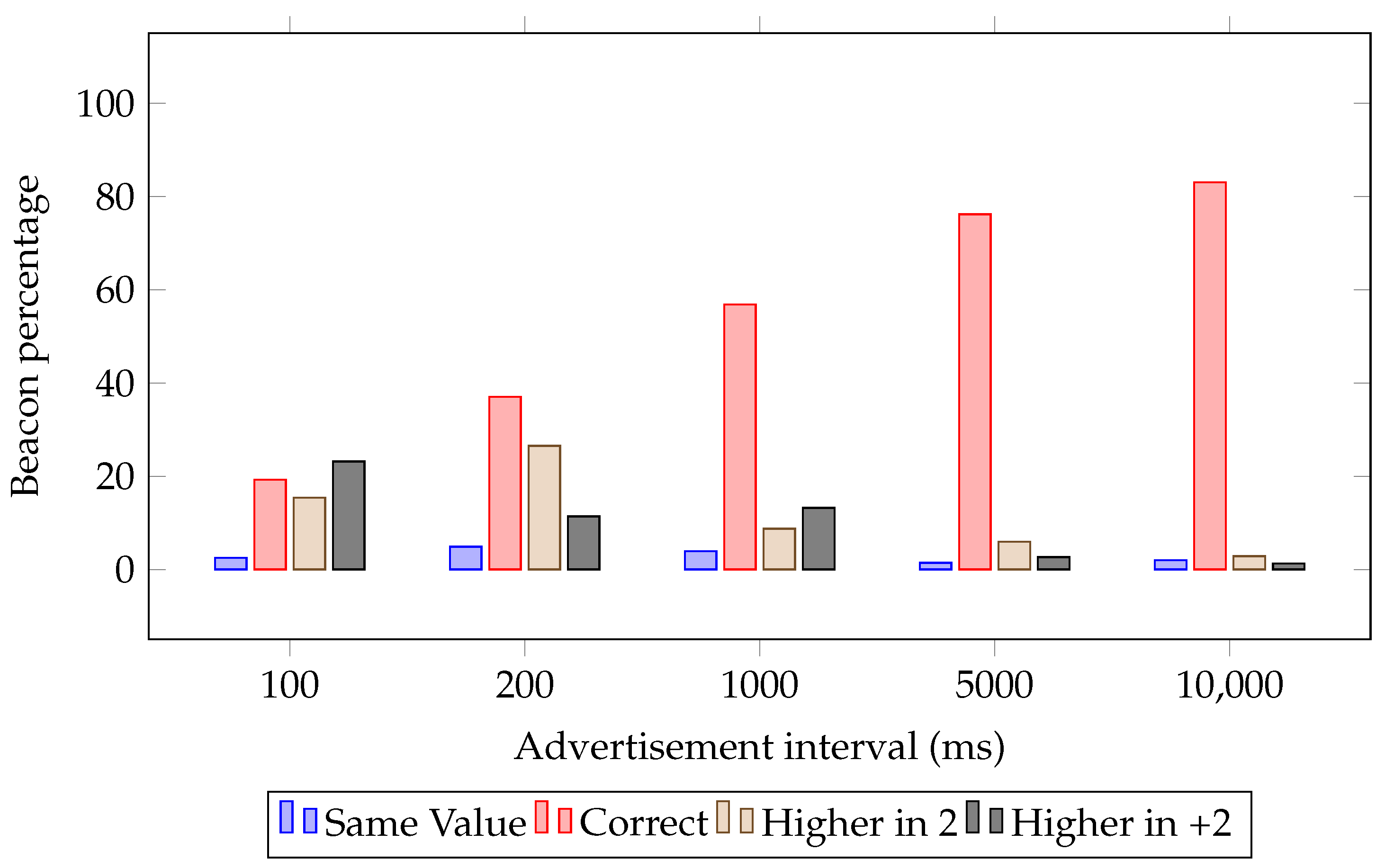
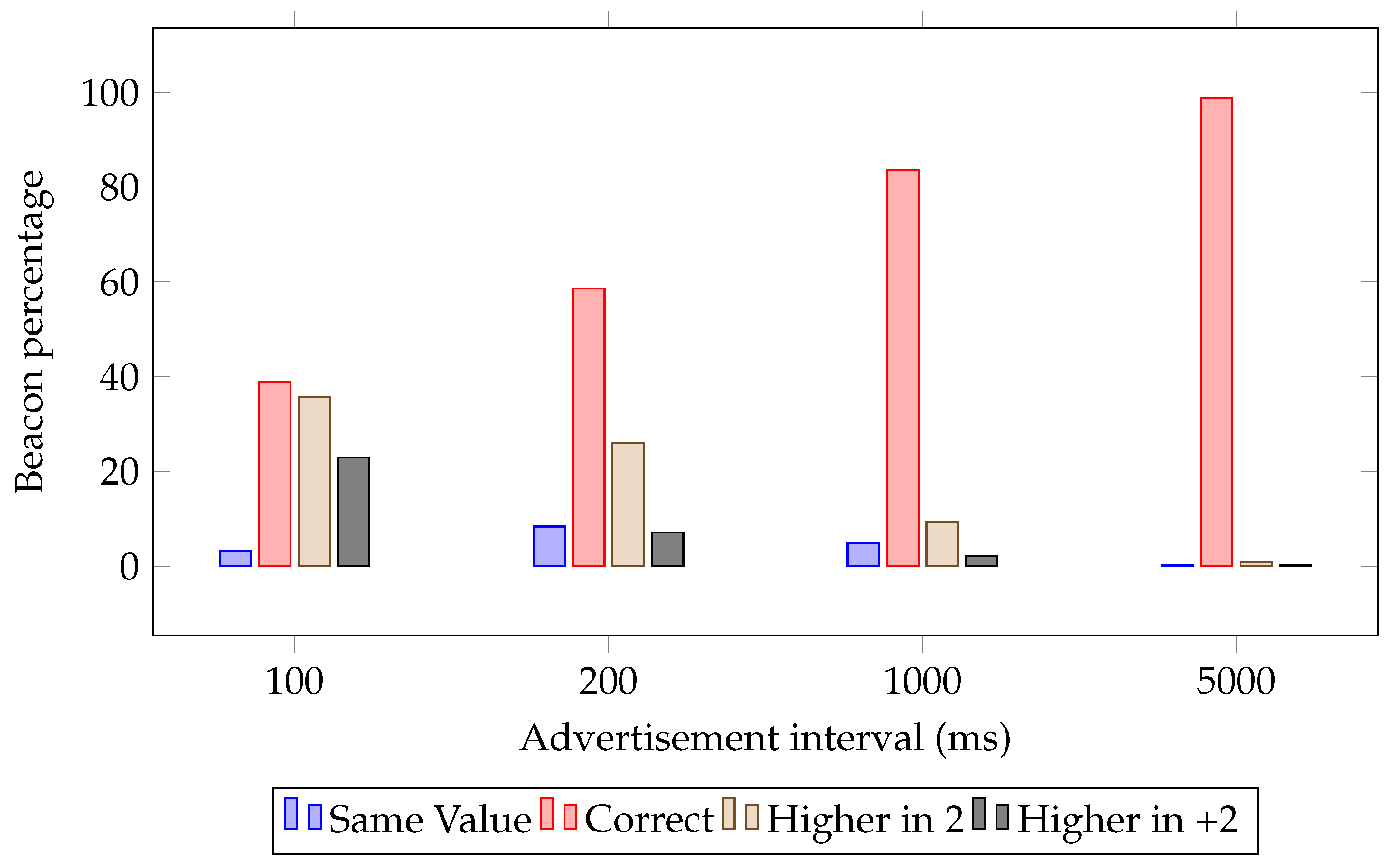
For each test, Figure 12, Figure 13 and Figure 14 show the percentage of beacons in the Y-axis and the different advertisement interval times in the X-axis. The devices that were used for this test are the ESP32, without the version 5 of Bluetooth.
The tests conducted on the nearby devices scenario are shown in Figure 12. As it can be observed, the percentage of beacons received varies from 57.71% for the test with a 100 ms transmission interval to 95% when using a 1 s interval. For the 100 ms and 200 ms scenario, most of the beacons had a correct value: 57.71% and 74.48%, respectively, but 19.05% and 14.55% were higher in 2, respectively, meaning that it is common to skip 1 beacon when using these intervals. For the higher in more than 2 values (Higher in +2), this happens for 4.06% and 0.34% of beacons, respectively, so consecutively lost beacons are uncommon when using an interval larger than 200 ms. This test shows the limitation of using the default transmission power level and non-Bluetooth 5 hardware when the advertisement interval is less than a second.
For the test conducted in a home with the presence of obstacles (whose results are represented in Figure 13), most of the beacons have a higher value than expected for intervals of 100 and 200 ms. This situation changes when the transmission interval is 1 s or longer. For the 100 ms case, only 19.27% of the beacons had the expected value, while 23.18% are higher than expected in more than 2 units (Higher in +2). This indicates that, at these advertisement intervals, a significant number of consecutive data packets are lost. A 1000 ms advertisement interval was needed to get at least half of the beacon values correct, while a 10,000 ms advertisement interval leads to 83.00% of correct beacon values. The majority of the obstacles for this test are concrete walls and wooden furniture, so it can be concluded that these materials produce a considerable amount of reflections, as they absorb part of the signal.
For the outdoor test, the obtained results are shown in Figure 14. It can be observed that, from 200 ms onwards, most data were received correctly. For 5000 ms, almost all data are received correctly. For the 100, 200 and 1000 ms cases, values higher in 2 were found in 35.77%, 25.95% and 9.35% of beacons, respectively, and values higher in more than 2 occurred in 22.97%, 7.09% and 2.15% of beacons respectively. The 10,000 ms case was not tested, as the 5000 milliseconds advertisement interval offered a 98.77% of correct values. This test concludes that these beacons are less vulnerable from distance than obstacles, as increasing the advertisement interval notably reduces the lost data.
Part of the incorrect data detected in the previous tests was caused by the fact that the used ESP32 boards are not capable of receiving certain beaconing data: even though the receivers attempted to collect beacons every 100 milliseconds, they actually received them every 70–130 ms.
Regarding the amount of data not received, the test reaches almost perfect results from the 5000 ms interval onwards, except for the home scenario with obstacles. In such a scenario, it seems that signal reflections prevent some beacons from being received despite having ample time available.
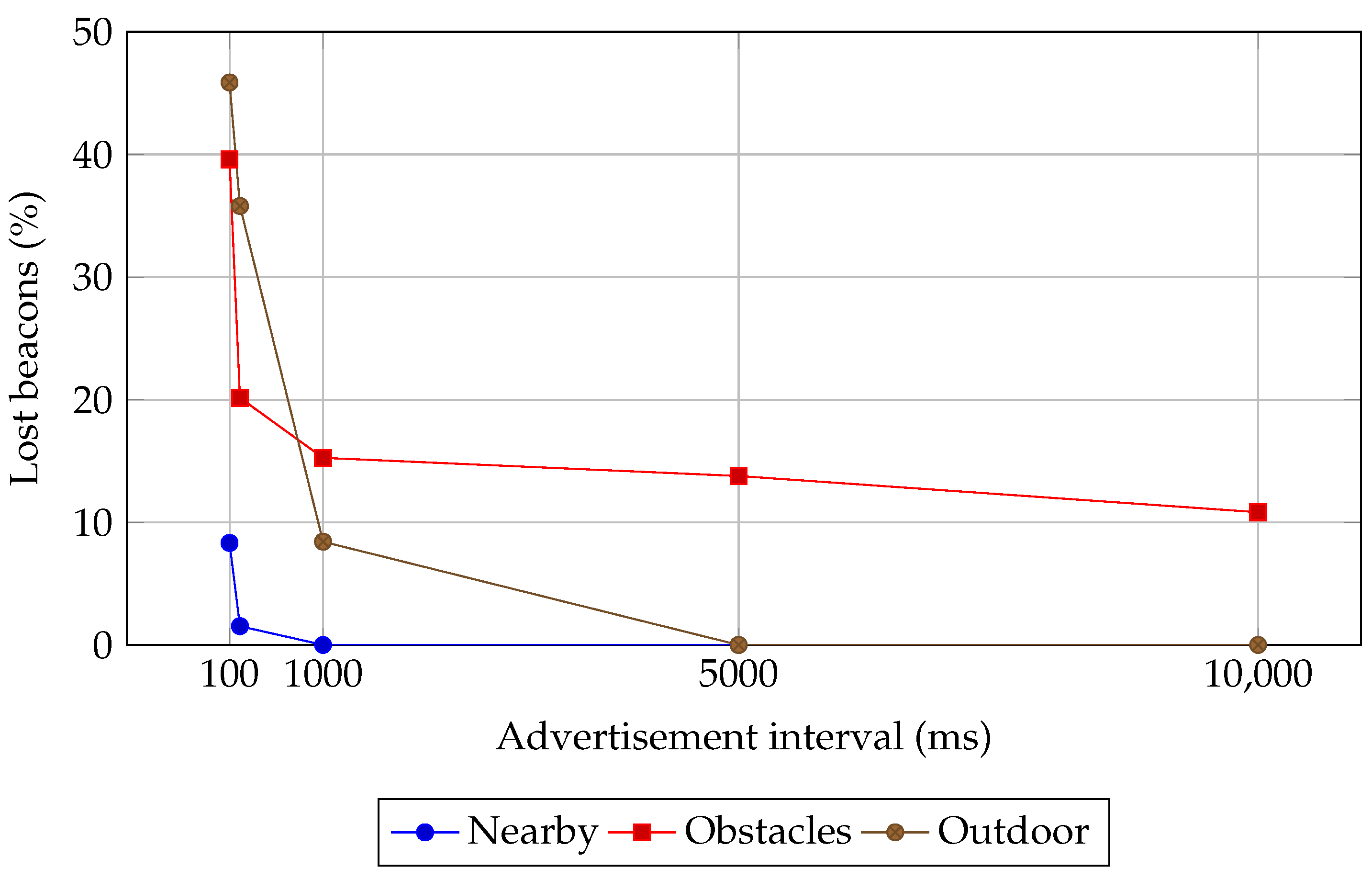
Finally, it is important to note that, in the Figures previously mentioned in this subsection, the sum of the percentages is usually less than 100%, since the lost beacons are not represented. Such a percentage is summarized in Figure 15, which indicates it for the different evaluated scenarios. The scenario with less lost beacons is the nearby scenario, as having short distances and no presence of obstacles ensures less signal reflections. For the 100 ms and 200 ms, the amount of not received beacons is 8.32% and 1.53%, respectively, no beacons were lost for intervals larger than 1000 ms. At the obstacles scenario, not received beacons start at 39.60% with 100 ms interval, 20.15% with 200 ms interval and 10.82% for 100,000 ms interval. For the outdoor scenario, not received beacons are slightly more than in obstacles scenario for 100 and 200 ms interval, but 0% from 5000 ms onwards. The results clearly show a great improvement between 100 ms and 200 ms.

4.2.2. Impact of Transmission Power Level and Advertisement Interval for Different IoT Nodes

Tests were performed in different scenarios for diverse transmission power levels and advertisement intervals. Moreover, the different underlying IoT node hardware was tested in order to determine its performance.
In a scenario full of obstacles inside a building, the tests were carried out for both ESP32 and ESP32S3-based IoT nodes, evaluating different advertisement intervals and transmission power levels.
Figure 16 shows a comparison on the performance of different devices and transmission power levels. As expected, the ESP32S3 provides a better data reception, as it takes advantage of Bluetooth 5 technology, which ensures a larger coverage and improved autonomy. Increasing the transmission power level is another method for collecting more correct beacons. In addition, it can be observed that the tests completed with a 1 s advertisement interval got a result of 0% lost beacons for every power level on ESP32S3 devices.
The tests were also performed in the previously described industrial environment, in the scenario illustrated in Figure 10. As Table 2 indicates, these tests were carried out with two different ESP32 boards at their maximum transmission power level, with an advertisement interval of 200 ms and 3000 ms and with different densities of obstacles.
The first set of tests was performed in an scenario with 18.3 m of distance between the transmitter and the receiver, and with presence of multiple metal obstacles. In such a scenario, the advertisement interval was 200 ms and the antenna/transmission power level was +9 dBm, using the ESP32 board. The result was that 93.72% of the transmitted beacons were received correctly. Such a percentage rises to 100% when increasing the advertisement interval to 3 s.
The second test was carried out at 21 m of distance but less obstacles were present. In such a situation, 95.82% of the beacons were received correctly with a 3 s advertisement interval and +9 dBm for antenna/transmission power level.
The third test used an ESP32S3 board with +21 dBm of transmission power. For a 27.8 m distance, a medium level of obstacles and a 200 ms advertisement interval, the beacon reception rate was 78.66%. In contrast, the result for a lower transmission power (+9 dBm) was only 46.99%.
The final test was performed with another ESP32S3 board, which in this case acted as a receiver, but it was connected to an external antenna (the transmitter was the same as in the previous experiments). The distance between the two IoT devices was 42.4 m and there was a high level of obstacles. Moreover, the transmission power was set to +21 dBm and the advertisement interval to 200 ms. In such a scenario, the percentage of correctly received beacons was 80.66%. Using the same setup, measurements were repeated, but when the receiver did not use the external antenna, it received less than 0.1% of the transmitted beacons.
Similar tests were performed in the outdoor scenario (which does not have line-of-sight obstacles), aiming to estimate the maximum range for this communication protocol. The tests included all the devices previously mentioned and are summarized in Table 3. As can be observed, when the evaluated IoT device made use of the external antenna, the maximum range was extended, although it lost approximately 10% of the beacons for a test at a 100 m distance with a 200 ms advertisement interval. For the rest of the devices, data reception was acceptable for a 40–60 m distance when using a +9 dBm or +21 dBm transmission power (note that the test at a 61 m distance was made with a 200 ms advertisement interval: after repeating the experiments for a 1-s advertisement interval, the percentage of correctly received beacons rose to 81.39%).

5. Key Findings

The following are the most relevant key findings that can be drawn from this article:
  • The communication protocol presented in this article is designed for IoT telemetry systems that require low consumption. Compared with the original Eddystone-TLM standard, this protocol reduces many limitations, such as the restriction to a single beacon per second per device and the maximum payload per frame. The protocol is designed to be customizable using different frame types for heterogeneous devices, while still maintaining compatibility with the standard Eddystone-TLM beacon.
  • The performed experiments allowed for validating the use of the protocol in the selected evaluation scenarios. For instance, in the nearby scenario, more than 90% of the emitted data were received for a 100 ms advertisement interval, meaning an effective data rate of 9 received beacons per second for each device, in contrast to the maximum of only one when using the Eddystone-TLM standard. For a 25 m distance, data loss was approximately 36% for a 200 ms advertisement interval, still granting a higher effective data rate than the original protocol.
  • Some of the evaluated IoT nodes proved to offer clearly better results, like when using Bluetooth 5 hardware and an external antenna with +21 dBm, which led to almost 90% data reception for a 100 m distance (when using the same advertisement interval). Such IoT nodes were also effective for scenarios with a high presence of metal obstacles, where increasing the advertisement interval is not enough for receiving more than 90% of the emitted data. For instance, in the industrial scenario, the previously mentioned hardware obtained roughly 80% of the data received at a 42 m distance with a 200 ms advertisement interval (i.e., four beacons were actually received beacons per second). These results can be further enhanced by the ability to transmit up to three parameters per beacon when employing data compression techniques.
  • The effectiveness of the proposed protocol is demonstrated for diverse contexts, including industry environments, indoor and outdoor scenarios. For instance, the results from the previous section show that beacon loss is minimal in scenarios with short distances and few obstacles.
  • Ideal conditions are not always present in real-world deployments. To keep a high bandwidth under challenging conditions, there are different strategies. The first one involves utilizing the latest hardware, equipped with Bluetooth 5.0 or newer, which leads to lower power consumption and reduces data loss. When the objective is to maximize bandwidth, reducing the advertisement interval has proven effective, as it allows for the emission of updated data with the lowest latency. In long-distance scenarios, increasing the advertisement interval can help reduce beacon loss. However, this approach may be insufficient in environments with thick obstacles and rough surfaces that significantly cause signal attenuation. In such cases, increasing the transmission power level is an effective solution. Finally, in harsh environments where long-distance communications must occur in the presence of obstacles, using external antennas can significantly enhance performance.
  • The experimental tests validated the functionality of the proposed protocol, demonstrating notable improvements in data rate achieved by reducing beacon transmission intervals. Specifically, the results indicate that newer hardware utilizing Bluetooth 5 not only offers broader coverage compared with earlier versions but also provides lower power consumption. Moreover, the proposed protocol can take advantage of increasing the transmission power level to increase data reception at the cost of more energy consumption. Furthermore, the use of an external antenna can significantly extend the operating range of the proposed protocol. While this extended range may not be necessary in all scenarios, using a single device for receiving data from all the transmitters deployed in a large area reduces the number of receiver devices needed. Deploying more receivers in the same area can also provide fine-grained information about the location of the devices.
  • It is worth noting that the presented experiments evaluated performance in each environment using packet loss as the primary metric, without relying on empirical models, as several existing studies have already explored that approach. For instance, a relevant study about BLE 5 and how distances affect its range for indoor environments is found in [75], where authors measure the Received Signal Strength Indicator (RSSI) for different positions inside a building. A more in-depth analysis is performed in [76] for RSSI and how transmission power affects connectivity for the previous BLE version 4. On Low-Power Wide-Area Network (LPWAN) communications, the studies [77,78] use empirical models and equations for measuring the signal strength at different scenarios. These models cannot apply to this study, as they are designed for >1 km distances, while the performed experiments took place on <100 m scenarios.
  • With respect to future work, it is worth noting that this article is not focused on providing an in-depth analysis of the energy consumption of the proposed protocol and architecture. Therefore, a natural extension of this research would be to compare the power usage of the proposed protocol against the standard Eddystone-TLM when running on identical devices. In addition, it would be valuable to quantify the additional energy cost associated with techniques such as increasing transmission power or utilizing larger antennas.

6. Conclusions

This article introduced a novel protocol that facilitates communication among multiple heterogeneous IoT devices, providing low latency and more information per beacon. In addition, the devised protocol allows for a flexible configuration, enabling adjustments to beacon advertisement intervals and transmission power levels based on specific scenarios and their requirements. Moreover, the protocol accommodates the inclusion of new opportunistic IoT devices and new parameters by simply adding options to the bridge and by defining data compression methods. To ensure full coverage, the BLE bridge operates in a distributed manner, enabling communications with IoT nodes regardless of their location.
The proposed protocol for opportunistic data collection was extensively tested in diverse real-world environments, including home, office, outdoor, and industrial scenarios (e.g., a shipyard of Navantia), demonstrating robust performance across varying distances and obstructions, and examining different strategies to keep its good performance under challenging real-world deployments.

Author Contributions

Conceptualization, P.F.-L. and T.M.F.-C.; methodology, P.F.-L. and T.M.F.-C.; investigation, P.G.-R., Á.N.-M., P.F.-L. and T.M.F.-C.; writing—original draft preparation, P.G.-R., Á.N.-M., P.F.-L. and T.M.F.-C.; writing—review and editing, P.F.-L. and T.M.F.-C.; supervision, P.F.-L. and T.M.F.-C.; project administration, T.M.F.-C.; funding acquisition, T.M.F.-C. All authors have read and agreed to the published version of the manuscript.

Funding

This work has been supported by Centro Mixto de Investigación UDC-NAVANTIA (IN853C 2022/01), funded by GAIN (Xunta de Galicia) and ERDF Galicia 2021–2027. In addition, this work has been supported by the grant PID2020-118857RA-100 (ORBALLO) funded by MCIN/AEI/10.13039/501100011033.

Institutional Review Board Statement

Not applicable.

Informed Consent Statement

Not applicable.

Data Availability Statement

The original contributions presented in this study are included in the article. Further inquiries can be directed to the corresponding author(s).

Acknowledgments

We would like to thank the Navantia personnel who collaborated with us during the tests carried out in the shipyard workshops. A special mention should be addressed to the support provided by Esteban López Lodeiro and Juan M. Varela Antelo.

Conflicts of Interest

The authors declare no conflict of interest.

References

  1. Demandsage. How Many IoT Devices Are There (2025–2030). Available online: https://www.demandsage.com/number-of-iot-devices/ (accessed on 8 July 2025).
  2. Hernández-Rojas, D.; Fernández-Caramés, T.; Fraga-Lamas, P.; Escudero, C. A Plug-and-Play Human-Centered Virtual TEDS Architecture for the Web of Things. Sensors 2018, 18, 2052. [Google Scholar] [CrossRef] [PubMed]
  3. Fraga-Lamas, P.; Barros, D.; Lopes, S.I.; Fernández-Caramés, T.M. Mist and Edge Computing Cyber-Physical Human-Centered Systems for Industry 5.0: A Cost-Effective IoT Thermal Imaging Safety System. Sensors 2022, 22, 8500. [Google Scholar] [CrossRef] [PubMed]
  4. Niebla-Montero, A.; Froiz-Míguez, I.; Fraga-Lamas, P.; Fernández-Caramés, T.M. Practical Latency Analysis of a Bluetooth 5 Decentralized IoT Opportunistic Edge Computing System for Low-Cost SBCs. Sensors 2022, 22, 8360. [Google Scholar] [CrossRef] [PubMed]
  5. Niebla-Montero, A.; Froiz-Míguez, I.; Fraga-Lamas, P.; Fernández-Caramés, T.M. Design, Implementation and Practical Evaluation of an Opportunistic Communications Protocol Based on Bluetooth Mesh and libp2p. Sensors 2025, 25, 1190. [Google Scholar] [CrossRef]
  6. Ayele, E.D.; Meratnia, N.; Havinga, P.J. Towards a New Opportunistic IoT Network Architecture for Wildlife Monitoring System. In Proceedings of the 2018 9th IFIP International Conference on New Technologies, Mobility and Security (NTMS), Paris, France, 26–28 February 2018; pp. 1–5. [Google Scholar] [CrossRef]
  7. Huang, X.; Yu, R.; Liu, J.; Shu, L. Parked Vehicle Edge Computing: Exploiting Opportunistic Resources for Distributed Mobile Applications. IEEE Access 2018, 6, 66649–66663. [Google Scholar] [CrossRef]
  8. Max-Onakpoya, E.; Madamori, S.; Baker, C.E. Utilizing Opportunistic Social Networks for Remote Patient Monitoring in Rural Areas. In Proceedings of the 1st ACM International Workshop on Technology Enablers and Innovative Applications for Smart Cities and Communities, New York, NY, USA, 13–14 November 2019; TESCA’19. pp. 46–49. [Google Scholar] [CrossRef]
  9. Silva, R.; Silva, J.S.; Boavida, F. Opportunistic fog computing: Feasibility assessment and architectural proposal. In Proceedings of the 2017 IFIP/IEEE Symposium on Integrated Network and Service Management (IM), Lisbon, Portugal, 8–12 May 2017; pp. 510–516. [Google Scholar] [CrossRef]
  10. Mohamed, N.; Al-Jaroodi, J.; Jawhar, I.; Noura, H.; Mahmoud, S. UAVFog: A UAV-based fog computing for Internet of Things. In Proceedings of the 2017 IEEE SmartWorld, Ubiquitous Intelligence & Computing, Advanced & Trusted Computed, Scalable Computing & Communications, Cloud & Big Data Computing, Internet of People and Smart City Innovation (SmartWorld/SCALCOM/UIC/ATC/CBDCom/IOP/SCI), San Francisco, CA, USA, 4–8 August 2017; pp. 1–8. [Google Scholar] [CrossRef]
  11. Chamarajnagar, R.; Ashok, A. Opportunistic Mobile IoT with Blockchain Based Collaboration. In Proceedings of the 2018 IEEE Global Communications Conference (GLOBECOM), Abu Dhabi, United Arab Emirates, 10–12 December 2018; pp. 1–6. [Google Scholar] [CrossRef]
  12. Fernández-Caramés, T.M.; Fraga-Lamas, P. Design of a Fog Computing, Blockchain and IoT-Based Continuous Glucose Monitoring System for Crowdsourcing mHealth. Proceedings 2019, 4, 37. [Google Scholar] [CrossRef]
  13. Bluetooth. Bluetooth 5.4 Specification. Available online: https://www.bluetooth.com/bluetooth-resources/bluetooth-core-specification-version-5-4-technical-overview/ (accessed on 15 July 2025).
  14. Yaakop, M.B.; Abd Malik, I.A.; bin Suboh, Z.; Ramli, A.F.; Abu, M.A. Bluetooth 5.0 throughput comparison for internet of thing usability a survey. In Proceedings of the 2017 International Conference on Engineering Technology and Technopreneurship (ICE2T), Kuala Lumpur, Malaysia, 18–20 September 2017; pp. 1–6. [Google Scholar] [CrossRef]
  15. Enriko, I.K.A.; Gustiyana, F.N. Wi-Fi HaLow: Literature Review About Potential Use of Technology in Agriculture and Smart Cities in Indonesia. In Proceedings of the 2024 International Conference on Green Energy, Computing and Sustainable Technology (GECOST), Miri Sarawak, Malaysia, 17–19 January 2024; pp. 277–281. [Google Scholar] [CrossRef]
  16. Webpage, T.G.O. Thread Group Official Webpage. Available online: https://www.threadgroup.org (accessed on 4 July 2025).
  17. Tupas Castro, C.M.; Sharma, A.; Sampath Kumar, D.; Abidi, K.; Kim, N. The implementation of Thread Network for a Smart Factory. In Proceedings of the 2022 IEEE Symposium Series on Computational Intelligence (SSCI), Singapore, 4–7 December 2022; pp. 253–260. [Google Scholar] [CrossRef]
  18. Jaisinghani, D.; Rehman, T.U.; Mulkey, R.; Berns, A. IoT in the Air: Thread-Enabled Flying IoT Network for Indoor Environments. In Proceedings of the 2023 IEEE International Conference on Pervasive Computing and Communications Workshops and other Affiliated Events (PerCom Workshops), Atlanta, GA, USA, 13–17 March 2023; pp. 142–147. [Google Scholar] [CrossRef]
  19. IQRF Alliance. Available online: https://www.iqrfalliance.org/index.php (accessed on 4 July 2025).
  20. Bouzidi, M.; Gupta, N.; Dalveren, Y.; Mohamed, M.; Alaya Cheikh, F.; Derawi, M. Indoor Propagation Analysis of IQRF Technology for Smart Building Applications. Electronics 2022, 11, 3972. [Google Scholar] [CrossRef]
  21. Gkagkas, G.; Vergados, D.J.; Michalas, A. The advantage of the 5G network for enhancing the Internet of Things. In Proceedings of the 2021 6th South-East Europe Design Automation, Computer Engineering, Computer Networks and Social Media Conference (SEEDA-CECNSM), Preveza, Greece, 24–26 September 2021; pp. 1–7. [Google Scholar] [CrossRef]
  22. Petrenko, A.S.; Petrenko, S.A.; Makoveichuk, K.A.; Chetyrbok, P.V. The IIoT/IoT device control model based on narrow-band IoT (NB-IoT). In Proceedings of the 2018 IEEE Conference of Russian Young Researchers in Electrical and Electronic Engineering (EIConRus), Moscow and St. Petersburg, Russia, 29 January–1 February 2018; pp. 950–953. [Google Scholar] [CrossRef]
  23. Insteon Official Webpage. Available online: https://www.insteon.com (accessed on 4 July 2025).
  24. EnOcean Alliance. Available online: https://enocean-alliance.org (accessed on 4 July 2025).
  25. X10. Available online: https://www.x10.com/pages/allaboutx10 (accessed on 4 July 2025).
  26. Wi-Sun Official Webpage. Available online: https://wi-sun.org/ (accessed on 4 July 2025).
  27. Scaramella, G.; Heck, G.C.; Lippmann Junior, L.; Hexsel, R.A.; Santana, T.; Gomes, V.B. Enabling LoRaWAN Communication Over Wi-SUN Smart Grid Networks. In Proceedings of the ICC 2022—IEEE International Conference on Communications, Seoul, Republic of Korea, 16–20 May 2022; pp. 4842–4847. [Google Scholar] [CrossRef]
  28. Extended Coverage-GSM-Internet of Things (EC-GSM-IoT). Available online: https://www.gsma.com/solutions-and-impact/technologies/internet-of-things/extended-coverage-gsm-internet-of-things-ec-gsm-iot/ (accessed on 4 July 2025).
  29. Weber, B.; Korb, M.; Tschopp, D.; Altorfer, S.; Rogin, J.; Kröll, H.; Huang, Q. A SAW-less RF-SoC for cellular IoT supporting EC-GSM-IoT -121.7 dBm sensitivity through EGPRS2A 592 kbps throughput. In Proceedings of the ESSCIRC 2017—43rd IEEE European Solid State Circuits Conference, Leuven, Belgium, 11–14 September 2017; pp. 340–343. [Google Scholar] [CrossRef]
  30. Ingenu Official Webpage. Available online: https://www.ingenu.com/technology/rpma/ (accessed on 4 July 2025).
  31. Nashiruddin, M.I.; Winalisa, S.; Nugraha, M.A. Random Phase Multiple Access Network for Public Internet of Things in Batam Island. In Proceedings of the 2021 8th International Conference on Electrical Engineering, Computer Science and Informatics (EECSI), Semarang, Indonesia, 20–21 October 2021; pp. 311–316. [Google Scholar] [CrossRef]
  32. Waviot Official Webpage. NB-Fi Specification. Available online: https://waviot.com/technology/nb-fi-specification/ (accessed on 4 July 2025).
  33. Bankov, D.; Levchenko, P.; Lyakhov, A.; Khorov, E. On the Limits and Best Practice for NB-Fi: A New LPWAN Technology. IEEE Internet Things J. 2023, 10, 12352–12365. [Google Scholar] [CrossRef]
  34. Mioty Alliance Official Webpage. Available online: https://mioty-alliance.com/ (accessed on 4 July 2025).
  35. Mandal, D.; Banerjee, S. Surface Acoustic Wave (SAW) Sensors: Physics, Materials, and Applications. Sensors 2022, 22, 820. [Google Scholar] [CrossRef]
  36. Shah, S.; Koley, S.; Malandra, F. Experimental End-To-End Delay Analysis of LTE Cat-M with High-Rate Synchrophasor Communications. IEEE Internet Things J. 2023, 10, 19839–19848. [Google Scholar] [CrossRef]
  37. Wize Alliance. Technical Documents. 2024. Available online: https://www.wize-alliance.com/Downloads/Technical (accessed on 4 July 2025).
  38. Niebla-Montero, A.; Froiz-Míguez, I.; Fraga-Lamas, P.; Fernández-Caramés, T.M. Practical Evaluation of Wize and Bluetooth 5 Assisted RFID for an Opportunistic Vehicular Scenario. In Proceedings of the 2024 IEEE International Conference on RFID (RFID), Cambridge, MA, USA, 4–6 June 2024; pp. 101–106. [Google Scholar] [CrossRef]
  39. Arnaud, A.; Costa, G. Ultra low-cost sensors using RFID standards for data collection, for IoT systems in food production and logistics. In Proceedings of the 2020 IEEE 11th Latin American Symposium on Circuits & Systems (LASCAS), San Jose, Costa Rica, 25–28 February 2020; pp. 1–4. [Google Scholar] [CrossRef]
  40. NFC Forum. Specifications. 2024. Available online: https://nfc-forum.org/ (accessed on 4 July 2025).
  41. Gawade, D.R.; Roy Simorangkir, B.V.B.; Kumar, S.; Pigeon, M.; Belcastro, M.; Rather, N.; Buckley, J.L.; O’Flynn, B. A Battery-less NFC Sensor Transponder for Cattle Health Monitoring. In Proceedings of the 2023 IEEE Applied Sensing Conference (APSCON), Bengaluru, India, 23–25 January 2023; pp. 1–3. [Google Scholar] [CrossRef]
  42. Bluetooth Technology Website. Specifications. 2024. Available online: https://www.bluetooth.com/specifications/specs/ (accessed on 4 July 2025).
  43. García-Rivada, P.; Fraga-Lamas, P.; Fernández-Caramés, T. An Intelligent IoT Wearable for Monitoring and Preventing Asthma Attacks. In Proceedings of the VI Congreso XoveTIC: Impulsando el Talento Científico, A Coruña, Spain, 5–6 October 2023; pp. 263–268. [Google Scholar] [CrossRef]
  44. Fré, G.; Erman, B.; Martino, C.D. Data Shower in Electronics Manufacturing: Measuring Wi-Fi 4, Wi-Fi 6, and 5G SA behavior in production assembly lines. In Proceedings of the 2023 53rd Annual IEEE/IFIP International Conference on Dependable Systems and Networks—Supplemental Volume (DSN-S), Porto, Portugal, 27–30 June 2023; pp. 14–20. [Google Scholar] [CrossRef]
  45. Stankevich, S.A.; Lubskyi, M.S.; Lysenko, A.R. Long-wave infrared remote sensing data spatial resolution enhancement using modulation transfer function fusion approach. In Proceedings of the 2021 International Conference on Information and Digital Technologies (IDT), Zilina, Slovakia, 22–24 June 2021; pp. 89–94. [Google Scholar] [CrossRef]
  46. UWB Alliance. UWB Alliance Official Website. 2024. Available online: https://uwballiance.org/ (accessed on 4 July 2025).
  47. Kopta, V.; Enz, C. Ultra-Low Power FM-UWB Transceivers for IoT; River Publishers: Boca Raton, FL, USA, 2019; pp. i–xxiv. [Google Scholar]
  48. Connectivity Standards Alliance. ZigBee. 2024. Available online: https://csa-iot.org/all-solutions/zigbee/ (accessed on 4 July 2025).
  49. Pawaskar, M.; Aneesh, S.; Sharma, D.; Sawale, P.; Sharma, R.; Sharma, A. IoT Enabled Smart Dustbin Using Zigbee Network. In Proceedings of the 2021 International Conference on Advances in Computing, Communication, and Control (ICAC3), Mumbai, India, 3–4 December 2021; pp. 1–4. [Google Scholar] [CrossRef]
  50. DASH7 Alliance. DASH7 Alliance Official Website. 2024. Available online: https://dash7-alliance.org (accessed on 4 July 2025).
  51. Ayoub, W.; Nouvel, F.; Samhat, A.E.; Prevotet, J.C.; Mroue, M. Overview and Measurement of Mobility in DASH7. In Proceedings of the 2018 25th International Conference on Telecommunications (ICT), Saint Malo, France, 26–28 June 2018; pp. 532–536. [Google Scholar] [CrossRef]
  52. Garmin ANT+. Garmin ANT+ in the Gym. 2024. Available online: https://www8.garmin.com/intosports/antplus.html (accessed on 4 July 2025).
  53. Z-Wave Alliance. Z-Wave Alliance Official Website. 2024. Available online: https://z-wavealliance.org/ (accessed on 4 July 2025).
  54. Koch, G.; Mahir, S.M.; Chien, S.; Herne, J.; Cheshire, A.; Lee, J.J. No Programming, Configurable Z-Wave Node with Multi-Sensor-Protocol Support. In Proceedings of the 2023 17th International Conference on Ubiquitous Information Management and Communication (IMCOM), Seoul, Republic of Korea, 3–5 January 2023; pp. 1–6. [Google Scholar] [CrossRef]
  55. Salsabila, M.G.; Murti, M.A.; Fuadi, A.Z. Design of 3 Phase kWh Meter Communication Based on Internet of Things (IoT) Using LoRa. In Proceedings of the 2022 IEEE International Conference on Internet of Things and Intelligence Systems (IoTaIS), Bali, Indonesia, 24–26 November 2022; pp. 93–97. [Google Scholar] [CrossRef]
  56. Sigfox Official Webpage. Sigfox Official Website. 2024. Available online: https://www.sigfox.com/ (accessed on 4 July 2025).
  57. Yamazaki, S.; Nakajima, Y. A Sigfox Energy Consumption Model via Field Trial: Case of Smart Agriculture. IEEE Access 2023, 11, 145320–145330. [Google Scholar] [CrossRef]
  58. Garg, N.; Garg, R. Energy Harvesting in IoT Devices: A Survey. In Proceedings of the 2017 International Conference on Intelligent Sustainable Systems (ICISS), Palladam, India, 7–8 December 2017; pp. 127–131. [Google Scholar] [CrossRef]
  59. Mohammed, M.A.; Mustafa, F.F.; Mustafa, F.I. Feasibility Study for Using Harvesting Kinetic Energy Footstep in Interior Space. In Proceedings of the 2020 11th International Renewable Energy Congress (IREC), Hammamet, Tunisia, 24–26 March 2020; pp. 1–4. [Google Scholar] [CrossRef]
  60. Ruan, T.; Chew, Z.J.; Zhu, M. Energy-Aware Approaches for Energy Harvesting Powered Wireless Sensor Nodes. IEEE Sens. J. 2017, 17, 2165–2173. [Google Scholar] [CrossRef]
  61. Boursianis, A.D.; Papadopoulou, M.; Gotsis, A.G.; Wan, S.; Sarigiannidis, P.; Nikolaidis, S.; Goudos, S.K. Smart Irrigation System for Precision Agriculture—The AREThOU5A IoT Platform. IEEE Sens. J. 2021, 21, 17539–17547. [Google Scholar] [CrossRef]
  62. Md Jamil, M.N.B.; Omar, M.; Ibrahim, R.; Bingi, K.; Faqih, M. Rectenna System Development Using Harmonic Balance and S-Parameters for an RF Energy Harvester. Sensors 2024, 24, 2843. [Google Scholar] [CrossRef]
  63. Online UUID Generator Tool. Online UUID Generator Tool. Available online: https://www.uuidgenerator.net/ (accessed on 27 June 2025).
  64. Bluetooth SIG. List of Officially Adopted Services UUIDs. Available online: https://www.bluetooth.com/specifications/gatt/services (accessed on 27 June 2025).
  65. Aguilar, S.; Vidal, R.; Gomez, C. Opportunistic Sensor Data Collection with Bluetooth Low Energy. Sensors 2017, 17, 159. [Google Scholar] [CrossRef]
  66. Hernández-Rojas, D.; Fernández-Caramés, T.; Fraga-Lamas, P.; Escudero, C. Design and Practical Evaluation of a Family of Lightweight Protocols for Heterogeneous Sensing through BLE Beacons in IoT Telemetry Applications. Sensors 2018, 18, 57. [Google Scholar] [CrossRef]
  67. Volkovich, Z.; Ravve, E.V.; Avros, R. Indoor Navigation in Facilities with Repetitive Structures. Sensors 2024, 24, 2876. [Google Scholar] [CrossRef]
  68. Altbeacon. Altbeacon Official Website. Available online: https://altbeacon.org/ (accessed on 4 July 2025).
  69. Gowrishankar, S.; Madhu, N.; Basavaraju, T.G. Role of BLE in Proximity Based Automation of IoT: A Practical Approach. In Proceedings of the 2015 IEEE Recent Advances in Intelligent Computational Systems (RAICS), Kerala, India, 10–12 December 2015; pp. 400–405. [Google Scholar] [CrossRef]
  70. David, L.; Hassidim, A.; Matias, Y.; Yung, M.; Ziv, A. Eddystone-EID: Secure and Private Infrastructural Protocol for BLE Beacons. IEEE Trans. Inf. Forensics Secur. 2022, 17, 3877–3889. [Google Scholar] [CrossRef]
  71. Padiya, S.D.; Gulhane, V.S. Extended Eddystone-TLM Frame for Sensor Data Broadcasting in the IoT. Prepr. Res. Sq. 2022. [Google Scholar] [CrossRef]
  72. Gautam, S.; Kumar, S. Analysis of the Maximum Achievable Throughput of Extended Advertisements in BLE. IEEE Internet Things J. 2025, 12, 22168–22186. [Google Scholar] [CrossRef]
  73. Fernández-Caramés, T.M.; Froiz-Míguez, I.; Blanco-Novoa, O.; Fraga-Lamas, P. Enabling the Internet of Mobile Crowdsourcing Health Things: A Mobile Fog Computing, Blockchain and IoT Based Continuous Glucose Monitoring System for Diabetes Mellitus Research and Care. Sensors 2019, 19, 3319. [Google Scholar] [CrossRef] [PubMed]
  74. Fraga-Lamas, P.; Fernández-Caramés, T.M.; Rosado da Cruz, A.M.; Lopes, S.I. An Overview of Blockchain for Industry 5.0: Towards Human-Centric, Sustainable and Resilient Applications. IEEE Access 2024, 12, 116162–116201. [Google Scholar] [CrossRef]
  75. Badihi, B.; Sheikh, M.U.; Ruttik, K.; Jäntti, R. On Performance Evaluation of BLE 5 In Indoor Environment: An Experimental Study. In Proceedings of the 2020 IEEE 31st Annual International Symposium on Personal, Indoor and Mobile Radio Communications, London, UK, 31 August–3 September 2020; pp. 1–5. [Google Scholar] [CrossRef]
  76. Castillo-Cara, M.; Lovón-Melgarejo, J.; Bravo-Rocca, G.; Orozco-Barbosa, L.; García-Varea, I. An Empirical Study of the Transmission Power Setting for Bluetooth-Based Indoor Localization Mechanisms. Sensors 2017, 17, 1318. [Google Scholar] [CrossRef]
  77. Fraga-Lamas, P.; Celaya-Echarri, M.; Lopez-Iturri, P.; Castedo, L.; Azpilicueta, L.; Aguirre, E.; Suárez-Albela, M.; Falcone, F.; Fernández-Caramés, T.M. Design and Experimental Validation of a LoRaWAN Fog Computing Based Architecture for IoT Enabled Smart Campus Applications. Sensors 2019, 19, 3287. [Google Scholar] [CrossRef] [PubMed]
  78. Akinbolati, A.; Abe, B.T. Investigating the Reliability of Empirical Path Loss Models over Digital Terrestrial UHF Channels in Ikorodu and Akure, Southwestern Nigeria. Telecom 2025, 6, 28. [Google Scholar] [CrossRef]
Figure 1. Proposed OEC communications architecture.
Electronics 14 03281 g001
Figure 2. Proposed structure for beacon frames. Complete frame.
Electronics 14 03281 g002
Figure 3. ADV Data for default Eddystone-TLM beacon.
Electronics 14 03281 g003
Figure 4. ADV Data for the proposed beacon structure.
Electronics 14 03281 g004
Figure 5. Beacon hash table management by the bridge nodes.
Electronics 14 03281 g005
Figure 6. Map of a home with obstacles. Blue squares indicate the position of the bridge and the IoT device.
Electronics 14 03281 g006
Figure 7. Map of an indoor office scenario. Blue square indicates the position of the bridge and the IoT device.
Electronics 14 03281 g007
Figure 8. Map for the outdoor scenario. The devices marked in blue are located at both ends of the purple line.
Electronics 14 03281 g008
Figure 9. Test at a distance of 18.3 m within a shipyard workshop with metal obstacles between the transmitter and the receiver (Picture courtesy of Navantia S.A. S.M.E.).
Electronics 14 03281 g009
Figure 10. Test at a distance of 21 m within a shipyard workshop with metal obstacles between the transmitter and receiver (Picture courtesy of Navantia S.A. S.M.E.).
Electronics 14 03281 g010
Figure 11. Blueprint from Navantia workshop where tests were carried out (Picture courtesy of Navantia S.A. S.M.E.).
Electronics 14 03281 g011
Figure 12. Nearby scenario. Data distribution for each sending interval.
Electronics 14 03281 g012
Figure 13. Home with obstacles scenario. Data distribution for each sending interval.
Electronics 14 03281 g013
Figure 14. Outdoor scenario. Data distribution for each sending interval.
Electronics 14 03281 g014
Figure 15. Comparison between all scenarios. Not received beacons for each sending interval.
Electronics 14 03281 g015
Figure 16. Comparison between both devices and different antenna power levels. Not received beacons for each sending interval.
Electronics 14 03281 g016
Table 1. Main characteristics of the main wireless communication technologies available.
TechnologyTypical RangeFeaturesPopular Applications
Bluetooth 5.0 [13,14]50 mLow powerPeripherals, wearables, IIoT
Wi-Fi HaLow [15]50 mQoS LevelsSmart agriculture, smart cities
Thread/Openthread [16,17,18]10–30 mMesh networkingHome automation, IIoT
IQRF [19,20]500 mReliability, simplicityTelemetry, smart cities
LTE (2G/3G/4G/5G) [21]10 kmWide infrastructureMobile communications
NB-IoT [22]1–10 kmDeep indoor penetrationsmart metering, asset tracking
Insteon [23]A buildingPower line communicationHome automation, access control
EnOcean [24]30–300 mNo battery, interoperabilityBuilding automation
X10 [25]A buildingPower line communicationBasic lighting, appliance control
Wi-Sun [26,27]5 kmRobust, secureFAN, IoT, Smart cities
EC-GSM-IoT [28,29]10 kmLTE for IoTAgriculture and environment
RPMA [30,31]15–80 kmCapacity, security, battery lifeAsset tracking, industrial monitoring
NB-Fi (Waviot) [32,33]10–15 kmDurabilityIIoT, M2M
MIOTY [34]1.5 km–20 km Robust, scalableIIoT, smart cities
SAW [35]10 mNo batteryAerospace, healthcare
LTE-M (LTE-MTC) [36]10 kmLTE infrastructure, lower powerSmart metering
Wize [37]50 kmHarsh environmentsSmart metering and smart city
LF RFID [38]1–5 cm (<10 cm)Durability, low costSmart Industry, security access
HF RFID [38]30 cm (<1 m)Durability, low costSmart Industry, asset tracking
UHF RFID [38,39]10 mDurability, low costSmart Industry, toll roads
NFC [40,41]4–10 cm (<20 cm)Low cost, no powerTicketing, payments
BLE [42,43]<50 mLow costBeaconing, GATT
Wi-Fi [44]<100 mHigh-speed, ubiquityLAN, internet access, broadband
Infrared (IrDA) [45]<1 mSecurity, high-speedRemote control, data transfer
UWB [46,47]<10 mLow power, high-speed dataRadar, video streaming
ZigBee [48,49]<10 mMesh networkSmart Home, Industry
DASH7 [50,51]<5 KmBLAST network technologySmart industry, military
ANT+ [52]<10 mLow powerHealth, sport monitoring
Z-Wave [53,54]<30 mLow costSmart Home
LoRa [55]>15 mLong battery life and rangeSmart city, M2M
SigFox [56,57]3–50 KmGlobal cellularInternet of Things, M2M
Table 2. Comparative table for results obtained on industrial scenario tests.
DeviceDistanceAdv. IntervalObstacle DensityReceived Beacons
ESP32 +9 dBm18.3 m200 msHigh93.72%
ESP32 +9 dBm18.3 m3000 msHigh100%
ESP32 +9 dBm21 m3000 msMedium95.82%
ESP32S3 +21 dBm27.8 m200 msMedium78.66%
ESP32S3 +9 dBm27.8 m200 msMedium46.99%
ESP32S3 w/external antenna +21 dBm42.4 m200 msHigh80.66%
Table 3. Comparative table for results obtained on outdoor tests.
DeviceDistanceAntennaAdv IntervalReceived Beacons
ESP3248 m+9 dBm3000 ms83.73%
ESP32S361 m+21 dBm200 ms39.35%
ESP32S3 w/antenna61 m+21 dBm200 ms99.67%
ESP32S3 w/antenna100 m+21 dBm200 ms89.93%
Disclaimer/Publisher’s Note: The statements, opinions and data contained in all publications are solely those of the individual author(s) and contributor(s) and not of MDPI and/or the editor(s). MDPI and/or the editor(s) disclaim responsibility for any injury to people or property resulting from any ideas, methods, instructions or products referred to in the content.