Article

Image-Based Adaptive Visual Control of Quadrotor UAV with Dynamics Uncertainties

1
School of Electronic Information, Dongguan Polytechnic, Dongguan 523808, China
2
School of Automation, Guangdong University of Technology, Guangzhou 510006, China
*
Author to whom correspondence should be addressed.
Electronics 2025, 14(15), 3114; https://doi.org/10.3390/electronics14153114
Submission received: 6 July 2025 / Revised: 28 July 2025 / Accepted: 30 July 2025 / Published: 5 August 2025

Abstract

In this paper, an image-based visual control scheme is proposed for a quadrotor aerial vehicle with unknown mass and moment of inertia. In order to reduce the impacts of underactuation in quadrotor dynamics, a virtual image plane is introduced and appropriate image moment features are defined to decouple the image features from the movement of the vehicle. Subsequently, based on the quadrotor dynamics, a backstepping method is used to construct the torque controller, ensuring that the control system has superior dynamic performance. Furthermore, an adaptive control scheme is then designed to enable online estimation of dynamic parameters. Finally, stability is formally verified through constructive Lyapunov methods, and performance test results validate the efficacy and robustness of the proposed control scheme. It can be verified through performance tests that the quadrotor successfully positions itself at the desired position under uncertain dynamic parameters, and the attitude angles converge to the expected values.

1. Introduction

With high maneuverability, operational convenience, and simple mechanical structure, quadrotor unmanned aerial vehicles (UAVs) have demonstrated significant utility in diverse domains for various applications, such as payload transport, field surveying, rescue operations, and surveillance [1,2]. In scientific research, considerable efforts are dedicated to achieving precise positioning, obstacle avoidance, and trajectory tracking capabilities [3,4].
Achieving comprehensive quadrotor functionality solely via GPS proves inadequate, particularly in indoor environments or signal-deprived regions. In contrast, a camera can provide rich environmental information with lightweight and low-power characteristics, making it ideal for reconnaissance in confined spaces [5]. Image-based visual servoing (IBVS), which derives control inputs directly from image features without reconstructing 3D positional data, exhibits robustness to camera parameters [6,7]. This approach has been successfully implemented in the positioning of robotic manipulators and the formation control of mobile robots [8,9].
Substantial research exists regarding IBVS implementation for quadrotors. To address underactuated dynamics, a spherical camera-based visual servo method employing unit sphere coordinates for geometric centroid features is proposed in [10]. Experimental results show that the algorithm does not perform well in the vertical direction [6,11]. In addition, real-time depth of the target relative to the camera and the translational velocity of the quadrotor are required in the controller. Differing from spherical projection models, Jabbari et al. [12,13] develop a dynamic IBVS scheme using virtual image planes and optimized image moments. Test results indicate that this method achieves smooth trajectories in both the image plane and Cartesian space. By using virtual image visual servoing to conduct hover positioning experiments, researchers obtain good performances in [14].
However, these methods typically assume perfect knowledge of system parameters. In practical applications, system parameters such as mass and moment of inertia may be inaccurate, which leads to a reduction in the dynamic performance of flight control. While offline measurement techniques like computer-aided modeling and experimental platforms can be used to obtain physical parameters [15], frequent variations in payload during object manipulation render precise real-time measurements impractical [16]. Therefore, developing an adaptive control algorithm that is independent of precise parameters and can be adjusted online has attracted considerable attention.
For such problems involving unknown system parameters, system identification or adaptive estimation is generally employed [17,18,19]. In addressing flight control challenges stemming from parametric uncertainties in quadrotor dynamic models, prominent methodological advancements have been documented in [20,21,22,23,24]. System identification and H controllers designed for roll and pitch angles are used to deal with uncertainties such as unmodeled dynamics and unknown parameters in [20]. The work in [21] developed a Lyapunov-based saturated backstepping framework incorporating smooth hyperbolic tangent nonlinearities, concurrently integrating immersion and invariance (I&I) adaptation for online mass estimation. The concept of nominal input is employed in [22] to decouple uncertain mass and inertia matrix from lift and torque. Additionally, a dynamic parameter adaptive design method is proposed at the same time. Liang et al. [23] develop recursive least square (RLS) adaptive estimation to compensate for comprehensive parameter uncertainties, including mass, inertia, and aerodynamic damping. Nevertheless, these methods are designed based on three-dimensional position and velocity, requiring external motion capture systems, which increases the demand for experimental equipment. In response, Hui et al. [24] integrate a virtual camera with a filter to eliminate the reliance on linear velocity measurements and adopt adaptive method to compensate for mass uncertainty.
Although the issue of mass uncertainty is addressed in [24], mass uncertainty may indirectly affect the moment of inertia due to changes in the payload [25]. Most current control schemes tend to use PID controllers to mitigate this impact. The quadrotor dynamic model has high real-time requirements, which PID control cannot yet adequately address. An optimal Linear Quadratic Regulator (LQR) control strategy based on error-state dynamics is developed in [26] for direct force and torque control; however, this method struggles to incorporate compensation for unknown dynamic parameters. Moreover, the nonlinear terms in the dynamics further complicate controller design. Therefore, achieving quadrotor control through visual information in the presence of unknown mass and moment of inertia persists as a significant challenge.
By summarizing existing research, this paper combines quadrotor UAV dynamics with virtual image features to propose a novel adaptive visual servoing controller based on the backstepping method. This IBVS scheme can regulate the quadrotor UAV to a desired pose without prior knowledge of the mass and moment of inertia, and its effectiveness and stability are proven by means of Lyapunov analysis. The principal innovations of this work can be summarized as follows:
(1)
Image moment features are applied to a controller design process, eliminating the need for real-time depth estimation and reducing system control complexity.
(2)
The corresponding torque controller is derived based on quadrotor dynamics rather than the traditional PD controller to enhance the responsiveness of the IBVS strategy.
(3)
An adaptive estimation algorithm for the mass and inertia matrix is designed to address unknown system dynamics parameters, and it is integrated into the IBVS controller to guarantee system robustness under uncertainties.
This paper is organized as follows. Section 2 introduces a quadrotor dynamic model and a camera model. Then, based on the virtual image plane, the image moment features used for subsequent control strategies are defined. A torque controller that accounts for uncertainties in the mass and moments of inertia of the quadrotor is derived in Section 3 and Section 4. Section 5 evaluates the control scheme’s performance metrics, with final conclusions being summarized in Section 6.

2. Problem Statement and Preliminaries

In this section, we first introduce the dynamic equations of quadrotor movement in three-dimensional space. Subsequently, the perspective projection model of the onboard camera is presented. Then, a virtual camera and image moment features are defined.

2.1. Quadrotor Model

To develop the dynamic model of a quadrotor, two reference frames are defined: the inertial frame I = [ O i , X i , Y i , Z i ] and the body-fixed frame B = [ O b , X b , Y b , Z b ] , as shown in Figure 1. In the inertial frame, X i points north, Y i points east, and Z i is directed vertically downward toward the Earth’s center. The body-fixed frame has X b aligned with the forward direction of the quadrotor, Y b pointing to the right, and Z b oriented downward. The position of the body frame’s origin relative to the inertial frame is denoted by ζ = ( x , y , z ) T . The attitude is represented using Euler angles—roll ( ϕ ), pitch ( θ ), and yaw ( ψ ). The rotational relationship between these frames is mathematically described by the rotation matrix R.
The quadrotor UAV is treated as a rigid body and the geometric center of the drone is the center of gravity [27]. The influence of aerodynamic effects is not considered. The Euler angles of the drone are bounded, i.e., π 2 < ϕ < π 2 , π 2 < θ < π 2 , and π < ψ < π . The transformation matrix R characterizes the orientation of the quadrotor’s body-fixed coordinate system relative to the global reference frame. This matrix mathematically describes how the body axes are rotated with respect to the inertial coordinate system. R is an orthogonal matrix, which is obtained by sequentially rotating around the x, y, and z axes by the angles ϕ , θ , and ψ . The specific expression of R is as follows:
R = R ( ψ , z ) R ( θ , y ) R ( ϕ , x ) = c ψ c θ c ψ s θ s ϕ s ψ c ϕ c ψ s θ c ϕ + s ψ s ϕ s ψ c θ s ψ s θ s ϕ + c ψ c ϕ s ψ s θ c ϕ c ψ s ϕ s θ c θ s ϕ c θ c ϕ ,
where symbols s and c are shorthand forms of sine and cosine, respectively. Employing the Newton–Euler equations, the dynamic model of the quadrotor UAV can be expressed as follows [28]:
ζ ˙ = R V ,
R ˙ = R sk ( Ω ) ,
m V ˙ = m Ω × V + U ,
J Ω ˙ = Ω × J Ω + τ ,
U = U 1 E 3 + m g R T e 3 ,
where V and Ω = [ Ω 1 Ω 2 Ω 3 ] T denote the linear and angular velocity relative to the body frame, s k ( Ω ) represents the skew-symmetric matrix, and × is the cross product of vectors. E 3 = e 3 = [ 0 0 1 ] T , respectively, denote vectors in the body frame and the inertial frame, U and τ are the resultant external force and torque acting on the quadrotor, respectively. g is the gravitational acceleration, the collective thrust output from the four-rotor assembly is defined as U 1 , m is the mass of the quadrotor, and J is the symmetric inertia matrix.

2.2. Perspective Projection Model

The quadrotor UAV system studied in this paper incorporates an integrated monocular vision system, which is fixed at the center of the bottom of the quadrotor. In order to focus on the effectiveness and robustness of our control algorithms, we currently need to make some simplifications and assumptions. It is assumed that camera parameters are known precisely and remain constant. Additionally, let us define the camera reference frame C = { O c X c Y c Z c } as being aligned with the body-fixed frame B = { O b X b Y b Z b } . Due to the underactuated characteristics of the UAV, it must first tilt and roll in attitude to generate translational motion, which increases errors on the image plane. To address the complex image feature issues arising from the underactuation, a virtual camera and its corresponding virtual camera frame V c = { O v X v Y v Z v } are defined. The origin and yaw angle of the virtual camera frame V c are aligned with the actual camera frame C, while the pitch and roll angles of V c remain zero. A corresponding virtual image plane is derived from V c , maintaining the same relationship between the virtual image plane and the virtual camera as that of the actual image plane and the actual camera.
It is considered that a stationary point P has coordinates p l = [ x l y l z l ] T in the inertial frame and p v ( t ) = [ x v y v z v ] T in the virtual camera frame. Based on the definition of the virtual camera, the following relationship holds:
p v ( t ) = R ψ T ( t ) ( P l O v ( t ) ) ,
where ψ is the yaw angle of the camera, and R ψ ( t ) is the corresponding rotation matrix which can be expressed as follows:
R ψ = c o s ψ s i n ψ 0 s i n ψ c o s ψ 0 0 0 1 .
By differentiating (7), we obtain
p ˙ v = d R ψ T d t ( p I O v ) R ψ T O ˙ v = s k ( ψ ˙ e 3 ) R ψ T ( p I O v ) R ψ T O ˙ v = s k ( ψ ˙ e 3 ) p v v ,
where O ˙ v is the virtual camera translational velocity expressed in initial frame coordinates, and v = [ v x v v y v v z v ] T is the translational velocity of camera expressed in virtual frame coordinates.
Following the pinhole camera formulation, the projection coordinates ( u v , n v ) of point P on the virtual image plane are given by
u v = λ x v z v , n v = λ y v z v ,
where λ denotes the focal length of the camera.
Leveraging the projective kinematics established in (9) and (10), the following expression captures the velocity coupling between the virtual camera and its image plane features:
u ˙ v n ˙ v = λ z v 0 u v z v 0 λ z v n v z v v x v v y v v z v + n v u v ψ ˙ .
From (11), it can be observed that the virtual image plane feature velocities are decoupled from pitch and roll angular rates. This formulation achieves decoupling between the image dynamics and the pitch and roll motions of the quadrotor, resulting in simplified image dynamics.

2.3. Image Moment Features

The effectiveness of vision-based control systems is significantly influenced by appropriate feature selection, including but not limited to keypoints, edges, and image moment features extracted from image data. In the context of visual servo control for quadrotor drones, existing research generally tends to select image moment features as core feature parameters [7].
Consider N > 1 target features positioned on a ground plane within the inertial coordinate system. All observed points possess identical depth coordinates in the virtual camera frame and remain within its visible workspace. Three image moment features for controlling quadrotor 3D motion are defined as follows [29]:
q x = q z u g v λ , q y = q z n g v λ , q z = a a .
q = [ q x , q y , q z ] T is a function of point coordinates on the virtual image plane. In (12), u g v = 1 N k = 1 N u k v and n g v = 1 N k = 1 N n k v , where u k v , n k v denotes the coordinates of the k-th point on the virtual plane. The term a = μ 20 v + μ 02 v , where μ i j v = k = 1 N u k v u g v i n k v n g v j . The term a represents the desired value of a, which is obtained when the drone is at the desired position.
Combining (11) and (12), the dynamics of the image moment features can be derived as
q ˙ = s k ( ψ ˙ e 3 ) q 1 z v ,
where z denotes the desired depth value. As evident from (13), the dynamics of image moment features exhibit decoupling from both pitch rate and roll rate components.
The image feature employed for regulating the quadrotor’s yaw rotation is characterized as
q ψ = 1 2 arctan   2 μ 11 v μ 20 v μ 02 v .
By differentiating q ψ , the derivative of q ψ can be derived as
q ˙ ψ = ψ ˙ .
Remark 1.
Image moments, as a feature extraction tool in computer vision, capture key geometric and shape information. The translation invariance of the central moments μ i j v ensures that parameter a reflects the approximate area enclosed by feature points [29]. Combined with the constant depth property of virtual image coordinates, a implicitly encodes depth information. When a converges to a , the quadrotor is guaranteed to reach its desired altitude. If [ 0 , 0 , 1 ] T is selected as the desired image features, the quadrotor can position itself at the target altitude when the actual image features converge to their desired values, achieving precise spatial control. Notably, our chosen image feature function provides an intuitive and straightforward approach for specifying desired positions and images. For instance, the reference height between the quadrotor and the target can be adjusted through simply modifying a .

3. Adaptive Controller Design

In this section, image moment features are combined with quadrotor dynamics to obtain a new dynamic equation. Subsequently, in the case of unknown mass, an IBVS controller and an adaptive mass estimation law are derived using the backstepping method.

3.1. Image-Based Quadrotor Dynamics

The target image features in the virtual image plane are selected as
q d = q x d q y d q z d T = ( 0 0 1 ) T ,
where q d indicates that the control objective is to adjust the vehicle until the projection of the observed object is in the center of the image plane, and all Euler angles should be zero. The image errors are defined as follows:
q 1 = ( q 11 q 12 q 13 ) T = q ( 0 0 1 ) T .
Combining the image feature dynamics and the quadrotor dynamics using (13), we obtain the following:
q ˙ 1 = s k ( ψ ˙ e 3 ) q 1 1 z v ,
v ˙ = s k ( ψ ˙ e 3 ) v + f ,
R ˙ ϕ θ = R ϕ θ s k ( Ω ) s k ( ψ ˙ e 3 ) R ϕ θ ,
J Ω ˙ = Ω × J Ω + τ ,
where f = R ϕ θ U 1 E 3 m + g e 3 , R ϕ θ = R θ R ϕ . Equation (19) is the translation dynamics in the virtual camera frame.

3.2. Backstepping Controller Design Considering Unknown Mass

This subsection presents the design of an IBVS controller based on the backstepping method, ensuring convergence of image feature errors to zero despite mass uncertainty. The following Lyapunov candidate function is introduced:
V 1 = 1 2 q 1 T q 1 .
Taking the derivative of (22) and combining it with (18), we obtain
V ˙ 1 = q 1 T s k ( ψ ˙ e 3 ) q 1 1 z v = q 1 T 1 z v .
Assuming v as the control input, we design v = c 1 q 1 with the constant c 1 > 0 , and then we derive
V ˙ 1 = q 1 T c 1 z q 1 .
Since both c 1 and z are positive, the control system will be asymptotically stable globally. However, in terms of implementation, v cannot be directly used as the control input. A new error term is defined using the backstepping approach as follows:
q 2 = q 1 1 c 1 v ,
where q 2 implies the deviation between the actual velocity v and the expected velocity c 1 q 1 . As an auxiliary variable, when q 2 converges to zero, the actual velocity can track the desired velocity, thereby stabilizing the system. Furthermore, the introduction of q 2 can also provide direction for the subsequent controller design.
By using the new error defined in (25), the expressions of q ˙ 1 in (18) and of V ˙ 1 in (23) are reformulated as follows:
q ˙ 1 = s k ( ψ ˙ e 3 ) q 2 + v c 1 1 z c 1 ( q 1 q 2 ) ,
V ˙ 1 = q 1 T 1 z c 1 ( q 1 q 2 ) .
According to (19) and (26), the time derivative of q 2 defined in (25) is
q ˙ 2 = s k ( ψ ˙ e 3 ) q 2 + v c 1 1 z c 1 ( q 1 q 2 ) 1 c 1 ( s k ( ψ ˙ e 3 ) v + f ) = s k ( ψ ˙ e 3 ) q 2 1 z c 1 ( q 1 q 2 ) 1 c 1 f .
In order to stabilize the new system, considering the presence of unknown mass in the quadrotor UAV, we define a new Lyapunov function as follows:
V 2 = V 1 + 1 2 q 2 T q 2 + 1 2 σ m ˜ 2 m ,
where σ is a positive constant, m ˜ = m m ^ is the mass estimation error, and m ^ is an estimated value of mass. Taking the derivative of V 2 and substituting (27) and (28) into the result, we obtain
V ˙ 2 = q 1 T c 1 z ( q 1 q 2 ) + q 2 T s k ( ψ ˙ e 3 ) q 2 c 1 z ( q 1 q 2 ) f c 1 m ˜ m ^ ˙ σ m = q 1 T c 1 z q 1 + q 2 T c 1 z q 2 q 2 T 1 c 1 f m ˜ m ^ ˙ σ m ,
where the term f can be expressed as follows:
f = R ϕ θ U 1 E 3 m + g e 3 = F m + g e 3 .
Taking F as the actuation command, it is designed as
F = m ^ ( k 1 q 2 g e 3 ) ,
where k 1 is a constant greater than zero.
Remark 2.
In UAV applications, acquiring and processing depth information is crucial for precise navigation and obstacle avoidance. Existing technologies typically require real-time depth estimation, which not only increases system complexity but may also introduce cumulative errors due to environmental changes [30]. The controller designed in this work utilizes image moment features, thereby eliminating the need for complex algorithms and sensor requirements for real-time depth estimation. This approach reduces the computational burden while maintaining performance, enabling rapid responses.
According to the mass estimation error m ˜ = m m ^ , we derive
m ^ m = m m ˜ m = 1 m ˜ m .
By combining (32) and (33), V ˙ 2 becomes
V ˙ 2 = q 1 T c 1 z q 1 + q 2 T c 1 z q 2 q 2 T 1 c 1 m ^ ( k 1 q 2 g e 3 ) m + g e 3 m ˜ m ^ ˙ σ m = q 1 T c 1 z q 1 + q 2 T c 1 z q 2 q 2 T 1 c 1 1 m ˜ m ( k 1 q 2 g e 3 ) + g e 3 m ˜ m ^ ˙ σ m = q 1 T c 1 z q 1 + q 2 T c 1 z k 1 c 1 q 2 + m ˜ m q 2 T 1 c 1 ( k 1 q 2 g e 3 ) m ^ ˙ σ .
In order to eliminate the effect of mass estimation error, the update law for the mass adaptive estimation is designed as
m ^ ˙ = q 2 T σ c 1 ( k 1 q 2 g e 3 ) .
By substituting (35) into (34), we obtain
V ˙ 2 = q 1 T c 1 z q 1 + q 2 T c 1 z k 1 c 1 q 2 + m ˜ m q 2 T 1 c 1 ( k 1 q 2 g e 3 ) 1 σ q 2 T σ c 1 ( k 1 q 2 g e 3 ) = q 1 T c 1 z q 1 + q 2 T c 1 z k 1 c 1 q 2 .
According to the Lyapunov stability theory, to enforce stability constraints, the control parameters c 1 and k 1 are selected to satisfy the following relationship:
c 1 z > 0 , c 1 z k 1 c 1 < 0 .
By substituting (37) into (36), we have V ˙ 2 0 . V ˙ 2 = 0 only if q 1 and q 2 are all zero. The designed control system is uniformly asymptotically stable, and the system errors q 1 , q 2 , and m ˜ converge to zero. Furthermore, when the quadrotor is positioned at the desired location, q 2 is equal to zero, and m ^ is a constant value. Thus, according to (32), the value of F remains constant, thereby ensuring that the vehicle stabilizes at the desired position.
Remark 3.
To address the issue of mass uncertainty, the control input F is designed by combining the actual lift input with computational convenience. Through its specific construction, the actual mass m is removed from the controller, allowing the controller to operate without precise mass information. Through the coordinate transformation (33), an online mass estimation law is formulated to address parameter uncertainty, where the negative definiteness of the Lyapunov derivative ensures asymptotic stability. Additionally, the incorporated adaptive mechanism facilitates autonomous compensation for mass variations, which allows payload changes during flight while maintaining control objectives. Therefore, the proposed control strategy effectively handles mass uncertainty in quadrotor applications.

4. Torque Controller Design

The control input F obtained in the previous subsection cannot be directly used as the actual input and requires additional transformation. This section focuses on designing a torque controller based on an unknown moment of inertia, and system stability is proven via the Lyapunov theory. The complete block diagram is illustrated in Figure 2.

4.1. Desired Angular Velocity

The desired angular velocity in body coordinates is defined as Ω d = [ Ω 1 d Ω 2 d Ω 3 d ] T . By differentiating (32) and substituting (20) into (32), we obtain
R ϕ θ Ω 2 d U 1 Ω 1 d U 1 U ˙ 1 = F ˙ s k ( ψ ˙ e 3 ) F = m ^ ˙ ( k 1 q 2 g e 3 ) m ^ [ s k ( ψ ˙ e 3 ) k 1 q 2 + k 1 q ˙ 2 ] ,
where m ^ ˙ is the adaptive law for mass estimation given in (35). The desired angular velocity Ω 3 d is derived next. We define the image feature error as follows:
q 4 = q ψ q ψ d ,
where q ψ d denotes the desired image moment feature. Based on (15), we have
q ˙ 4 = ψ ˙ .
The kinematic coupling between the body-frame angular velocities and Euler angular rates is expressed as follows:
ϕ ˙ θ ˙ ψ ˙ = 1 s ϕ t θ c ϕ t θ 0 c ϕ s ϕ 0 s ϕ / c θ c ϕ / c θ Ω 1 Ω 2 Ω 3 .
From the above equation, we obtain the following:
ψ ˙ = sin   ϕ cos   θ Ω 2 + cos   ϕ cos   θ Ω 3 .
The following control law governs angular velocity regulation:
Ω 3 = cos   θ cos   ϕ k 2 q 4 Ω 2 sin   ϕ cos   θ ,
where the constant k 2 is positive. Equation (43) provides the expression for the desired angular velocity Ω 3 d . Substituting (42) and (43) into (40) yields
q ˙ 4 = k 2 q 4 .
If the Lyapunov function is designed as follows:
L = 1 2 q 4 T q 4 ,
then differentiating this function yields
L ˙ = q 4 T q ˙ 4 = q 4 T k 2 q 4 0 .
According to the Lyapunov stability theory, the image feature error q 4 converges exponentially to zero. At this point, all components of the desired angular velocity Ω d = [ Ω 1 d Ω 2 d Ω 3 d ] T are obtained.

4.2. Controller Design Considering Uncertainty in Moment of Inertia

Next, we design the torque controller for the quadrotor UAV. The angular velocity tracking error is defined as the difference between actual and desired values:
e Ω = Ω Ω d .
A new Lyapunov function is defined as follows:
V 3 = V 2 + 1 2 e Ω T J e Ω .
Considering the symmetric characteristics of the quadrotor structure, the inertia matrix containing moments of inertia has the following form:
J = J x J x y J x z J x y J y J y z J x z J y z J z .
Taking the temporal derivative of V 3 and applying the relation (21) produces
V ˙ 3 = V ˙ 2 + e Ω T ( Ω × J Ω + τ J Ω ˙ d ) ,
where the terms Ω × J Ω and J Ω ˙ d can be, respectively, expressed as
Ω × J Ω = Ω 3 ( J x y Ω 1 + J y Ω 2 + J y z Ω 3 ) Ω 2 ( J x z Ω 1 + J y z Ω 2 + J z Ω 3 ) Ω 1 ( J x z Ω 1 + J y z Ω 2 + J z Ω 3 ) Ω 3 ( J x Ω 1 + J x y Ω 2 + J x z Ω 3 ) Ω 2 ( J x Ω 1 + J x y Ω 2 + J x z Ω 3 ) Ω 3 ( J x y Ω 1 + J y Ω 2 + J y z Ω 3 ) = 0 Ω 1 Ω 3 Ω 1 Ω 2 Ω 2 Ω 3 0 Ω 1 Ω 2 Ω 2 Ω 3 Ω 1 Ω 3 0 Ω 1 Ω 3 Ω 2 Ω 3 Ω 2 2 Ω 1 2 Ω 3 2 Ω 2 2 Ω 1 Ω 2 Ω 1 Ω 3 Ω 1 Ω 2 Ω 1 2 Ω 3 2 Ω 2 Ω 3 T J x J y J z J x y J y z J x z = W 1 J v ,
J Ω ˙ d = J x Ω ˙ 1 d + J x y Ω ˙ 2 d + J x z Ω ˙ 3 d J x y Ω ˙ 1 d + J y Ω ˙ 2 d + J y z Ω ˙ 3 d J x z Ω ˙ 1 d + J y z Ω ˙ 2 d + J z Ω ˙ 3 d = W 2 J v .
The torque controller is designed as follows:
τ = W J ^ v k 3 e Ω ,
where W = W 1 W 2 and k 3 are positive constants. J ^ v is the estimated value of J v . Ω ˙ d = [ Ω ˙ 1 d Ω ˙ 2 d Ω ˙ 3 d ] T can be obtained by differentiating (38) and (43). The estimation error of J v is defined as
J ˜ v = J v J ^ v .
Then, V ˙ 3 becomes
V ˙ 3 = V ˙ 2 + e Ω T ( W J ˜ v k 3 e Ω ) .
The Lyapunov function is augmented to
V 4 = V 2 + 1 2 e Ω T J e Ω + 1 2 r J ˜ v T J ˜ v ,
where r is a positive constant. Taking the time derivative of V 4 yields
V ˙ 4 = V ˙ 2 e Ω T k 3 e Ω J ˜ v T 1 r J ^ ˙ v W T e Ω .
The adaptive estimation law for the moment of inertia is designed as
J ^ ˙ v = r W T e Ω .
By substituting (58) into V ˙ 4 , we obtain
V ˙ 4 = V ˙ 2 e Ω T k 3 e Ω .
Combined with the analysis in the previous subsection, we have V ˙ 4 0 , indicating that the controller is uniformly asymptotically stable. The errors e Ω and J ˜ v converge to zero. Therefore, the adaptation law design for J v containing the moment of inertia effectively addresses the issue of parameter variations caused by mass fluctuations, thus improving system stability.
Remark 4.
The reference angular velocity Ω d can be obtained through Equations (38) and (43). Conventional approaches typically employ PD controllers to make the actual angular velocity Ω track the Ω d [16], which is a common method in control engineering. However, its performance may not always be guaranteed. In contrast, this paper designs a torque controller based on the dynamic model of the quadrotor, directly considering the characteristics of the dynamics. This enables the controller to more accurately predict and compensate for the dynamic behavior of the system, addressing model uncertainties and environmental variations. Consequently, the torque controller offers better robustness and real-time performance.
Remark 5.
In the controller design process, since the inertia matrix is unknown, the nonlinear term Ω × J Ω must be estimated and compensated. Existing methods typically use system identification or genetic algorithms [31], which increases the complexity of the controller. This paper employs a linearization approach to reformulate Ω × J Ω and J Ω ˙ d into a linear regression matrix form. In this case, only the vector J v containing the moment of inertia needs to be estimated, which significantly simplifies the torque controller design and reduces the computational burden.

5. Performance Tests

An experimental platform was established for verification of the proposed control scheme. In this section, we present such a platform and some performance results to illustrate the effectiveness.

5.1. Hardware System Platform

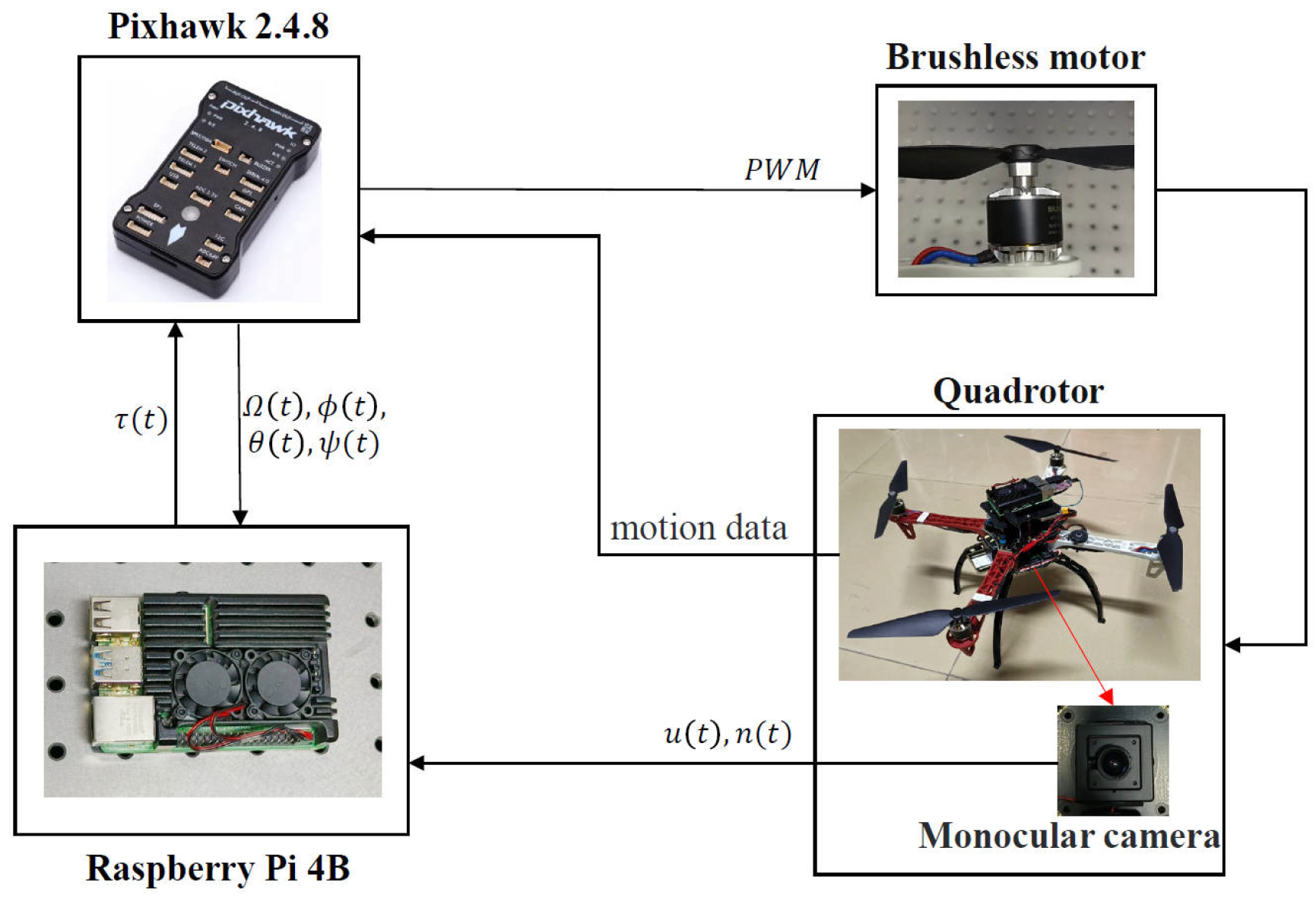
We use a quadrotor UAV from the Cangqiong Quadrotor Company in Chengdu, Sichuan Province, China to build the experimental platform, with its basic physical parameters listed in Table 1. To achieve precise control of the quadrotor UAV, the onboard system includes a Pixhawk 2.4.8 flight controller, a Raspberry Pi 4B onboard computer, a 2-megapixel monocular camera, and an M8N GPS module, all of which are provided by Cangqiong Quadrotor Company.
The Pixhawk flight controller features a 32-bit STM32F427 Cortex-M4 microcontroller, 2 MB flash memory, 256 KB RAM, and a 4 GB SD card. Additionally, it integrates a 3-axis 16-bit gyroscope (L3GD20) and a 3-axis 14-bit accelerometer/magnetometer for measuring attitude angles and angular velocities of the UAV.
The monocular camera is a USB plug-and-play model, fixed vertically downward at the bottom of the quadrotor. It can transmit high-definition video streams back to the Raspberry Pi. The Raspberry Pi 4B onboard computer is equipped with a 64-bit 1.5 GHz quad-core CPU, a 500 MHz VideoCore VI GPU, 4 GB DDR4 RAM, and supports Bluetooth 5.0, 802.11 ac (2.4/5 GHz) wireless networking as well as Gigabit Ethernet. It runs the Ubuntu 20.04 open-source operating system and features a WI-FI self-built hotspot (ACopter) function, allowing for a direct connection from a PC to form a local area network. Users can then remotely access the Raspberry Pi via SSH commands to write DroneKit-Python programs without requiring router configuration.
The control logic is illustrated in Figure 3. The Raspberry Pi communicates with the Pixhawk flight controller via the MAVLink protocol, accessing real-time flight parameters, such as attitude angles, angular velocities, and other state information. Simultaneously, it receives image data from the monocular camera via a USB connection and processes the images using OpenCV for feature extraction. Based on this information, the DroneKit program implements control algorithms to calculate the required moments around each axis for flight control and then sends these commands to the Pixhawk via MAVLink. The Pixhawk converts the control signals into PWM signals to drive the four brushless motors, achieving direct flight control.
Four markers serve as the visual feature targets, as shown in Figure 4. Based on their color and shape information, the centroids of the four markers are extracted [32]. After a rotational transformation, the coordinates of the four features on the virtual image plane can be obtained.

5.2. Performance Results

Under the hardware system described in the previous subsection, we primarily discuss the specific implementation of the proposed adaptive control algorithm. In all tests, the control inputs are calculated using the controllers in (32), (38) and (43), which yield the lift force U 1 and the desired angular velocity Ω d . Subsequently, the torque controller in (53) generates the moments acting on the body-frame axes of the quadrotor, thereby controlling the angular velocities Ω 1 , Ω 2 and Ω 3 . The observer and control parameters selected for the test are as follows: c 1 = 2 , k 1 = 5 , k 2 = 1 , k 3 = 1 , σ = 0.1 , r = 0.01 , the camera focal length λ = 3.2 mm , and the camera pixels are square with a length of 1.4 × 10 3 mm . Gravity acceleration g = 9.81 m/s2 is considered to be constant.
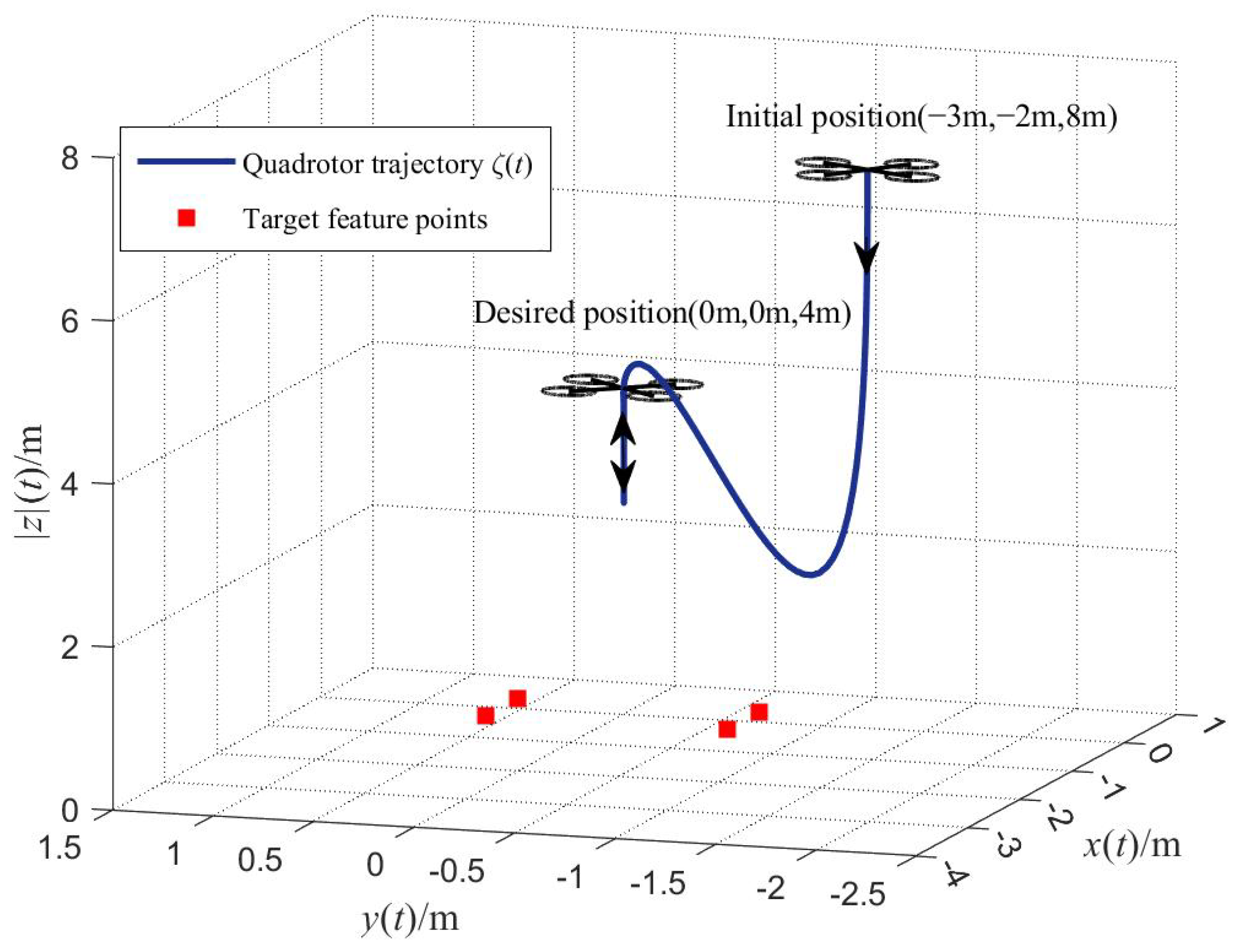
The servo targets in the experiment are four feature points on a horizontal plane, forming a rectangle. The coordinates of these four points relative to the inertial frame are ( 0.3 , 0.6 , 0 ) , ( 0.3 , 0.6 , 0 ) , ( 0.3 , 0.6 , 0 ) , and ( 0.3 , 0.6 , 0 ) m . The initial position of the vehicle in Cartesian space is ( 3 , 2 , 8 ) T m , and its initial Euler angles are 0, 0, and 0.174 rad, corresponding to the roll, pitch, and yaw angles, respectively. The initial estimated value of the moment of inertia vector J ^ v ( t 0 ) is ( 0.01 , 0.01 , 0.016 , 0 , 0 , 0 ) T , and the initial estimated mass of the quadrotor m ^ ( t 0 ) is 0. The desired image features are selected as q x d q y d q z d q ψ d T = ( 0 0 1 0 ) T , with a = 1.152 × 10 6 . The desired image features establish the target coordinates of the quadrotor as ( 0 , 0 , 4 ) T m , while all Euler angles should be zero. The test results are shown in Figure 5, Figure 6, Figure 7 and Figure 8.
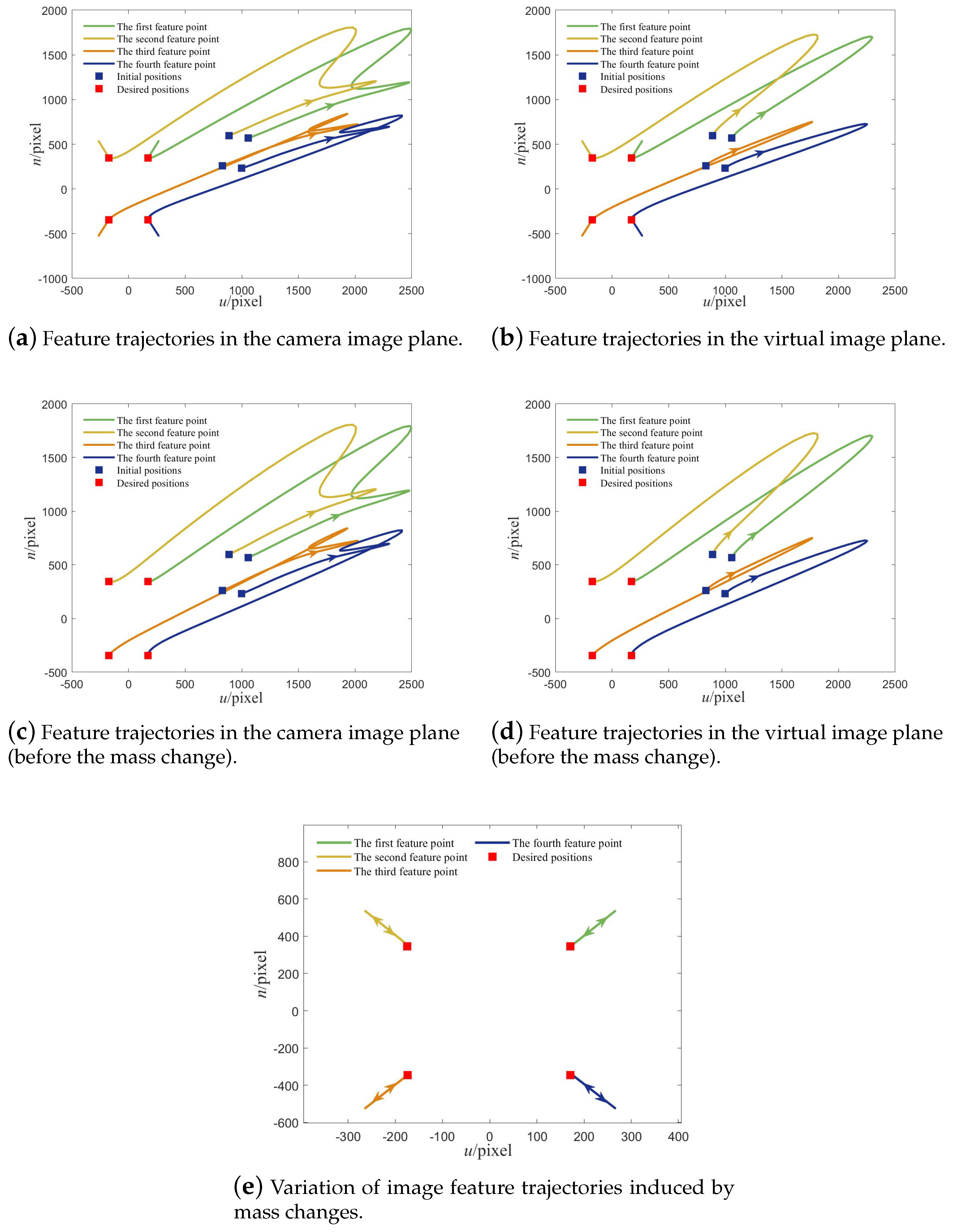
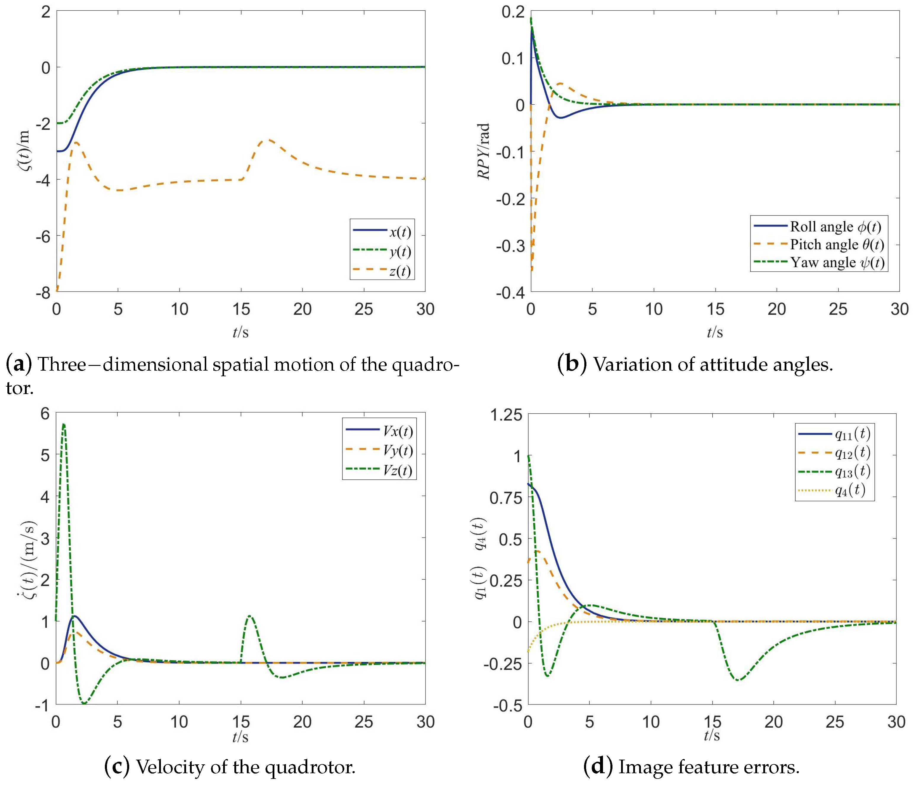
Due to the underactuated dynamic characteristics of the quadrotor, the vehicle must pitch or roll to generate horizontal translational motion. As shown in Figure 5 and Figure 6, after introducing the virtual camera, both the point features in the image plane and the flight trajectory of the quadrotor in 3D Cartesian space exhibit excellent smoothness. Additionally, this verifies the characteristics described in (11): on the virtual image plane, the behavior of feature points is not directly affected by the roll and pitch motions, thereby resulting in improved flight efficiency. From Figure 7, the XYZ axes represent the corresponding coordinate axes in the inertial frame. It can be observed that the UAV successfully achieves the desired goals in both position and attitude, with the image feature error dynamics achieving asymptotic stability. This demonstrates that the IBVS method proposed in this study exhibits strong stability and accuracy in both spatial motion control and attitude adjustment.
During the test, the mass of the drone is increased at 15 s. Based on Figure 5 and Figure 7, the three-dimensional space motion of the quadrotor stabilized in the desired position before 15 s. After the mass of the quadrotor is changed, the original lift of the UAV is not enough to support the new mass, and the altitude of the quadrotor decreases in the vertical direction and the velocity direction is downward. The image feature error q 13 is less than zero, and it can be seen from (12) and (17), which show that the value of a is less than a , i.e., the altitude is lower than the expected altitude. However, the controller makes adjustments in time, increases the control input, thereby increasing the total lift. After the UAV drops a certain height, it turns upward and the height gradually increases. Correspondingly, q 13 gradually approaches zero, and the velocity of the quadrotor shows a downward velocity, gradually decreases to zero, and then the speed direction turns upward. Until the desired height is reached, the velocity is zero, and the image errors return to zero. During this process, the controller shows good stability and robustness.
The changes in the image plane are illustrated in Figure 6. Prior to the test time of 15 s, the image feature points can gradually converge to their desired positions. After 15 s, due to the increase in the mass and the decrease in altitude, the monocular camera is closer to the feature points, and these feature points on the image plane expand outward. When the quadrotor descends to a certain altitude and then rises, these feature points in the image plane shrink to the desired positions. When the quadrotor returns to the desired altitude, the feature points reach the desired coordinates. Since the vehicle only moves in the vertical direction, the feature points change in the actual camera plane and the virtual camera plane in the same way.
The estimation results of the unknown mass and moment of inertia is shown in Figure 8. Both estimates stabilize at a certain constant value. Particularly, Figure 8 demonstrates that the estimation process for the moment of inertia converges very quickly. This enables rapid responses to internal and external state changes, allowing timely adjustments to the torque controller.
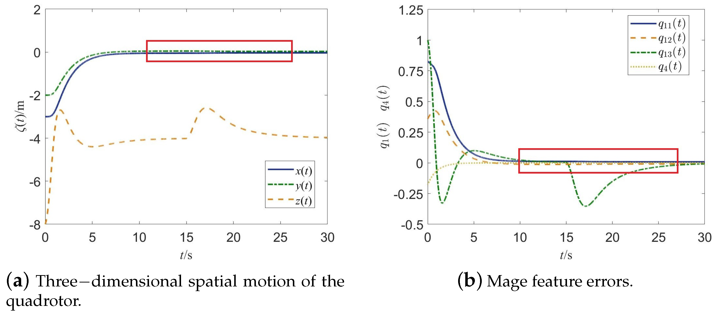
In order to better demonstrate the performance of the proposed control scheme, we also conducted experiments using a PID control scheme. The PID controller primarily replaced the torque controller for comparison. The selected proportional, integral, and derivative gains are 1, 0.5, and 0.1, respectively, and the results are shown in Figure 9. As can be observed from the red box in the figure, the positions on the x-axis and y-axis do not converge well, and there is always some deviation in the value of q 12 . Thus, it can be inferred that our control scheme exhibits good accuracy.

6. Conclusions

This study develops an adaptive vision-based control framework for a quadrotor equipped with a monocular camera to address the challenge of unknown dynamic parameters. By properly defining image moment features on the virtual image plane, the underactuation problem of the quadrotor is effectively handled without requiring time-varying depth values for each feature point. To ensure that the control system can adapt to the dynamic characteristics of the quadrotor, a torque controller is designed using the backstepping method. An adaptive estimation method is introduced to online estimate the unknown mass and moment of inertia. The stability of the system is proven mathematically, and numerical tests validate the controller’s efficacy and robustness under various operating conditions. Experimental results verify the UAV’s generation of continuous and efficient movement paths in both the imaging projection plane and Cartesian coordinate system.
It should be pointed out that the design or choice of adaptive laws mainly aims to ensure that the image error q 1 ( t ) defined in (17) converges to zero asymptotically, instead of converging the adaptive parameter estimates to true values. In most cases, how to ensure the latter is a sophisticated problem, and the establishment of its solution generally involves some stringent conditions, such as the persistency of excitation (PE) condition. As an extension of this work, we will focus on this problem, and we will aim to find its solutions in our future study.

Author Contributions

Conceptualization, Y.C.; Methodology, J.G.; Software, B.H.; Validation, B.H.; Data curation, G.Y.; Writing—original draft, J.G.; Writing—review & editing, G.L. All authors have read and agreed to the published version of the manuscript.

Funding

This work is supported by Guangdong Provincial Department of Education (Key Special Projects) Project (No. 2023ZDZX1086), supported by Special fund for Dongguan’s Rural Revitalization Strategy (No. 20211800400102), Also supported by Guangdong Provincial Philosophy and Social Science Planning Project (NO. GD25CSH06), Also supported by Dongguan Songshan Lake Enterprise Special Envoy Project (NO. 20234384-01KCJ-G and NO. 20234369-01KCJ-G).

Data Availability Statement

Data are contained within the article.

Conflicts of Interest

The funders had no role in the design of the study; in the collection, analyses, or interpretation of data; in the writing of the manuscript; or in the decision to publish the results.

References

  1. Wang, S.; Chen, J.; He, X. An adaptive composite disturbance rejection for attitude control of the agricultural quadrotor UAV. ISA Trans. 2022, 129, 564–579. [Google Scholar] [CrossRef] [PubMed]
  2. Lal, R.; Prabhakar, P. Time-Optimal Multi-Quadrotor Trajectory Planning for Pesticide Spraying. In Proceedings of the 2021 IEEE International Conference on Robotics and Automation (ICRA), Xi’an, China, 30 May–5 June 2021; pp. 7965–7971. [Google Scholar]
  3. Chen, G.; Peng, P.; Zhang, P.; Dong, W. Risk-Aware Trajectory Sampling for Quadrotor Obstacle Avoidance in Dynamic Environments. IEEE Trans. Ind. Electron. 2023, 70, 12606–12615. [Google Scholar] [CrossRef]
  4. Ben Abdi, S.; Debilou, A.; Guettal, L.; Guergazi, A. Robust trajectory tracking control of a quadrotor under external disturbances and dynamic parameter uncertainties using a hybrid P-PID controller tuned with ant colony optimization. Aerosp. Sci. Technol. 2025, 160, 110053. [Google Scholar] [CrossRef]
  5. Qin, C.; Yu, Q.; Go, H.S.H.; Liu, H.H.T. Perception-Aware Image-Based Visual Servoing of Aggressive Quadrotor UAVs. IEEE/ASME Trans. Mechatron. 2023, 28, 2020–2028. [Google Scholar] [CrossRef]
  6. Guenard, N.; Hamel, T.; Mahony, R. A Practical Visual Servo Control for an Unmanned Aerial Vehicle. IEEE Trans. Robot. 2008, 24, 331–340. [Google Scholar] [CrossRef]
  7. Zheng, D. Image-based Visual Serving of a Quadrotor UAV. Master’s Thesis, Shanghai Jiaotong University, Shanghai, China, 2018. [Google Scholar]
  8. Jiang, D.; Li, G.; Sun, Y.; Hu, J.; Yun, J.; Liu, Y. Manipulator grabbing position detection with information fusion of color image and depth image using deep learning. J. Ambient. Intell. Humaniz. Comput. 2021, 12, 10809–10822. [Google Scholar] [CrossRef]
  9. Miao, Z.; Zhong, H.; Wang, Y.; Zhang, H.; Tan, H.; Fierro, R. Low-Complexity Leader-Following Formation Control of Mobile Robots Using Only FOV-Constrained Visual Feedback. IEEE Trans. Ind. Inform. 2022, 18, 4665–4673. [Google Scholar] [CrossRef]
  10. Hamel, T.; Mahony, R. Visual servoing of an under-actuated dynamic rigid-body system: An image-based approach. IEEE Trans. Robot. Autom. 2002, 18, 187–198. [Google Scholar] [CrossRef]
  11. Bourquardez, O.; Mahony, R.; Guenard, N.; Chaumette, F.; Hamel, T.; Eck, L. Image-Based Visual Servo Control of the Translation Kinematics of a Quadrotor Aerial Vehicle. IEEE Trans. Robot. 2009, 25, 743–749. [Google Scholar] [CrossRef]
  12. Jabbari, H.; Oriolo, G.; Bolandi, H. Dynamic IBVS control of an underactuated UAV. In Proceedings of the 2012 IEEE International Conference on Robotics and Biomimetics (ROBIO), Guangzhou, China, 11–14 December 2012; pp. 1158–1163. [Google Scholar]
  13. Jabbari, H.; Oriolo, G.; Bolandi, H. An adaptive scheme for image-based visual servoing of an underactuated UAV. Int. J. Robot. Autom. 2014, 29, 92–104. [Google Scholar] [CrossRef]
  14. Zheng, D.; Wang, H.; Wang, J.; Chen, S.; Chen, W.; Liang, X. Image-Based Visual Servoing of a Quadrotor Using Virtual Camera Approach. IEEE/ASME Trans. Mechatron. 2017, 22, 972–982. [Google Scholar] [CrossRef]
  15. Sönmez, S.; Rutherford, M.J.; Valavanis, K.P. A Survey of Offline- and Online-Learning-Based Algorithms for Multirotor Uavs. Drones 2024, 8, 116. [Google Scholar] [CrossRef]
  16. Lei, W.; Li, C.; Chen, M.Z.Q. Robust Adaptive Tracking Control for Quadrotors by Combining PI and Self-Tuning Regulator. IEEE Trans. Control Syst. Technol. 2019, 27, 2663–2671. [Google Scholar] [CrossRef]
  17. Tang, M.; Lau, V.K.N. Online Identification and Temperature Tracking Control for Furnace System with a Single Slab and a Single Heater Over the Wirelessly Connected IoT Controller. IEEE Internet Things J. 2024, 11, 6730–6747. [Google Scholar] [CrossRef]
  18. Eschmann, J.; Albani, D.; Loianno, G. Data-Driven System Identification of Quadrotors Subject to Motor Delays. In Proceedings of the 2024 IEEE/RSJ International Conference on Intelligent Robots and Systems (IROS), Abu Dhabi, United Arab Emirates, 14–18 October 2024; pp. 8095–8102. [Google Scholar]
  19. Böhm, C.; Brommer, C.; Hardt-Stremayr, A.; Weiss, S. Combined System Identification and State Estimation for a Quadrotor UAV. In Proceedings of the 2021 IEEE International Conference on Robotics and Automation (ICRA), Xi’an, China, 30 May–5 June 2021; pp. 585–591. [Google Scholar]
  20. Noormohammadi-Asl, A.; Esrafilian, O.; Ahangar Arzati, M.; Taghirad, H.D. System identification and H∞-based control of quadrotor attitude. Mech. Syst. Signal Process. 2020, 135, 106358. [Google Scholar] [CrossRef]
  21. Zou, Y.; Meng, Z. Immersion and Invariance-Based Adaptive Controller for Quadrotor Systems. IEEE Trans. Syst. Man. Cybern. Syst. 2019, 49, 2288–2297. [Google Scholar] [CrossRef]
  22. Liu, Y.C.; Ou, T.W. Non-linear adaptive tracking control for quadrotor aerial robots under uncertain dynamics. IET Control Theory Appl. 2021, 15, 1126–1139. [Google Scholar] [CrossRef]
  23. Liang, W.; Chen, Z.; Yao, B. Geometric Adaptive Robust Hierarchical Control for Quadrotors with Aerodynamic Damping and Complete Inertia Compensation. IEEE Trans. Ind. Electron. 2022, 69, 13213–13224. [Google Scholar] [CrossRef]
  24. Xie, H.; Lynch, A.F.; Low, K.H.; Mao, S. Adaptive Output-Feedback Image-Based Visual Servoing for Quadrotor Unmanned Aerial Vehicles. IEEE Trans. Control Syst. Technol. 2020, 28, 1034–1041. [Google Scholar] [CrossRef]
  25. Imran, I.H.; Wood, K.; Montazeri, A. Adaptive Control of Unmanned Aerial Vehicles with Varying Payload and Full Parametric Uncertainties. Electronics 2024, 13, 347. [Google Scholar] [CrossRef]
  26. Lin, J.; Miao, Z.; Wang, Y.; Hu, G.; Wang, X.; Wang, H. Error-State LQR Geofencing Tracking Control for Underactuated Quadrotor Systems. IEEE/ASME Trans. Mechatron. 2024, 29, 1146–1157. [Google Scholar] [CrossRef]
  27. Zhou, L.; Zhang, J.; Dou, J.; Wen, B. A fuzzy adaptive backstepping control based on mass observer for trajectory tracking of a quadrotor UAV. Int. J. Adapt. Control Signal Process. 2018, 32, 1675–1693. [Google Scholar] [CrossRef]
  28. Bouabdallah, S. Design and Control of Quadrotors with Application to Autonomous Flying. Ph.D. Thesis, EPFL, Lausanne, Switzerland, 2007. [Google Scholar]
  29. Chaumette, F. Image moments: A general and useful set of features for visual servoing. IEEE Trans. Robot. 2004, 20, 713–723. [Google Scholar] [CrossRef]
  30. Lu, M.; Chen, H.; Lu, P. Perception and Avoidance of Multiple Small Fast Moving Objects for Quadrotors with Only Low-Cost RGBD Camera. IEEE Robot. Autom. Lett. 2022, 7, 11657–11664. [Google Scholar] [CrossRef]
  31. Lopez-Sanchez, I.; Montoya-Cháirez, J.; Pérez-Alcocer, R.; Moreno-Valenzuela, J. Experimental Parameter Identifications of a Quadrotor by Using an Optimized Trajectory. IEEE Access 2020, 8, 167355–167370. [Google Scholar] [CrossRef]
  32. Yao, Z.; Yi, W. Curvature aided Hough transform for circle detection. Expert Syst. Appl. 2016, 51, 26–33. [Google Scholar] [CrossRef]
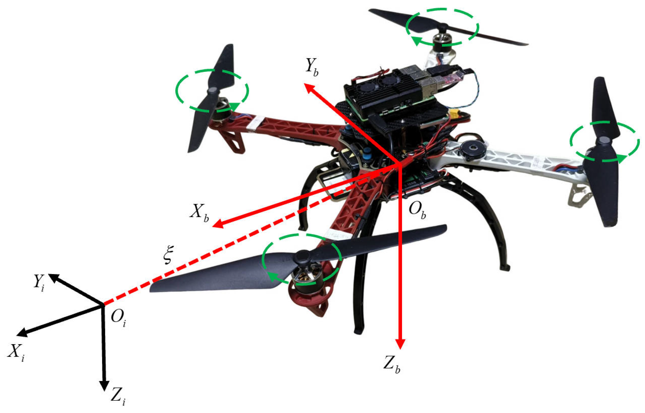
Figure 1. Inertial frame and quadrotor body frame.
Electronics 14 03114 g001
Figure 2. A block diagram of the proposed adaptive control scheme.
Electronics 14 03114 g002
Figure 3. Quadrotor signal control diagram.
Electronics 14 03114 g003
Figure 4. The actual operation process of the quadrotor system.
Electronics 14 03114 g004
Figure 5. Quadrotor space trajectory.
Electronics 14 03114 g005
Figure 6. Feature trajectories in the virtual image plane and camera image plane.
Electronics 14 03114 g006
Figure 7. Time evolution of quadrotor state variables and visual feature errors.
Electronics 14 03114 g007
Figure 8. Time evolution of adaptive estimation for unknown parameters.
Electronics 14 03114 g008
Figure 9. Time evolution of 3D spatial motion and image feature errors using the PID scheme.
Electronics 14 03114 g009
Table 1. Basic physical parameters of quadcopter UAV.
ParameterValueUnits
Wheelbase450mm
Empty weight1.493kg
Loadable capacity0.5kg
Motor diameter22mm
Camera resolution1920 × 1080pixel
Disclaimer/Publisher’s Note: The statements, opinions and data contained in all publications are solely those of the individual author(s) and contributor(s) and not of MDPI and/or the editor(s). MDPI and/or the editor(s) disclaim responsibility for any injury to people or property resulting from any ideas, methods, instructions or products referred to in the content.