Review

Grain Boundary Engineering for High-Mobility Organic Semiconductors

1
Electrical and Computer Engineering, Pennsylvania State University at Erie, Erie, PA 16563, USA
2
Key Laboratory for Precision and Non-Traditional Machining Technology of the Ministry of Education, Dalian University of Technology, Dalian 116024, China
*
Authors to whom correspondence should be addressed.
Electronics 2025, 14(15), 3042; https://doi.org/10.3390/electronics14153042 (registering DOI)
Submission received: 13 June 2025 / Revised: 14 July 2025 / Accepted: 22 July 2025 / Published: 30 July 2025
(This article belongs to the Special Issue Feature Papers in Electronic Materials)

Abstract

Grain boundaries are among the most influential structural features that control the charge transport in polycrystalline organic semiconductors. Acting as both charge trapping sites and electrostatic barriers, they disrupt molecular packing and introduce energetic disorder, thereby limiting carrier mobility, increasing threshold voltage, and degrading the stability of organic thin-film transistors (OTFTs). This review presents a detailed discussion of grain boundary formation, their impact on charge transport, and experimental strategies for engineering their structure and distribution across several high-mobility small-molecule semiconductors, including pentacene, TIPS pentacene, diF-TES-ADT, and rubrene. We explore grain boundary engineering approaches through solvent design, polymer additives, and external alignment methods that modulate crystallization dynamics and domain morphology. Then various case studies are discussed to demonstrate that optimized processing can yield larger, well-aligned grains with reduced boundary effects, leading to great mobility enhancements and improved device stability. By offering insights from structural characterization, device physics, and materials processing, this review outlines key directions for grain boundary control, which is essential for advancing the performance and stability of organic electronic devices.

1. Background and Introduction

In organic semiconductors, charge transport is not solely determined by molecular order or packing density [1,2,3,4,5,6,7,8], but is equally shaped by the underlying energetic landscape described by the density of states (DOS) [9,10,11,12,13,14,15]. While delocalized states in highly ordered crystalline systems support coherent band-like transport, structural imperfections and energetic disorder introduce localized states, which are commonly referred to as trap states within the band gap [16,17,18,19,20]. Among these imperfections, grain boundaries are especially critical as they often serve as sites for trap localization [21,22,23]. These localized states impact carrier mobility by temporarily capturing charges, thereby disrupting the flow of current [24,25,26]. Depending on their energetic position relative to the band edges, traps may be shallow, which still allows carriers to be thermally released, or traps may be deep, where recombination and permanent carrier loss become significant [27,28,29]. In addition to intrinsic disorder, the incorporation of guest molecules into the host matrix can further modulate trap behavior by introducing additional trap or anti-trap states [30,31,32]. As a result, understanding the formation and distribution of traps and particularly at grain boundaries becomes essential for interpreting the charge transport behavior in polycrystalline and amorphous organic semiconductors.

1.1. Grain Boundaries as Charge Carrier Traps

Here we begin by examining four representative DOS models commonly used to describe different classes of organic semiconductors: crystalline systems with well-defined band edges, weakly disordered materials with exponential tail states, and highly disordered polycrystalline or amorphous systems modeled using Gaussian or exponential distributions [33,34,35,36,37,38,39,40,41,42]. Beyond the DOS for extended states, localized trap states, which originate from structural imperfections, chemical impurities, or energetic disorder, also play a critical role in charge dynamics [43,44,45]. Shallow traps, located near the Highest Occupied Molecular Orbital (HOMO) or Lowest Unoccupied Molecular Orbital (LUMO) edges, can capture carriers temporarily and enable thermally assisted multiple-trap-and-release transport [46,47,48]. In contrast, deep traps act as recombination centers, which may reduce carrier lifetime and mobility [49,50,51,52]. Furthermore, depending on their relative energy levels, guest molecules incorporated into host lattices can introduce additional trap or anti-trap states, which can alter the transport behavior [32].
To illustrate how these states arise and influence charge conduction pathways in organic semiconductors, Figure 1a–d show four common types of DOS profiles used to describe the energetic distribution of electronic states in different classes of semiconductors. In Figure 1a, the DOS of a perfectly ordered crystalline semiconductor, such as crystalline silicon (c-Si), follows a parabolic distribution with sharply defined valence (EV) and conduction (EC) band edges, resulting in a well-defined energy gap. Figure 1b depicts a semiconductor with weak disorder, such as amorphous silicon (a-Si), where extended states gradually decay into the band gap and form exponential tail states. In such systems, the precise band edges are ill-defined, and a mobility edge is introduced to differentiate extended from localized states. Figure 1c shows the DOS in highly disordered semiconductors, including many polycrystalline organic semiconductors, where the DOS for the HOMO and LUMO levels resembles Gaussian functions. Here, the energy gap is defined between the onsets of the HOMO and LUMO tails. Finally, Figure 1d represents another model for disordered semiconductors, where the DOS decays exponentially from the HOMO and LUMO edges into the gap. These models highlight how structural disorder, molecular packing, and electronic localization determine the DOS shape, which in turn controls the charge transport behavior in the semiconductor systems.
Figure 1e illustrates the nature and transport implications of electronic traps in organic semiconductors. On the left, the trap DOS function shows the distribution of trap states within the band gap, with shallow traps (black) concentrated near the band edges and deep traps (red) located further away. These localized electronic states arise from imperfections in the semiconductor and are energetically distributed according to their depth from the conduction (LUMO) or valence (HOMO) band edges. Shallow traps, which are typically tail states, are situated within a few kT of the band edges and can often release trapped carriers back into the band via thermal activation, particularly in the multiple-trap-and-release process shown by the blue arrows. In contrast, deep traps, which are several kT away, act as recombination centers and are unlikely to thermally release carriers, reducing their mobility and lifetime. On the right, the spatial and energy diagram depicts transport mechanisms influenced by these traps: band-like transport occurs through delocalized states (black arrows), multiple trap and release involves transient trapping and release from shallow states (blue arrows), and hopping transport (orange arrows) occurs between localized states when trap density is high. This highlights how both the energetic depth and spatial distribution of traps fundamentally determine the dominant charge transport regime in organic semiconductors.
Figure 1f presents four hypothetical cases, shown from left to right, that illustrate how guest molecules incorporated into a host semiconductor lattice can generate trap or anti-trap states affecting charge transport. In the leftmost diagram, both electron and hole traps are introduced because the LUMO and HOMO levels of the guest fall within the energy gap of the host. This situation is exemplified by tetracene-doped anthracene crystals, where electron traps appear near the conduction band and hole traps appear near the valence band, leading to a decrease in mobility, especially for holes. In the second diagram, only hole traps are formed when the guest HOMO lies within the gap, as in the case of phenothiazine-doped anthracene, where a hole trap at 0.8 eV above the valence band was detected. The third diagram represents an energetically inert guest, whose ionization energy is higher and electron affinity is lower than those of the host, preventing the formation of traps. Though not directly associated with trapping, such guests still disturb the lattice locally and act as scattering centers, depending on their concentration. In the rightmost diagram, only electron traps are created by the guest molecule, with trap levels situated below the conduction band, as observed in anthracene doped with compounds like acridine and phenazine. Together, these cases show how the alignment of guest and host energy levels determines the trapping behavior and ultimately affects charge carrier mobility in organic semiconductors.

1.2. Grain Boundaries as Potential Barriers

Grain boundaries in organic semiconductors can also serve as electrostatic barriers that impede the movement of charge carriers by creating localized energetic obstacles [53,54,55]. These regions often trap carriers and generate a surrounding space-charge region, which repels other carriers of the same type. This leads to a built-in potential and local band bending, particularly downward in p-type semiconductors where holes are trapped [56]. The resulting energy barrier, often referred to as the barrier height, determines how easily carriers can move across the boundary [57,58]. Thermal activation enables carriers to overcome this barrier, while tunneling may become significant at lower temperatures.
Horowitz et al. explore the influence of grain boundaries on charge carrier mobility in polycrystalline organic thin-film transistors (OTFTs) made with vacuum-deposited oligothiophenes [59]. Their study reveals that grain boundaries serve as key sites for trap localization, which in turn act as energy barriers to carrier transport. Mobility in these polycrystalline films increases with grain size. In particular, small grains exhibit thermally activated mobility consistent with the presence of barriers at grain boundaries, while larger grains demonstrate temperature-independent mobility at low temperatures, suggesting a transition to tunneling-dominated transport across grain boundaries. The authors propose a model in which traps are not uniformly distributed throughout the film but are concentrated at grain boundaries. These boundaries create potential barriers that carriers must overcome either by thermal activation (dominant at high temperatures) or by quantum tunneling (dominant at low temperatures). The barrier height depends on the grain size relative to the Debye length, with larger grains resulting in more significant barrier effects. Experimental results from this study, including scanning electron microscopy and temperature-dependent mobility measurements, support this model and show a near-linear relationship between mobility and grain size.
Verlaak et al. presented a detailed model explaining how grain boundaries influence charge transport in polycrystalline organic semiconductor films, particularly in pentacene-based thin-film transistors [60]. The authors propose a grain boundary barrier model in which an energy distribution of interfacial trap states rather than a single trap level is responsible for charge trapping at grain boundaries. These trapped charges, located in the amorphous regions between crystalline grains, repel mobile charges of the same sign and lead to the formation of a space-charge region (SCR). The SCR generates a potential barrier that charge carriers must overcome via thermionic emission, which limits mobility. The model shows that the barrier height is influenced by both the density of trapped charges at the grain boundaries and the doping concentration in the grains. Higher doping results in better screening of trapped charges, thus reducing the SCR width and lowering the barrier, which enhances mobility. Unlike other models (e.g., multiple-trap-and-release or potential well models), this approach distinguishes itself by predicting that mobility is more strongly affected by dopant concentration than by gate voltage, due to the differing screening mechanisms involved. This behavior aligns with experimental observations where unintentionally doped films showed higher mobilities compared to purified ones with similar morphologies. Additionally, the model explains channel-length-dependent mobility, where shorter channels show higher mobility due to fewer grain boundaries and stronger local electric fields that lower the potential barrier. Overall, the findings underscore that grain boundaries are not just structural interruptions but electrostatic barriers shaped by trap distributions and doping, and they play a pivotal role in determining the transport properties of polycrystalline organic semiconductors.

1.3. Grain Width-Dependent Model

Controlling the grain width and grain boundary dimension of organic semiconductors is important in minimizing defects and deformities at crystalline grain boundaries. These defects and deformities can act as trap centers of charge, which adversely affect charge carrier transport. By increasing the grain size, there are fewer boundaries and defects, which expedites the transport of charge carriers. One way to assess the impact of grain boundary defects and deformities on organic semiconductor charge transport is through the “grain width-dependent mobility model” [61]. For instance, the channel can be expressed as having a length of L.
L = n L G + ( n 1 ) L G B
The crystal length, L G , and grain boundary length, L G B , along with the number of grain boundaries, n, are used to calculate the total effective mobility, μ E . It is important to note that L G B has a small dimension of 1–2 nm and is connected in series. When L is much larger than L G B , the expression for μ E can be derived.
L μ E = L ( n 1 ) L G B μ G + ( n 1 ) L G B μ G B
The mobility of crystal grains and grain boundary are represented by μ G and μ G B , respectively. Combining Equations (1) and (2) results in the following expression:
1 μ E = 1 μ G + n ( L G B L μ G B L G B L μ G )
Given the enormous magnitude of n, the equation above approximates (n − 1) to n. There exists a correlation between the width of the grain, W G , and its length, L G .
sin θ = W G L G = n W G L
n = L s i n θ W G
Since A = 1 μ G and B = s i n θ L G B ( 1 μ G B 1 μ G ) , Equation (5) can be merged into (3):
1 μ E = A + B W G
The mobility model described in Equation (6) is known as the “grain width-dependent model”. It states that the effective total mobility μ E increases proportionally with an increase in grain width. This means that a fixed channel with a larger grain width will have a higher effective mobility. To reduce the amount of crystalline defects and trap centers, it is preferable to have crystals with larger grain width given a fixed channel dimension. The dimension of organic crystal grains and organic semiconductor crystallization can be affected by several factors, including solvent choice, polymer additive, and external alignment and patterning.
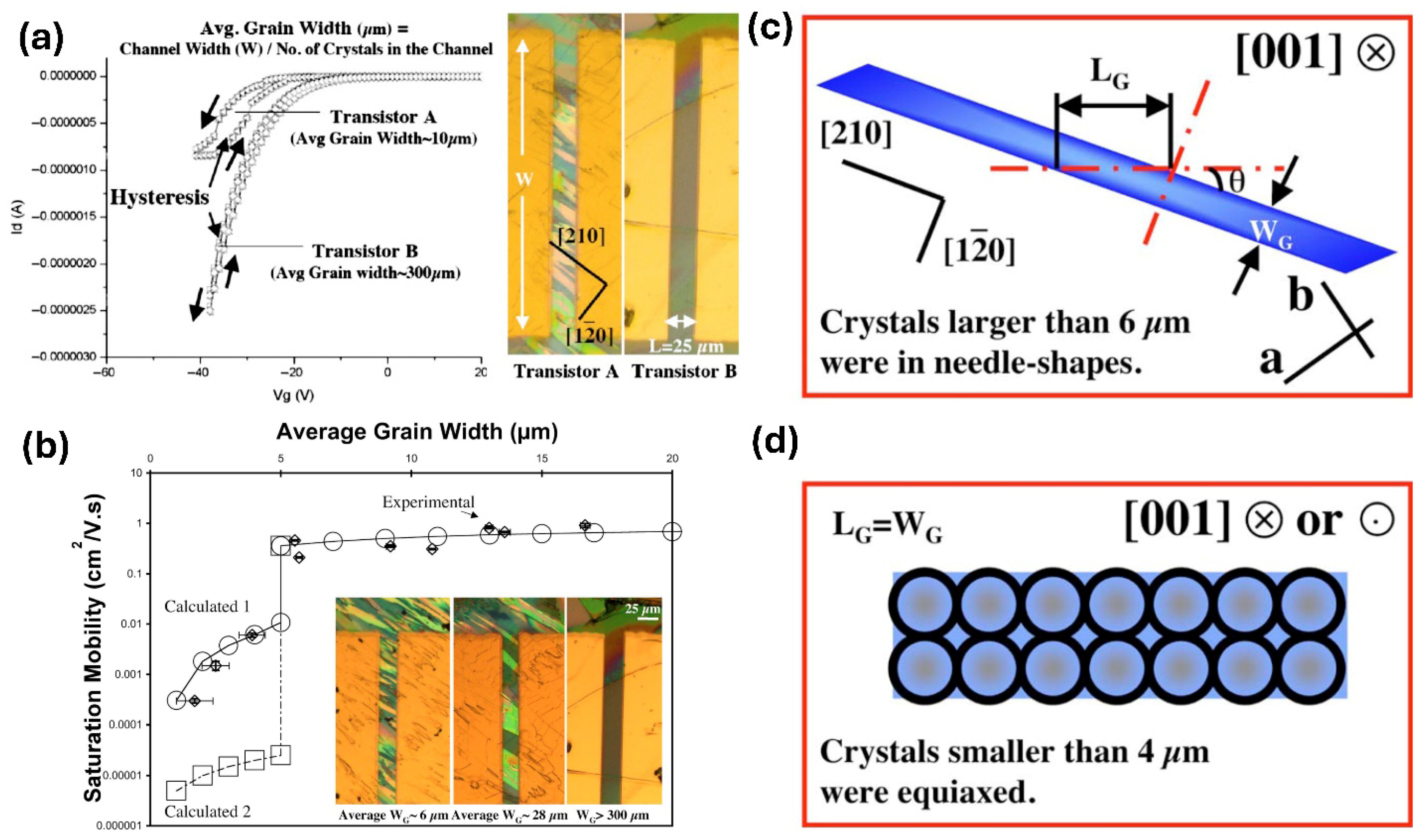
Figure 2 further supports this model by directly visualizing the relationship between grain width and device performance in solution-processed 6,13-bis(triisopropylsilylethynyl)pentacene (TIPS pentacene) transistors. In Figure 2a, transfer characteristics of two devices reveal that the one with narrower grains (10 μm) exhibits more pronounced hysteresis and lower drain current, while the device with wider grains (300 μm) demonstrates enhanced current output and reduced hysteresis, highlighting the detrimental effect of frequent grain boundaries on charge transport. Figure 2b plots saturation mobility as a function of average grain width, showing a sharp increase in mobility beyond 6 μm, where the grain morphology transitions from equiaxed domains to elongated needle-like crystals. This morphological transition is illustrated in Figure 2c,d: needle-shaped grains are characterized by a long grain length LG and narrower width WG, oriented primarily along the axis, which minimizes the number of grain boundaries encountered along the transport path; in contrast, equiaxed grains, observed when WG < 4 μm, lead to frequent grain boundary interruptions. Together, they demonstrate that promoting anisotropic, aligned grain growth is key to suppressing boundary-induced scattering and achieving higher mobility, in agreement with the grain width-dependent model.

1.4. Impact of Grain Boundary on Electrical Performance of OTFTs

Grain boundaries have a fundamental impact on charge transport in organic semiconductors by disrupting molecular packing and introducing localized trap states and energetic barriers [62,63,64,65,66]. In single-crystalline organic semiconductors, where conjugated molecules are tightly and uniformly arranged, carriers can move coherently through delocalized states, exhibiting band-like transport [67,68,69,70]. However, in polycrystalline films, the presence of grain boundaries interrupts these transport pathways, leading to carrier localization [71,72,73]. As a result, the transport mechanism transitions from band-like to thermally activated modes such as hopping or multiple trap and release, especially at higher temperatures where thermal energy assists carriers in overcoming the barriers posed by grain boundaries. This transition is reflected in the temperature dependence of mobility: while ideal band-like systems show decreasing mobility upon cooling, polycrystalline films with high grain boundary density often show the opposite trend. Moreover, grain boundaries can distort Hall effect measurements, suppressing Hall mobility relative to field-effect mobility due to their influence on free carrier distribution and motion [74,75,76,77]. Therefore, the density, orientation, and distribution of grain boundaries, which are largely determined by processing conditions, are key factors in defining whether charge transport in an organic semiconductor remains coherent or becomes trap-limited.
In addition to influencing charge transport, grain boundaries also degrade the electrical performance of OTFTs [78,79,80,81]. Grain boundaries serve as sites for charge trapping and potential barriers, which reduce mobility and shift the threshold voltage by requiring a higher gate voltage to induce a conductive channel. These trapped charges can elevate the off-state current, decreasing the on/off current ratio, which is an important figure of merit in transistor operation. Moreover, grain boundaries introduce charge instability that results in hysteresis between forward and reverse gate voltage sweeps, reflecting delayed charge responses and reduced switching reliability [82,83,84,85,86]. The negative impact of grain boundaries is most pronounced in the early layers of OSC films, where carriers are forced to move laterally through high-resistance boundaries. However, increasing the film thickness can allow vertical transport pathways that partially bypass the grain boundaries. Overall, grain boundaries compromise key performance indicators such as mobility, threshold voltage, current on/off ratio, and switching uniformity, making their control essential for high-performance organic transistor design.
Grain boundaries also pose a big challenge to the long-term stability of OTFTs, particularly in terms of operational and environmental robustness [87,88,89,90]. Under prolonged gate bias, grain boundaries act as preferential sites for charge trapping, leading to gradual shifts in threshold voltage, reduced mobility, increased subthreshold slope, and intensified hysteresis. These instability effects are amplified in devices with high grain boundary density, where more trapping sites accelerate performance degradation over time. In addition to operational instability, grain boundaries are highly sensitive to environmental conditions [91,92,93]. Exposure to ambient air allows oxygen and water molecules to infiltrate grain boundary regions, where they introduce additional trap states or interact with the OSC lattice, distorting its structure. These environmental interactions reduce mobility and alter threshold voltage, which undermines the storage stability of the devices. In contrast, single-crystal OTFTs, which lack grain boundaries, maintain much more stable electrical performance during extended storage. The underlying mechanisms include both the diffusion of small molecules into grain boundaries and the thermally driven rearrangement of OSC molecules at boundary regions into less optimal configurations. Therefore, grain boundaries are not only obstacles to immediate device performance but also active sites that accelerate long-term degradation under bias and environmental exposure.
The introduction provides an overview of the important role grain boundaries play in determining charge transport behavior in organic semiconductors. It explains that charge mobility is governed not only by molecular order but also by DOS. Various DOS models are discussed, ranging from ordered crystalline to highly disordered systems, along with the energetic and spatial characteristics of shallow and deep traps. This section also illustrates how guest molecules can introduce or suppress traps, influencing mobility. Grain boundaries are further shown to function as electrostatic barriers due to space-charge regions formed by trapped carriers, with their impact dependent on grain size and doping levels. The grain width-dependent mobility model is introduced to describe how grain size correlates with mobility, supported by experimental data from TIPS pentacene transistors. Finally, the section emphasizes the detrimental impact of grain boundaries on the performance and stability of OTFTs, highlighting their influence on mobility, threshold voltage, hysteresis, and degradation under bias and environmental exposure. This sets the stage for the review’s focus on strategies to mitigate grain boundary effects and optimize organic electronic device performance. The goal of this review is to explore how grain boundary engineering strategies influence charge transport in polycrystalline organic semiconductors and to establish structure-specific guidelines for optimizing device performance. Rather than testing a singular hypothesis, this work addresses a central question: how can processing methods be tailored to control grain boundary structure and reduce trap-related transport limitations? By comparing the effectiveness of these approaches across representative high-mobility semiconductors, we aim to extract generalizable principles that can inform future material-specific optimization and the broader design of high-performance organic electronic devices.

2. Methods for Grain Boundary Engineering

Controlling the crystallization behavior of organic semiconductors is essential for optimizing film morphology, grain size, and device performance. Among the many strategies available, the use of solution-based methods provides a highly tunable platform for influencing crystallization during film formation. This section explores three key approaches, including solvent choice, polymer additives, and external alignment techniques, which have proven effective in modulating grain width and boundary characteristics. The term “engineering” refers to the intentional manipulation of processing conditions to control grain boundary structure and morphology in order to optimize charge transport in organic semiconductors. By tailoring solvent properties, incorporating specific polymers, or applying physical alignment strategies, researchers can achieve precise control over crystal growth and microstructure, thereby enhancing the uniformity and electronic properties of organic semiconductor films.

2.1. Solvent Choices

The selection of solvents plays a role in regulating the crystallization behavior of organic semiconductors, leading to variations in grain size and boundary dimensions [94,95,96,97]. Solvents with high boiling points promote longer crystal growth times for organic semiconductors than those with low boiling points. When grown in high-boiling-point solvents, organic semiconductors typically exhibit wider grain widths and reduced grain boundaries. Using binary solvents is particularly intriguing for effectively manipulating semiconductor crystallization and grain size [98,99,100,101,102]. In binary solvents, two different solvents are used, one being the primary solvent and the other an additive. The dissimilarity in molecular structure between the solvents and their affinity influence the intermolecular interactions, such as solute/solvent, solute/solute, and solvent/solvent interactions, which determine the intensity of the solution [103,104,105]. Choosing the appropriate binary solvents requires consideration of the dielectric constant, boiling point, and Hansen’s solubility parameters, among other factors of the solvents. A higher polarity of the solvent and improved ability to stabilize charges in the solvent are a result of a large dielectric constant. When two solvents have similar boiling points, they can maintain a simultaneous evaporation profile, which allows for easier control of the crystallization process of organic semiconductors. The binary solvent affinity and solubility are determined by Hansen’s solubility parameters, which consider the polar component, dispersive component, and hydrogen bonding component as the intermolecular interaction force [106,107,108]. The mismatch parameter R can be calculated using p , d , and h :
R = P 2 + d 2 + h 2
The smaller the mismatch parameter, as described in Equation (7), the better the solubility of a solute in a potential solvent with similar Hansen’s solubility parameters. On the other hand, low solubility is indicated by a large mismatch parameter.

2.2. Polymer Additives

Additives based on polymers, including amorphous, conjugated, and semicrystalline types, have been utilized to adjust the morphology, crystallization, alignment, and grain dimensions of organic semiconductors. This modulation enhances the device performance and charge carrier mobility of semiconductor devices. An interesting point to note is that these polymer additives can be used independently to regulate the semiconductor crystallization without any external alignment methods [109,110,111], which simplifies the experimental setup. In particular, amorphous polymers that enhance semiconductor morphology, decrease crystal misorientation and increase the size of grains have been reported, including poly(α-methylstyrene) (PαMS) [112,113,114,115], polystyrene (PS) [116,117,118,119,120,121], and poly(methylmethacrylate) (PMMA) [122,123,124,125,126,127,128]. Additionally, conjugated polymers such as poly(3-hexylthiophene) (P3HT) and regiorandom pentacene-bithiophene polymer (PnBT-RRa) [129,130,131,132,133,134,135,136,137,138] have similar effects to amorphous polymers in controlling semiconductor growth, morphology and grain size. Conjugated polymers facilitate intermolecular interactions with organic semiconductors, providing an extra way to reinforce π-π and hydrophobic interactions and manipulate morphological features. The resultant properties of the organic semiconductor/conjugated polymer mixed film can differ depending on several important material properties of the conjugated polymers, including their chemical structure, molecular weight, polydispersity, and regioregularity. Semicrystalline polymers, which possess properties from both amorphous and crystalline nature, provide a unique opportunity to fine-tune the crystallization and grain dimension of organic semiconductors.

2.3. External Alignment

In enhancing organic crystal growth in solution, morphology uniformity, and grain dimensions, external alignment and patterning methods are highly sought after. This has led to numerous studies, with various external alignment methods falling under the categories of substrate patterning [139,140,141,142], air flow [143,144], and blade coating [145,146,147,148]. In particular, substrate patterning-based methods utilize photolithography and/or surfactant treatment to alter substrate wettability, ultimately affecting solution dewetting behavior on the substrate. Crystallization in the deposited solution can be confined to wettable regions, allowing for easy tuning of the resulting grain dimension by controlling the wettability dimension. Techniques involving air or inert gas injection during the crystallization process of organic semiconductors can effectively modulate solute diffusion, improve crystal alignment, and enhance the long-range order of the semiconductors. These techniques can also reduce the coffee ring effect and tune the grain dimension. Blade coating, which uses a movable blade or substrate and a coating head, can control active layer thickness, morphology, contact resistance, and grain dimension by optimizing deposition speed, blade distance, and viscoelastic properties.
To summarize this section, grain boundary engineering in organic semiconductors can be effectively achieved through solvent optimization, polymer additive incorporation, and external alignment techniques. Each method offers unique advantages in tailoring crystal growth, improving grain orientation, and minimizing grain boundary density. Together, these strategies provide a useful way of controlling film morphology and enhancing charge transport properties, laying the foundation for high-performance organic electronic devices.

3. Case Studies of Grain Boundary Engineering

Grain boundaries represent one of the most significant bottlenecks in the performance of organic semiconductors, acting as both physical and energetic barriers to charge transport. This section presents a series of case studies that examine how grain boundary engineering has been employed across various benchmark small-molecule semiconductors, including pentacene, TIPS pentacene, diF-TES-ADT, and rubrene, with the goal of understanding and mitigating their detrimental effects. Through carefully designed experiments and advanced characterization techniques, these studies reveal how processing parameters such as deposition temperature, solvent system, polymer blending, and substrate treatment influence grain size, boundary density, alignment, and electrical properties. Collectively, they highlight that while grain boundaries can severely hinder charge mobility by introducing traps and increasing resistance, targeted engineering strategies, such as promoting large crystalline domains, reducing misorientation, or aligning grains, can enhance charge transport and device reliability.

3.1. Pentacene

Pentacene is a prototypical small-molecule organic semiconductor that has attracted extensive attention for its exceptional charge transport properties and well-defined molecular structure [149,150,151]. It consists of five linearly fused benzene rings, forming a highly conjugated planar backbone that facilitates strong intermolecular π-π stacking. Pentacene tends to form layered crystalline structures with anisotropic charge transport primarily along the molecular stacking direction. It is typically deposited via thermal evaporation, resulting in thin films with polycrystalline domains. Pentacene exhibits p-type semiconducting behavior with intrinsic hole mobilities often exceeding 1 cm2/Vs in optimized single-crystal devices [152,153,154,155]. These properties, combined with its relatively low fabrication cost and compatibility with large-area electronics, have made pentacene a benchmark material for thin-film transistors. However, despite its promising characteristics, pentacene thin films commonly exhibit polycrystalline morphologies, where the presence of grain boundaries introduces limitations [156,157,158,159,160,161,162]. These grain boundaries can act as energetic barriers and trap sites, which disrupt the continuity of charge transport pathways and lead to reduced mobility, increased contact resistance, and degraded device stability. Furthermore, the presence of structural disorder at these interfaces can enhance sensitivity to environmental factors such as moisture and oxygen. Understanding how grain boundaries influence the electrical behavior of pentacene is therefore important for improving the performance of organic electronic devices. In this section, we review several foundational studies that focus on the role of grain boundaries in pentacene and highlight their impact on charge carrier mobility, trap density, and environmental responsiveness, which provide insights into controlling crystallization and microstructure to mitigate grain boundary effects and unlocking the full potential of pentacene-based organic electronics.
Edura et al. explored how electrical transport differs across individual crystalline regions and the interfaces between them in pentacene films [163]. By combining electron beam and optical lithography, they fabricated microscale electrode layouts that enabled high-precision resistance and current measurements within isolated grain interiors and their adjoining boundaries. The active semiconductor layer was deposited using molecular beam epitaxy, yielding high-purity pentacene structures. Their findings revealed that current flow through a single crystal region was nearly ten times greater than across a boundary, with corresponding hole mobilities of 5 cm2/Vs within the grain and 0.3 cm2/Vs across the boundary. Resistance measurements further confirmed this disparity, estimating 10 MΩ for the grain and 100 MΩ at the grain interface. This study stands out for its direct and quantitative dissection of charge transport mechanisms within organic semiconductor microstructures. By separately characterizing intra-grain and inter-grain electrical properties, it provided some of the first clear experimental evidence quantifying the detrimental impact of grain boundaries on mobility. Moreover, the precise fabrication and measurement techniques demonstrated in this work offer a model approach for future studies on grain-level phenomena in organic thin-film devices. The large contrast in mobility and resistance highlights the critical role of microstructure in determining device performance, as well as the impact of engineering grain boundaries in high-performance organic electronics.
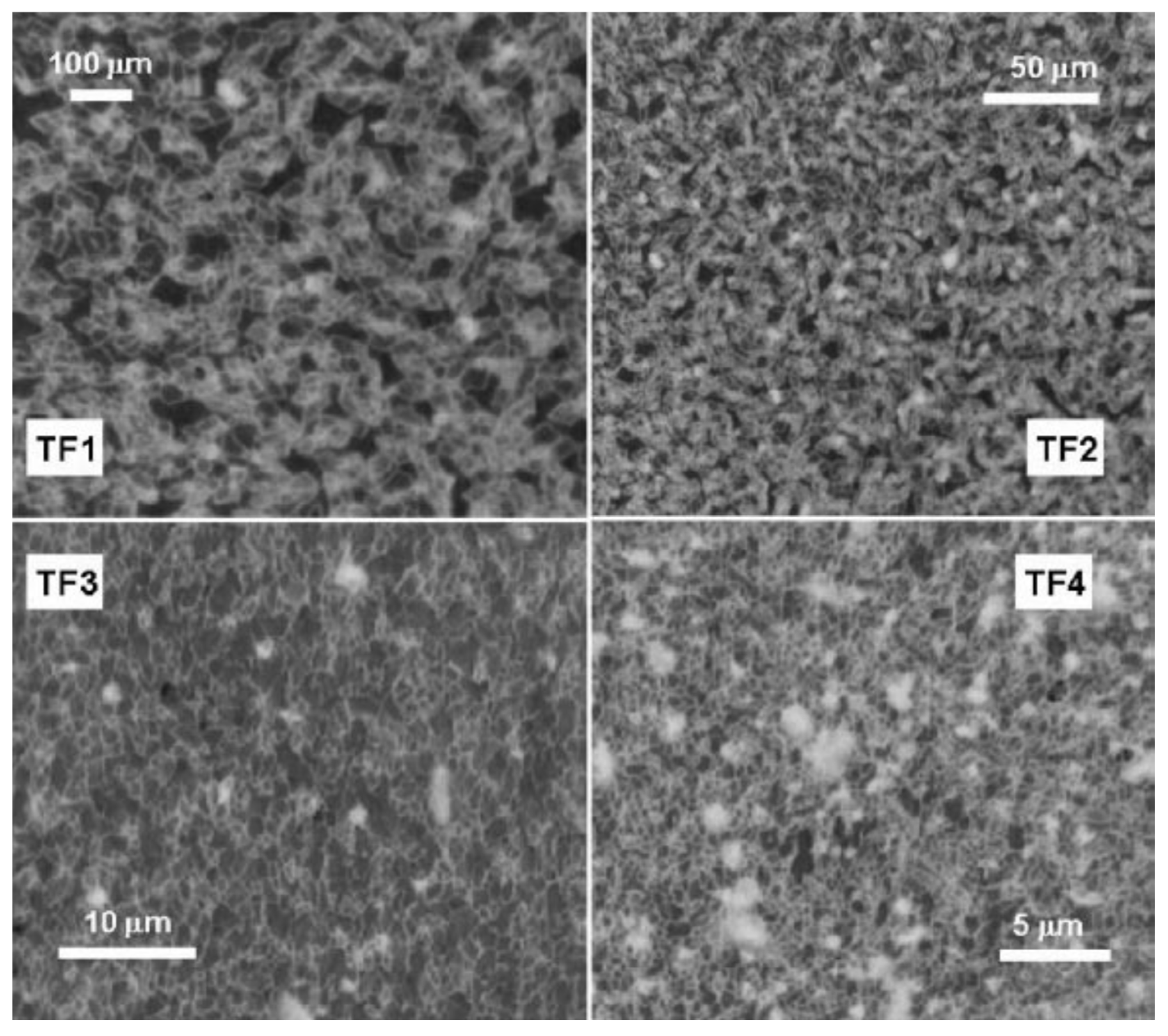
Schön et al. examined how variations in substrate temperature during deposition influence the microstructure and electronic behavior of pentacene films [164]. By adjusting the spacing between the evaporation source and the substrate, they effectively tuned the thermal conditions under which pentacene layers formed. This gradient in growth temperature led to systematic changes in crystal size, with higher thermal energy producing larger grains and reducing grain boundary density, as shown in the optical images of Figure 3. Devices constructed from single-crystal films exhibited peak hole mobility of 3.2 cm2/Vs. In contrast, polycrystalline films grown at progressively cooler temperatures demonstrated degraded performance, with mobilities falling to 2.4, 2.1, 1.2, and eventually 0.2 cm2/Vs. The data revealed that grain boundaries and associated trap states played a great role in suppressing charge transport as deposition temperature dropped. This research offers clear experimental validation of the relationship between processing temperature, film morphology, and device mobility, which makes it highly valuable for guiding thin-film fabrication in organic electronics. By directly linking thermal conditions to grain boundary formation and transport properties, this work provided a practical framework for optimizing semiconductor performance via deposition control. The stark mobility contrast between high- and low-temperature-grown films, which spanned over an order of magnitude, highlights the impact of grain boundary density on charge carrier flow. Moreover, their findings emphasize how trap density escalates with increased boundaries and show the degradation mechanisms that limit the performance and stability of OTFTs.
Minari et al. investigated how charge transport in pentacene is influenced by grain boundaries, based on single-crystal and polycrystalline films [165]. Their study demonstrated that transistors based on single-crystal pentacene exhibited a hole mobility of up to 2 cm2/Vs, which was approximately an order of magnitude higher than devices using polycrystalline pentacene as the active layer. The research also examined the activation energy as a function of applied gate voltage and charge carrier density. In polycrystalline films, the activation energy decreased as the gate voltage increased, indicating that charge transport was dominated by extrinsic traps at grain boundaries. Conversely, in single-crystal pentacene, the activation energy showed only a slight decrease at low gate voltages and remained nearly constant at higher voltages, suggesting that charge transport in these films was governed primarily by thermally activated polarons. This study provides direct evidence of how grain boundaries impact charge transport in organic semiconductors, particularly in pentacene-based devices. By comparing single-crystal and polycrystalline films, this work quantified the impact of grain boundaries on mobility and revealed that polycrystalline films suffer from charge trapping due to extrinsic defects. This work also highlights the importance of activation energy trends in understanding transport mechanisms, distinguishing between intrinsic polaron hopping in single crystals and extrinsic trap-limited transport in polycrystalline films. These insights are fundamental for optimizing the charge transport of organic electronic devices, as they address the need to minimize grain boundaries to achieve higher mobility and better device performance.
Weis et al. investigated how varying crystal sizes in pentacene films affect charge transport properties [166]. Utilizing thermal evaporation, they controlled the deposition rate to produce films with distinct mean crystal sizes: 0.3 µm at 0.5 Å/s and 0.1 µm at 10 Å/s. Field-effect transistor measurements revealed that larger crystals exhibited a hole mobility of 4.3 cm2/Vs, whereas smaller crystals showed a reduced mobility of 0.021 cm2/Vs. Steady-state voltammetry indicated an increased presence of defects, such as pentacene quinones, at the grain boundaries of films with smaller crystals, which suggests heightened sensitivity to environmental factors such as moisture and gases. This correlation between reduced crystal size, elevated defect concentration, and diminished conductivity shows the critical role of grain boundaries in determining the electrical performance of pentacene films. This research explained the impact of microstructural characteristics on the electrical behavior of organic semiconductors. By demonstrating that smaller grain sizes lead to increased defect densities and reduced charge mobility, the study highlights the importance of optimizing deposition conditions to achieve larger crystalline domains. Such optimization is essential for developing pentacene-based applications with improved stability in varying conditions and for enhancing the performance and stability of organic electronic devices.
Jin et al. investigated how grain size influences contact resistance and grain boundary trap density in pentacene-based thin-film transistors [167]. They thermally evaporated pentacene onto substrates at 20 °C and 80 °C and obtained grain sizes of 0.2–0.3 µm and 2–4 µm, respectively. The parasitic resistance was found to be 4.2 ± 0.2 kΩ cm for smaller grains and 1.2 ± 0.2 kΩ cm for larger grains. Correspondingly, grain boundary trap densities were (1.2 ± 0.3) × 1012 cm−2 and (5.6 ± 0.5) × 1011 cm−2, respectively. The highest mobility observed was 0.359 ± 0.002 cm2/Vs for the 80 °C substrate with a 10 µm channel length. This research explains the direct relationship between grain size and key electrical parameters in pentacene-based thin-film transistors. Understanding that larger grains reduce contact resistance and trap density provides valuable information for optimizing organic semiconductor charge transport in high-performance organic electronics.

3.2. TIPS Pentacene

TIPS pentacene is a solution-processable derivative of pentacene widely used in organic electronics [168,169,170,171,172,173,174]. Chemically, it consists of a pentacene backbone functionalized with bulky triisopropylsilylethynyl side groups at positions 6 and 13, which enhance solubility in common organic solvents and allow for low-temperature fabrication through techniques such as spin-coating, drop-casting, and inkjet printing [175,176,177,178,179]. Physically, TIPS pentacene tends to form needle-like or ribbon-shaped crystals with strong anisotropic growth, typically aligning along the crystallographic direction [180,181]. These crystals exhibit high degrees of π-π stacking, which is important for effective charge transport. Electrically, TIPS pentacene exhibits p-type semiconducting behavior, with reported hole mobilities usually reaching 1 cm2/Vs and above in optimized thin-film transistors [182]. While it generally shows lower intrinsic mobility compared to vacuum-deposited pentacene, its solution processability and environmental stability make it highly attractive for roll-to-roll organic electronics. Studying the grain boundaries in TIPS pentacene is essential because, as in other small-molecule semiconductors, the presence of grain boundaries can introduce structural and energetic disorder. These boundaries can trap charge carriers, impact long-range transport, and reduce device performance and reproducibility. Due to the solution-based nature of TIPS pentacene deposition, crystallization dynamics are highly sensitive to processing parameters, which can lead to variable grain morphology and boundary characteristics. As such, controlling and engineering grain boundaries, by means of solvent selection, polymer additives, substrate patterning, or annealing, is a key strategy to enhance mobility and stability.
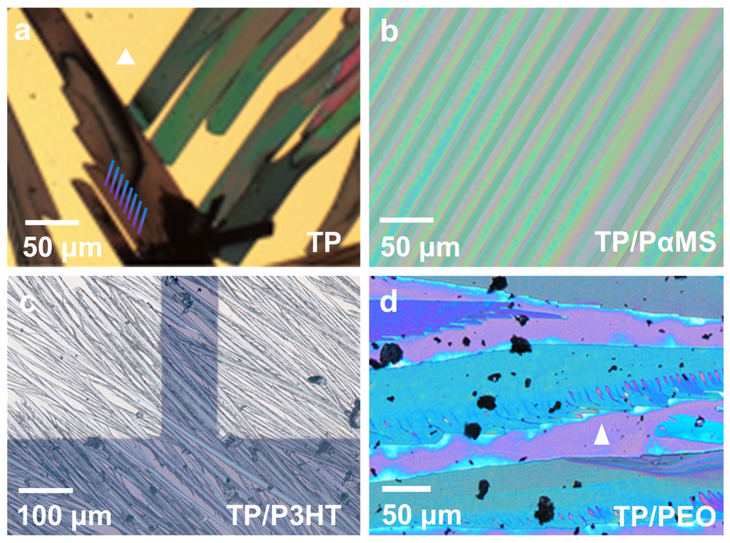
Figure 4 shows the morphological evolution of TIPS pentacene films when blended with different types of polymer additives, including the amorphous polymer PαMS, conjugated polymer P3HT, and semicrystalline polymer PEO, which compares their roles in tuning crystal alignment, grain width, and boundary density [130,181,183]. In the pristine TIPS pentacene film (Figure 4a), randomly oriented crystal needles with poor coverage and large grain widths lead to grain boundaries and mobility variations. Figure 4b shows that blending TIPS pentacene with amorphous PαMS results in elongated, uniformly aligned crystals with nearly full channel coverage and long-range order. Although the grain width decreases slightly, the rigid alignment and vertical phase segregation improve mobility and consistency, with OTFTs reaching 0.26 cm2/Vs. In contrast, the conjugated polymer P3HT (Figure 4c) modulates crystallization through π-π and hydrophobic interactions, yielding diverse morphologies depending on loading. At 2% P3HT, TIPS pentacene forms aligned needles with reduced grain width, but increasing P3HT to 25-50% generates interlinked microwires with further narrowed grains, increasing boundary density. Still, the enhanced crystal order led to a mobility of up to 8.96 × 10⁻² cm2/Vs. Figure 4d demonstrates that semicrystalline PEO enables a unique mechanism of in situ competition between its own crystallization and that of TIPS pentacene, producing highly aligned needles and dense coverage at 5–10% loading. While the grain width remains higher than in P3HT blends, the improved uniformity and interconnectivity yield OTFT mobilities up to 2.5 × 10⁻² cm2/Vs. Therefore, while all three additives effectively control TIPS pentacene morphology and grain structure, each polymer highlights different mechanisms to enhance charge transport: PαMS excels in uniform alignment and consistency, P3HT offers strong grain narrowing through molecular interaction, and PEO achieves high film uniformity via crystallization competition.
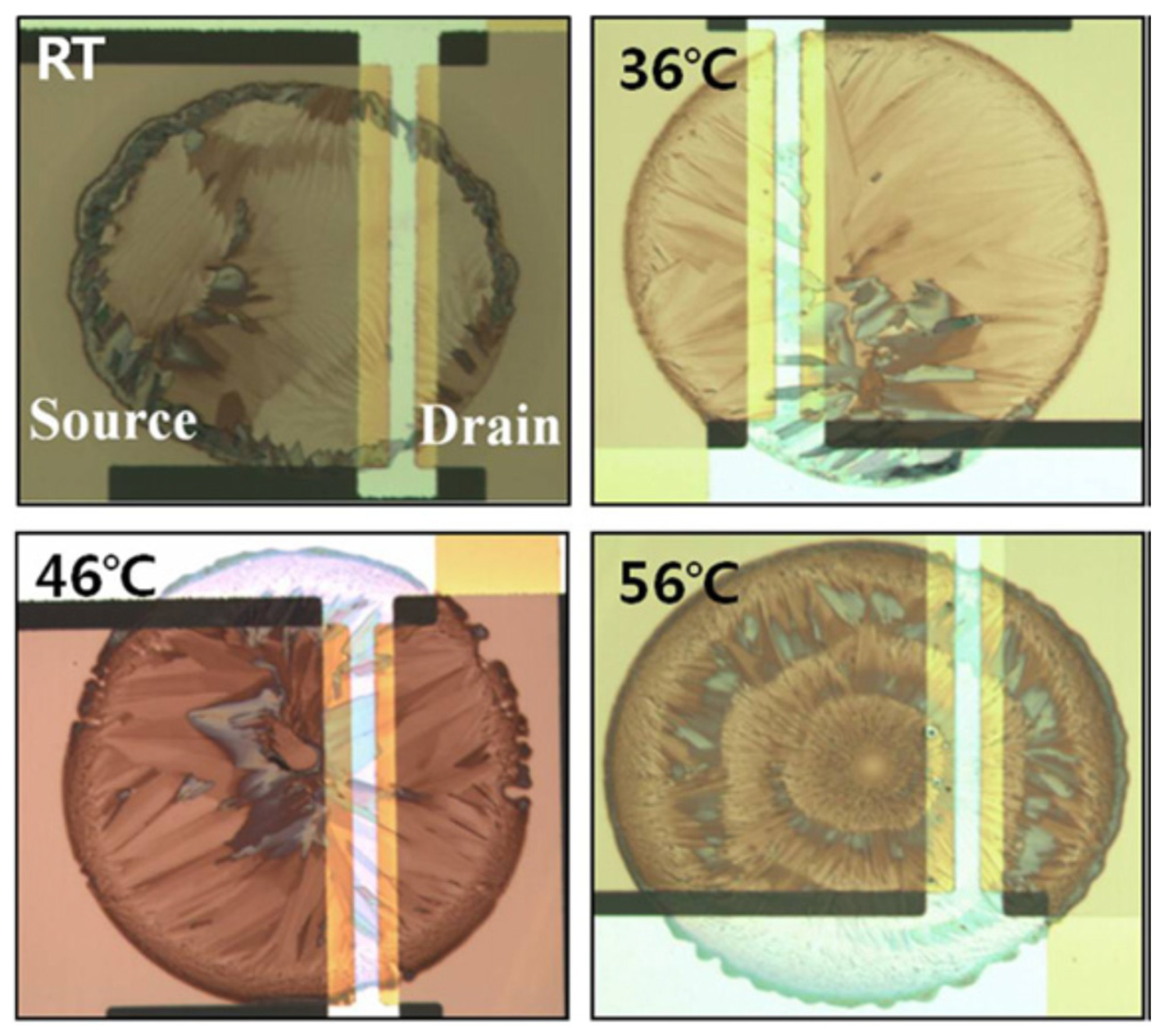
According to a study by Lee et al. [184], the impact of grain boundaries on charge transport in TIPS pentacene inkjet-printed films was examined. In this research, a polyvinyl phenol polymer was first applied as the gate dielectric layer, and then gold was deposited as the source and drain contact electrodes. Next, TIPS pentacene solution was deposited onto the patterned contact electrodes via inkjet printing, while the substrate was held at various temperatures, including room temperature, 36 °C, 46 °C, and 56 °C. The resulting thin-film morphology of the inkjet-printed TIPS pentacene film is depicted in Figure 5. When grown at room temperature, crystals accumulated at the droplet contact line due to the coffee ring effect. Increasing the substrate temperature led to faster solvent evaporation, promoting crystals to grow uniformly from the droplet edge towards the center, resulting in more uniform morphology and crystal alignment. However, excessive evaporation at 56 °C led to smaller crystals with higher grain densities. An average hole mobility of 0.09 ± 0.04 cm2/Vs, 0.21 ± 0.05 cm2/Vs, and 0.07 ± 0.03 cm2/Vs was obtained from the inkjet-printed TIPS pentacene thin-film transistor based on substrate temperatures of 36 °C, 46 °C, and 56 °C, respectively. The mobility at 46 °C increased to 0.44 ± 0.09 cm2/Vs based on multi-drop TIPS pentacene devices, which incorporate grain boundaries in the same direction to minimize the impact of charge trapping sites.

3.3. diF-TES-ADT

Among small-molecule semiconductors used in organic electronics, diF-TES-ADT (2,8-difluoro-5,11-bis(triethylsilylethynyl)anthradithiophene) stands out for its exceptional combination of chemical tunability, physical order, and electronic performance [185,186,187]. This fluorinated anthradithiophene derivative exhibits high ambient stability, strong π-π stacking, and a planar molecular structure that promotes dense crystalline packing [188,189,190,191]. Physically, it forms large lamellar domains with a well-aligned edge-on orientation relative to the substrate, enabling efficient in-plane charge transport. The triethylsilylethynyl side groups enhance solubility, while fluorine substitution improves molecular ordering and air stability [192,193,194]. DiF-TES-ADT has demonstrated hole mobilities exceeding 1 cm2/Vs, making it one of the best-performing semiconductors in solution-processed organic field-effect transistors [195]. Despite its promising attributes, diF-TES-ADT films often exhibit polycrystalline morphologies where grain boundaries can impact charge transport. These boundaries act as traps and resistive barriers that interrupt charge percolation, degrade mobility, and introduce variability in device performance. In flexible electronics, they can also serve as mechanical weak points where cracks initiate under strain. Moreover, the distribution, alignment, and quality of these grain interfaces are highly sensitive to processing conditions such as solvent choice, additives, deposition techniques, and substrate treatment. Thus, understanding and controlling grain boundary formation in diF-TES-ADT is essential for optimizing both electrical and mechanical properties of devices. In this section, we review key studies that explore how solvent engineering, polymer blending, substrate templating, and structural mapping have been used to manipulate the crystallization behavior of diF-TES-ADT and reveal the central role grain boundaries play in limiting or enhancing performance.
Kim et al. investigated how grain boundary structure impacts both the electrical characteristics and mechanical durability of flexible OTFTs using diF-TES-ADT as the active semiconductor [94]. By employing chlorobenzene and toluene as processing solvents, they tuned the crystal morphology of the semiconductor films, resulting in distinct differences in grain size and orientation. Films processed with chlorobenzene exhibited smaller, highly aligned grains that initially supported slightly higher hole mobility (0.87 cm2/Vs) but contained a dense network of sharp grain boundaries. These boundaries introduced deep interfacial voids that acted as mechanical weak points, accelerating crack formation during repeated bending and leading to rapid device failure. In contrast, toluene-processed films formed larger, more randomly oriented grains with fewer, broader grain boundaries that provided better mechanical resilience, allowing devices to retain partial function after 10,000 bending cycles despite slightly lower initial mobility (0.84 cm2/Vs). Their results demonstrate that grain boundaries play a dual role of not only limiting charge transport by introducing trap sites and resistance, but also dictating mechanical robustness by serving as crack initiation points under strain. This study highlights the necessity of grain boundary engineering to achieve a balance between high electrical performance and long-term mechanical reliability in flexible organic electronics.
Rubinger et al. examined how the use of solvent additives influences the crystallization behavior and charge transport of diF-TES-ADT-based OTFTs, with a particular focus on how grain boundaries evolve with processing conditions [194]. By introducing varying volumes of the high-boiling-point additive dichlorobenzene (DCB) into chlorobenzene, they controlled the evaporation dynamics during film formation. The optical micrographs in Figure 6 illustrate a clear trend: as DCB content increases from 0% to 8%, the crystalline domains grow progressively larger and more continuous across the transistor channel. In additive-free films, grain boundaries are abundant, and the contrast between domains indicates misaligned molecular orientations. As DCB is added, slower solvent evaporation extends the crystallization window, facilitating improved molecular packing and domain alignment, which is evident from the more uniform optical contrast between adjacent grains. At 8% DCB, the resulting films display large petal-like domains with fewer boundaries and better orientation continuity, leading to an increase in mobility from 0.12 cm2/Vs to 0.34 cm2/Vs. However, at 10% DCB, excessive solvent retention leads to film dewetting and disrupted coverage, which degrades electrical performance. This work demonstrates that modulating crystallization kinetics through solvent engineering is a powerful strategy to minimize grain boundary density and misorientation, thereby enhancing carrier mobility in printed small-molecule semiconductors.
Naden et al. investigated how microstructural evolution in diF-TES-ADT/polymer blend organic transistors affects charge transport, with an emphasis on domain formation and interfacial boundaries [186]. Using scanning probe techniques such as atomic force microscopy (AFM) and Kelvin probe microscopy (KPM), they identified four distinct regimes of semiconductor crystallization, which ranges from large petal-like crystals nucleated on PFBT-treated Ag electrodes to needle-like and disordered crystallites that emerge further into the channel. Transistors with well-aligned, continuous petal-shaped domains exhibited higher electrical performance, including a peak hole mobility of 1.5 cm2/Vs and on/off ratios of 105. In contrast, devices with disrupted domain connectivity, increased grain boundary density, and needle-like crystallites showed lower mobilities (down to 0.08 cm2/Vs), increased hysteresis, and steeper potential drops across grain interfaces. These findings emphasize that grain boundaries, especially those arising from late-stage nucleation and morphological defects, reduce charge transport by acting as resistive bottlenecks. The study offers direct visual and electrical evidence correlating domain continuity with transistor performance and shows the importance of controlling nucleation kinetics and domain alignment to minimize grain boundary-related degradation in organic transistors.
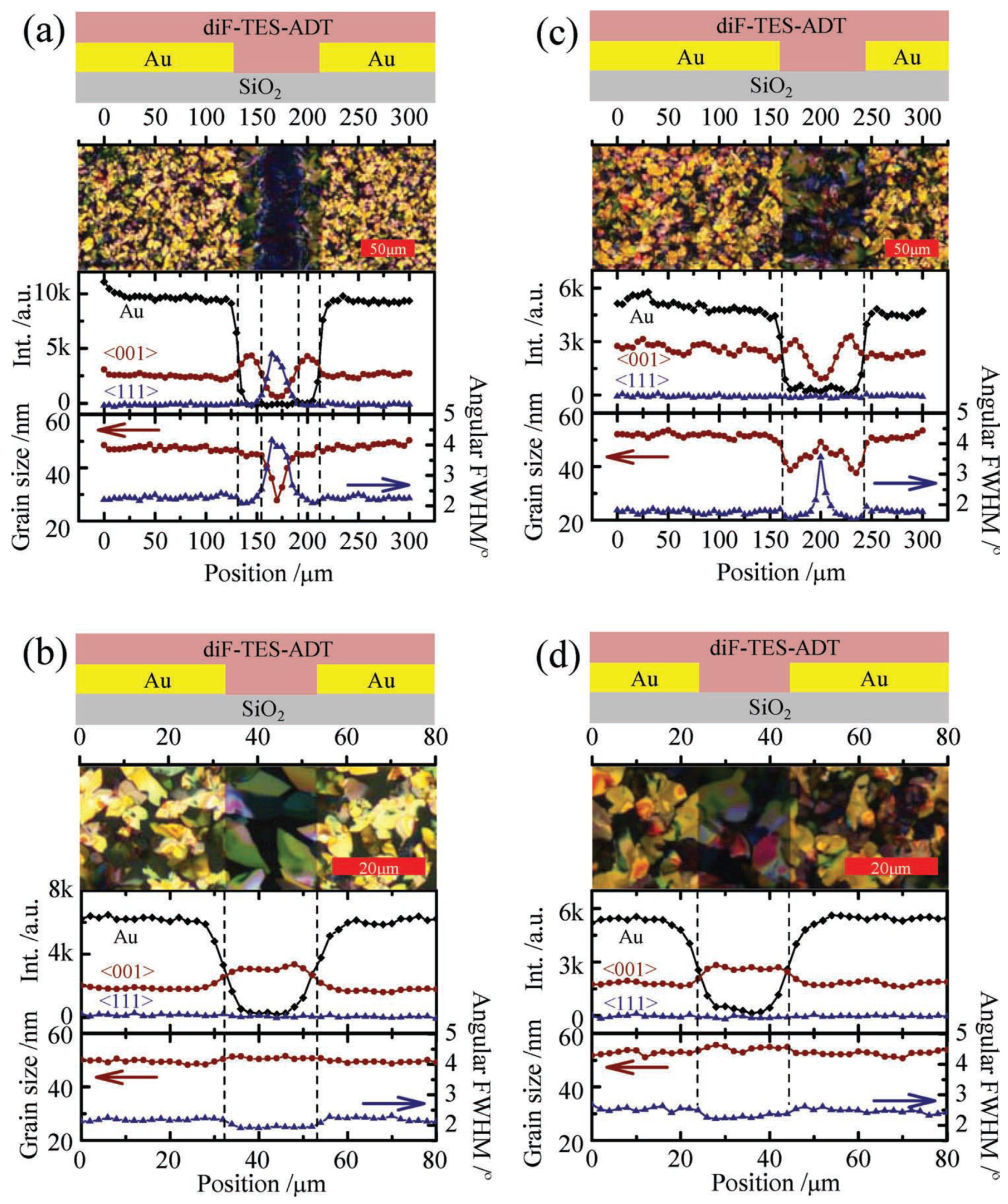
Li et al. performed spatially resolved structural analysis of diF-TES-ADT organic transistors to uncover how domain orientation and microstructural heterogeneity influence charge transport, particularly through grain boundary effects [187]. Using microbeam grazing incidence wide-angle X-ray scattering, they mapped crystallographic textures across devices with channel lengths of 20 μm and 80 μm. Their investigation focused on how processing conditions and substrate treatment impacted the presence and distribution of differently textured crystalline domains and their associated transport bottlenecks. Figure 7 is central to their grain boundary analysis. It presents a side-by-side comparison of microstructural maps from devices of two types: one in which films were grown under standard conditions (type 2), and another processed to enhance crystal continuity (type 1). In type 2 devices, the longer 80 μm channel displayed a spatial transition from the <001> to <111> crystal texture in the channel center. This shift was accompanied by a drop in the intensity of <001> lamellar diffraction, suggesting interrupted grain growth and high-angle misorientation. This break in texture continuity is interpreted as the presence of grain boundaries with disordered interfaces, which are regions likely to impact charge transport due to poor interdomain connectivity. In contrast, the shorter 20 μm type 2 channel retained the <001> texture throughout, indicating that <001>-oriented crystallites successfully bridged the entire span, reducing the likelihood of transport barriers. Type 1 devices, on the other hand, were engineered to promote unbroken <001> crystallization even across the 80 μm channel. These exhibited no detectable <111> textured grains and maintained consistent out-of-plane crystal sizes. Although a sharp increase in angular distribution (FWHM) was observed in the channel center, attributed to grain merging, there was no accompanying strain in the unit cell. Importantly, structural mapping showed that, even when optical and AFM images suggested gaps between domains, the underlying lamellar structure persisted, indicating that traditional imaging may not fully capture the extent of crystalline connectivity relevant to transport. This study directly links specific microstructural transitions, such as texture switching and orientation broadening, to the formation of internal transport barriers, effectively identifying grain boundaries as spatially resolvable limitations to charge mobility. By highlighting that misaligned grain interfaces, rather than just grain size alone, are key contributors to reduced device performance, this study offers a compelling case for using high-resolution structural techniques to optimize grain orientation and connectivity in organic semiconductors.
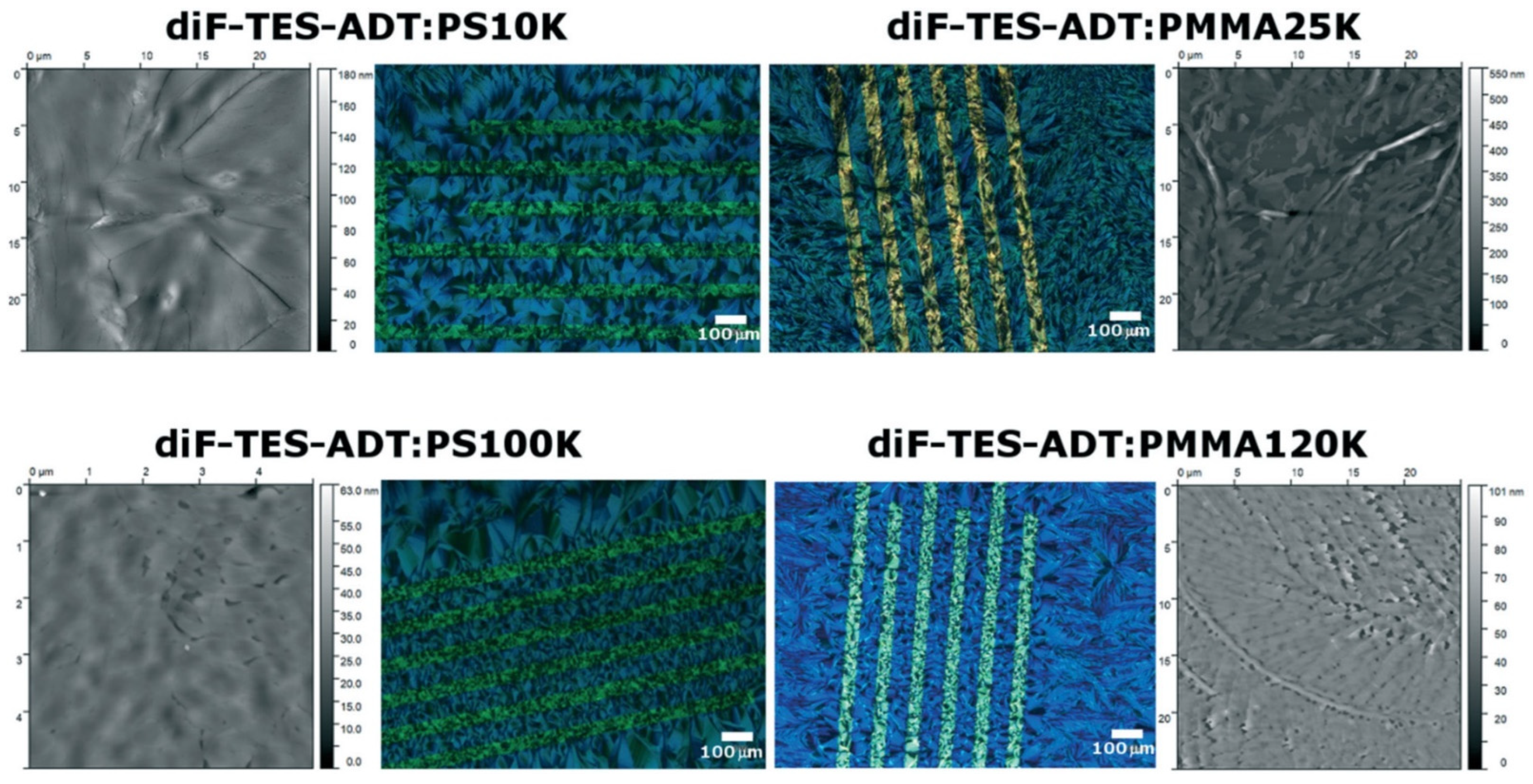
Salzillo et al. explored how the molecular weight and chemical identity of insulating polymer binders influence the crystallization behavior, morphology, and electronic properties of diF-TES-ADT-based organic field-effect transistors [190]. By blending diF-TES-ADT with PS and PMMA of varying molecular weights and depositing the films using bar-assisted meniscus shearing, they achieved a range of microstructures with distinct implications for charge transport. Devices incorporating low-molecular-weight PS (10K) exhibited the highest hole mobility (1.3 cm2/Vs), while PMMA-based devices showed much lower mobility (0.06 cm2/Vs), pointing to the strong influence of blend morphology on performance. Figure 8 provides detailed polarized optical microscopy and AFM comparisons of the thin-film morphologies. Blends with PS (especially 10K molecular weight) produced large, petal-like crystalline domains with clearly defined grain boundaries, forming relatively smooth films with low surface roughness. These well-developed grains with distinct boundaries are advantageous for lateral charge transport, giving rise to high carrier mobility. In contrast, PMMA-blended films displayed a fine-grained, dendritic microstructure with irregular, poorly connected domains and substantially rougher surfaces (RMS roughness 35 nm). These features indicate a high density of disordered grain boundaries that disrupt charge percolation pathways and contribute to interfacial scattering and trapping. The smaller, more fractured domains in PMMA-based blends also point to weaker interactions between the semiconductor and the insulating matrix, leading to poorer film formation and phase segregation. These findings emphasize the dual role of grain boundaries in organic semiconductors: while clearly defined, low-density grain boundaries in PS-based films can support efficient transport, the disordered and densely packed boundaries in PMMA-based blends act as bottlenecks that severely degrade charge mobility. The study demonstrates that both the lateral grain connectivity and vertical phase homogeneity are critical in defining grain boundary characteristics and, hence, device performance.

3.4. Rubrene

Rubrene (C42H28) is a widely studied organic semiconductor, valued for its high hole mobility, which can exceed 10 cm2/Vs in single crystals [196]. Its orthorhombic polymorph features a herringbone molecular packing that promotes strong π-π orbital overlap, enabling efficient in-plane charge transport [197,198,199]. However, when processed into thin films or polycrystalline forms, rubrene often suffers from reduced mobility due to the formation of grain boundaries as interfaces between misoriented crystalline domains that disrupt molecular packing and create energy barriers for charge carriers. These grain boundaries can act as trap sites or resistive bottlenecks, impacting the coherence of band-like transport and introducing thermally activated hopping behavior. As such, understanding and controlling the structure, density, and alignment of grain boundaries is critical for optimizing the electrical performance of rubrene-based organic electronic devices. This section explores recent efforts to characterize the nature of grain boundaries in rubrene films and their impact on charge transport across different morphologies and structural conditions.
Foggiatto et al. studied the local grain boundary structure in crystalline rubrene platelet and spherulite films by using scanning transmission X-ray microscopy [200]. As a result of different thermal annealing conditions, Figure 9a and Figure 9b show the polarized optical microscope images of the rubrene platelet and rubrene spherulite, respectively. Each domain in the rubrene platelet is a single-crystal orthorhombic grain with abrupt grain boundaries, whereas in rubrene spherulite, it is a continuous gradient of film with variations in in-plane orientations and more disordered and wider grain boundaries. Figure 9c shows a plot of the grain boundary in rubrene platelet and rubrene spherulite films. The grain boundary in both films showed misaligned orientations. The RMS in spherulite film is higher than that in the platelet due to the presence of rays from the nucleation sites, indicating the existence of more grain boundaries. Hole mobility values of 4 cm2/Vs and 1 cm2/Vs were reported from the thin-film transistors based on the rubrene platelet and rubrene spherulite, respectively.
Chapman et al. provided direct evidence of how grain boundaries and dislocations impact charge transport in rubrene organic semiconductors [201]. Using synchrotron-based X-ray topography and high-resolution diffraction, they revealed that even in visually uniform crystals, small-angle grain boundaries and linear dislocations can be present, which is identified as low-energy paths for dislocation formation due to their crystallographic orientation. These defects, which are not readily detectable by conventional polarized light microscopy, contribute to increased mosaicity and are likely responsible for the suboptimal mobilities observed in devices fabricated on these rubrene crystals. The study highlights the critical need for advanced structural characterization techniques in evaluating crystalline quality, emphasizing that improvements in grain boundary control are essential to approaching intrinsic mobility limits in organic molecular semiconductors like rubrene. Mobilities of rubrene were reported ranging from 1 to 13 cm2/Vs, with the variability attributed to microstructural imperfections that disrupt crystal continuity and span the active regions of field-effect transistors.
Kim et al. examined the relationship between crystal thickness, surface morphology, and charge transport in rubrene single crystals, which reveals that surface roughness as dense molecular step edges and macrosteps in thicker crystals can serve as effective charge-trapping sites analogous to grain boundaries [202]. They found that thin crystals (0.5 μm) with atomically smooth surfaces and low step densities achieved high hole mobilities averaging 7.1 cm2/Vs and low surface trap densities (9.6 × 1010 cm−2). In contrast, thick crystals (7 μm) exhibited reduced mobility (6.3 cm2/Vs) and elevated trap densities (5.8 × 1011 cm−2), attributed to the disruption of in-plane charge transport by the step edges that force carriers to traverse the less conductive out-of-plane crystallographic direction. These step-induced morphological discontinuities function similarly to grain boundaries by interrupting molecular packing continuity and localizing traps, thus degrading transport even in structurally continuous single crystals. This work shows the importance of treating molecular step edges as quasi-grain boundaries in thick organic crystals and highlights the need for step edge engineering to fully realize the intrinsic transport potential of rubrene.
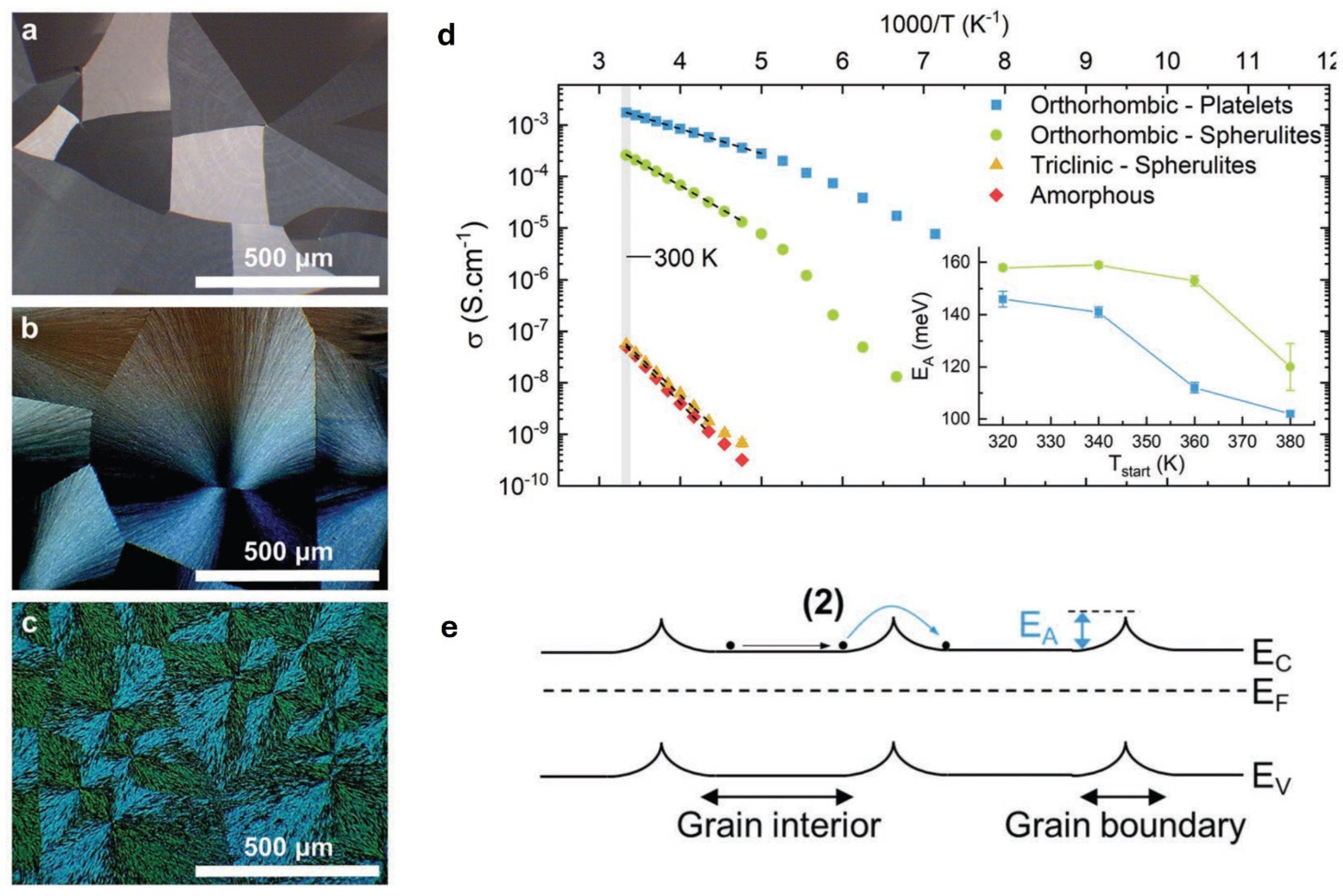
Euvrard et al. investigated the impact of grain boundaries on charge transport in rubrene thin films with varying degrees of structural order, ranging from amorphous to polycrystalline orthorhombic phases [196]. Figure 10a–c visually illustrates the morphological evolution: (a) shows orthorhombic rubrene platelets, where each grain is a large, single-domain crystallite with minimal internal misalignment; (b) presents orthorhombic spherulites, consisting of polycrystalline grains with varying orientation and high grain boundary density; and (c) displays triclinic spherulitic rubrene, which also contains numerous internal grain boundaries and disordered packing. These morphologies directly influence charge transport, as revealed in Figure 10d, where temperature-dependent conductivity measurements show that orthorhombic platelets exhibit the highest conductivity, while spherulitic and triclinic films suffer from increased disorder and resistivity. A key finding is that the thermally activated transport observed in orthorhombic platelets, despite their ordered crystallites, is attributed to energy barriers at grain boundaries, as schematically depicted in Figure 10e. The presence of these grain boundary-induced barriers limits charge mobility, with the orthorhombic platelet films exhibiting a Hall mobility of 2 cm2/Vs. In contrast, increased grain misalignment and disorder in spherulitic morphologies lead to higher activation energies and reduced mobility. This study highlights that even in ostensibly ordered polycrystalline films, grain boundaries serve as critical bottlenecks to transport, emphasizing the need for grain boundary engineering and optimized molecular packing to achieve high mobility in organic semiconductors.
This section reviews case studies demonstrating how grain boundary engineering strategies have been applied to key small-molecule semiconductors. These studies underscore the important role of processing conditions in controlling grain size, orientation, and trap formation, ultimately showing that mitigating grain boundary effects is essential for improving charge transport and device performance in organic semiconductors. The reviewed articles, along with the authors, type of organic semiconductors, result highlights and mobility, are summarized in Table 1. The studies included in Table 1 were selected to represent a broad range of grain boundary engineering strategies applied to high-mobility small-molecule organic semiconductors. These works were chosen based on their experimental clarity, relevance to key themes discussed in this review, and availability of reported mobility values and structural characterization. Together, they provide a comparative overview of how different processing approaches influence film morphology and device performance.

4. Conclusions and Outlook

Grain boundaries are a critical limiting factor in the performance of organic semiconductor devices, particularly in polycrystalline films where they serve as structural and energetic disruptions to charge transport. This review highlights the dual role of grain boundaries, which act as charge trapping sites and electrostatic barriers, that suppress mobility, introduce hysteresis, and compromise both the operational and environmental stability of OTFTs. Across materials systems including pentacene, TIPS pentacene, diF-TES-ADT, and rubrene, it is evident that reducing grain boundary density and misorientation is essential for achieving near-intrinsic transport properties. Strategies such as solvent engineering, polymer additives, and external alignment have been shown to successfully tune crystallization behavior, modulate grain width, and enhance domain connectivity, resulting in substantial mobility gains. The selection of an effective grain boundary regulation strategy is closely tied to the intrinsic structural characteristics of each organic semiconductor. For example, materials with pronounced anisotropic crystal growth, such as TIPS pentacene and diF-TES-ADT, respond well to alignment techniques and polymer additives that facilitate directional crystallization and long-range order. In contrast, semiconductors such as rubrene, which are highly sensitive to processing conditions, could benefit more from solvent engineering to control nucleation density and minimize grain boundary formation. Understanding the molecular packing behavior, crystallization dynamics, and trap susceptibility of a given material is essential for selecting the most suitable engineering approach. In addition, while this review focuses on OTFTs, the grain boundary engineering strategies discussed, such as solvent optimization, polymer blending, and alignment techniques, are broadly applicable to other organic semiconductor devices. In organic photovoltaics, for instance, controlled crystallinity and reduced trap density can enhance charge separation and transport, leading to higher power conversion efficiency. Similarly, in organic light-emitting diodes and sensors, improved molecular ordering can contribute to better charge injection, reduced non-radiative losses, and enhanced operational stability. Therefore, this review offers insights into the design and optimization of a wide range of organic electronic devices.
Despite these advancements, various challenges remain. Future efforts should focus on in situ characterization techniques to dynamically monitor grain boundary formation during film growth, and on developing unified metrics for grain boundary quality beyond width alone, such as misorientation angle, defect density, and boundary chemistry. Moreover, the interplay between grain boundaries and mechanical durability in flexible devices deserves deeper investigation, especially under cyclic strain and real-world conditions. The integration of machine learning with process control could further accelerate the discovery of optimal processing windows for minimizing grain boundaries. Ultimately, the rational design of grain boundary architectures, informed by both empirical data and theoretical modeling, will be key to unlocking the full potential of organic semiconductors in next-generation electronic applications.

Funding

This research received no external funding.

Data Availability Statement

No new data were created or analyzed in this study.

Conflicts of Interest

The authors declare no conflict of interest.

References

  1. Chen, L.; Tang, L.; Ma, H.; Gu, W.; Liu, C.; Jia, X.; Tao, T.; Liu, S.; Chen, Y.; Wang, X.; et al. Application of Highly Spatially Resolved Area Array Velocity Measurement in the Cracking Behavior of Materials. Electronics 2025, 14, 1732. [Google Scholar] [CrossRef]
  2. Sancho-García, J.C.; Pérez-Jiménez, A.J.; Olivier, Y.; Cornil, J. Molecular packing and charge transport parameters in crystalline organic semiconductors from first-principles calculations. Phys. Chem. Chem. Phys. 2010, 12, 9381–9388. [Google Scholar] [CrossRef]
  3. Nelson, J.; Kwiatkowski, J.J.; Kirkpatrick, J.; Frost, J.M. Modeling Charge Transport in Organic Photovoltaic Materials. Acc. Chem. Res. 2009, 42, 1768–1778. [Google Scholar] [CrossRef]
  4. Šiljegović, M.; Cvejić, Ž.; Jankov, S.; Toth, E.; Herceg, D.; Odry, P.; Tadic, V. Impedance and Dielectric Analysis of Nickel Ferrites: Revealing the Role of the Constant Phase Element and Yttrium Doping. Electronics 2024, 13, 1496. [Google Scholar] [CrossRef]
  5. Ryno, S.M.; Risko, C.; Brédas, J.-L. Impact of Molecular Orientation and Packing Density on Electronic Polarization in the Bulk and at Surfaces of Organic Semiconductors. ACS Appl. Mater. Interfaces 2016, 8, 14053–14062. [Google Scholar] [CrossRef]
  6. Li, L.; Hu, W.; Fuchs, H.; Chi, L. Controlling Molecular Packing for Charge Transport in Organic Thin Films. Adv. Energy Mater. 2011, 1, 188–193. [Google Scholar] [CrossRef]
  7. Huang, Y.; Zhang, X.; Ma, F.; Li, J.; Wang, S. A Semi-Supervised Method for Grain Boundary Segmentation: Teacher–Student Knowledge Distillation and Pseudo-Label Repair. Electronics 2024, 13, 3529. [Google Scholar]
  8. Grozema, F.C.; Siebbeles, L.D.A. Mechanism of charge transport in self-organizing organic materials. Int. Rev. Phys. Chem. 2008, 27, 87–138. [Google Scholar] [CrossRef]
  9. Zuo, G.; Abdalla, H.; Kemerink, M. Impact of doping on the density of states and the mobility in organic semiconductors. Phys. Rev. B 2016, 93, 235203. [Google Scholar] [CrossRef]
  10. Wang, L.; Zhou, L.; Wang, X.; You, W. Exploring the Odd–Even Effect, Current Stabilization, and Negative Differential Resistance in Carbon-Chain-Based Molecular Devices. Electronics 2024, 13, 1764. [Google Scholar] [CrossRef]
  11. Roelofs, W.S.C.; Mathijssen, S.G.J.; Janssen, R.A.J.; de Leeuw, D.M.; Kemerink, M. Accurate description of charge transport in organic field effect transistors using an experimentally extracted density of states. Phys. Rev. B 2012, 85, 085202. [Google Scholar] [CrossRef]
  12. Eisensmith, J.D.; Dholabhai, P.P.; Xu, K. Critical Considerations for Observing Cross Quantum Capacitance in Electric-Double-Layer-Gated Transistors Based on Two-Dimensional Crystals. Electronics 2025, 14, 1811. [Google Scholar] [CrossRef]
  13. Baranovskii, S.D. Theoretical description of charge transport in disordered organic semiconductors. Phys. Status Solidi. B 2014, 251, 487–525. [Google Scholar] [CrossRef]
  14. Kasap, S.; Koughia, C.; Berashevich, J.; Johanson, R.; Reznik, A. Charge transport in pure and stabilized amorphous selenium: Re-examination of the density of states distribution in the mobility gap and the role of defects. J. Mater. Sci. Mater. Electron. 2015, 26, 4644–4658. [Google Scholar] [CrossRef]
  15. Morab, S.; Sundaram, M.M.; Pivrikas, A. Charge Transport Characteristics in Doped Organic Semiconductors Using Hall Effect. Electronics 2024, 13, 4223. [Google Scholar] [CrossRef]
  16. Stoneham, A.M.; Gavartin, J.; Shluger, A.L.; Kimmel, A.V.; Muñoz Ramo, D.; Rønnow, H.M.; Aeppli, G.; Renner, C. Trapping, self-trapping and the polaron family. J. Phys. Condens. Matter 2007, 19, 255208. [Google Scholar] [CrossRef]
  17. Thouless, D.J. Electrons in disordered systems and the theory of localization. Phys. Rep. 1974, 13, 93–142. [Google Scholar] [CrossRef]
  18. Jin, H.; Debroye, E.; Keshavarz, M.; Scheblykin, I.G.; Roeffaers, M.B.J.; Hofkens, J.; Steele, J.A. It’s a trap! On the nature of localised states and charge trapping in lead halide perovskites. Mater. Horiz. 2020, 7, 397–410. [Google Scholar] [CrossRef]
  19. Li, G.; Blake, G.R.; Palstra, T.T.M. Vacancies in functional materials for clean energy storage and harvesting: The perfect imperfection. Chem. Soc. Rev. 2017, 46, 1693–1706. [Google Scholar] [CrossRef]
  20. Pezzé, L.; Sanchez-Palencia, L. Localized and Extended States in a Disordered Trap. Phys. Rev. Lett. 2011, 106, 040601. [Google Scholar] [CrossRef]
  21. Doherty, T.A.S.; Winchester, A.J.; Macpherson, S.; Johnstone, D.N.; Pareek, V.; Tennyson, E.M.; Kosar, S.; Kosasih, F.U.; Anaya, M.; Abdi-Jalebi, M.; et al. Performance-limiting nanoscale trap clusters at grain junctions in halide perovskites. Nature 2020, 580, 360–366. [Google Scholar] [CrossRef]
  22. Bai, X.-M.; Uberuaga, B.P. The Influence of Grain Boundaries on Radiation-Induced Point Defect Production in Materials: A Review of Atomistic Studies. JOM 2013, 65, 360–373. [Google Scholar] [CrossRef]
  23. Geng, X.; Vega-Paredes, M.; Wang, Z.; Ophus, C.; Lu, P.; Ma, Y.; Zhang, S.; Scheu, C.; Liebscher, C.H.; Gault, B. Grain boundary engineering for efficient and durable electrocatalysis. Nat. Comm. 2024, 15, 8534. [Google Scholar] [CrossRef]
  24. Wu, Y.; Liu, D.; Chu, W.; Wang, B.; Vasenko, A.S.; Prezhdo, O.V. Point defects at grain boundaries can create structural instabilities and persistent deep traps in metal halide perovskites. Nanoscale 2025, 17, 2224–2234. [Google Scholar] [CrossRef]
  25. Chen, Y.-S.; Lu, H.; Liang, J.; Rosenthal, A.; Liu, H.; Sneddon, G.; McCarroll, I.; Zhao, Z.; Li, W.; Guo, A.; et al. Observation of hydrogen trapping at dislocations, grain boundaries, and precipitates. Science 2020, 367, 171–175. [Google Scholar] [CrossRef]
  26. Sherkar, T.S.; Momblona, C.; Gil-Escrig, L.; Ávila, J.; Sessolo, M.; Bolink, H.J.; Koster, L.J.A. Recombination in Perovskite Solar Cells: Significance of Grain Boundaries, Interface Traps, and Defect Ions. ACS Energy Lett. 2017, 2, 1214–1222. [Google Scholar] [CrossRef]
  27. Li, C.; Duan, L.; Li, H.; Qiu, Y. Universal Trap Effect in Carrier Transport of Disordered Organic Semiconductors: Transition from Shallow Trapping to Deep Trapping. J. Phys. Chem. C 2014, 118, 10651–10660. [Google Scholar] [CrossRef]
  28. Saarinen, K.; Hautojärvi, P.; Vehanen, A.; Krause, R.; Dlubek, G. Shallow positron traps in GaAs. Phys. Rev. B 1989, 39, 5287–5296. [Google Scholar] [CrossRef]
  29. Shuttle, C.G.; Treat, N.D.; Douglas, J.D.; Fréchet, J.M.J.; Chabinyc, M.L. Deep Energetic Trap States in Organic Photovoltaic Devices. Adv. Energy Mater. 2012, 2, 111–119. [Google Scholar] [CrossRef]
  30. Haneef, H.F. Dynamics of Charge Carrier Traps in Organic Semiconductors. Ph.D. Thesis, Wake Forest University, Winston-Salem, NC, USA, 2021. [Google Scholar]
  31. Dundas, K.; Shears, M.J.; Sun, Y.; Hopp, C.S.; Crosnier, C.; Metcalf, T.; Girling, G.; Sinnis, P.; Billker, O.; Wright, G.J. Alpha-v–containing integrins are host receptors for the Plasmodium falciparum sporozoite surface protein, TRAP. Proc. Natl. Acad. Sci. USA 2018, 115, 4477–4482. [Google Scholar] [CrossRef]
  32. Haneef, H.F.; Zeidell, A.M.; Jurchescu, O.D. Charge carrier traps in organic semiconductors: A review on the underlying physics and impact on electronic devices. J. Mater. Chem. C 2020, 8, 759–787. [Google Scholar] [CrossRef]
  33. Wang, F.; Landau, D.P. Determining the density of states for classical statistical models: A random walk algorithm to produce a flat histogram. Phys. Rev. E 2001, 64, 056101. [Google Scholar] [CrossRef]
  34. Lacroix, C. Density of states for the Anderson model. J. Phys. F Met. Phys. 1981, 11, 2389. [Google Scholar] [CrossRef]
  35. Singh, S.; Chopra, M.; de Pablo, J.J. Density of States–Based Molecular Simulations. Annu. Rev. Chem. Biomol. Eng. 2012, 3, 369–394. [Google Scholar] [CrossRef]
  36. Novikov, S.V. Density of states in locally ordered amorphous organic semiconductors: Emergence of the exponential tails. J. Chem. Phys. 2021, 154, 124711. [Google Scholar] [CrossRef]
  37. Zanatta, A.R.; Chambouleyron, I. Absorption edge, band tails, and disorder of amorphous semiconductors. Phys. Rev. B 1996, 53, 3833–3836. [Google Scholar] [CrossRef]
  38. Tsitrin, S.; Williamson, E.P.; Amoah, T.; Nahal, G.; Chan, H.L.; Florescu, M.; Man, W. Unfolding the band structure of non-crystalline photonic band gap materials. Sci. Rep. 2015, 5, 13301. [Google Scholar] [CrossRef]
  39. Yan, X.; Li, B.; Li, L.-S. Colloidal Graphene Quantum Dots with Well-Defined Structures. Acc. Chem. Res. 2013, 46, 2254–2262. [Google Scholar] [CrossRef]
  40. Cooke, D.B.; Tian, Z. Modeling of Organic Thermoelectric Material Properties. In Thin Film and Flexible Thermoelectric Generators, Devices and Sensors; Skipidarov, S., Nikitin, M., Eds.; Springer International Publishing: Cham, Switzerland, 2021; pp. 241–258. [Google Scholar]
  41. Janssen, M. Statistics and scaling in disordered mesoscopic electron systems. Phys. Rep. 1998, 295, 1–91. [Google Scholar] [CrossRef]
  42. Stachurski, Z.H. On Structure and Properties of Amorphous Materials. Materials 2011, 4, 1564–1598. [Google Scholar] [CrossRef]
  43. Pantelides, S.T. The electronic structure of impurities and other point defects in semiconductors. Rev. Mod. Phys. 1978, 50, 797–858. [Google Scholar] [CrossRef]
  44. Huzayyin, A.; Boggs, S.; Ramprasad, R. An overview of impurity states and the basis for hole mobility in polyethylene. IEEE Electr. Insul. Mag. 2012, 28, 23–29. [Google Scholar] [CrossRef]
  45. Grimmeiss, H.G. Deep Level Impurities in Semiconductors. Annu. Rev. Mater. Res. 1977, 7, 341–376. [Google Scholar] [CrossRef]
  46. Wenderott, J.K.; Dong, B.X.; Green, P.F. Morphological design strategies to tailor out-of-plane charge transport in conjugated polymer systems for device applications. Phys. Chem. Chem. Phys. 2021, 23, 27076–27102. [Google Scholar] [CrossRef]
  47. Liu, H.; Liu, D.; Yang, J.; Gao, H.; Wu, Y. Flexible Electronics Based on Organic Semiconductors: From Patterned Assembly to Integrated Applications. Small 2023, 19, 2206938. [Google Scholar] [CrossRef]
  48. Abd Nasir, F.H.; Woon, K.L. Charge carrier trapping in organic semiconductors: Origins, impact and strategies for mitigation. Synth. Met. 2024, 307, 117661. [Google Scholar] [CrossRef]
  49. Xue, J.; Fujitsuka, M.; Tachikawa, T.; Bao, J.; Majima, T. Charge Trapping in Semiconductor Photocatalysts: A Time- and Space-Domain Perspective. J. Am. Chem. Soc. 2024, 146, 8787–8799. [Google Scholar] [CrossRef]
  50. Khanna, V.K. Physical understanding and technological control of carrier lifetimes in semiconductor materials and devices: A critique of conceptual development, state of the art and applications. Prog. Quantum Electron. 2005, 29, 59–163. [Google Scholar] [CrossRef]
  51. Kuik, M.; Wetzelaer, G.-J.A.H.; Nicolai, H.T.; Craciun, N.I.; De Leeuw, D.M.; Blom, P.W.M. 25th Anniversary Article: Charge Transport and Recombination in Polymer Light-Emitting Diodes. Adv. Mater. 2014, 26, 512–531. [Google Scholar] [CrossRef]
  52. Bemski, G. Recombination in Semiconductors. Proc. IRE 1958, 46, 990–1004. [Google Scholar] [CrossRef]
  53. Guo, X.; Waser, R. Electrical properties of the grain boundaries of oxygen ion conductors: Acceptor-doped zirconia and ceria. Prog. Mater. Sci. 2006, 51, 151–210. [Google Scholar] [CrossRef]
  54. Quirk, J.; Rothmann, M.; Li, W.; Abou-Ras, D.; McKenna, K.P. Grain boundaries in polycrystalline materials for energy applications: First principles modeling and electron microscopy. Appl. Phys. Rev. 2024, 11, 011308. [Google Scholar] [CrossRef]
  55. Waser, R.; Hagenbeck, R. Grain boundaries in dielectric and mixed-conducting ceramics. Acta Mater. 2000, 48, 797–825. [Google Scholar] [CrossRef]
  56. Greuter, F.; Blatter, G. Electrical properties of grain boundaries in polycrystalline compound semiconductors. Semicond. Sci. Technol. 1990, 5, 111. [Google Scholar] [CrossRef]
  57. Zhang, Y.; Conibeer, G.; Liu, S.; Zhang, J.; Guillemoles, J.-F. Review of the mechanisms for the phonon bottleneck effect in III–V semiconductors and their application for efficient hot carrier solar cells. Prog. Photovolt. Res. Appl. 2022, 30, 581–596. [Google Scholar] [CrossRef]
  58. Liao, J.-F.; Wu, W.-Q.; Jiang, Y.; Zhong, J.-X.; Wang, L.; Kuang, D.-B. Understanding of carrier dynamics, heterojunction merits and device physics: Towards designing efficient carrier transport layer-free perovskite solar cells. Chem. Soc. Rev. 2020, 49, 354–381. [Google Scholar] [CrossRef]
  59. Horowitz, G.; Hajlaoui, M.E. Grain size dependent mobility in polycrystalline organic field-effect transistors. Synth. Met. 2001, 122, 185–189. [Google Scholar] [CrossRef]
  60. Verlaak, S.; Arkhipov, V.; Heremans, P. Modeling of transport in polycrystalline organic semiconductor films. Appl. Phys. Lett. 2003, 82, 745–747. [Google Scholar] [CrossRef]
  61. Chen, J.H.; Tee, C.K.; Shtein, M.; Anthony, J.; Martin, D.C. Grain-boundary-limited charge transport in solution-processed 6,13 bis(tri-isopropylsilylethynyl) pentacene thin film transistors. J. Appl. Phys. 2008, 103, 114513. [Google Scholar] [CrossRef]
  62. Turnbull, D.; Hoffman, R.E. The effect of relative crystal and boundary orientations on grain boundary diffusion rates. Acta Metall. 1954, 2, 419–426. [Google Scholar] [CrossRef]
  63. Brandon, D.G.; Ralph, B.; Ranganathan, S.; Wald, M.S. A field ion microscope study of atomic configuration at grain boundaries. Acta Metall. 1964, 12, 813–821. [Google Scholar] [CrossRef]
  64. Merkle, K.L.; Smith, D.J. Atomic Structure of Symmetric Tilt Grain Boundaries in NiO. Phys. Rev. Lett. 1987, 59, 2887–2890. [Google Scholar] [CrossRef]
  65. Wolf, D.; Lutsko, J.F. On the geometrical relationship between tilt and twist grain boundaries. Z. Fur. Krist. Mater. 1989, 189, 239–262. [Google Scholar]
  66. Li, M.; Rogatch, M.; Chen, H.; Guo, X.; Tang, J. Supramolecular Design and Assembly Engineering toward High-Performance Organic Field-Effect Transistors. Acc. Mater. Res. 2024, 5, 505–517. [Google Scholar] [CrossRef]
  67. Shuai, Z.; Wang, L.; Li, Q. Evaluation of Charge Mobility in Organic Materials: From Localized to Delocalized Descriptions at a First-Principles Level. Adv. Mater. 2011, 23, 1145–1153. [Google Scholar] [CrossRef]
  68. Lan, X.; Chen, M.; Hudson, M.H.; Kamysbayev, V.; Wang, Y.; Guyot-Sionnest, P.; Talapin, D.V. Quantum dot solids showing state-resolved band-like transport. Nat. Mater. 2020, 19, 323–329. [Google Scholar] [CrossRef]
  69. Lee, J.-S.; Kovalenko, M.V.; Huang, J.; Chung, D.S.; Talapin, D.V. Band-like transport, high electron mobility and high photoconductivity in all-inorganic nanocrystal arrays. Nat. Nanotechnol. 2011, 6, 348–352. [Google Scholar] [CrossRef]
  70. Dong, R.; Han, P.; Arora, H.; Ballabio, M.; Karakus, M.; Zhang, Z.; Shekhar, C.; Adler, P.; Petkov, P.S.; Erbe, A.; et al. High-mobility band-like charge transport in a semiconducting two-dimensional metal–organic framework. Nat. Mater. 2018, 17, 1027–1032. [Google Scholar] [CrossRef]
  71. Alberi, K.; Fluegel, B.; Moutinho, H.; Dhere, R.G.; Li, J.V.; Mascarenhas, A. Measuring long-range carrier diffusion across multiple grains in polycrystalline semiconductors by photoluminescence imaging. Nat. Commun. 2013, 4, 2699. [Google Scholar] [CrossRef]
  72. Gao, Z.; Leng, C.; Zhao, H.; Wei, X.; Shi, H.; Xiao, Z. The Electrical Behaviors of Grain Boundaries in Polycrystalline Optoelectronic Materials. Adv. Mater. 2024, 36, 2304855. [Google Scholar] [CrossRef]
  73. Mataré, H.F. Carrier transport at grain boundaries in semiconductors. J. Appl. Phys. 1984, 56, 2605–2631. [Google Scholar] [CrossRef]
  74. Buscaglia, V.; Buscaglia, M.T.; Viviani, M.; Mitoseriu, L.; Nanni, P.; Trefiletti, V.; Piaggio, P.; Gregora, I.; Ostapchuk, T.; Pokorný, J.; et al. Grain size and grain boundary-related effects on the properties of nanocrystalline barium titanate ceramics. J. Eur. Ceram. Soc. 2006, 26, 2889–2898. [Google Scholar] [CrossRef]
  75. Reisinger, D.; Majewski, P.; Opel, M.; Alff, L.; Gross, R. Hall effect, magnetization, and conductivity of Fe3O4 epitaxial thin films. Appl. Phys. Lett. 2004, 85, 4980–4982. [Google Scholar] [CrossRef]
  76. Lotz, M.R.; Boll, M.; Østerberg, F.W.; Hansen, O.; Petersen, D.H. Mesoscopic current transport in two-dimensional materials with grain boundaries: Four-point probe resistance and Hall effect. J. Appl. Phys. 2016, 120, 134303. [Google Scholar] [CrossRef]
  77. Lim, H.; Lee, M.G.; Kim, J.H.; Adams, B.L.; Wagoner, R.H. Simulation of polycrystal deformation with grain and grain boundary effects. Int. J. Plast. 2011, 27, 1328–1354. [Google Scholar] [CrossRef]
  78. Choi, H.H.; Paterson, A.F.; Fusella, M.A.; Panidi, J.; Solomeshch, O.; Tessler, N.; Heeney, M.; Cho, K.; Anthopoulos, T.D.; Rand, B.P.; et al. Hall Effect in Polycrystalline Organic Semiconductors: The Effect of Grain Boundaries. Adv. Funct. Mater. 2020, 30, 1903617. [Google Scholar] [CrossRef]
  79. Müller, S.; Baumann, R.-P.; Geßner, T.; Weitz, R.T. Identification of grain boundaries as degradation site in n-channel organic field-effect transistors determined via conductive atomic force microscopy. Phys. Status Solidi (RRL)—Rapid Res. Lett. 2016, 10, 339–345. [Google Scholar] [CrossRef]
  80. Bolognesi, A.; Berliocchi, M.; Manenti, M.; Carlo, A.D.; Lugli, P.; Lmimouni, K.; Dufour, C. Effects of grain boundaries, field-dependent mobility, and interface trap States on the electrical Characteristics of pentacene TFT. IEEE Trans. Electron Devices 2004, 51, 1997–2003. [Google Scholar] [CrossRef]
  81. Weitz, R.T.; Amsharov, K.; Zschieschang, U.; Burghard, M.; Jansen, M.; Kelsch, M.; Rhamati, B.; van Aken, P.A.; Kern, K.; Klauk, H. The Importance of Grain Boundaries for the Time-Dependent Mobility Degradation in Organic Thin-Film Transistors. Chem. Mater. 2009, 21, 4949–4954. [Google Scholar] [CrossRef]
  82. Liu, P.; Wang, W.; Liu, S.; Yang, H.; Shao, Z. Fundamental Understanding of Photocurrent Hysteresis in Perovskite Solar Cells. Adv. Energy Mater. 2019, 9, 1803017. [Google Scholar] [CrossRef]
  83. Bercovici, D.; Ricard, Y. Grain-damage hysteresis and plate tectonic states. Phys. Earth Planet. Inter. 2016, 253, 31–47. [Google Scholar] [CrossRef]
  84. Castro-Méndez, A.-F.; Hidalgo, J.; Correa-Baena, J.-P. The Role of Grain Boundaries in Perovskite Solar Cells. Adv. Energy Mater. 2019, 9, 1901489. [Google Scholar] [CrossRef]
  85. Shao, Y.; Fang, Y.; Li, T.; Wang, Q.; Dong, Q.; Deng, Y.; Yuan, Y.; Wei, H.; Wang, M.; Gruverman, A.; et al. Grain boundary dominated ion migration in polycrystalline organic–inorganic halide perovskite films. Energy Environ. Sci. 2016, 9, 1752–1759. [Google Scholar] [CrossRef]
  86. Liu, Y.; Yang, J.; Lawrie, B.J.; Kelley, K.P.; Ziatdinov, M.; Kalinin, S.V.; Ahmadi, M. Disentangling Electronic Transport and Hysteresis at Individual Grain Boundaries in Hybrid Perovskites via Automated Scanning Probe Microscopy. ACS Nano 2023, 17, 9647–9657. [Google Scholar] [CrossRef]
  87. Shen, Y.; Zhang, M.; He, S.; Bian, L.; Liu, J.; Chen, Z.; Xue, S.; Zhou, Y.; Yan, Y. Reliability issues of amorphous oxide semiconductor-based thin film transistors. J. Mater. Chem. C 2024, 12, 13707–13726. [Google Scholar] [CrossRef]
  88. Hao, Z.; Wu, Z.; Liu, S.; Tang, X.; Chen, J.; Liu, X. High-performance organic thin-film transistors: Principles and strategies. J. Mater. Chem. C 2024, 12, 9427–9454. [Google Scholar] [CrossRef]
  89. Yan, A.; Wang, C.; Yan, J.; Wang, Z.; Zhang, E.; Dong, Y.; Yan, Z.-Y.; Lu, T.; Cui, T.; Li, D.; et al. Thin-Film Transistors for Integrated Circuits: Fundamentals and Recent Progress. Adv. Funct. Mater. 2024, 34, 2304409. [Google Scholar] [CrossRef]
  90. Ma, L.-Y.; Soin, N.; Aidit, S.N.; Rezali, F.A.M.; Hatta, S.F.W.M. Recent advances in flexible solution-processed thin-film transistors for wearable electronics. Mater. Sci. Semicond. Process. 2023, 165, 107658. [Google Scholar] [CrossRef]
  91. Watanabe, T. Grain boundary design and control for high temperature materials. Mater. Sci. Eng. A 1993, 166, 11–28. [Google Scholar] [CrossRef]
  92. Langdon, T.G. The role of grain boundaries in high temperature deformation. Mater. Sci. Eng. A 1993, 166, 67–79. [Google Scholar] [CrossRef]
  93. Alexandreanu, B.; Sencer, B.H.; Thaveeprungsriporn, V.; Was, G.S. The effect of grain boundary character distribution on the high temperature deformation behavior of Ni–16Cr–9Fe alloys. Acta Mater. 2003, 51, 3831–3848. [Google Scholar] [CrossRef]
  94. Kim, D.; Ndikumana, J.; Lee, H.; Lee, S.; Yun, Y.; Park, J. Impact of Crystal Domain on Electrical Performance and Bending Durability of Flexible Organic Thin-Film Transistors with diF-TES-ADT Semiconductor. Electron. Mater. Lett. 2025, 21, 1–8. [Google Scholar] [CrossRef]
  95. He, Z.; Zhang, Z.; Asare-Yeboah, K.; Bi, S. Binary solvent engineering for small-molecular organic semiconductor crystallization. Mater. Adv. 2023, 4, 769–786. [Google Scholar] [CrossRef]
  96. Ayub, A.; Ans, M.; Gul, S.; Shawky, A.M.; Ayub, K.; Iqbal, J.; Hashmi, M.A.; Lakhani, A. Toward High-Performance Quinoxaline Based Non-fullerene Small Molecule Acceptors for Organic Solar Cells. Electron. Mater. Lett. 2023, 19, 38–54. [Google Scholar] [CrossRef]
  97. Hou, S.; Zhuang, X.; Fan, H.; Yu, J. Grain Boundary Control of Organic Semiconductors via Solvent Vapor Annealing for High-Sensitivity NO2 Detection. Sensors 2021, 21, 226. [Google Scholar] [CrossRef]
  98. Sun, L.; Li, T.; Zhou, J.; Li, W.; Wu, Z.; Niu, R.; Cheng, J.; Asare-Yeboah, K.; He, Z. A Green Binary Solvent Method to Control Organic Semiconductor Crystallization. ChemistrySelect 2023, 8, e202203927. [Google Scholar] [CrossRef]
  99. Bail, R.; Kang, J.W.; Kang, Y.J.; Chin, B.D. Binary Solvent Effects on Thermally Crosslinked Small Molecular Thin Films for Solution Processed Organic Light-Emitting Diodes. Electron. Mater. Lett. 2021, 17, 74–86. [Google Scholar] [CrossRef]
  100. Lee, Y.; Ho, D.; Valentini, F.; Earmme, T.; Marrocchi, A.; Vaccaro, L.; Kim, C. Improving the charge transport performance of solution-processed organic field-effect transistors using green solvent additives. J. Mater. Chem. C 2021, 9, 16506–16515. [Google Scholar] [CrossRef]
  101. Fo, W.-Z.; Xu, G.Y.; Dong, H.-J.; Liu, L.-N.; Li, Y.W.; Ding, L. Highly Efficient Binary Solvent Additive-Processed Organic Solar Cells by the Blade-Coating Method. Macromol. Chem. Phys. 2021, 222, 2100062. [Google Scholar] [CrossRef]
  102. Liu, R.; Xu, K. Solvent engineering for perovskite solar cells: A review. Micro Nano Lett. 2020, 15, 349–353. [Google Scholar] [CrossRef]
  103. Bharti, D.; Tiwari, S.P. Crystallinity and performance improvement in solution processed organic field-effect transistors due to structural dissimilarity of the additive solvent. Synth. Met. 2016, 215, 1–6. [Google Scholar] [CrossRef]
  104. Ye, L.; Zhang, S.; Ma, W.; Fan, B.; Guo, X.; Huang, Y.; Ade, H.; Hou, J. From Binary to Ternary Solvent: Morphology Fine-tuning of D/A Blends in PDPP3T-based Polymer Solar Cells. Adv. Mater. 2012, 24, 6335–6341. [Google Scholar] [CrossRef]
  105. Li, X.R.; Kjellander, B.K.C.; Anthony, J.E.; Bastiaansen, C.W.M.; Broer, D.J.; Gelinck, G.H. Azeotropic Binary Solvent Mixtures for Preparation of Organic Single Crystals. Adv. Funct. Mater. 2009, 19, 3610–3617. [Google Scholar] [CrossRef]
  106. Sánchez-Camargo, A.d.P.; Bueno, M.; Parada-Alfonso, F.; Cifuentes, A.; Ibáñez, E. Hansen solubility parameters for selection of green extraction solvents. TrAC Trends Anal. Chem. 2019, 118, 227–237. [Google Scholar] [CrossRef]
  107. Gao, J.; Wu, S.; Rogers, M.A. Harnessing Hansen solubility parameters to predict organogel formation. J. Mater. Chem. 2012, 22, 12651–12658. [Google Scholar] [CrossRef]
  108. Lindvig, T.; Michelsen, M.L.; Kontogeorgis, G.M. A Flory–Huggins model based on the Hansen solubility parameters. Fluid Phase Equilibria 2002, 203, 247–260. [Google Scholar] [CrossRef]
  109. Suzuki, I.; Hanna, J.-I.; Iino, H. High-speed blade-coating using liquid crystalline organic semiconductor Ph-BTBT-10. Appl. Phys. Express 2024, 17, 051007. [Google Scholar] [CrossRef]
  110. Hodsden, T.; Thorley, K.J.; Basu, A.; White, A.J.P.; Wang, C.; Mitchell, W.; Glöcklhofer, F.; Anthopoulos, T.D.; Heeney, M. The influence of alkyl group regiochemistry and backbone fluorination on the packing and transistor performance of N-cyanoimine functionalised indacenodithiophenes. Mater. Adv. 2021, 2, 1706–1714. [Google Scholar] [CrossRef]
  111. Chen, M.; Peng, B.; Huang, S.; Chan, P.K.L. Understanding the Meniscus-Guided Coating Parameters in Organic Field-Effect-Transistor Fabrications. Adv. Funct. Mater. 2020, 30, 1905963. [Google Scholar] [CrossRef]
  112. Li, Y.; Tao, R.; He, W.; Chang, C.; Zou, Z.; Zhang, Y.; Wang, D.; Wang, J.; Fan, Z.; Zhou, G.; et al. Realization of tunable artificial synapse through ambipolar charge trapping in organic transistor with pentacene/poly(α-methylstyrene) architecture. J. Appl. Phys. 2021, 129, 074903. [Google Scholar] [CrossRef]
  113. He, H.; He, W.; Mai, J.; Wang, J.; Zou, Z.; Wang, D.; Feng, J.; Zhang, A.; Fan, Z.; Wu, S.; et al. A flexible memory with low-voltage and high-operation speed using an Al2O3/poly(α-methylstyrene) gate stack on a muscovite substrate. J. Mater. Chem. C 2019, 7, 1913–1918. [Google Scholar] [CrossRef]
  114. Xu, W.C.; He, H.X.; Jing, X.S.; Wu, S.J.; Zhang, Z.; Gao, J.W.; Gao, X.S.; Zhou, G.F.; Lu, X.B.; Liu, J.M. High performance organic nonvolatile memory transistors based on HfO2 and poly(α-methylstyrene) electret hybrid charge-trapping layers. Appl. Phys. Lett. 2017, 111, 063302. [Google Scholar] [CrossRef]
  115. Chou, L.-H.; Chang, W.-C.; He, G.-Y.; Chiu, Y.-C.; Liu, C.-L. Controllable electrical performance of spray-coated semiconducting small molecule/insulating polymer blend thin film for organic field effect transistors application. React. Funct. Polym. 2016, 108, 130–136. [Google Scholar] [CrossRef]
  116. He, Z.; Bi, S.; Asare-Yeboah, K.; Chen, J. Study of Grain Boundary: From Crystallization Engineering to Machine Learning. Coatings 2025, 15, 164. [Google Scholar] [CrossRef]
  117. Chen, Z.; Chen, S.; Jiang, T.; Chen, S.; Jia, R.; Xiao, Y.; Pan, J.; Jie, J.; Zhang, X. A floating-gate field-effect transistor memory device based on organic crystals with a built-in tunneling dielectric by a one-step growth strategy. Nanoscale 2024, 16, 3721–3728. [Google Scholar] [CrossRef]
  118. Gubanov, K.; Johnson, M.; Akay, M.; Wolz, B.C.; Shen, D.; Cheng, X.; Christiansen, S.; Fink, R.H. C8-BTBT-C8 Thin-Film Transistors Based on Micro-Contact Printed PEDOT:PSS/MWCNT Electrodes. Adv. Electron. Mater. 2023, 9, 2201233. [Google Scholar] [CrossRef]
  119. Jo, Y.; Lee, J.; Kim, C.; Jang, J.; Hwang, I.; Hong, J.; Lee, M.J. Engineered molecular stacking crystallinity of bar-coated TIPS-pentacene/polystyrene films for organic thin-film transistors. RSC Adv. 2023, 13, 2700–2706. [Google Scholar] [CrossRef]
  120. Tamayo, A.; Hofer, S.; Salzillo, T.; Ruzié, C.; Schweicher, G.; Resel, R.; Mas-Torrent, M. Mobility anisotropy in the herringbone structure of asymmetric Ph-BTBT-10 in solution sheared thin film transistors. J. Mater. Chem. C 2021, 9, 7186–7193. [Google Scholar] [CrossRef]
  121. Yang, Z.; Lin, S.; Liu, J.; Zheng, K.; Lu, G.; Ye, B.; Huang, J.; Zhang, Y.; Ye, Y.; Guo, T.; et al. Sharp phase-separated interface of 6, 13-bis (triisopropylsilylethynyl) pentacene/polystyrene blend films prepared by electrostatic spray deposition. Org. Elect. 2020, 78, 206–210. [Google Scholar]
  122. Li, J.; Tamayo, A.; Quintana, A.; Riera-Galindo, S.; Pfattner, R.; Gong, Y.; Mas-Torrent, M. Binder polymer influence on the electrical and UV response of organic field-effect transistors. J. Mater. Chem. C 2023, 11, 8178–8185. [Google Scholar] [CrossRef]
  123. Rahman, F.; Carbaugh, D.J.; Wright, J.T.; Rajan, P.; Pandya, S.G.; Kaya, S. A review of polymethyl methacrylate (PMMA) as a versatile lithographic resist—With emphasis on UV exposure. Microelectron. Eng. 2020, 224, 111238. [Google Scholar] [CrossRef]
  124. Fan, H.D.; Han, S.J.; Song, Z.H.; Yu, J.S.; Katz, H.E. Organic field-effect transistor gas sensor based on GO/PMMA hybrid dielectric for the enhancement of sensitivity and selectivity to ammonia. Org. Elect. 2019, 67, 247–252. [Google Scholar] [CrossRef]
  125. Hou, S.; Yu, J.; Zhuang, X.; Li, D.; Liu, Y.; Gao, Z.; Sun, T.; Wang, F.; Yu, X. Phase separation of P3HT/PMMA blend film formed semiconducting and dielectric layers in organic thin film transistors for high sensitivity NO2 detection. ACS Appl. Electron. Mater. 2019, 11, 44521–44527. [Google Scholar] [CrossRef]
  126. Xie, Q.; Wang, L.; Zhu, Y.; Sun, Q.; Wang, L. Highly sensitive NO2 sensors based on organic field effect transistors with Al2O3/PMMA bilayer dielectrics by sol-spin coating. Org. Elect. 2019, 74, 69–76. [Google Scholar] [CrossRef]
  127. Jung, S.; Albariqi, M.; Gruntz, G.; Al-Hathal, T.; Peinado, A.; Garcia-Caurel, E.; Nicolas, Y.; Toupance, T.; Bonnassieux, Y.; Horowitz, G. A TIPS-TPDO-tetraCN-Based n-Type Organic Field-Effect Transistor with a Cross-linked PMMA Polymer Gate Dielectric. ACS Appl. Mater. Interfaces 2016, 8, 14701–14708. [Google Scholar] [CrossRef]
  128. Zhang, L.; Yang, D.; Wang, Y.; Wang, H.; Song, T.; Fu, C.; Yang, S.; Wei, J.; Liu, R.; Zou, B. Performance Enhancement of FET-Based Photodetector by Blending P3HT with PMMA. IEEE Photonics Technol. Lett. 2015, 27, 1535–1538. [Google Scholar] [CrossRef]
  129. Agrahari, K.; Chi, M.H.; Priya, S.L.; Cheng, Y.H.; Wang, Y.W. Low voltage driven P3HT/PS phototransistor for ultra-high power efficiency UV sensing. Org. Elect. 2024, 128, 107033. [Google Scholar] [CrossRef]
  130. He, Z.; Zhang, Z.; Bi, S.; Chen, J.; Li, D. Conjugated Polymer Controlled Morphology and Charge Transport of Small-Molecule Organic Semiconductors. Sci. Rep. 2020, 10, 4344. [Google Scholar] [CrossRef]
  131. Shin, H.; Park, J.; Choi, J.S. P-14: Electrical Characteristics of P3HT:TIPS-Pentacene Blend Organic Thin-Film Transistor under Light Irradiation. SID Symp. Dig. Tech. Pap. 2020, 51, 1362–1364. [Google Scholar] [CrossRef]
  132. Poelking, C.; Andrienko, D. Effect of polymorphism, regioregularity and paracrystallinity on charge transport in poly (3-hexylthiophene) [P3HT] nanofibers. Macromolecules 2013, 46, 8941–8956. [Google Scholar] [CrossRef]
  133. Nicho, M.E.; García-Escobar, C.H.; Arenas, M.C.; Altuzar-Coello, P.; Cruz-Silva, R.; Güizado-Rodríguez, M. Influence of P3HT concentration on morphological, optical and electrical properties of P3HT/PS and P3HT/PMMA binary blends. Mater. Sci. Eng. B 2011, 176, 1393–1400. [Google Scholar] [CrossRef]
  134. Benavides, C.M.; Biele, M.; Schmidt, O.; Brabec, C.J.; Tedde, S.F. TIPS Pentacene as a Beneficial Interlayer for Organic Photodetectors in Imaging Applications. IEEE Trans. Electron Devices 2018, 65, 1516–1522. [Google Scholar] [CrossRef]
  135. Ozorio, M.S.; Camacho, S.A.; Cordeiro, N.J.A.; Duarte, J.P.L.; Alves, N. Solvent Effect on Morphology and Optical Properties of Poly(3-hexylthiophene): TIPS-Pentacene Blends. J. Electron. Mater. 2018, 47, 1353–1361. [Google Scholar] [CrossRef]
  136. Ozorio, M.D.; Nogueira, G.L.; Morais, R.M.; Martin, C.D.; Constantino, C.J.L.; Alves, N. Poly(3-hexylthiophene): TIPS-pentacene blends aiming transistor applications. Thin Solid Film. 2016, 608, 97–101. [Google Scholar] [CrossRef]
  137. Mansouri, S.; Mir, L.E.; Al-Ghamdi, A.A.; Al-Hartomy, O.A.; Said, S.A.F.A.; Yakuphanoglu, F. Characterization and modeling of TIPS-pentacene-poly(3-hexyl) thiophene blend organic thin film transistor. Synth. Met. 2013, 185–186, 153–158. [Google Scholar] [CrossRef]
  138. Chen, J.; Shao, M.; Xiao, K.; He, Z.; Li, D.; Lokitz, B.S.; Hensley, D.K.; Kilbey, S.M.; Anthony, J.E.; Keum, J.K.; et al. Conjugated Polymer-Mediated Polymorphism of a High Performance, Small-Molecule Organic Semiconductor with Tuned Intermolecular Interactions, Enhanced Long-Range Order, and Charge Transport. Chem. Mater. 2013, 25, 4378–4386. [Google Scholar] [CrossRef]
  139. Lee, G.; Kim, H.; Lee, S.B.; Kim, D.; Lee, E.; Lee, S.K.; Lee, S.G. Tailored Uniaxial Alignment of Nanowires Based on Off-Center Spin-Coating for Flexible and Transparent Field-Effect Transistors. Nanomaterials 2022, 12, 1116. [Google Scholar] [CrossRef]
  140. Li, W.; Li, L.; Sun, Q.; Liu, X.; Kanehara, M.; Nakayama, T.; Jiu, J.; Sakamoto, K.; Minari, T. Direct fabrication of high-resolution and high-performance flexible electronics via surface-activation-localized electroless plating. Chem. Eng. J. 2021, 416, 127644. [Google Scholar] [CrossRef]
  141. Chen, Z.; Duan, S.; Zhang, X.; Geng, B.; Xiao, Y.; Jie, J.; Dong, H.; Li, L.; Hu, W. Organic Semiconductor Crystal Engineering for High-Resolution Layer-Controlled 2D Crystal Arrays. Adv. Mater. 2021, 34, 2104166. [Google Scholar] [CrossRef]
  142. Zhuang, J.-L.; Terfort, A.; Wöll, C. Formation of oriented and patterned films of metal–organic frameworks by liquid phase epitaxy: A review. Coord. Chem. Rev. 2016, 307, 391–424. [Google Scholar] [CrossRef]
  143. He, Z.; Chen, J.; Sun, Z.; Szulczewski, G.; Li, D. Air-flow navigated crystal growth for TIPS pentacene-based organic thin-film transistors. Org. Elect. 2012, 13, 1819–1826. [Google Scholar] [CrossRef]
  144. Lee, M.W.; Ryu, G.S.; Lee, Y.U.; Pearson, C.; Petty, M.C.; Song, C.K. Control of droplet morphology for inkjet-printed TIPS-pentacene transistors. Microelectron. Eng. 2012, 95, 1–4. [Google Scholar] [CrossRef]
  145. Kim, K.; Hong, J.; Hahm, S.G.; Rho, Y.; An, T.K.; Kim, S.H.; Park, C.E. Facile and Microcontrolled Blade Coating of Organic Semiconductor Blends for Uniaxial Crystal Alignment and Reliable Flexible Organic Field-Effect Transistors. ACS Appl. Mater. Interfaces 2019, 11, 13481–13490. [Google Scholar] [CrossRef]
  146. Kondo, M.; Kajitani, T.; Uemura, T.; Noda, Y.; Ishiwari, F.; Shoji, Y.; Araki, T.; Yoshimoto, S.; Fukushima, T.; Sekitani, T. Highly-ordered Triptycene Modifier Layer Based on Blade Coating for Ultraflexible Organic Transistors. Sci. Rep. 2019, 9, 9200. [Google Scholar] [CrossRef]
  147. Li, C.; Yin, J.; Chen, R.; Lv, X.; Feng, X.; Wu, Y.; Cao, J. Monoammonium Porphyrin for Blade-Coating Stable Large-Area Perovskite Solar Cells with >18% Efficiency. J. Am. Chem. Soc. 2019, 141, 6345–6351. [Google Scholar] [CrossRef]
  148. Wu, D.; Kaplan, M.; Ro, H.W.; Engmann, S.; Fischer, D.A.; DeLongchamp, D.M.; Richter, L.J.; Gann, E.; Thomsen, L.; McNeill, C.R.; et al. Blade Coating Aligned, High-Performance, Semiconducting-Polymer Transistors. Chem. Mater. 2018, 30, 1924–1936. [Google Scholar] [CrossRef]
  149. Lin, Y.Y.; Gundlach, D.J.; Nelson, S.F.; Jackson, T.N. Stacked pentacene layer organic thin-film transistors with improved characteristics. IEEE Electron Device Lett. 1997, 18, 606–608. [Google Scholar] [CrossRef]
  150. Gundlach, D.J.; Lin, Y.Y.; Jackson, T.N.; Nelson, S.F.; Schlom, D.G. Pentacene organic thin-film transistors—Molecular ordering and mobility. IEEE Electron Device Lett. 1997, 18, 87–89. [Google Scholar] [CrossRef]
  151. Brown, A.R.; Jarrett, C.P.; deLeeuw, D.M.; Matters, M. Field-effect transistors made from solution-processed organic semiconductors. Synth. Met. 1997, 88, 37–55. [Google Scholar] [CrossRef]
  152. Nelson, S.F.; Lin, Y.Y.; Gundlach, D.J.; Jackson, T.N. Temperature-independent transport in high-mobility pentacene transistors. Appl. Phys. Lett. 1998, 72, 1854–1856. [Google Scholar] [CrossRef]
  153. Gundlach, D.J.; Jackson, T.N.; Schlom, D.G.; Nelson, S.F. Solvent-induced phase transition in thermally evaporated pentacene films. Appl. Phys. Lett. 1999, 74, 3302–3304. [Google Scholar] [CrossRef]
  154. Anthony, J.E.; Brooks, J.S.; Eaton, D.L.; Parkin, S.R. Functionalized pentacene: Improved electronic properties from control of solid-state order. J. Am. Chem. Soc. 2001, 123, 9482–9483. [Google Scholar] [CrossRef]
  155. Brooks, J.S.; Eaton, D.L.; Anthony, J.E.; Parkin, S.R.; Brill, J.W.; Sushko, Y. Electronic and optical properties of functionalized pentacene compounds in the solid state. Org. Electron. 2001, 1, 301–306. [Google Scholar] [CrossRef]
  156. Knipp, D.; Street, R.A.; Völkel, A.; Ho, J. Pentacene thin film transistors on inorganic dielectrics: Morphology, structural properties, and electronic transport. J. Appl. Phys. 2003, 93, 347–355. [Google Scholar] [CrossRef]
  157. Mattheus, C.C.; Dros, A.B.; Baas, J.; Meetsma, A.; Boer, J.L.d.; Palstra, T.T.M. Polymorphism in pentacene. Acta Crystallogr. Sect. C 2001, 57, 939–941. [Google Scholar] [CrossRef]
  158. Chen, J.H.; Martin, D.C.; Anthony, J.E. Morphology and molecular orientation of thin-film bis(triisopropylsilylethynyl) pentacene. J. Mater. Res. 2007, 22, 1701–1709. [Google Scholar] [CrossRef]
  159. Mattheus, C.C.; Dros, A.B.; Baas, J.; Oostergetel, G.T.; Meetsma, A.; de Boer, J.L.; Palstra, T.T.M. Identification of polymorphs of pentacene. Synth. Met. 2003, 138, 475–481. [Google Scholar] [CrossRef]
  160. Lubert-Perquel, D.; Kim, D.K.; Robaschik, P.; Kay, C.W.M.; Heutz, S. Growth, morphology and structure of mixed pentacene films. J. Mater. Chem. C 2019, 7, 289–296. [Google Scholar] [CrossRef]
  161. Oehzelt, M.; Resel, R.; Suess, C.; Friedlein, R.; Salaneck, W.R. Crystallographic and morphological characterization of thin pentacene films on polycrystalline copper surfaces. J. Chem. Phys. 2006, 124, 054711. [Google Scholar] [CrossRef]
  162. Heringdorf, F.; Reuter, M.C.; Tromp, R.M. Growth dynamics of pentacene thin films. Nature 2001, 412, 517–520. [Google Scholar] [CrossRef]
  163. Edura, T.; Takahashi, H.; Nakata, M.; Tsutsui, K.; Itaka, K.; Koinuma, H.; Mizuno, J.; Wada, Y. Electrical characterization of single grain and single grain boundary of pentacene thin film by nano-scale electrode array. Curr. Appl. Phys. 2006, 6, 109–113. [Google Scholar] [CrossRef]
  164. Schön, J.H.; Kloc, C.; Batlogg, B. On the intrinsic limits of pentacene field-effect transistors. Org. Electron. 2000, 1, 57–64. [Google Scholar] [CrossRef]
  165. Minari, T.; Nemoto, T.; Isoda, S. Fabrication and characterization of single-grain organic field-effect transistor of pentacene. J. Appl. Phys. 2004, 96, 769–772. [Google Scholar] [CrossRef]
  166. Weis, M.; Gmucová, K.; Nádaždy, V.; Majková, E.; Haško, D.; Taguchi, D.; Manaka, T.; Iwamoto, M. Grain Boundary Effect on Charge Transport in Pentacene Thin Films. Jpn. J. Appl. Phys. 2011, 50, 04DK03. [Google Scholar] [CrossRef]
  167. Jin, S.H.; Jung, K.D.; Shin, H.; Park, B.-G.; Lee, J.D. Grain size effects on contact resistance of top-contact pentacene TFTs. Synth. Met. 2006, 156, 196–201. [Google Scholar] [CrossRef]
  168. He, Z.; Asare-Yeboah, K.; Zhang, Z.; Bi, S. Manipulate organic crystal morphology and charge transport. Org. Elect. 2022, 103, 106448. [Google Scholar] [CrossRef]
  169. Hao, Z.; Li, Y.; Deng, Y.; Chen, Z.; Liang, J.; Lu, X.; Zhang, J. High sensitivity flexible organic X-ray detectors with minor TIPS-pentacene/insulator polymer blend active layer. Org. Elect. 2024, 131, 107088. [Google Scholar] [CrossRef]
  170. Suzuki, T.; De Nicola, A.; Okada, T.; Matsui, H. Fully Atomistic Molecular Dynamics Simulation of a TIPS-Pentacene:Polystyrene Mixed Film Obtained via the Solution Process. Nanomaterials 2023, 13, 312. [Google Scholar] [CrossRef]
  171. He, Z.; Zhang, Z.; Bi, S. Tailoring the molecular weight of polymer additives for organic semiconductors. Mater. Adv. 2022, 3, 1953–1973. [Google Scholar] [CrossRef]
  172. Alanazi, F.; Eggeman, A.S.; Stavrou, K.; Danos, A.; Monkman, A.P.; Mendis, B.G. Quantifying Molecular Disorder in Tri-Isopropyl Silane (TIPS) Pentacene Using Variable Coherence Transmission Electron Microscopy. J. Phys. Chem. Lett. 2023, 14, 8183–8190. [Google Scholar] [CrossRef]
  173. Jiang, H.; Peng, B.; Liu, S.; Ren, J.; Yang, W.; Lin, C.; Wu, R.; Chen, H.; Li, H. Bending TIPS-pentacene single crystals: From morphology to transistor performance. J. Mater. Chem. C 2021, 9, 5621–5627. [Google Scholar] [CrossRef]
  174. He, Z.; Zhang, Z.; Bi, S.; Chen, J. Tuning charge transport in organic semiconductors with nanoparticles and hexamethyldisilazane. J. Nanoparticle Res. 2021, 23, 5. [Google Scholar] [CrossRef]
  175. Shin, S.I.; Kwon, J.H.; Kang, H.; Ju, B.K. Solution-processed 6,13-bis(triisopropylsilylethynyl) (TIPS) pentacene thin-film transistors with a polymer dielectric on a flexible substrate. Semicond. Sci. Technol. 2008, 23, 085009. [Google Scholar] [CrossRef]
  176. Kwon, J.H.; Seo, J.H.; Shin, S.I.; Kim, K.H.; Choi, D.H.; Kang, I.B.; Kang, H.; Ju, B.K. A 6,13-bis(Triisopropylsilylethynyl) pentacene thin-film transistor using a spun-on inorganic gate-dielectric. IEEE Trans. Electron Devices 2008, 55, 500–505. [Google Scholar] [CrossRef]
  177. Madec, M.B.; Crouch, D.; Llorente, G.R.; Whittle, T.J.; Geoghegan, M.; Yeates, S.G. Organic field effect transistors from ambient solution processed low molar mass semiconductor-insulator blends. J. Mater. Chem. 2008, 18, 3230–3236. [Google Scholar] [CrossRef]
  178. Lee, S.H.; Choi, M.H.; Han, S.H.; Choo, D.J.; Jang, J.; Kwon, S.K. High-performance thin-film transistor with 6,13-bis(triisopropylsilylethynyl) pentacene by inkjet printing. Org. Elect. 2008, 9, 721–726. [Google Scholar] [CrossRef]
  179. Kang, J.; Shin, N.; Jang, D.Y.; Prabhu, V.M.; Yoon, D.Y. Structure and properties of small molecule-polymer blend semiconductors for organic thin film transistors. J. Am. Chem. Soc. 2008, 130, 12273–12275. [Google Scholar] [CrossRef]
  180. He, Z.; Zhang, Z.; Asare-Yeboah, K.; Bi, S. Solvent Exchange in Controlling Semiconductor Morphology. Electron. Mater. Lett. 2022, 18, 501–518. [Google Scholar] [CrossRef]
  181. He, Z.; Zhang, Z.; Asare-Yeboah, K.; Bi, S. Poly(α-methylstyrene) polymer and small-molecule semiconductor blend with reduced crystal misorientation for organic thin film transistors. J. Mater. Sci. Mater. Electron. 2019, 30, 14335–14343. [Google Scholar] [CrossRef]
  182. He, Z.; Chen, J.; Li, D. Polymer Additive Controlled Morphology for High Performance Organic Thin Film Transistors. Soft Matter. 2019, 15, 5790–5803. [Google Scholar] [CrossRef]
  183. He, Z.; Zhang, Z.; Bi, S.; Asare-Yeboah, K.; Chen, J. Ultra-low misorientation angle in small-molecule semiconductor/polyethylene oxide blends for organic thin film transistors. J. Polym. Res. 2020, 27, 75. [Google Scholar] [CrossRef]
  184. Ryu, G.S.; Lee, M.W.; Jeong, S.H.; Song, C.K. Thermally Dried Ink-Jet Process for 6,13-Bis(triisopropylsilylethynyl)-Pentacene for High Mobility and High Uniformity on a Large Area Substrate. Jpn. J. Appl. Phys. 2012, 51, 051601. [Google Scholar] [CrossRef]
  185. Lee, S.G.; Lee, H.S.; Lee, S.; Kim, C.W.; Lee, W.H. Thickness-dependent electrical properties of soluble acene–polymer blend semiconductors. Org. Elect. 2015, 24, 113–119. [Google Scholar] [CrossRef]
  186. Naden, A.B.; Loos, J.; MacLaren, D.A. Structure–function relations in diF-TES-ADT blend organic field effect transistors studied by scanning probe microscopy. J. Mater. Chem. C 2014, 2, 245–255. [Google Scholar] [CrossRef]
  187. Li, R.; Ward, J.W.; Smilgies, D.-M.; Payne, M.M.; Anthony, J.E.; Jurchescu, O.D.; Amassian, A. Direct Structural Mapping of Organic Field-Effect Transistors Reveals Bottlenecks to Carrier Transport. Adv. Mater. 2012, 24, 5553–5558. [Google Scholar] [CrossRef]
  188. Zhang, X.; Deng, W.; Lu, B.; Fang, X.; Zhang, X.; Jie, J. Fast deposition of an ultrathin, highly crystalline organic semiconductor film for high-performance transistors. Nanoscale Horiz. 2020, 5, 1096–1105. [Google Scholar] [CrossRef]
  189. Kim, C.-H. Bias-stress effects in diF-TES-ADT field-effect transistors. Solid State Electron. 2019, 153, 23–26. [Google Scholar] [CrossRef]
  190. Salzillo, T.; D’Amico, F.; Montes, N.; Pfattner, R.; Mas-Torrent, M. Influence of polymer binder on the performance of diF-TES-ADT based organic field effect transistor. CrystEngComm 2021, 23, 1043–1051. [Google Scholar] [CrossRef]
  191. Chen, Y.; Wang, M.; Zhang, D.; Wang, H.; Deng, W.; Shi, J.; Jie, J. Bilayer-passivated stable dif-TES-ADT organic thin-film transistors. Appl. Phys. Lett. 2021, 119, 183301. [Google Scholar] [CrossRef]
  192. Lee, J.H.; Lee, S.; Anthony, J.E.; Lim, S.; Nguyen, K.V.; Kim, S.B.; Jang, J.; Jang, H.W.; Lee, H.; Lee, W.H. Crystal Engineering Under Residual Solvent Evaporation: A Journey Into Crystallization Chronicles of Soluble Acenes. Small 2024, 20, 2405966. [Google Scholar] [CrossRef]
  193. Yu, L.; Portale, G.; Stingelin, N. Solution-processing of semiconducting organic small molecules: What we have learnt from 5,11-bis(triethylsilylethynyl)anthradithiophene. J. Mater. Chem. C 2021, 9, 10547–10556. [Google Scholar] [CrossRef]
  194. Rubinger, C.P.L.; Haneef, H.F.; Hewitt, C.; Carroll, D.; Anthony, J.E.; Jurchescu, O.D. Influence of solvent additives on the morphology and electrical properties of diF-TES ADT organic field-effect transistors. Org. Electron. 2019, 68, 205–211. [Google Scholar] [CrossRef]
  195. Ndikumana, J.; Kim, J.; Kim, J.Y.; Lee, D.; An, K. A review on 2,8-difluoro-5,11-bis(triethylsilylethynyl)anthradithiophene based organic thin film transistor. Flex. Print. Electron. 2023, 8, 023001. [Google Scholar] [CrossRef]
  196. Euvrard, J.; Gunawan, O.; Kahn, A.; Rand, B.P. From Amorphous to Polycrystalline Rubrene: Charge Transport in Organic Semiconductors Paralleled with Silicon. Adv. Funct. Mater. 2022, 32, 2206438. [Google Scholar] [CrossRef]
  197. Podzorov, V.; Menard, E.; Borissov, A.; Kiryukhin, V.; Rogers, J.A.; Gershenson, M.E. Intrinsic charge transport on the surface of organic semiconductors. Phys. Rev. Lett. 2004, 93, 086602. [Google Scholar] [CrossRef]
  198. Kafer, D.; Ruppel, L.; Witte, G.; Woll, C. Role of molecular conformations in rubrene thin film growth. Phys. Rev. Lett. 2005, 95, 166602. [Google Scholar] [CrossRef]
  199. Zeis, R.; Besnard, C.; Siegrist, T.; Schlockermann, C.; Chi, X.L.; Kloc, C. Field effect studies on rubrene and impurities of rubrene. Chem. Mater. 2006, 18, 244–248. [Google Scholar] [CrossRef]
  200. Foggiatto, A.L.; Takeichi, Y.; Ono, K.; Suga, H.; Takahashi, Y.; Fusella, M.A.; Dull, J.T.; Rand, B.P.; Kutsukake, K.; Sakurai, T. Study of local structure at crystalline rubrene grain boundaries via scanning transmission X-ray microscopy. Org. Electron. 2019, 74, 315–320. [Google Scholar] [CrossRef]
  201. Chapman, B.D.; Checco, A.; Pindak, R.; Siegrist, T.; Kloc, C. Dislocations and grain boundaries in semiconducting rubrene single-crystals. J. Cryst. Growth 2006, 290, 479–484. [Google Scholar] [CrossRef]
  202. Kim, J.J.; Bachevillier, S.; Arellano, D.L.G.; Cherniawski, B.P.; Burnett, E.K.; Stingelin, N.; Ayela, C.; Usluer, Ö.; Mannsfeld, S.C.B.; Wantz, G.; et al. Correlating Crystal Thickness, Surface Morphology, and Charge Transport in Pristine and Doped Rubrene Single Crystals. ACS Appl. Mater. Interfaces 2018, 10, 26745–26751. [Google Scholar] [CrossRef]
  203. Sun, Y.; Zhang, Z.; Asare-Yeboah, K.; Bi, S.; He, Z. Large-Dimensional Organic Semiconductor Crystals with Poly(butyl acrylate) Polymer for Solution-Processed Organic Thin Film Transistors. Electron. Mater. Lett. 2021, 17, 33–42. [Google Scholar] [CrossRef]
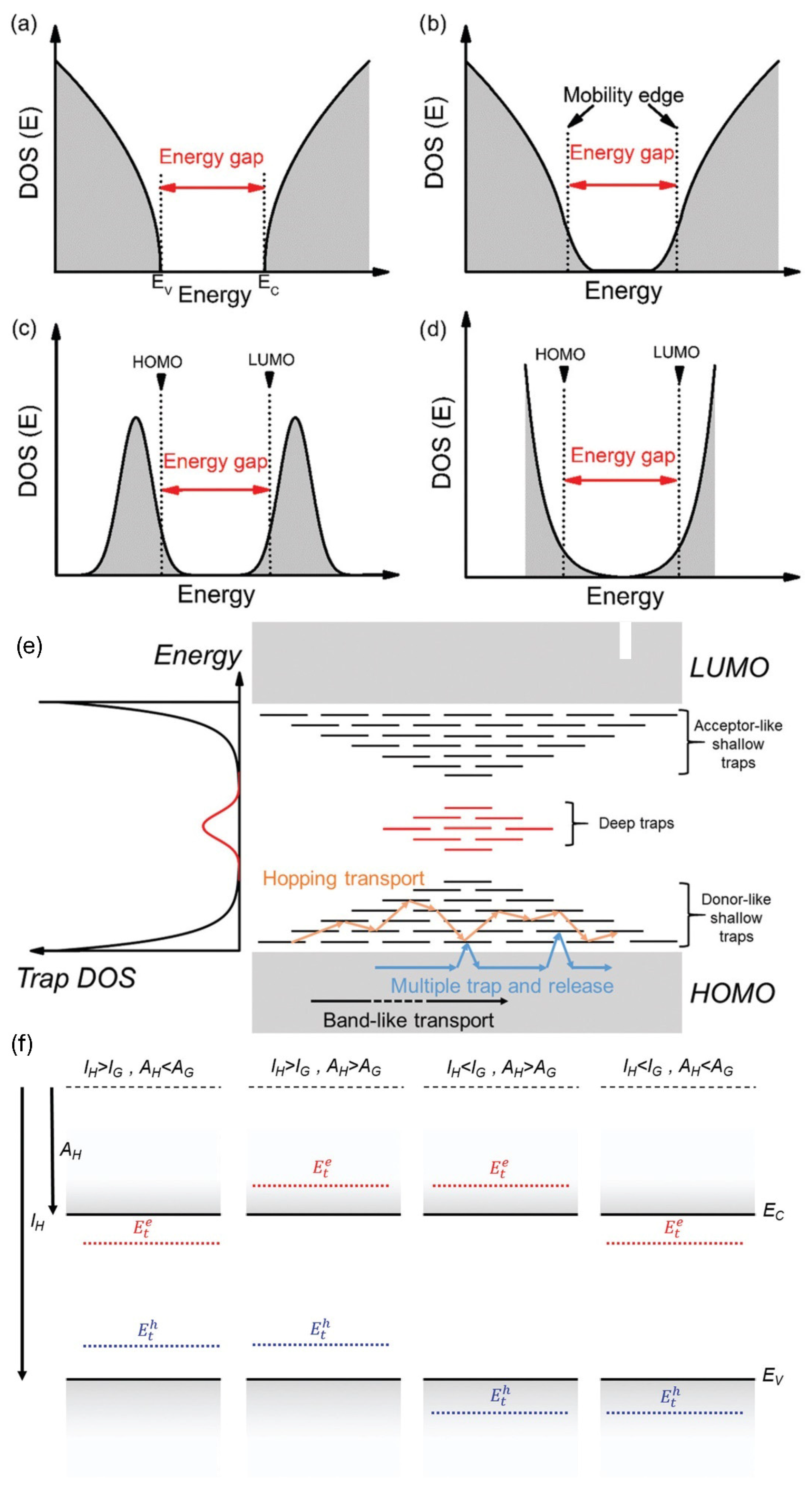
Figure 1. Key concepts are summarized related to DOS and trap states in organic semiconductors. (ad) illustrate DOS for extended states in different material systems: (a) perfectly ordered crystalline OSCs, (b) crystalline OSCs with weak localization, and (c,d) disordered systems modeled by Gaussian and exponential functions. (e) presents a trap DOS profile, with shallow tail states (black) and deeper trap states (red) located within the band gap. The accompanying schematic shows charge transport mechanisms: band-like (black arrows), multiple trap and release (blue arrows), and thermally activated hopping between localized states (orange arrows). (f) depicts the impact of guest molecules on trapping behavior in a host semiconductor. Solid black lines mark the host band edges, while dashed blue and red lines indicate hole and electron trap states, respectively. From left to right, the diagrams show simultaneous trapping of both charge carriers; hole trapping with electron anti-trapping; anti-trapping for both carriers; and electron trapping with hole anti-trapping. IH and IG refer to the ionization energies of the host and guest molecules, respectively, while AH and AG represent the electron affinities of the host and guest, which define the energy offsets for trap formation. Reproduced from reference [32], with permission from The Royal Society of Chemistry.
Electronics 14 03042 g001
Figure 2. (a) Transfer characteristics of two transistors fabricated with TIPS pentacene crystals, showing differences in hysteresis linked to average domain width, approximately 10 μm for Device A and 300 μm for Device B. Polarized optical images reveal that both devices have similar orientation angles (30°) between the crystal growth axis ([210]) and current path, minimizing angular effects on transport. (b) Plot of saturation mobility versus mean crystal width, alongside simulated results based on a model incorporating both elongated and equiaxed domains. A sharp mobility increase occurs near a threshold width of 6 μm, attributed to a structural transition in grain geometry. (c) Schematic of needle-like domains, where grain length (LG) exceeds width (WG), aligned primarily along with small angular deviations. (d) Schematic of equiaxed domains found in narrower grains (WG < 4 μm), where LG and WG are comparable, suggesting isotropic microstructures. Reproduced from reference [61], with permission from AIP Publishing.
Electronics 14 03042 g002
Figure 3. Images showing the different types of pentacene films after depositing at different temperatures, ranging from samples labeled TF1 to those labeled TF4. Note the exact substrate temperatures of TF1 to TF4 were not specified in the source article. Reproduced from reference [164], with permission from Elsevier.
Electronics 14 03042 g003
Figure 4. Polarized optical microscopy images of TIPS pentacene (TP) films mixed with different polymer additives. (a) Pristine TP film exhibits randomly oriented, thick crystals with large gaps and poor uniformity. (b) TP blended with amorphous PαMS shows highly aligned, uniform needle-like crystals with enhanced coverage and directional growth. (c) TP/P3HT blend forms elongated and interconnected microwires with improved long-range order and partial alignment. (d) TP/PEO hybrid film demonstrates uniformly aligned crystal needles with reduced random orientation and improved film continuity, highlighting the effectiveness of semicrystalline PEO in guiding crystal growth. Specifically, the concentrations are 50% for PαMS, 10% for P3HT, and 10% for PEO by weight relative to TIPS pentacene. Reproduced from reference [130,181,183], with permission from Springer Nature.
Electronics 14 03042 g004
Figure 5. The morphologies of TIPS pentacene single droplets at varying drying temperatures (room temperature, 36 °C, 46 °C, and 56 °C) are depicted in optical microscope images. Reproduced from reference [184], with permission from Elsevier.
Electronics 14 03042 g005
Figure 6. Polarized optical microscopy images of diF-TES-ADT processed with varying dichlorobenzene (DCB) additive concentrations: (a) 0%, (b) 2%, (c) 4%, (d) 6%, (e) 8%, and (f) 10% by volume. Increasing DCB content enhances grain size and domain alignment across the channel region (center), while 10% leads to film dewetting and disrupted morphology. Reproduced from reference [194], with permission from Elsevier.
Electronics 14 03042 g006
Figure 7. Spatially resolved microstructural analysis of diF-TES-ADT OTFTs with 80 μm (a,c) and 20 μm (b,d) channel lengths. Each figure shows the device schematic, polarized optical microscopy image, and μGIWAXS-derived maps of <001> and <111> texture intensities, out-of-plane crystal size, and angular orientation distribution (FWHM). Type 2 devices (a,b) show a transition to <111> texture in the center of the longer channel (a), indicating disrupted grain continuity. Type 1 devices (c,d) exhibit consistent <001> texture across both channel lengths, with minor orientation broadening in the 80 μm device, suggesting improved grain bridging and reduced boundary-induced disorder. Reproduced from reference [187], with permission from Wiley.
Electronics 14 03042 g007
Figure 8. Polarized optical microscopy (center color images) and AFM topography images of diF-TES-ADT films blended with PS (10 K), PS (100 K), PMMA (25 K), and PMMA (120 K). PS blends form large, petal-like crystals with clear grain boundaries and low roughness, while PMMA blends show finer, dendritic domains with higher roughness and denser grain boundary networks. Reproduced from reference [190], with permission from The Royal Society of Chemistry.
Electronics 14 03042 g008
Figure 9. Polarized optical microscopic images of (a) rubrene platelet and (b) rubrene spherulite. (c) Different grain boundary regions for (top) rubrene platelet and (bottom) rubrene spherulite films. The black line corresponds to the grain boundary. Reproduced from reference [200], with permission from Elsevier.
Electronics 14 03042 g009
Figure 10. (ac) Polarized optical microscopy images showing morphological variations in rubrene thin films: (a) orthorhombic platelets with large, well-aligned single-domain grains and minimal internal grain boundaries; (b) orthorhombic spherulites comprising radially branching polycrystalline domains with grain boundary density and misorientation; and (c) triclinic spherulites with disordered packing and internal grain boundaries. These morphological differences critically affect the degree of grain boundary formation and thus charge transport behavior. (d) Temperature-dependent conductivity of rubrene films with different morphologies, revealing a four- to five-order magnitude increase in conductivity from amorphous to orthorhombic platelet films. The orthorhombic platelets show thermally activated transport with an activation energy of 120 meV, attributed to energy barriers at grain boundaries, despite having otherwise well-ordered crystalline domains. (e) Schematic illustration of thermally activated charge transport across grain boundaries in polycrystalline films. Energy barriers at grain boundaries act as resistive elements that carriers must overcome, leading to reduced effective mobility and explaining the activation energies observed in otherwise crystalline orthorhombic rubrene films. Reproduced from reference [196], with permission from Wiley.
Electronics 14 03042 g010
Table 1. Summary of the reviewed works, including the authors, semiconductor, result and mobility.
AuthorSemiconductorResult SummaryMobilityReferences
Edura et al.PentaceneCharge transport across single grains was nearly ten times higher than across grain boundaries due to lower resistance5 cm2/Vs[183]
Schön et al.PentaceneHigher substrate temperatures led to larger grains, fewer boundaries, and improved charge mobility3.2 cm2/Vs[164]
Minari et al.PentaceneSingle crystals showed intrinsic polaron hopping, while polycrystalline films were dominated by extrinsic trap-limited transport2 cm2/Vs[165]
Weis et al.PentaceneSmaller grain sizes increased defect concentration and reduced mobility, impacting sensitivity and performance4.3 cm2/Vs[166]
Jin et al.PentaceneLarger grains reduced contact resistance and grain boundary trap density, leading to enhanced charge transport0.359 ± 0.002 cm2/Vs[167]
He et al.TIPS pentaceneBlending TIPS pentacene with PαMS, P3HT, and PEO enables tunable control over crystal alignment, grain width, and film uniformity via distinct mechanisms (amorphous confinement, π-π interaction, and crystallization competition, respectively).0.26 cm2/Vs[130,181,183]
Sun et al.TIPS pentaceneIncorporating PBA into TIPS pentacene enhanced crystal alignment and increased grain width by approximately fivefold0.11 cm2/Vs[203]
Lee et al.TIPS pentaceneInkjet-printed TIPS pentacene films exhibited enhanced crystal alignment and charge mobility by aligning grain boundaries to reduce charge trapping0.44 cm2/Vs[184]
Kim et al.diF-TES-ADTChlorobenzene-processed films had higher initial mobility due to smaller, aligned grains but failed quickly under mechanical stress due to sharp grain boundaries.0.87 cm2/Vs[94]
Rubinger et al.diF-TES-ADTAdding up to 8% dichlorobenzene to chlorobenzene improved crystallization and grain alignment in diF-TES-ADT films, increasing mobility, but excessive additive caused dewetting and performance degradation.0.34 cm2/Vs[194]
Naden et al.diF-TES-ADTdiF-TES-ADT/polymer blend transistors with continuous, well-aligned petal-like domains exhibited higher mobility and lower hysteresis, while disrupted domain connectivity and grain boundaries severely degraded charge transport performance.1.5 cm2/Vs[186]
Li et al.diF-TES-ADTMisoriented grain boundaries, particularly those arising from crystalline texture transitions, severely limit charge transport, whereas promoting continuous grain alignment minimizes boundary-induced barriers and improves mobility.Not reported[187]
Salzillo et al.diF-TES-ADTWell-defined, low-density grain boundaries formed in PS-blended films enhance charge transport, while disordered, high-density grain boundaries in PMMA blends disrupt percolation pathways and reduce mobility.1.3 cm2/Vs[190]
Foggiatto et al.RubreneRubrene spherulites show a wider grain boundary structure with higher RMS4 cm2/Vs[200]
Chapman et al.RubreneSmall-angle grain boundaries and dislocation planes in rubrene single crystals degrade crystalline quality and likely limit charge transport.13 cm2/Vs[201]
Kim et al.RubreneDensely packed molecular step edges in thicker crystals act as grain boundary-like defects that disrupt in-plane transport and increase trap density, thereby reducing charge mobility.7.1 cm2/Vs[202]
Euvrard et al.RubreneGrain boundaries in polycrystalline rubrene films act as energy barriers that limit charge mobility, particularly in orthorhombic spherulitic morphologies, despite overall crystallinity.2 cm2/Vs[196]
Disclaimer/Publisher’s Note: The statements, opinions and data contained in all publications are solely those of the individual author(s) and contributor(s) and not of MDPI and/or the editor(s). MDPI and/or the editor(s) disclaim responsibility for any injury to people or property resulting from any ideas, methods, instructions or products referred to in the content.