Article

A Hybrid Recursive Trigonometric Technique for Direct Digital Frequency Synthesizer

by
Xing Xing
1,
William Melek
1 and
Wilson Wang
2,*
1
Department of Mechanical and Mechatronics Engineering, University of Waterloo, Waterloo, ON N2L 3G1, Canada
2
Department of Mechanical and Mechatronics Engineering, Lakehead University, Thunder Bay, ON P7B 5E1, Canada
*
Author to whom correspondence should be addressed.
Electronics 2025, 14(15), 3027; https://doi.org/10.3390/electronics14153027
Submission received: 8 July 2025 / Revised: 26 July 2025 / Accepted: 27 July 2025 / Published: 29 July 2025
(This article belongs to the Section Circuit and Signal Processing)

Abstract

This paper proposes a Hybrid Recursive Trigonometric (HRT) technique for FPGA-based direct digital frequency synthesizers. The HRT technique integrates a recursive cosine generator with periodic reinitialization via a second-order Taylor polynomial to reduce cumulative errors without requiring ROMs or iterative CORDIC units. A resource-efficient combinational architecture is implemented and validated on the Lattice iCE40HX1K FPGA. The effectiveness of the proposed HRT technique is evaluated through simulation and FPGA-based experiments, with respect to spectral accuracy and resource efficiency, particularly for fixed-point cosine waveform synthesis in low-resource digital systems. Simulation results show that the system has a spurious-free dynamic range (SFDR) of −86.09 dBc and signal-to-noise ratio of 52.74 dB using 16-bit fixed-point arithmetic. Experimental measurements confirm the feasibility, achieving −58.86 dBc SFDR.

1. Introduction

Direct Digital Frequency Synthesizers (DDFSs) are widely used in applications such as digital communication, radar, and instrumentation systems due to their fine frequency resolution, fast frequency switching, and compatibility with digital circuit architectures [1]. A typical DDFS consists of a phase accumulator, a phase-to-amplitude converter (PAC), and/or a digital-to-analog converter (DAC). In early implementations, the PAC is typically realized using large read-only memory (ROM) arrays that store precomputed sine wave samples. While this approach could reach a high accuracy in spectral performance, it entails substantial memory consumption, especially when high phase resolutions or multichannel operations are required [2].
To meet higher performance demands, a variety of alternative PAC architectures were proposed to reduce or eliminate reliance on large ROMs. One such solution was the Coordinate Rotation Digital Computer (CORDIC) algorithm, which computed trigonometric functions through iterative vector rotations only using shift and add operations [3]. CORDIC required no waveform storage and was well-suited to FPGA and ASIC platforms due to its multiplier-free structure. However, its inherently sequential nature and fixed iteration count introduced latency and limited throughput in high-speed applications [4]. Another widely adopted approach was piecewise polynomial approximation, where the waveform was divided into multiple segments and each was independently approximated using low-order polynomials or precomputed coefficients [5]. This method offered localized control over waveform curvatures, errors, and modular hardware design. Nevertheless, transitions between adjacent segments could have introduced derivative discontinuities and/or amplitude mismatches, which degraded spectral performance if they were not properly managed. The choice of segment count and polynomial order presented a trade-off among accuracy, complexity, and implementation overhead. Analytical interpolation methods, particularly those based on Taylor series expansions, were also employed to approximate sine and cosine functions without ROM usage. These methods typically divided the waveform period into finer intervals, where truncated Taylor polynomials were applied at the segment’s boundary or midpoint [6]. Taylor-based implementations were usually simple arithmetically and were attractive for resource-constrained systems. However, they suffered from asymmetric error distributions within each segment, with approximation error increasing toward the edges, particularly when the polynomial order was relatively low. This led to waveform distortion and degraded spectral fidelity [7].
Some limitations in the above approaches have been addressed in recent publications. For example, a modified radix-16 CORDIC structure reduces iteration count to improve convergence speed; however, it still has the sequential latency of classical CORDIC [8]. A midpoint-centered second-order Taylor method in [9] can make simultaneous sine and cosine generation on FPGAs with reduced memory requirements; however, it still has residual edge errors. Random frequency dithering is adopted in [10] to suppress spurious spectral components and improve SFDR, though it does not involve waveform approximation [10]. Some hybrid schemes have been suggested to combine segment-based lookup with polynomial interpolation to balance ROM usage and logic complexity, but they often rely on static segmentation and lack adaptivity to frequency variations [11]. Although some recent developments such as neural network-based calibration for time-interleaved ADCs can improve real-time mismatch correction; however, they demand offline training and additional computational resources, limiting its applicability to compact DDFS systems [12]. Similarly, ultra-low phase noise synthesis using DDFS arrays offers programmable noise shaping for multichannel RF applications but introduces significant system complexity and demands precise synchronization across channels [13]. The Recursive Trigonometric (RT) method provides an alternative approach to generating sine and cosine values through trigonometric recurrence relations [14]. It can eliminate the need for waveform tables or angle rotations and support low-complexity hardware realization. However, due to its recursive nature, the RT method is prone to cumulative errors over long sequences, and its accuracy depends on the initialization and segment structure [15]. Similar concerns regarding cumulative error accumulation in recursive hardware architectures have also been investigated in FPGA-based implementations of neural networks, where reset mechanisms are employed to maintain numerical stability and mitigate hardware-induced inaccuracy [16].
This paper presents a Hybrid Recursive Trigonometric (HRT) technique for FPGA-based DDFS implementation. The proposed HRT technique is new in the following aspects: (1) A recursive cosine generation method is proposed to embed second-order Taylor interpolation at predefined phase positions to reset the computation periodically to limit cumulative numerical errors without requiring ROM-based waveform storage. (2) A compact hardware architecture is designed to eliminate both lookup tables and iterative CORDIC blocks and to enable low-resource FPGA implementation. The effectiveness of the proposed HRT technique is evaluated through both simulation and experimental tests. Simulation results show that the HRT method can achieve an SFDR of −86.09 dBc using 16-bit fixed-point arithmetic, which reaches its theoretical performance limits. Experimental tests on the FPGA demonstrates its feasibility for practical applications, with measured SFDR reaching −58.86 dBc.
The remainder of this paper is structured as follows: Section 2 discusses the design methodology and implementation of the proposed HRT technique. The effectiveness of the HRT technique is verified in Section 3 by simulation and FPGA experimental tests. Some conclusion remarks are summarized in Section 4.

2. Proposed Hybrid RT Technique

2.1. Fundamentals of the RT Technique

In DDFS, the generation of trigonometric waveforms with minimal computational and memory overhead is often required. The RT technique addresses this by computing cosine samples through a second-order recurrence relation derived from trigonometric identities. It can eliminate the need for waveform lookup tables and iterative angle rotations. Each sample is determined solely from the two preceding values, according to the relation:
cos ( ( k + 1 ) θ ) = 2 cos ( θ ) cos ( k θ ) cos ( ( k 1 ) θ )
where θ denotes a fixed phase increment and the index k is an integer that specifies the discrete steps in the recursive sequence. The recurrence begins from two predefined values, commonly cos(0) and cos(θ), and then subsequent cosine samples such as cos(2θ), cos(3θ), and so on, are computed iteratively. This recurrence is derived by substituting the sine expression in the angle addition identity instead of in algebraic forms. The corresponding sine values are not computed directly, but rather obtained through a fixed phase shift such as [17]:
sin ( k θ ) = cos ( π / 2 k θ )
Frequency control is realized through selection of the phase step θ, which is calculated from the desired output frequency fout and the sampling frequency fs:
θ = 2 π · f o u t f s
This formulation allows flexible and continuous frequency synthesis. In practice, for a periodic waveform consisting of m samples per cycle, the phase step is often set to θ = 2π/m. This guarantees that after m iterations, the sequence completes one full period, ensuring waveform continuity at the boundaries and avoiding discontinuities that can cause extra spectral leakage. As demonstrated in the authors’ prior work [15], this phase quantization strategy can be precisely implemented in fixed-point arithmetic using a phase accumulator architecture.
To reduce the total number of recursive steps, the inherent symmetry of the cosine function is frequently applied [17]. Since cosine is both even and periodic over the interval [0, 2π], its values in a single quadrant can be used to reconstruct the entire waveform. In typical implementations, only the samples corresponding to angles between 0 and π/2 (i.e., the first quadrant) are computed recursively. The remaining samples across the full period are reconstructed using index reflection and sign inversion, based on the following quadrant relationships:
cos ( θ ) = cos ( θ ) , θ 0 , π 2 cos ( π θ ) , θ π 2 , π cos ( θ π ) , θ π , 3 π 2 cos ( 2 π θ ) , θ 3 π 2 , 2 π
These symmetry identities ensure all cosine values in a full period to be reconstructed from the first quadrant values. For a waveform sampled at m points per cycle, only the first m/4 samples need to be computed directly via recursion. The remaining 3m/4 samples are obtained through algebraic transformations using the expressions in Equation (4). Although the RT technique can reduce the time of recursive computation based on symmetry identities, numerical error within the computed portion accumulates due to the open-loop nature of the recurrence. Each new sample depends linearly on the two preceding values, so any quantization or rounding error introduced during fixed-point computation is carried forward. As a result, amplitude distortions or deviations from the ideal waveform can occur, particularly when using lower word lengths or extended recursion segments. Increasing the internal word length can enhance numerical accuracy. For example, a 32-bit fixed-point arithmetic provides improved stability over 16-bit implementations. The finer granularity reduces coefficient quantization errors and accumulation errors across the recursive path. However, this comes with increased hardware costs: 32-bit multiplications produce 64-bit intermediate results, necessitating wider registers and more complex logic to avoid overflow and maintain full precision.

2.2. Principle of the Proposed HRT Technique

As shown in Figure 1, the RT technique suffers from progressive amplitude deviation when it is implemented in fixed-point arithmetic. Using 16-bit fixed-point arithmetic, the classical RT method is applied to generate cosine samples across the first quadrant. The error, initially negligible, increase monotonically as the recursion progresses, peaking near the end of the quadrant. Since the full waveform over [0, 2π] is reconstructed through symmetry, the error in the first quadrant is mirrored into the rest of the signal, producing systematic deviations across the entire period. Therefore, it is necessary to control recursive depth to suppress long-chain numerical degradation.
To address this issue, the HRT technique will introduce periodic resets within the recursive sequence. Rather than allowing recursion to span over the entire quadrant, the HRT process is interrupted at fixed intervals and restarted using interpolated values. These values are computed via the second-order Taylor polynomial so as to provide locally accurate seeds that reduce error propagation in subsequent steps [18]. The Taylor series for a general function f(θ) expanded around a reference angle θ0 is given by:
f ( θ ) = i = 1 n f ( i 1 ) ( θ 0 ) ( i 1 ) ! ( θ θ 0 ) i 1
where θ0 is the angle in the recursive sequence near the target interpolation point θ. For the cosine function, the truncated Taylor series can be expressed as:
cos ( θ ) cos ( θ 0 ) 1 2 ( θ θ 0 ) 2 + 1 24 ( θ θ 0 ) 2
The zeroth-degree approximation retains only the constant term cos(θ0) while the second-order Taylor polynomial includes the quadratic curvature term, which can provide improved local accuracy without incurring the complexity of higher-order terms. For a typical DDFS phase increment [19], if ∣θθ0∣ ≤ 0.05 rad, the maximum truncation errors are approximately 6.3 × 10⁻⁴ for the constant approximation, 2.1 × 10⁻⁶ when the quadratic term is included, and 5.2 × 10⁻⁹ after adding the quartic term. The second-order Taylor polynomial therefore reduces the error by two to three orders of magnitude relative to lower-order modes, while requiring only one squaring and one multiplication per reset point. In contrast, including the quartic term introduces the third derivative of cosine, cos’’’(θ0) = sin(θ0), which requires additional approximation, lookup, or evaluation of the sine function. This dependency increases implementation complexity, particularly in fixed-point or resource-constrained environments. As a result, the second-order Taylor polynomial is adopted as a balanced choice in this HTR technique to achieve sufficient accuracy with minimal hardware overhead.
In the HRT technique, the second-order Taylor polynomial is applied not to the initial recursion values but to intermediate reset points located between recursive segments. For a step reset angle θreset and its nearest known recursive reference point θRT, the cosine value is estimated by:
cos ( θ reset ) cos ( θ RT ) 1 2 ( θ reset θ RT ) 2
This approximation leverages the curvature of the cosine function while avoiding the need for sine computation or higher-order derivatives. The interpolated value is then used to reinitialize the recurrence, thereby preventing error propagation from exceeding tolerable bounds over extended sequences. The benefits of this approach can be visualized in Figure 2, which compares the error profiles of the RT and HRT techniques. The RT exhibits a steadily increasing deviation due to accumulation of quantization errors. In contrast, the proposed HRT shows a flat and uniform error distribution across the quadrant.

2.3. Implementation of Taylor-Based Reset Interpolation

To integrate the second-order Taylor polynomial into the RT technique, the HRT technique applies a segmental reset strategy. Rather than propagating the recurrence relation across an entire quadrant, the angle domain is divided into multiple shorter segments. Each segment begins with an interpolated reset point, computed analytically from a nearby known recursive value, and continues with standard recursive updates.
Figure 3 compares the cumulative deviation produced by the RT technique with that of the second-order Taylor polynomial over the interval 0° to 90°. In the initial 0°~30° region, the Taylor curve (dashed) maintains a near-zero error level, substantially lower than the steadily increasing deviation observed in the RT curve (solid blue). This indicates that the second-order Taylor interpolation offers high approximation accuracy in this region and is thus well suited to reset the recursive sequence. Beyond 30°, the Taylor error begins to rise, with a more pronounced growth observed in the 45°~90° intervals. In contrast, the RT error exhibits a consistent monotonic increase across the entire quadrant, reaching the maximum deviation of approximately 0.42 at 90°.
To reflect the dependency on the accuracy of the second-order Taylor approximation, the reset positions are divided into three angular segments: 0°~30°, 30°~60°, and 60°~90°. Within the first segment (0°~30°), where the Taylor-based interpolation remains highly accurate, let R denote the total number of resets applied, and θ be a fixed phase increment. The step reset angle θreset can be calculated by:
θ reset = 90 θ · R
The theoretical truncation error associated with each reset is governed by the Lagrange remainder term of the second-order Taylor polynomial. Based on Equation (7), the third derivative of the cosine function is bounded in magnitude by 1, yielding a worst-case interpolation error bounded by:
E T a y l o r 1 6 · θ r e s e t 3
Since the reset step size θreset for the interval 0°~30°, the error boundary ETaylor decays at a cubic rate as the number of reset points R increases. Equation (9) provides a theoretical basis for selecting an appropriate value of R to ensure that the interpolation error remains within the desired limit.
Figure 4 presents the cumulative error profiles of the HRT technique compared with the second-order Taylor polynomial over the interval 0°~45°, under different reset configurations. In Figure 4a, where two resets are applied, the HRT curve displays three recursive segments, each of which is interrupted by a reset, but the error still grows significantly toward the end of the interval, exceeding 0.03. Figure 4b increases the reset count to four, resulting in visibly improved accuracy and better alignment with the Taylor baseline, although slight divergence remains in the higher-angle region. In Figure 4c, the use of eight resets yields a curve that closely follows the Taylor approximation, with the maximum deviation being reduced to less than 0.015. Finally, Figure 4d shows the result of sixteen resets, where the HRT error becomes nearly indistinguishable from the Taylor reference, reaching a maximum deviation of approximately 1.08 × 10⁻², compared to 1.06 × 10⁻² for the Taylor curve. This indicates that the HRT technique achieves comparable accuracy to the second-order Taylor expansion at sixteen resets and further increases in reset count would offer negligible improvement.
Figure 5 extends the evaluation into the 30°~60° segment to assess whether the same reset strategy remains effective in a region of increased waveform curvature. In the two-reset configuration, illustrated in Figure 5a, the root-mean-square (RMS) error attains 6.29 × 10⁻³; this relatively large value is largely inherited from residual deviation at the transition out of the 0°~30° segment, where only limited reset occurs before the curvature starts to increase. When the reset density is doubled to four, as depicted in Figure 5b, the RMS error falls to 5.38 × 10⁻³, the lowest among all cases examined, confirming that additional mid-interval correction is needed once the waveform departs from the region of highest Taylor fidelity. Increasing the frequency further to eight and sixteen resets, shown in Figure 5c,d, does not yield additional benefit; the corresponding RMS errors rise slightly to 5.91 × 10⁻³ and 6.16 × 10⁻³, respectively. These degradations are primarily attributed to quantization noise and finite word-length rounding in 16-bit arithmetic, which become the dominant error sources when the approximation error from the second-order Taylor polynomial is already low. Among the tested configurations, applying four resets provides the smallest deviation while maintaining a moderate computational burden.
Extending the analysis to the 60°~90° range, Figure 6 demonstrates the investigation on whether additional resets improve accuracy in this higher-angle segment. The error behavior in this interval differs from that observed at lower angles. In Figure 6a, where no resets are applied, the HRT curve remains below the second-order Taylor baseline and exhibits a comparatively shallow growth throughout the interval, reflecting the lower curvature of the cosine function near 90°. Introducing one, two, or four resets, as displayed in Figure 6b–d, produces only minor changes in the error trend and occasionally adds small fluctuations attributable to extra numerical operations. Since the dominant errors here originate from quantization and rounding in 16-bit fixed-point arithmetic rather than from model inaccuracy, additional resets do not yield meaningful improvement. Consequently, omitting resets in the 60°~90° segment maintains numerical stability while avoiding unnecessary computational overhead.
A comprehensive comparison among the RT, second-order Taylor polynomial, and HRT techniques is presented in Figure 7. Based on the cumulative error analysis shown in Figure 4, Figure 5 and Figure 6, the number of reset points in each angular segment is determined to achieve a practical trade-off between numerical accuracy and implementation efficiency. Based on the cumulative error trends observed in Figure 4, Figure 5 and Figure 6, the number of resets in each angular segment is selected to balance accuracy and implementation complexity. For the 0°~30° segment, increasing the reset count from 2 to 16 progressively can reduce the cumulative error. With 16 resets, the error closely matches the second-order Taylor baseline, indicating effective suppression of recursive deviation. Although configurations such as 14 or 15 resets are not explicitly tested, the convergence trend suggests that 16 resets offer a conservative and robust choice. Moreover, 16 aligns with power-of-two segmentation, simplifying FPGA control logic. Reducing the count may lead to variable error performance, while further increase in the reset count provides negligible benefit. For the 30°–60° segment, four resets yield the lowest RMS error, with additional resets offering no clear improvement and slightly increasing quantization noise. Thus, four is selected as a practical compromise between accuracy and resource use. In the 60°~90° segment, additional resets show minimal impact, as the error is dominated by quantization rather than recursive accumulation. Therefore, no resets are applied in this range to maintain computational simplicity. This segment-specific reset strategy is established through quantitative analysis rather than empirical preference, which enables the HRT technique to achieve improved accuracy while maintaining efficient hardware resource utilization.

3. Measurement Results and Analysis

The proposed HRT DDFS design will be implemented on an FPGA circuit for testing because multiplication operations can be performed effectively in the FPGA hardware environment. In typical embedded processors (or ASICs) multiplication tends to be the most resource-consuming and delay-sensitive operation. However, FPGA architectures offer dedicated multiplier blocks (or DSP slices) that enable fast and area-efficient fixed-point multiplications [20]. This characteristic makes FPGA a favorable platform for evaluating the recursive and arithmetic-intensive structure of the HRT technique under practical hardware constraints. To validate the functional correctness and assess hardware feasibility, the proposed architecture is implemented on the Lattice iCE40™ HX1K FPGA. This device belongs to the resource-constrained and ultra-low-power iCE40 family, which will serve as a constrained digital platform for testing designs intended for compact embedded systems.
As shown in Figure 8, the implementation consists of four primary modules: a phase accumulator that generates incremental phase addresses, a reset controller that determines when to inject Taylor-derived reset values, a recursive computation unit that executes the RT calculation, and a symmetric module that maps the computed output to the correct quadrant based on cosine waveform properties. All signals within the HRT system are represented using a 16-bit signed fixed-point format, to ensure uniformity across modules and compatibility with the target FPGA’s arithmetic resources. The phase accumulator, in contrast to conventional DDFS architectures, serves as an address generator for waveform lookup tables, and functions as a counter to output the instantaneous phase angle at each computation cycle. This phase information is used not only to identify the active quadrant, but also to determine whether a reset condition is satisfied. The reset controller is configured according to the angular allocation strategy discussed in Section 2.3, which operates by maintaining an internal counter synchronized with the recursive computation. This counter is compared against two predefined thresholds, corresponding to reset intervals that require 16 and 4 reinitializations, respectively, within their assigned angular segments. When a threshold is met, the controller triggers a reset by activating a Taylor interpolation module to compute a new cosine seed that is routed through a multiplexer to update the recursive state, thereby suppressing cumulative numerical errors. The logic structure of this reset mechanism is illustrated in Figure 9. Between resets, the recursive computation module updates the cosine output based on the RT difference relation given in Equation (1). To preserve the fixed-point resolution during multiplication, the coefficient 2cos(θ) exceeding the ±1 range, is represented using 17 bits—one sign bit and 16 fractional bits. When multiplied with a 16-bit signed fixed-point cosine value (1 sign bit and 15 fractional bits), the operation produces a 33-bit intermediate result. This product is right-shifted by 15 bits to recover the 16-bit format, to ensure consistent resolution across recursive stages without overflow. The symmetry module then processes the final 16-bit output according to the quadrant logic determined by the phase accumulator, and to apply sign inversion and sample reflection as required. The output remains in 16-bit signed fixed-point format throughout, to support direct interfacing with downstream digital signal processing blocks or DAC modules. Since the proposed HRT architecture preserves the iterative and pipeline-compatible structure introduced in previous work [15], its timing characteristics remain unchanged. Therefore, the focus of the present study is not to readdress cycle-level timing comparisons but to enhance spectral accuracy by mitigating recursive numerical errors through the proposed Taylor-based reset strategy.

3.1. Simulation Result

The HRT DDFS architecture will be verified through cycle-accurate simulations using ModelSim SE-64 2020.4, a digital logic tool maintained by Siemens EDA. The Verilog implementation of the architecture is simulated with fixed-point arithmetic, and the output waveform is collected over multiple periods for further analysis. The resulting time-domain data are exported and processed in MATLAB R2024b to evaluate the spectral characteristics. As shown in Figure 10, the synthesized waveform corresponds to a fundamental output frequency of approximately 0.695 MHz. The DDFS operates with a system clock (sampling rate) of fs = 50 MHz and uses an angular step size of θ = 5°, which defines the frequency resolution and controls the rate of recursive updates. After windowing and FFT spectral analysis, the measured spurious-free dynamic range (SFDR) is −86.09 dBc.
In addition to the simulation results, the theoretical SFDR limit for a uniformly quantized sinusoidal waveform with 15 effective bits is approximately −91.82 dBc, as determined by the expression [21]:
SFDR   6.02 × N + 1.76
where N = 15 represents the number of effective quantization bits. This theoretical bound serves as a reference for assessing the practical spectral fidelity of fixed-point DDS implementations.
Table 1 summarizes the SFDR performance of the proposed HRT technique alongside several algorithms, including Radix-2 CORDIC [3], second-order Taylor expansion [9] without segment, piecewise interpolation [22], and RT [15] methods. While all designs employ 16-bit signed fixed-point arithmetic, the actual spectral purity is limited by internal bit alignment, quantization effects, and symmetry logic. The Radix-2 method yields an SFDR of −42.45 dBc, as its shift-and-add logic introduces significant spectral distortion due to low approximation precision. The piecewise polynomial approach enhances local accuracy to −63.02 dBc, though residual discontinuities at segment boundaries limit further enhancement. The second-order Taylor method attains −82.02 dBc by employing smooth polynomial expansion around selected points, enabling improved harmonic suppression. The RT method records −52.31 dBc, constrained by cumulative recursive error in the absence of resets. The proposed HRT technique achieves the highest SFDR at −86.09 dBc, which can reduce spectral artifacts through periodic Taylor reinitialization and phase symmetry processing and narrow the gap to the 16-bit signed fixed-point theoretical limit of −91.82 dBc to 5.73 dBc.

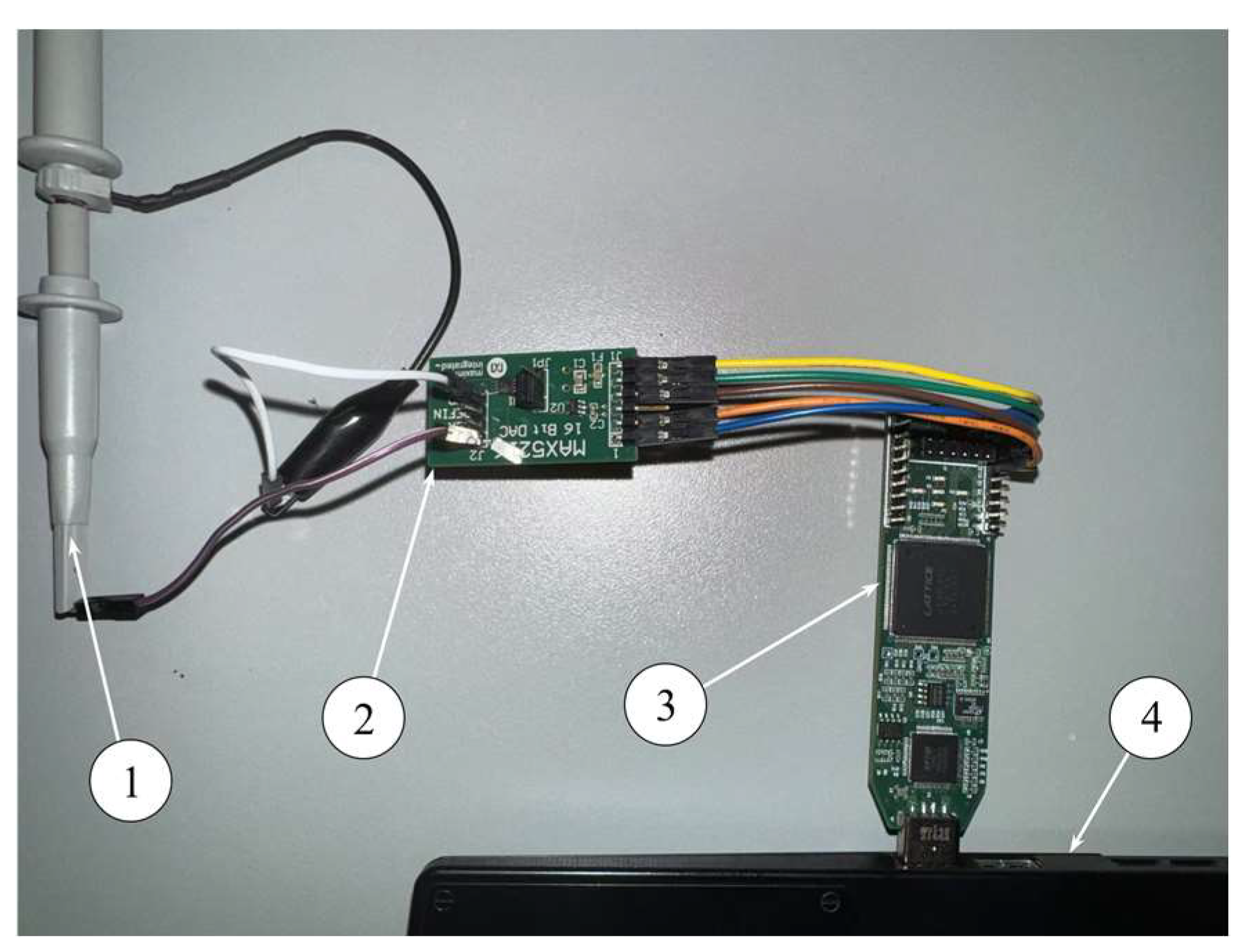
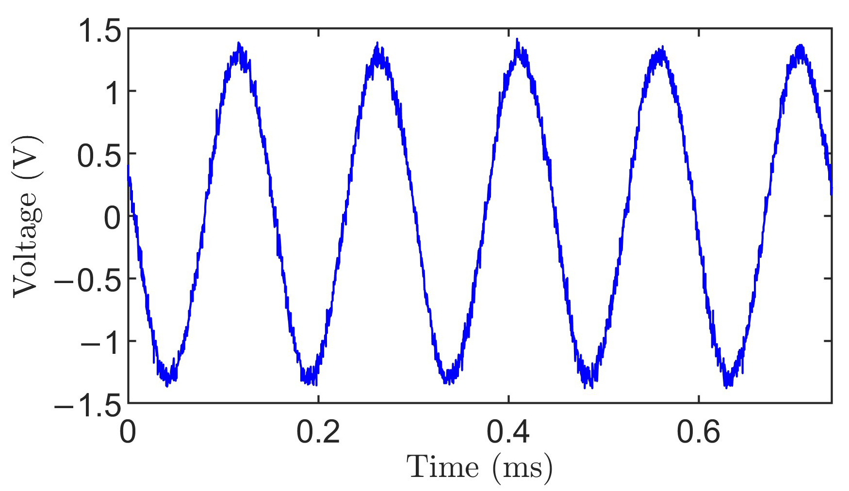
3.2. Experiment Result

The HRT DDFS prototype is then implemented on a Lattice iCE40HX1K FPGA and is evaluated using the experimental configuration shown in Figure 11. Digital outputs from the FPGA are converted to analog signals via a MAX5216 16-bit DAC (Analog Devices Inc., Wilmington, MA, USA), which updates at a sampling frequency of approximately 1.724 MHz (corresponding to 580 ns per output) [23]. Due to system-level timing constraints, the maximum achievable fundamental frequency under this configuration is approximately 6.75 kHz. This upper bound is limited primarily by the DAC update rate rather than the computational latency of the HRT architecture itself.
Figure 12 illustrates the time-domain output generated by the HRT-based DDFS, while Figure 13 shows its corresponding frequency-domain spectrum at a fundamental frequency of 6.75 kHz. The output exhibits a dominant spectral component at the desired frequency, with spurious signals and background noise spread across the Nyquist band. The measured SFDR is −58.86 dBc. This value is primarily constrained by the analog noise floor of the MAX5216 16-bit DAC [23], rather than by the algorithm itself. According to the datasheet [23], the MAX5216 exhibits a typical output noise density of approximately 40 nV/√Hz across a bandwidth of 10 Hz to 100 kHz. When integrated over the test bandwidth (~10 kHz), this corresponds to an RMS voltage noise of approximately 4 μV. Given the DAC’s full-scale output of 3 V, this translates to a theoretical noise floor of −57.5 dBc, which is consistent with the measured spectral floor (−58.86 dBc). Additional analog imperfections, such as thermal noise, reference voltage ripple, and voltage buffer nonidealities, further contribute to spurious content and spectral spreading. Therefore, the observed discrepancy between simulation and experimental SFDR is not attributed to the HRT algorithm itself, but rather to the physical limitations imposed by the DAC hardware used in the test platform.
Table 2 compares signal quality at an output frequency of 6.75 kHz for five DDS algorithms, using SFDR and signal-to-noise ratio (SNR) as evaluation metrics. The CORDIC method yields an SFDR of −51.27 dBc and an SNR of 46.93 dB, limited by quantization and angular rotation errors inherent in its iterative structure. The RT technique shows similar results, with SFDR of −52.07 dBc and SNR of 47.12 dB, due to cumulative error propagation in the absence of resets. Piecewise interpolation achieves a slightly higher SFDR of −52.18 dBc, but its SNR remains at 46.89 dB, as discontinuities at segment boundaries introduce broadband noise. The second-order Taylor method improves both metrics to −57.73 dBc SFDR and 51.03 dB SNR, leveraging smooth polynomial evaluation around fixed centers. The proposed HRT technique achieves the best performance, with −58.86 dBc SFDR and 52.74 dB SNR, due to its periodic Taylor reinitialization and recursive cosine generation. Compared to the other methods, the HRT technique provides the highest SNR, suggesting better noise suppression capabilities. SNR values around 50 dB are generally considered adequate for typical DDS applications such as digital clock generation, embedded waveform synthesis, and actuator control, in which ultra-low-noise performance is not critical [24]. Therefore, HRT not only improves harmonic suppression but also maintains sufficiently low noise for these standard applications.
To further evaluate the influence of cumulative errors under varying recursive depths, Table 3 reports the signal quality of the HRT DDFS across a range of output frequencies. As the frequency decreases from 13.46 kHz to 1.68 kHz, the number of recursive iterations required to complete one waveform period increases from 32 to 256, thereby intensifying the potential for numerical error accumulation. Nevertheless, the SFDR remains relatively stable between −53.92 dBc and −58.86 dBc, and the SNR exhibits a gradual improvement from 50.02 dB to 55.07 dB. These results indicate that the periodic reinitialization in HRT limits iterative error accumulation and preserves signal quality even under extended recursive computation at low output frequencies.
To evaluate the feasibility of the HRT technique on the Lattice ICE40HX1K FPGA, it is also incorporated and tested to examine resource utilization. The resource utilization results are presented in Table 4. When compared with the high-overhead CORDIC implementation, HRT reduces LUT usage by 8.8% and flip-flops by 85.2%, while eliminating the iterative shift–add structure. Relative to the memory-based piecewise interpolation, HRT requires a total of 827 LUTs compared to 131 for LI, which reflects the additional logic required for recursive computation and reset scheduling. However, it avoids dependence on dedicated ROM blocks, which are used in piecewise interpolation (1 block), making HRT more suitable for FPGA platforms with limited memory resources such as the ICE40HX1K. Compared to the second-order Taylor method, HRT adds 33% more LUTs and slightly reduces flip-flop count (−13.9%). When compared with the original RT technique that omits both reset logic and Taylor interpolation, the HRT design shows an 8.2% increase in LUTs (from 764 to 827) and a 6.5% rise in logic cell count (from 802 to 854). In contrast, flip-flop usage is reduced significantly by 59.8% (from 204 to 82), as several pipeline registers in the original recurrence are replaced with combinational control for reset scheduling. These changes primarily result from the additional reset controller and the second-order Taylor operation, which require one coefficient register, a phase comparison unit, and a multiplier–adder pair. Therefore, it can be seen that the inclusion of reset logic and the second-order Taylor block can introduce only marginal increases in LUT usage relative to RT but reduces register count and maintains a ROM-free implementation—an acceptable trade-off in exchange for enhanced SFDR and SNR.
Table 5 summarizes the resource utilization characteristics of several DDFS algorithms, based on analysis of recent literature. The listed methods are presented in order, which offers a comparative overview of architectural requirements under similar implementation conditions.
It is seen from Table 5 that the CORDIC approach consumes 1176 LUTs and 135 arithmetic units, representing a 42.2% increase in LUT usage and more than a 67-fold increase in arithmetic logic compared to the proposed HRT. The piecewise design requires 131 LUTs and 73 flip-flops, corresponding to an 84.2% reduction in LUTs relative to HRT, but it lacks frequency tunability due to fixed segmentation. The Hermite-based method records the highest LUT usage at 1392—approximately 68.2% more than HRT—and incorporates 46 multipliers, making it less suitable for resource-constrained environments. The segmented Taylor design is more efficient in logic utilization, requiring only 328 LUTs (a 60.3% reduction), but relies on fixed precomputed coefficients and does not support dynamic frequency selection. The classical RT implementation utilizes 1009 LUTs and 1142 flip-flops, reflecting an 18.1% increase in LUTs and over a 12-fold increase in flip-flops when compared to HRT, largely due to the absence of a reset mechanism. In contrast, the HRT architecture maintains a balanced hardware profile, with 827 LUTs, 82 flip-flops, and 2 multipliers. Its flip-flop count is 59.9% lower than that of the classical RT design, attributed to the reset-based control structure that can minimize unnecessary pipeline registers. While HRT introduces additional logic for adaptive resets and Taylor interpolation, the associated resource increase is moderate and justified by its spectral performance and implementation flexibility.

4. Conclusions

An HRT technique is proposed in this work for DDFS implementation on low-resource FPGAs. The HRT technique integrates a trigonometric recurrence with periodic second-order Taylor-based reset to suppress cumulative error propagation inherent in classical recursive techniques. Unlike conventional DDFS architectures that rely on large ROM-based waveform tables or complex iterative algorithms such as CORDIC, the HRT design eliminates memory dependence and enables efficient waveform generation through a reset-enhanced recursive scheme. The effectiveness of the proposed HRT technique has been validated through implementation of both simulation and experimental tests on the Lattice iCE40HX1K FPGA. Simulation results indicate that HRT achieves an SFDR of −86.09 dBc and a SNR of 52.74 dB using 16-bit fixed-point arithmetic, approaching the theoretical performance bound of ideal sinusoidal synthesis. Experimental testing further confirms the feasibility of the architecture under practical hardware constraints, yielding a measured SFDR of −58.86 dBc. Comparative analysis with conventional techniques such as CORDIC, piecewise polynomial interpolation, the second-order Taylor, and RT techniques, demonstrates that HRT can provide a favorable trade-off between spectral fidelity and hardware resource usage. Although the proposed HRT technique can effectively mitigate cumulative recursive errors within the evaluated frequency range and fixed-point precision, its experimental spectral performance is primarily limited by the inherent noise floor of the DAC hardware rather than by the algorithm itself. Furthermore, the inclusion of reset logic and Taylor-based interpolation introduces moderate additional hardware resource usage compared to classical RT. Future work will be undertaken to include the implementation of the HRT architecture on higher-speed FPGA and DAC platforms to further evaluate its spectral performance under increased sampling rates and more constrained timing conditions. In addition, further investigation will consider the method’s performance under a broader range of operating conditions, such as reduced bit-width arithmetic and higher output frequencies, where the influence of quantization noise and approximation accuracy may become more pronounced.

Author Contributions

Conceptualization, X.X., W.M. and W.W.; methodology, X.X.; hardware, X.X.; validation, X.X.; formal analysis, X.X.; investigation, X.X.; resources, X.X.; data curation, X.X.; writing—original draft preparation, X.X.; writing—review and editing, W.M., W.W. and X.X.; visualization, X.X.; supervision, W.M. and W.W.; project administration, W.M. and W.W.; funding acquisition, W.M. and W.W. All authors have read and agreed to the published version of the manuscript.

Funding

This work was supported in part by the Natural Sciences and Engineering Research Council of Canada (NSERC) and the Bare Point Water Treatment Plant in Thunder Bay, ON, Canada.

Data Availability Statement

Data are contained within the article.

Conflicts of Interest

The authors declare no conflict of interest.

References

  1. Tierney, J.; Rader, C.; Gold, B. A Digital Frequency Synthesizer. IEEE Trans. Audio Electroacoust. 1971, 19, 48–57. [Google Scholar] [CrossRef]
  2. Asfour, A.; Raoof, K.; Yonnet, J.P. Software Defined Radio (SDR) and Direct Digital Synthesizer (DDS) for NMR/MRI Instruments at Low-Field. Sensors 2013, 13, 16245–16262. [Google Scholar] [CrossRef] [PubMed]
  3. Villalba, J.; Zapata, E.; Antelo, E.; Bruguera, J. Radix-4 Vectoring CORDIC Algorithm and Architectures. J. Signal Process. Syst. 1998, 19, 127–147. [Google Scholar] [CrossRef]
  4. Meher, P.K.; Park, S.Y. Design of Cascaded CORDIC Based on Precise Analysis of Critical Path. Electronics 2019, 8, 382. [Google Scholar] [CrossRef]
  5. Jeng, S.S.; Lin, H.C.; Lin, C.H. A Novel ROM Compression Architecture for DDFS Utilizing the Parabolic Approximation of Equi-Section Division. IEEE Trans. Ultrason. Ferroelectr. Freq. Control 2012, 59, 2603–2612. [Google Scholar] [CrossRef] [PubMed]
  6. Catunda, S.Y.C.; Saavedra, O.R. Constraints definition and evaluation of piecewise polynomial approximation functions for embedded systems. In Proceedings of the IEEE Instrumentation and Measurement Technology Conference, Anchorage, AK, USA, 7 August 2002; Volume 2, pp. 1103–1108. [Google Scholar]
  7. Nochetto, R.H.; Otárola, E.; Salgado, A.J. Piecewise polynomial interpolation in Muckenhoupt weighted Sobolev spaces and applications. Numer. Math. 2016, 132, 85–130. [Google Scholar] [CrossRef]
  8. Changela, A.; Kumar, Y. A Modified Radix-16 CORDIC Algorithm-Based Direct Digital Frequency Synthesizer. In Proceedings of the 2022 5th International Conference on Contemporary Computing and Informatics (IC3I), Uttar Pradesh, India, 14–16 December 2022; pp. 1–6. [Google Scholar]
  9. Palomäki, K.I.; Nurmi, J. Taylor Series Interpolation-Based Direct Digital Frequency Synthesizer with High Memory Compression Ratio. Sensors 2025, 25, 2403. [Google Scholar] [CrossRef] [PubMed]
  10. Lan, J.; Gui, L.; She, W.; Hu, J.; Lang, L.; Huang, Q. Spurious Suppression and Frequency Accuracy Enhancement in Direct Digital Frequency Synthesis: Analysis, Simulation, and Experiment. IEEE Trans. Instrum. Meas. 2025, 74, 6504012. [Google Scholar] [CrossRef]
  11. Wang, C.C.; Sulistiyanto, N.; Shih, H.Y.; Lin, Y.C.; Wang, W. Power-Effective ROM-Less DDFS Design Approach with High SFDR Performance. J. Signal Process. Syst. 2020, 92, 213–224. [Google Scholar] [CrossRef]
  12. Lu, Z.; Zhang, B.; Peng, X.; Liu, H.; Li, X.; Peng, Y.; Xiao, Y.; Zhang, W.; Tang, H. A New Artificial Neural Network-Based Calibration Mechanism for ADCs: A Time-Interleaved ADC Case Study. IEEE Trans. Very Large Scale Integr. (VLSI) Syst. 2024, 32, 1184–1195. [Google Scholar] [CrossRef]
  13. Pomponio, M.; Hati, A.; Nelson, C. Ultra-Low Phase Noise Frequency Division With Array of Direct Digital Synthesizers. IEEE Trans. Instrum. Meas. 2024, 73, 5501310. [Google Scholar] [CrossRef] [PubMed]
  14. Xing, X.; Wang, W. A New Recursive Trigonometric Technique for FPGA-Design Implementation. Sensors 2023, 23, 3683. [Google Scholar] [CrossRef] [PubMed]
  15. Xing, X.; Melek, W.; Wang, W. A Recursive Trigonometric Technique for Direct Digital Frequency Synthesizer Implementation. Electronics 2024, 13, 4762. [Google Scholar] [CrossRef]
  16. Yu, F.; He, S.; Yao, W.; Cai, S.; Xu, Q. Bursting Firings in Memristive Hopfield Neural Network with Image Encryption and Hardware Implementation. IEEE Trans. Comput.-Aided Des. Integr. Circuits Syst. 2025, 1, 1. [Google Scholar] [CrossRef]
  17. Vankka, J. Methods of Mapping from Phase to Sine Amplitude in Direct Digital Synthesis. IEEE Trans. Ultrason. Ferroelectr. Freq. Control 1997, 44, 526–534. [Google Scholar] [CrossRef] [PubMed]
  18. Korn, G.A.; Korn, T.M. Functions and Limits. Differential and Integral Calculus. In Mathematical Handbook for Scientists and Engineers, 2nd ed.; Dover Publications: New York, NY, USA, 2000; Chapter 4; pp. 132–134. [Google Scholar]
  19. Stegun, I.; Abramowitz, M. Handbook of Mathematical Functions with Formulas, Graphs, and Mathematical Tables; National Bureau of Standards, Applied Mathematics Series 55; Abramowitz, M., Stegun, I.A., Eds.; Dover Publications: New York, NY, USA, 1972. [Google Scholar]
  20. Huang, Z.; Zhang, S.; Wang, W. An Efficient Method of Parallel Multiplication on a Single DSP Slice for Embedded FPGAs. IEEE Access 2019, 7, 99947–99956. [Google Scholar] [CrossRef]
  21. Alink, M.S.O.; Kokkelcor, A.B.J.; Klumperink, E.A.M.; Rovers, K.C.; Smit, G.J.M.; Nauta, B. Spurious-Free Dynamic Range of a Uniform Quantizer. IEEE Trans. Circuits Syst. II Express Briefs 2019, 66, 1006–1010. [Google Scholar]
  22. Guo, X.; Wu, D.; Zhou, L.; Liu, H.; Wu, J.; Liu, X. High speed high resolution direct digital frequency synthesizer with non-linear DAC coarse quantization and ROM-based piecewise linear interpolation. Analog Integr. Circ. Sig. Process. 2017, 90, 263–272. [Google Scholar] [CrossRef]
  23. Maxim Integrated. 14-/16-Bit, Low-Power, Buffered Output, Rail-to-Rail DACs with SPI Interface. MAX5216 Datasheet, September 2010; Revised June 2013. Available online: https://www.analog.com/media/en/technical-documentation/data-sheets/MAX5214-MAX5216.pdf (accessed on 26 July 2025).
  24. Man, P.; Ding, C.; Ren, W.; Xu, G. A Nonlinear Fingerprint-Level Radar Simulation Modeling Method for Specific Emitter Identification. Electronics 2021, 10, 1030. [Google Scholar] [CrossRef]
  25. Zhou, K.; Xu, Q.; Zhang, T. Optimized Design of Direct Digital Frequency Synthesizer Based on Hermite Interpolation. Sensors 2024, 24, 6285. [Google Scholar] [CrossRef]
Figure 1. Cumulative error of the RT technique (16-bit fixed-point).
Electronics 14 03027 g001
Figure 2. Cumulative error comparison of RT and HRT (16-bit fixed-point).
Electronics 14 03027 g002
Figure 3. Cumulative error comparison of RT and 2nd-Order Taylor polynomial (16-bit fixed-point).
Electronics 14 03027 g003
Figure 4. Cumulative error comparison of 2nd-Order Taylor polynomial and HRT technique with (a) 2, (b) 4, (c) 8, and (d) 16 resets points at 0° to 30° (16-bit fixed-point).
Electronics 14 03027 g004
Figure 5. Cumulative error comparison of 2nd-order Taylor polynomial and HRT technique with (a) 2, (b) 4, (c) 8, and (d) 16 resets points at 30° to 60° (16-bit fixed-point).
Electronics 14 03027 g005
Figure 6. Cumulative error comparison of 2nd-Order Taylor polynomial and HRT technique with (a) 2, (b) 4, (c) 8, and (d) 16 resets points at 60° to 90° (16-bit fixed-point).
Electronics 14 03027 g006
Figure 7. Cumulative error comparison of RT, 2nd-Order Taylor polynomial, and HRT (16-bit fixed-point).
Electronics 14 03027 g007
Figure 8. The architecture of the proposed HRT technique.
Electronics 14 03027 g008
Figure 9. The reset control logic in the proposed HRT architecture.
Electronics 14 03027 g009
Figure 10. Spurious performance of the HRT cosine output at 0.695 MHz (fs = 50 MHz), with the dashed line indicating an SFDR level of −86.09 dBc.
Electronics 14 03027 g010
Figure 11. Experiment setup of proposed DDFS: (1) Oscilloscope; (2) DAC module; (3) Lattice ICE40 FPGA module; (4) PC.
Electronics 14 03027 g011
Figure 12. Time-domain output from the HRT based DDFS.
Electronics 14 03027 g012
Figure 13. Spectrum output from the HRT based DDFS at 6.75 kHz.
Electronics 14 03027 g013
Table 1. Comparison of SFDR using the related algorithms under ModelSim.
Algorithm16-Bit Cosine SFDR (dBc)
CORDIC−42.45
Piecewise−53.02
2nd Taylor−82.02
RT−52.31
HRT−86.09
Table 2. Comparison of the signal quality using the related algorithms.
AlgorithmSFDR (dBc)SNR (dB)
CORDIC−51.2746.02
Piecewise−52.1846.98
2nd Taylor−57.7351.03
RT−52.7147.13
HRT−58.8652.74
Table 3. Comparison of the signal quality of the HRT technique with different frequency.
Frequency (kHz)IterationsSFDR (dBc)SNR (dB)
13.4632−53.9250.02
6.7364−58.8652.72
3.37128−58.5153.91
1.68256−57.8055.07
Table 4. Comparison of the resource utilization using the related algorithms.
AlgorithmLUTsFlip FlopsROMs
CORDIC9075550
Piecewise131731
2nd Taylor620720
RT7642040
HRT827820
Table 5. Comparison of the resource utilization between proposed architecture to other recent state-of-the-art approaches.
AlgorithmLUTsFlip FlopsAritect. Blocks
CORDIC [8]1176N/A135
Piecewise [22]1317327
Hermite [25]1392N/A46 multipliers
Taylor seg [9]3282243 DSPs
RT [15]100911421 multiplier
Proposed827822 multipliers
Disclaimer/Publisher’s Note: The statements, opinions and data contained in all publications are solely those of the individual author(s) and contributor(s) and not of MDPI and/or the editor(s). MDPI and/or the editor(s) disclaim responsibility for any injury to people or property resulting from any ideas, methods, instructions or products referred to in the content.

