Article

Brush Stroke-Based Writing Trajectory Control Model for Robotic Chinese Calligraphy

1
School of Computer Science and Engineering, Anhui University of Science and Technology, 168 Taifung Street, Tian Jiaan District, Huainan 232001, China
2
State Key Laboratory of Digital Intelligent Technology for Unmanned Coal Mining, Anhui University of Science and Technology, Huainan 232001, China
*
Author to whom correspondence should be addressed.
Electronics 2025, 14(15), 3000; https://doi.org/10.3390/electronics14153000
Submission received: 26 June 2025 / Revised: 16 July 2025 / Accepted: 22 July 2025 / Published: 28 July 2025

Abstract

Engineering innovations play a critical role in achieving the United Nations’ Sustainable Development Goals, especially in human–robotic interaction and precise engineering. For the robot, writing Chinese calligraphy with hairy brush pen is a form of precision operation. Existing writing trajectory control models mainly focus on writing trajectory models, and the fine-grained trajectory control model based on brush strokes is not studied. The problem of how to establish writing trajectory control based on brush stroke model needs to be solved. On the basis of the proposed composite-curve-dilation brush stroke model (CCD-BSM), this study investigates the control methods of intelligent calligraphy robots and proposed fine-grained writing trajectory control models that conform to the rules of brush calligraphy to reflect the local writing characteristics. By decomposing and refining each writing process, control models in the process of brush movement are analyzed and modeled. According to the writing rules, fine-grained writing trajectory control models of strokes are established based on the CCD-BSM. The parametric representations of the control models are built for the three stages of initiation, execution, and completion of strokes writing. Experimental results demonstrate that the proposed fine-grained control models can exhibit excellent performances in basic strokes and Chinese characters with better writing capabilities. Compared with existing models, the writing results demonstrate the advantages of our proposed model in terms of high average similarity with two quantitative indicators Cosine similarity (CSIM) and Structural similarity index measure (SSIM), which are 99.54% and 97.57%, respectively.

1. Introduction

Engineering innovations in today’s world, especially technologies in human–robotic interaction and precise engineering, are pivotal in achieving the United Nations Sustainable Development Goals. Writing Chinese calligraphy with a hairy brush pen by an intelligent robot is a form of precision operation. Writing trajectory control model, as a crucial component in intelligent robotic calligraphy, plays an important role in the rendering effect of robotic calligraphy works [1,2,3,4]. Unlike soft robotic system [5] and existing intelligent writing robots that use hard pens [6,7], the use of a hairy brush pen requires the consideration of the brush stroke model, that is, the brush pen with a certain pressing height and inclined angle on the paper to form a special graphic [8].
To understand the significance of the results, we explain the meaning of specialized terms based on the writing process of calligraphic:
Bifeng: The tip of the hairy brush pen.
Yunbi: The writing process in which a stroke is written.
Qibi: The beginning of writing a stroke.
Shoubi: The ending of writing a stroke.
Xingbi: The hairy brush pen moves horizontally with a certain pressing height and inclined angle.
zhongfengxingbi: The brush tip remains in the center of the stroke at all times.
cefengxingbi: The brush tip deviates from the centerline of the stroke.
Most of the existing control models used traditional B-splines for trajectory interpolation. Wen Y et al. [9] proposed a robotic trajectory tracking control method, using cubic spline interpolation to generate a closed geometric three-dimensional path. The three-dimensional kinematic model of the end-effector was established to control the input velocity and tangent vector of the trajectory path. By transforming the writing problem into an optimization problem, Zhenyu X et al. [10] studied a method to minimize the input energy of the writing trajectory by modeling characters. With normalized uniform B-splines as basic functions, skeleton images of characters were generated from trajectories. The single-pixel characters were then transformed into corresponding written characters based on the pix2pix image transformation framework using deep learning. However, employing B-spline interpolation for writing control cannot comprehensively reflect the local writing characteristics of strokes or Chinese characters, resulting in significant discrepancies between the generated models and actual characters.
Recently, the machine learning-based approach [11], deep reinforcement learning and generative adversarial networks [12,13,14,15,16,17,18,19] have been used to predict flow status and to train robots for writing tasks widely. Generative adversarial networks—actor–critic (GAN-AC) [14] integrated deep reinforcement learning with generative adversarial network. During learning and training, the actor–critic (AC) algorithm was used to control the robot to write repeatedly and generate images multiple times. However, extensive repeated writing operations will inevitably lead to a rapid decline and exhaustion for the service life of the robot. Moreover, the common problem of these models is the lack of a brush stroke model, as they merely trained the robot to write strokes repeatedly without conforming to the three-stage principle of calligraphy writing named “qibi”, “xingbi” and “shoubi” (initiation, execution and completion of strokes).
To solve the above problems, a previously proposed brush stroke model named CCD-BSM [20] is indispensable. CCD-BSM is a closed composite curve dilation brush stroke model, which was designed with an oblique section of a cone and two tangent parabolas and can be fixed through analytical geometric calculation. Then, a basic stroke graphic can be generated based on the designed composite curve [20]. In the proposed model, only four measurable and controllable parameters were defined, including the length of a hairy brush bundle, maximum radius of a brush bundle, depth to which the pen was pressed, and inclined angle between the pen and vertical direction when touching the paper. All parameters of the CCD-BSM are determined according to the specification and posture of the hairy brush pen with rigorous mathematical proof, without manual setting by experience or parameter estimation on a number of samples [20]. Compared with existing dynamic brush models, CCD-BSM leads to good generalization and robustness for different pens as the specifications of brush pens are taken into consideration. The writing trajectory is composed of several trajectory points by our CCD-BSM. It is defined by the specification of the hairy brush pen, pressed depth (H), inclined angle (α) and rotation angle (θ). We have provided the mathematical relationship between H, α, θ and the brush stroke model CCD-BSM of the trajectory [20].
Based on the existing CCD-BSM, this paper studies the writing trajectory control model of calligraphy robots and proposed a fine-grained modeling method to reflect the local writing characteristics. By decomposing and refining each writing process of brush, the commonly used control models for “xingbi”, “zhuanbitiaofeng” and “zhebi” are analyzed and built. Based on these different “yunbi” control methods, the trajectory control model based on the CCD-BSM is established; furthermore, the trajectory control model for single strokes can be developed. According to the writing rules of brush, the corresponding description and representation of the three steps of “qibi”, “xingbi” and “shoubi” are given. The experimental results demonstrate that the proposed fine-grained trajectory control model exhibited excellent performance in both basic strokes and Chinese characters. The trajectory control process and the robotic writing effects are illustrated in Figure 1. By modeling different control methods of “yunbi”, the fine-grained control models based on the brush stroke model are proposed, along with three-stage control models conforming to calligraphy rules. Moreover, writing tests and performance evaluations were carried out to verify the performance of our proposed control model. Compared to most existing models, it holds significant advantages with good generalization and robustness.
The main contributions of this study are summarized as follows:
  • By decomposing and refining each writing process, the commonly used control methods and models for “xingbi”, “zhuanbitiaofeng” and “zhebi” are analyzed and built.
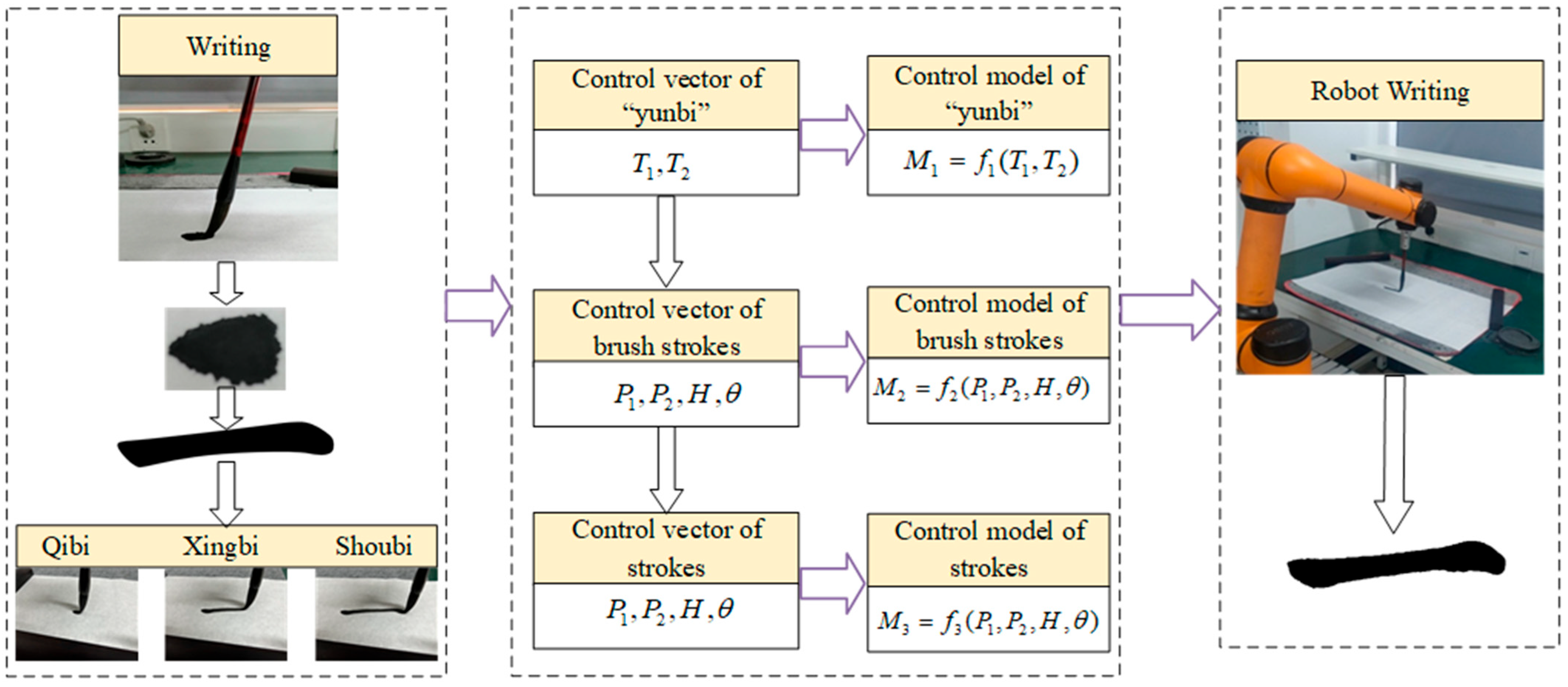
  • Based on the existing CCD-BSM, the writing trajectory control models and methods of calligraphy robots are studied and established. According to the writing rules of brush, the corresponding description and representation of the three steps of “qibi”, “yunbi” and “shoubi” are given.
  • The fine-grained writing trajectory control models that adhere to the rules of brush calligraphy are proposed. The experimental results show that compared with other models the proposed model has better performance in both basic strokes and Chinese characters with good generalization and robustness.

2. Related Works

  • Based on Bézier curve and B-Spline curve
The traditional cubic B-spline algorithm [21,22,23] has been widely used to plan Cartesian space paths, optimize the trajectory and control robot writing. Mueller S et al. [24] established a 6-DOF robotic writing system based on KUKA. Based on the B-Spline curve, basic strokes were trained. B-splines of reference strokes and actual contours written by robots were obtained. The visual feedback mechanism was utilized in the learning process to calculate the error between the reference characters and the drawing characters; then, the trajectory was updated to generate a training function. But the writing system can only reproduce simple strokes in the database. Lin H I et al. [25] proposed a trajectory model to provide three-dimensional coordinates for robot control. Berio D et al. [26] used a spline-based method to edit polygon and synthesize a continuous virtual trajectory.
2.
Based on learning control and optimal control
Wu R et al. [27] proposed a robot writing framework based on a robotic hand–eye coordination method. Berio et al. [28,29] proposed methods for generating interactive curves and paths. The stochastic formulas of optimal control theory were used to calculate variations in dynamic systems. Huebel N et al. [30] calculated the error between reference characters and drawn characters based on the projected positions to form the paper coordinate position of the robot’s writing trajectory. They used a P-type iterative learning controller (ILC) by a learning node to obtain the Z-axis coordinate position and eventually generate the three-dimensional coordinates ( x , y , z ) as the robot’s trajectory. Inspired by the pseudo-spectral optimal control, Wang S et al. [31] parameterized the execution trajectory of each stroke as Chebyshev polynomials and applied the pseudo-spectral optimal control (PSOC) method to optimize the open-loop control trajectory of the robotic end-effector.
Mueller S et al. [24] proposed a vision feedback-based iterative optimization writing method, but its iterative optimization process is computationally complex and time-consuming. They compared the writing results with reference strokes to evaluate and update the writing trajectory. Based on error data points and previous splines, the positions of control point for the next iteration were determined to update the contours of strokes.
Ma Z et al. [32] established a closed-loop calligraphy system to reduce errors and perform aesthetic optimization. By predicting the position of the n + 1th stroke based on the positions of the first n strokes, they controlled the writing strategy of the robotic calligraphy. A constrained optimization problem was defined to optimize the aesthetic evaluation and control the writing trajectory of each stroke by the robot.
3.
Based on deep learning
The Long short-term memory network—generative adversarial network (LSTM-GAN) [12] enabled the robot to learn and generate sequences of Chinese character strokes, namely, writing trajectories, and optimize these trajectories based on the writing results. In the absence of a dataset of the robot’s motion trajectories, the combined LSTM-GAN network structure can convert pixel-level stroke images into vector trajectory sequences for robot control. Zhou P et al. [17] extracted parameters of character images with the target style, then converted them into control parameters to guide the writing process and generate writing trajectory precisely.
In summary, existing robotic writing trajectory control methods for robotic Chinese calligraphy are mainly based on a Bézier curve and B-Spline curve, learning control and optimal control and deep learning. However, these models and methods lack the fine-grained modeling method, generalization and the brush stroke model to reflect the local writing characteristics and artistic presentation. As a basic unit of strokes and characters, the brush stroke model should be considered in the trajectory control model. Thus, the fine-grained modeling method that combines the writing rules of the hairy brush pen and the brush stroke model with good generalization and robustness needs to be addressed urgently.

3. Methods and Models

The construction of control methods and models are required based on the CCD-BSM brush stroke model during the “yunbi” process. Then, on this basis, the writing trajectory can be obtained for robotic brush calligraphy by combining different methods of “yunbi”.

3.1. Control Method of “Yunbi”

During the writing process, the influence factors of “yunbi” control methods mainly include the drop height, tip lag of brush pen and the deviation of the direction angle of brush tip. Among them, the drop height depends on lifting and pressing operations in the vertical direction. The tip lag is mainly determined by the bending of the brush hairs. The deviation angle of the brush tip is jointly determined by the rotation of the brush handle around its own axis, combined with the movement of the handle on the paper. The writing trajectory control models based on the brush stroke model are composed of different control methods. First, the control models for “xingbi”, “zhuanbitiaofeng” and “zhebi” are studied, and then the control models of strokes and Chinese characters are further investigated.

3.1.1. Control Model for “Xingbi”

During the “xingbi” process, the pressing height of the brush pen is set to H and the inclined angle is α . The brush tip moved at a constant speed along the trajectory on the paper, and the writing path can be approximated as a straight line from point T1 to point T2. At this point, the brush handle lagged behind the brush tip, and the trajectory on the paper is from T 1 to T 2 . The direction of the brush tip is opposite to the direction of “yunbi”, moving along T 2 T 1 , as show in Figure 2.
Let the position of the brush tip P be a point on the straight line T 1 T 2 , and the corresponding position of the brush handle be P . At this point, the stroke width is w p . The pressing height and inclined angle of the brush pen are H and α , respectively. The control model shown in Equations (1)–(3) can be denoted as follows.
T 1 T 1 = T 2 T 2 = d
P P = d T 1 T 2 / T 1 T 2
w ( H , α ) = w p

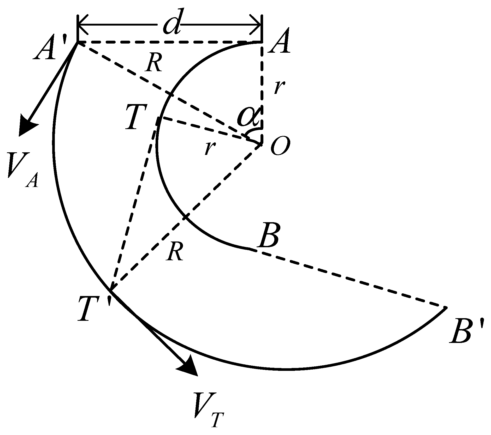
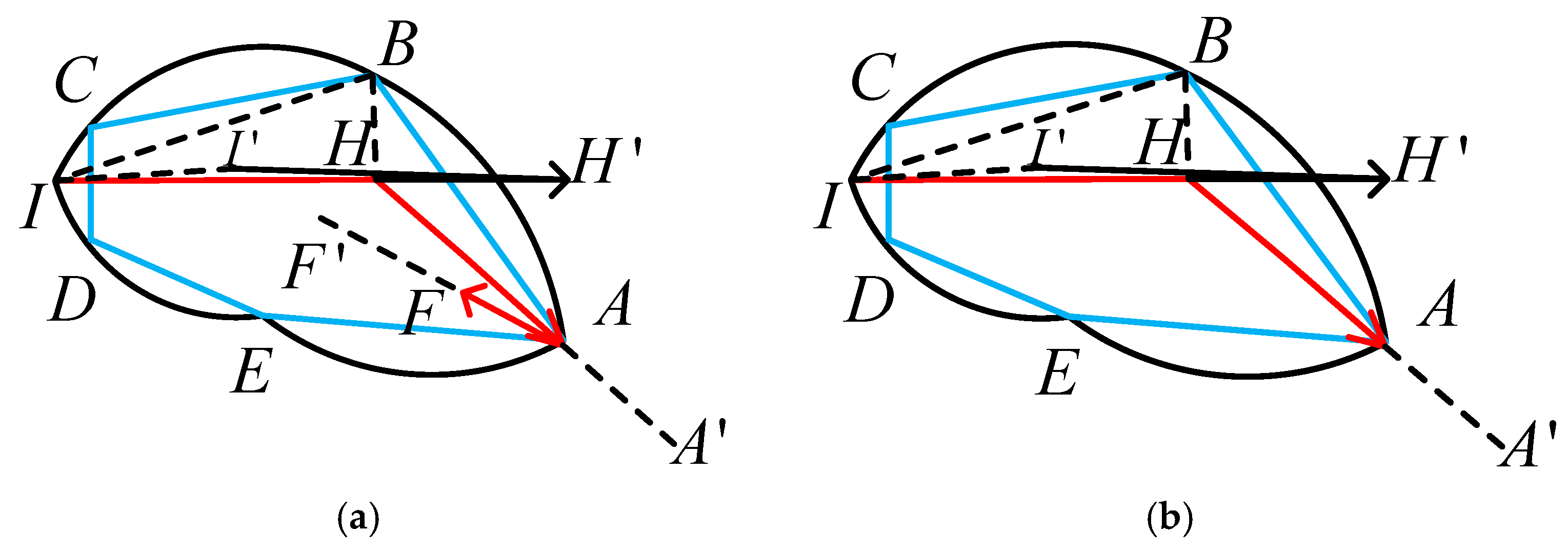
3.1.2. Control Model for “Zhuanbitiaofeng”

The “zhuanbitiaofeng” in brush calligraphy can be viewed as an arc motion on the paper, equivalent to the brush pen being pressed onto a disk with a certain pressing height H and inclined angle α . The brush remains stationary, while the disk rotates counterclockwise continuously. After a time interval T , it will reach a stable state. The brush handle rotates around its own axis, and the brush rotates around the central axis of the disk with the circular motion. Its rotational speed is equal to the speed of the brush handle’s self-rotation. Due to the brush tip lagging behind the brush handle during the rotation, the brush bundle generates concentric arcs as trajectories on the horizontal surface. The writing trajectory as shown in Figure 3 is generated by the brush pen during the process of “zhuanbitiaofeng”. Taking the center of the concentric arcs as the origin of the reference coordinate system, the radius of the inner and outer arcs are set as r and R, respectively.
During the “zhuanbitiaofeng”, when the brush tip moved to position A, the brush handle is located at position A , and the distance between them is d. To obtain an arc with radius r , the brush handle must lie on the extension line of the brush tip trajectory and maintain a constant offset of d from the brush tip. According to geometric calculations, when the brush tip moves to the trajectory point T with parameters H and α , the brush handle is always in the tangent direction of the concentric arc; the relationship is shown in Equation (4).
O T T T
where O T = r , T T = d .
At this time, the brush handle takes A as the starting point of the writing trajectory and moves in a circular arc with radius O T . Compared to the brush tip, its initial direction angle leads ahead of the brush tip by α . The solutions for O T and α are given by Equations (5) and (6), respectively.
O T = r 2 + d 2
α = tan 1 ( d / r )
From the above analysis, the width of the concentric arc is set as w o and the rotation angle of the brush handle is θ r . For any point T on the concentric arc AB, when the brush tip moves from point A to point T along the writing trajectory, the brush handle rotates from point A to point T . The control model can be yielded as shown in Equations (7)–(10).
w ( H , α ) = w o
O T = r 2 + d 2
A O T = A O T + θ
θ r = A O T
where θ = α .

3.1.3. Control Model for “Zhebi”

Unlike “xingbi” and “zhuanbi”, “zhebi” involves the brush tip being pressed onto the paper with a certain pressing height (H) and inclined angle (α). As the parameters were controllable, we used Aubo-I5 script programming to set different combinations of the parameters; then, the end-effector of robotic arm can be adjusted to the parameters with certain H and α. After following a straight trajectory to a specific point, the writing direction is changed, and the brush pen then proceeds to the next point along either a straight or curved trajectory.
Assume the writing trajectory of “yunbi” consists of a curve segment formed by four trajectory points T 1 T 2 T 3 T 4 , where T 1 T 2 and T 3 T 4 are straight segments. The radius of the arc T 2 T 3 is r , and the central angle is T 2 O T 3 . T 1 T 2 and T 3 T 4 are tangent to the arc T 2 T 3 at points T 2 and T 3 , respectively, as shown in Figure 4a. Through the writing method of “zhebi”, it can be seen that when the brush tip moves from point T 1 to point T 2 , it does not follow the original arc trajectory at point T 2 , as in Figure 4a, but instead it moves toward the upper right along T 2 T 4 , resulting in a polyline writing trajectory T 1 T 2 T 4 , as shown in Figure 4b. At this point, the arc segment T 2 T 3 becomes a straight line T 2 T 3 with radius r = 0 . The writing path of the brush handle is a curved segment T 1 T 2 T 3 T 4 , composed of two straight lines T 1 T 2 , T 3 T 4 , and an arc segment T 2 T 3 . T 2 T 3 takes T 2 T 2 as the radius and T 2 as the center. The relationship is shown in Equation (11).
T 2 T 2 = T 2 T 3 = T 4 T 4 = d
In summary, when the “bifeng” reaches point T 2 along T 1 T 2 , the brush handle turns to the upper right and writes along the arc segment T 2 T 3 . Assuming that the pressing height and inclined angle of the brush pen remain unchanged during this process, it continues writing along T 3 T 4 after reaching point T 3 . The control model for the “zhebi” method of brush tip at point T 2 is shown in Equations (12) and (13).
T 2 T 3 = d T 2 T 4 / T 2 T 4
θ r = T 1 T 2 , T 2 T 4
where θ r represents the rotational angle of the brush handle around the axis of rotation.

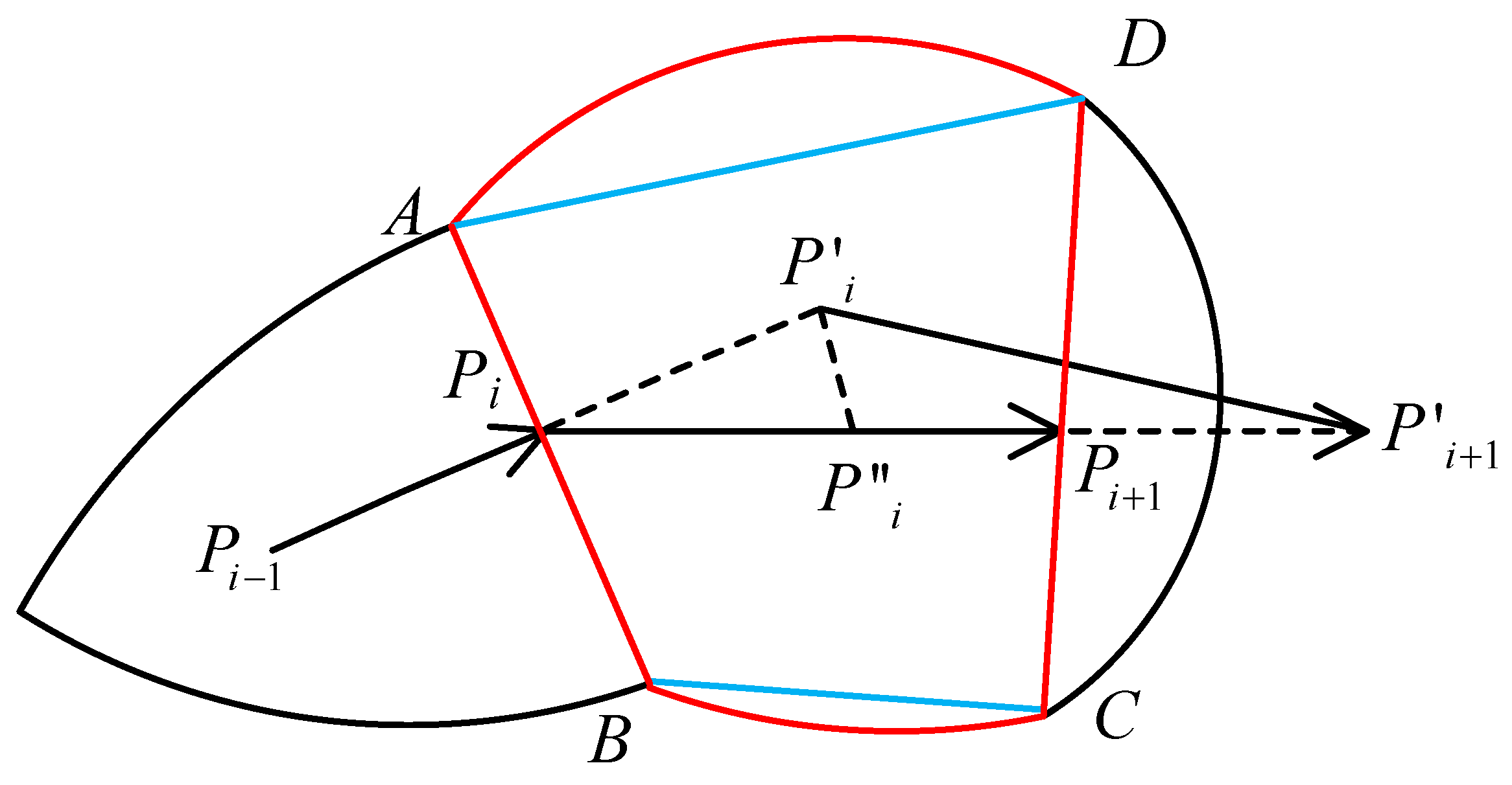
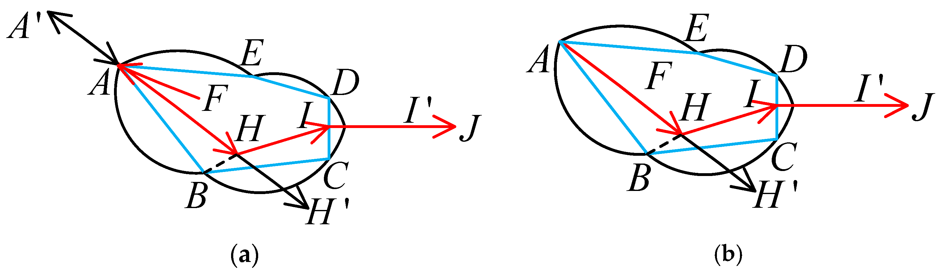
3.2. Control Method of the Brush Stroke Model

The writing models of different control methods at given points have been deduced above. However, to generate the control model of strokes, the trajectory control model based on the brush stroke model is needed. Assuming the trajectory points are P i 1 P i P i + 1 in sequence, the vector of the brush stroke model CCD-BSM is shown in Equation (14), and its control model is illustrated in Figure 5.
σ = ( P i P i + 1 , w i , Δ w i , θ i , Δ θ i )
w i = A B
Δ w i = C D A B
θ i = P i 1 P i , P i P i + 1
Δ θ i = P i 1 P i , P i + 1 P i + 1
where P i and P i + 1 represent the midpoints of A B and C D , respectively. w i and Δ w i indicate the width of the stroke and the change in width, respectively. P i 1 P i A B , P i + 1 P i + 1 C D . The input angle and the rotation angle of the brush tip are represented by θ i and Δ θ , respectively.
As shown in Figure 5, the graphic formed on the paper along the writing trajectory P i P i + 1 is the ABCD portion of the brush stroke model (the region enclosed by red straight and curved lines), where P i and P i + 1 represent the midpoints of AB and CD, respectively, and P i and P i + 1 lie on the extensions of P i 1 P i and P i P i + 1 . The writing process of this brush stroke model is considered as the brush tip performing a transition to the lower right at point P i , making P i P i + 1 the new writing direction. After writing along P i P i + 1 to P i + 1 , the brush tip transitions again to the lower right, and writes along the direction of P i + 1 P i + 1 .
When the brush tip moves to P i along the trajectory P i 1 P i , the brush handle is located at point P i . As the brush moves along P i P i , the brush tip rotates by θ r according to Equation (19). The brush handle then proceeds from P i to P i + 1 along P i P i + 1 with a constant descending height and tilt angle, satisfying the relationship described by Equation (20). As the width of the stroke transitions from AB to CD due to the “zhebi”, the brush handle continues its movement along path P i + 1 P i + 1 until reaching the point P i + 1 , with the rotation angle of the brush handle θ r shown in Equation (21).
θ r = P i P i , P i P i + 1
P i P i + 1 = P i P i + 1
θ r = P i + 1 P i + 1 , P i + 1 P i + 1
where θ r and θ r represent the rotation angles of the brush tip and brush handle, respectively.
The complete writing process is the superposition of the aforementioned three segments. In the extremely small case of P i P i + 1 , the three segments can be treated as one segment. Consequently, the control of the brush handle can be simplified as moving the brush handle directly from P i to P i + 1 along P i P i + 1 , as illustrated in Figure 5. The control relationship can be derived as shown in Equation (22).
P i P i + 1 = P i P i + 1 + P i + 1 P i + 1 d P i 1 P i / P i 1 P i
θ r = P i 1 P i , P i + 1 P i + 1
Δ H = w 1 C D w 1 A B
where θ r represents the rotation angle of the brush handle, and Δ H denotes the variation in the descending height of the brush.
The control vector based on the brush stroke model is defined as shown in Equation (25). Thus, the brush movement corresponding to Figure 5 can be derived as expressed in Equation (26).
M = v , Δ H , Δ θ
where v represents the vector of the brush handle on the paper plane based on CCD-BSM, and Δ H represents the variation in the descending height of the brush. Δ θ denotes the rotation angle of the brush handle.
M i = P i P i + 1 , w 1 C D w 1 A B , P i 1 P i , P i + 1 P i + 1

3.3. Writing Trajectory Control Models of Strokes

Based on the brush stroke model, the stroke width of the writing trajectory is determined by both the parameters of the CCD-BSM and the writing trajectory control model during the actual writing process.

3.3.1. Control Model During the Phase of Stroke Execution

The writing trajectory control of the brush stroke model during this phase is shown in Figure 6, with the vector representation described by Equation (27).
σ i = P i P i + 1 , w i , w i + 1 w i , P i 1 P i , P i P i + 1 , P i 1 P i , P i P i + 1
By substituting Equations (29)–(31), the writing trajectory control parameters can be obtained. Thus, the control sequence for the phase of “xingbi” can be derived as shown in Equation (28).
M i = P i P i + 1 , Δ H i , Δ θ i
P i P i + 1 = P i P i + 1 d P i 1 P i / P i 1 P i
Δ θ i = θ r = P i 1 P i , P i + 1 P i + 1
Δ H i = w 1 C D w 1 A B
where Δ H i denotes the variation in the descending height of the brush. Δ θ i represents the rotation angle of the brush handle.

3.3.2. Control Model During the Phase of Stroke Initiation

The stroke initiation phase is typically composed of multiple brush stroke models, corresponding to multiple writing units. Based on the different writing methods, the motion of the “nifengrubi” of the brush handle is formed by the combinations of σ F A , σ A , σ A H and σ H I , while the motion of the “shunfengrubi” of the brush handle is composed of the combinations of σ A , σ A H and σ H I , as shown in Figure 7. The points A and H are taken on the extensions of lines FA and AH, respectively, such that A A = H H = d ; I J C D . Additionally, the point I is taken on line IJ, such that I I = d .
  • “Nifengrubi”
“Nifengrubi” can be considered as the superposition of two linear brush movements, FA and AH. In the first segment, the brush handle moves from the initial position point F along the straight line FA to point A , while the descending height of the brush gradually increases. The corresponding vectors are described in Equations (32) and (33), respectively.
σ F A = F A , 0 , w min , 0 , 0
M F A = F A , Δ h F A , 0
Due to the characteristics of the “nifengrubi”, in the second segment, the brush handle moves from point A back to A, and the descending height of the brush decreases from w min to 0. The corresponding vectors for this segment are described in Equations (34) and (35), respectively.
σ A = δ A , w min , w min , 0 , 0
M A A = A A , Δ h F A , 0
A A = d F A / F A
F A = F A + A A
where δ A represents the direction vector of I H , and δ A 0 .
2.
“Shunfengrubi” forward-tip entry
In the case of “Shunfengrubi”, the brush tip starts directly from point A, omitting the first two stages of the reverse tip entry.

3.3.3. Control Model During the Phase of Stroke Termination

The stage of the stroke termination is also typically composed of multiple brush stroke models, corresponding to several brush stroke units. Based on the analysis of the brush stroke movement during the stage of stroke termination, the movement of the brush handle is composed of the combination of σ I H , σ H A and σ A F . Figure 8 illustrates the brush movements during the stage of “shoubi” termination. Take points H , A and F on the IH extension line, HA extension line and AF extension line, respectively, so that H H = A A = F F = d ; I I connects to the brush stroke movements of the stroke execution phase, and I I = d .
Similar to the stroke initiation phase, the control of the brush handle during the stroke termination phase mainly includes two different methods: “changfengshoubi” and “loufengshoubi”—hidden-tip termination and exposed-tip termination.
  • “Changfengshoubi”—Hidden-Tip Termination
In hidden-tip termination, the “bifeng” (the brush tip) moves from point A to point F, while the brush handle moves from point A to point F . Simultaneously, the brush is gradually lifted, and at point F , the tip of the brush pen is just above the paper surface. The corresponding brush stroke model vector σ A F and brush movement M A F are described in Equations (38) and (39), respectively.
σ A F = A F , w min , w min , 0 , 0
M A F = A F , h min , 0
A F = A F A A
A F = A F + F F
F F = d A F / A F
where w min can be derived from the descending height h min of the brush pen (based on CCD-BSM stroke model).
2.
“Loufengshoubi”—Exposed-Tip Termination
In the “loufengshoubi”, the brush tip directly leaves the paper surface from point A, skipping the latter two stages of hidden-tip termination.

4. Experimental Results and Discussion

4.1. Experimental Hardware System

In this system, we used Aubo-I5 script programming. Based on a high-precision robotic writing system, a collaborative 6-DOF robot “Aubo-I5” with repeatability of ±0.05 mm was adopted. The writing results were collected using the robotic writing system and a normal camera. The configuration of our experimental hardware system is shown in Figure 9. The AUBO-I5 robot is a rotationally articulated robot that satisfies the composite Pieper criterion, and the parameters corresponding to each joint angle can be obtained by using a hybrid closed solution that satisfies the Pieper criterion. Based on the robotic manipulator maps, the robot’s movement can be controlled to complete the writing operation.
In the experiment, two pens with different specifications were used and affixed to the end-effector of the robot during a writing test. The length and the radius of the brush bundle of pen 1 were 48 mm and 6 mm, respectively, while the length and the radius of the brush bundle of pen 2 were 32 mm and 4.5 mm, respectively.

4.2. Robot Writing Test

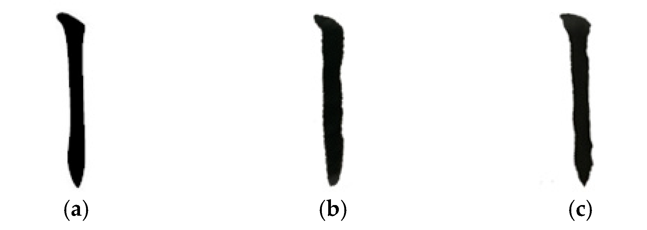
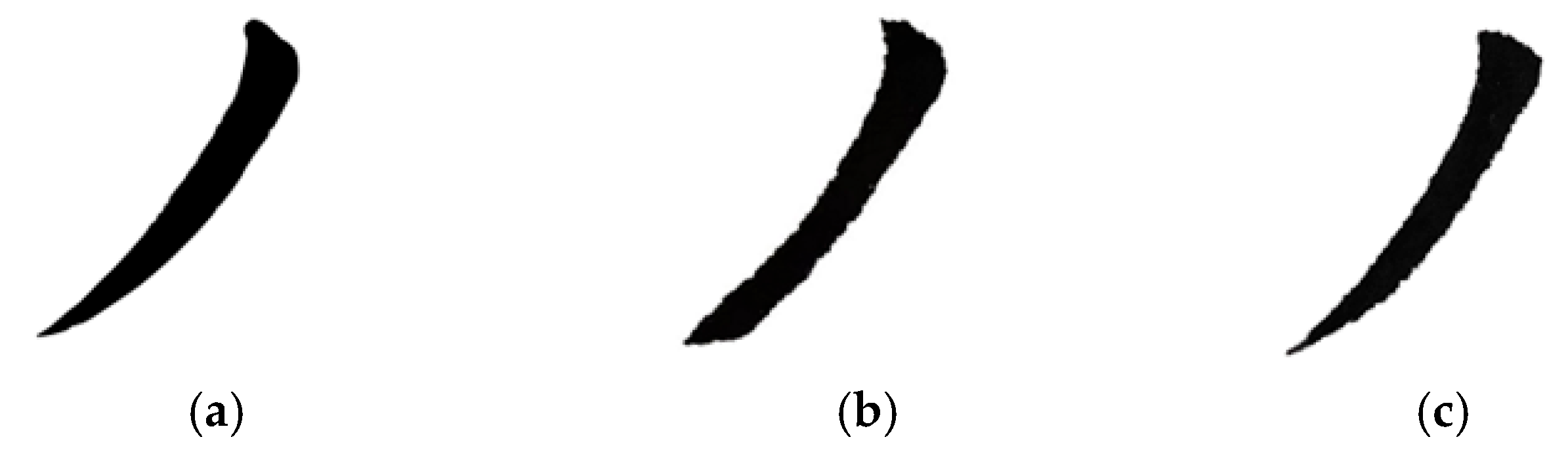
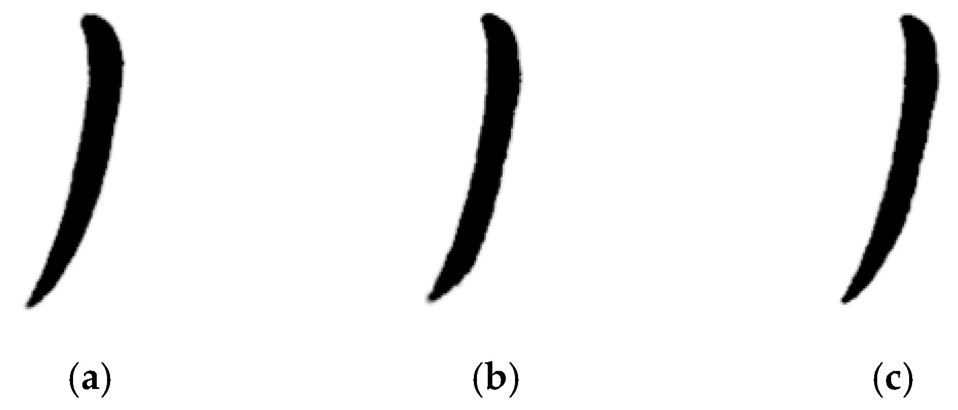
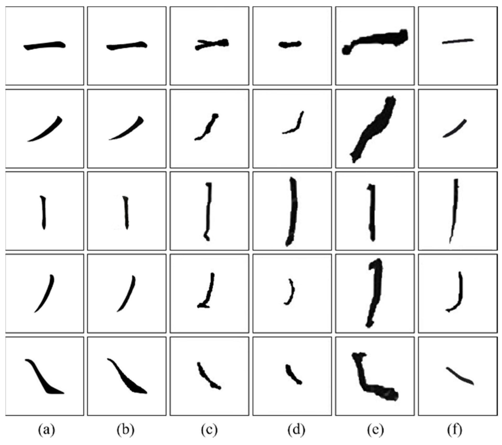
4.2.1. Writing Test of Basic Strokes

The writing results for the stroke “horizontal” are shown in Figure 10. From left to right, these are the reference stroke, the strokes written when the direction of the brush tip is opposite to the writing direction of the horizontal stroke, and the writing result when the direction of the brush tip is the same as the writing direction of the horizontal stroke.
The writing results of the stroke “vertical” are shown in Figure 11. To achieve the writing effect of reference strokes, the process of the robot writing the stroke “vertical” should follow the rule of “intending to go down, first go up”.
Figure 12 and Figure 13 show the writing results of strokes “short left-falling” and “long left-falling” respectively.

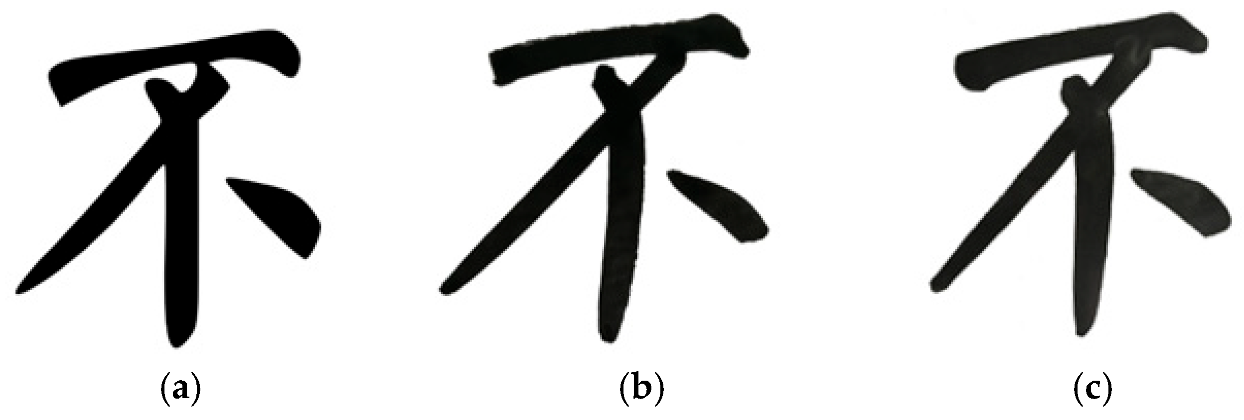
4.2.2. Writing Test of Chinese Characters

Taking the Yan-style calligraphy characters “bu”, as well as the regular script character “qu”, as examples, Figure 14 shows the actual writing result of the character “bu”. From left to right, these are reference calligraphy images, the writing results without the “yunbi” methods and the writing results after incorporating the “yunbi” methods. As can be seen from Figure 15, the writing result improved after adding the “yunbi” methods.
Figure 15 shows the writing result of the character “qu”. Figure 15a is the reference calligraphy image, while Figure 15b,c show the actual writing images by the robotic arm based on the same parameter settings.

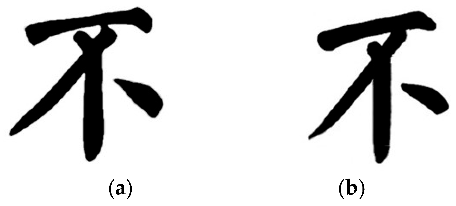
4.2.3. Writing Test with Different Brush Pen

To verify that the writing robot has a good writing ability with different brushes, we conducted a writing test by replacing a different type of brush (No. 2 brush) and evaluated the performance. Figure 16 and Figure 17 show the writing result of the character “bu” and “qu” with the No. 2 brush, respectively. In terms of the overall structure, the Chinese characters written with the No. 2 brush are similar to the reference Chinese characters after applying the three steps of “yunbi”, which indicated that the model has good generalization and robustness for different pens.

4.3. Performance Evaluation

4.3.1. Writing Speed Evaluation

When the robot performs writing tasks, the range of writing speed variation can reflect the stability of the writing process. A smaller speed variation interval indicates a more stable writing process. To further demonstrate the stability of the writing process, we evaluated speed variations during the writing of five basic strokes “horizontal”, “vertical”, “short left-falling”, “long left-falling” and “right-falling”.
The planning writing positions and postures were applied to conduct 100 experimental tests on five strokes, and the results are shown in Table 1. The speed variation ranges of all five strokes were relatively small, with the speed variation range for the stroke “vertical” being only 0.47 mm/s. Figure 18 shows the writing results of strokes “right-falling” at maximum and minimum speed, because it has the largest range of variation. From Figure 18, we can see the results are close to each other at two boundary values. This indicated that the robot could move at a stable speed and guarantee the quality during the writing process, and there will be no impacts caused by sudden speed changes.

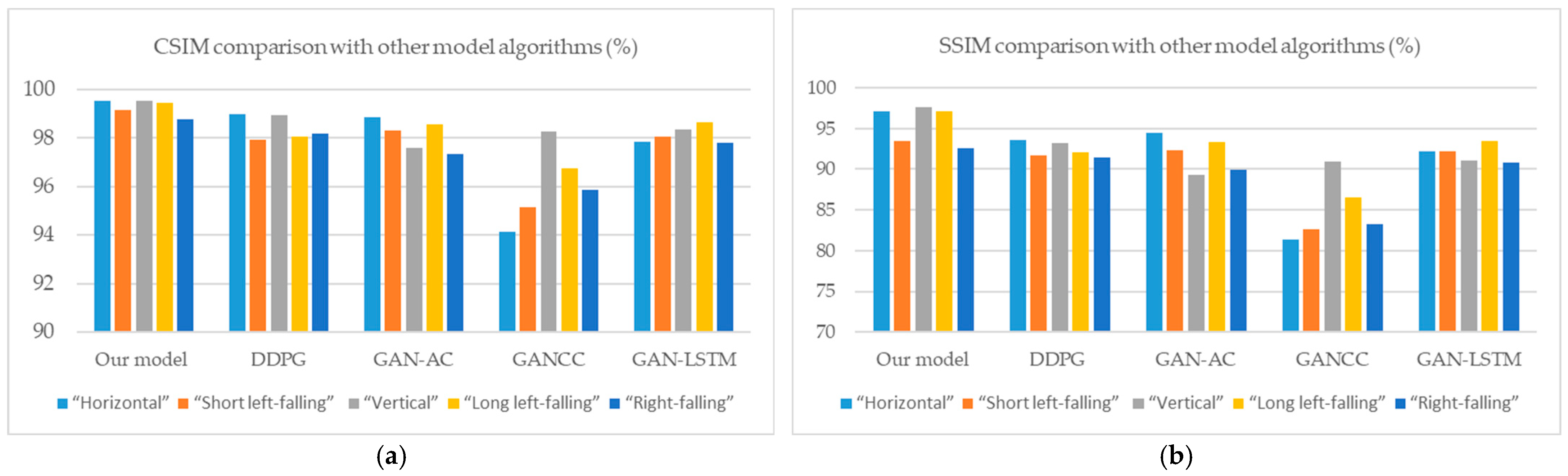
4.3.2. Comparison with Other Model Algorithms

This paper compares the intelligent calligraphy robot system with four advanced robotic calligraphy systems and algorithms, which are the Generative adversarial nets based Chinese calligraphy (GANCC) Chinese calligraphy robot, the generative adversarial network—long short-term memory network (GAN-LSTM) calligraphy robot learning system based on generative adversarial network (GAN) and long short-term memory (LSTM) network, the GAN-AC network model, and the deep deterministic policy gradient (DDPG) algorithm-based generative model. The results of the qualitative comparison are shown in Figure 19. By comparing with the current optimal model and algorithm, the advantages of our proposed writing trajectory control model in stroke generation are demonstrated. Cosine similarity (CSIM) and Structural similarity index measure (SSIM) were used as specific quantitative criteria to evaluate the differences between the different results. The results of 100 experiments written by the robotic end-effector were quantitatively evaluated based on CSIM and SSIM, as shown in Table 2 and Table 3. The average values of CSIM and SSIM of basic strokes written by the robot exceed those of other model algorithms, which indicates that the writing ability for basic strokes based on our proposed model conforms to brush the stroke model with better performance. Figure 20 shows the quantitative comparison results between our system and other models and algorithms.

4.3.3. Writing Similarity Evaluation

The results of 100 experiments were quantitatively evaluated based on CSIM and SSIM, as shown in Table 4. It records the best, worst and average similarity for each stroke. The average CSIM value for all five strokes exceeds 98%, which indicates that the writing ability for basic strokes is strong. It can be seen from Table 4 that the CSIM of the basic stroke “vertical” is the highest, with a maximum similarity of 99.88%.
According to values of CSIM and SSIM in Table 4, among the five strokes, the robot performs better in writing the strokes “horizontal”, “vertical” and “long left-falling”, followed by the stroke “short left-falling”, and is slightly weaker in writing the stroke “right-falling”.
To verify the generalization and robustness of the robotic calligraphy under the varying Chinese character structures and styles, the robot was controlled to conduct 100 writing experiments on Chinese characters with different structures and styles. The writing results were quantitatively evaluated based on the CSIM and SSIM similarity metrics, as shown in Table 5. Table 5 recorded the similarity of each Chinese character written by the robotic end-effector in the best case, the worst case and the average similarity of all Chinese character images. As can be seen from Table 5, the average CSIM of Chinese characters written by the robot exceeds 85%. Based on the average values of CSIM and SSIM, it is evident that the robot based on the proposed model possesses a certain level of writing capability for Chinese characters with different structures.

4.4. Ablation Study

The ablation study was conducted to clarify the contributions of “zhuanbitiaofeng” and “zhebi” to the final quality. Figure 21 shows the writing results of strokes “right-falling” before and after “zhuanbitiaofeng”. Figure 22 shows the writing results of strokes “reclining hooks” before and after “zhebi”. Figure 22b shows the writing result without “zhebi”, while Figure 22c shows the result after incorporating “zhebi”. By adding “zhuanbitiaofeng” and “zhebi”, the final writing quality can be improved significantly.

5. Conclusions and Future Works

This paper primarily studied fine-grained control of robotic brush calligraphy and proposed a robotic writing trajectory control model based on a brush stroke model combined with the stroke rules of brush calligraphy. The speed variation ranges of basic strokes were relatively small, with the stroke “vertical” being only 0.47 mm/s. Compared with other existing methods, the average values of CSIM and SSIM of basic strokes and Chinese characters written by the robot exceed those of other model algorithms. The average CSIM value for all five strokes exceeds 98%, with a maximum similarity of 99.54%. For Chinese characters written by the robot, the average value of CSIM exceeds 85%. Furthermore, as the specifications of brush pens are taken into consideration, the generated strokes and characters under the same posture parameters were different when using pens with different sizes, which leads to good generalization and robustness for different pens.
In the future, more diverse control methods with hairy brushes will be further explored for robotic calligraphy to further improve the robot’s writing capabilities and replication effects. The approach with a machine vision system to self-learning a robotic arm using artificial intelligence will be studied to improve the quality of the models.

Author Contributions

Conceptualization, D.G.; methodology, D.G.; software, D.G.; validation, D.G., W.F. and W.Y.; formal analysis, D.G.; investigation, W.Y.; resources, D.G.; data curation, W.Y.; writing—original draft preparation, D.G.; writing—review and editing, W.F.; visualization, D.G.; supervision, D.G.; project administration, D.G.; funding acquisition, D.G. All authors have read and agreed to the published version of the manuscript.

Funding

This research was funded by the Scientific Research Foundation for High-level Talents of Anhui University of Science and Technology, grant number 2024yjrc39, Hubei Key Laboratory of Intelligent Robot (Wuhan Institute of Technology), grant number HBIR 202407, and Anhui Action Foundation for Cultivating Young and Middle-aged Teachers, grant number JNFX2024015.

Data Availability Statement

The raw data supporting the conclusions of this article will be made available by the authors on request.

Acknowledgments

The authors would like to express their sincere thanks to all partners for knowledge sharing and support for this research.

Conflicts of Interest

The authors declare no conflicts of interest.

Abbreviations

The following abbreviations are used in this manuscript:
CCD-BSMComposite-curve-dilation brush stroke model
CSIMCosine similarity
SSIMStructural similarity index measure
DOFDegree of freedom

References

  1. Guo, D.M.; Min, H.S. Survey of calligraphy robot. Control Decis. 2022, 37, 1665–1674. [Google Scholar] [CrossRef]
  2. Lin, T.T.; She, J. Future Ink: The Collision of AI and Chinese Calligraphy. ACM J. Comput. Cult. Herit. 2025, 18, 1–17. [Google Scholar] [CrossRef]
  3. Zingrebe, D.S.; Gülzow, J.M. Robotic Writing of Arbitrary Unicode Characters Using Paintbrushes. Robotics 2023, 12, 72. [Google Scholar] [CrossRef]
  4. Bai, T.; Guo, C. Parallel calligraphy robot: Framework and system implementation. IEEE J. Radio Freq. Identif. 2022, 7, 163–167. [Google Scholar] [CrossRef]
  5. Mao, Z.; Suzuki, S. Machine learning-enhanced soft robotic system inspired by rectal functions to investigate fecal incontinence. Bio Des. Manuf. 2025, 8, 482–494. [Google Scholar] [CrossRef]
  6. Aksan, E.; Pece, F.; Hilliges, O. Deepwriting: Making digital ink editable via deep generative modeling. In Proceedings of the 2018 CHI Conference on Human Factors in Computing Systems, Montreal, QC, Canada, 21–26 April 2018. [Google Scholar] [CrossRef]
  7. Adamik, M.; Goga, J. Fast robotic pencil drawing based on image evolution by means of genetic algorithm. Robot. Auton. Syst. 2022, 148, 103912. [Google Scholar] [CrossRef]
  8. Karimov, A.; Strelnikov, M. Physically Motivated Model of a Painting Brush for Robotic Painting and Calligraphy. Robotics 2024, 13, 94. [Google Scholar] [CrossRef]
  9. Wen, Y.; Pagilla, P. A 3D path following control scheme for robot manipulators. IFAC Pap. 2020, 53, 9968–9973. [Google Scholar] [CrossRef]
  10. Zhenyu, X.; Fujioka, H. Modeling and manipulating dynamic font-based hairy brush characters using control-theoretic B-spline approach. IFAC Pap. OnLine 2020, 53, 4731–4736. [Google Scholar] [CrossRef]
  11. Peng, Y.H.; Yang, X.Y. Predicting flow status of a flexible rectifier using cognitive computing. Expert Syst. Appl. 2025, 264, 125878. [Google Scholar] [CrossRef]
  12. Chao, F.; Lin, G. An LSTM Based Generative Adversarial Architecture for Robotic Calligraphy Learning System. Sustainability 2020, 12, 9092. [Google Scholar] [CrossRef]
  13. Wu, R.; Zhou, C. GANCCRobot: Generative adversarial nets based chinese calligraphy robot. Inf. Sci. 2020, 516, 474–490. [Google Scholar] [CrossRef]
  14. Wu, R.; Zhou, C. Integration of an actor-critic model and generative adversarial networks for a Chinese calligraphy robot. Neurocomputing 2020, 388, 12–23. [Google Scholar] [CrossRef]
  15. Xiao, Y.; Lei, W. CS-GAN: Cross-structure generative adversarial networks for Chinese calligraphy translation. Knowl.-Based Syst. 2021, 229, 107334. [Google Scholar] [CrossRef]
  16. Liang, D.; Liang, D. A robot calligraphy writing method based on style transferring algorithm and similarity evaluation. Intell. Serv. Rob. 2020, 13, 137–146. [Google Scholar] [CrossRef]
  17. Zhou, P.; Zhao, Z. An end-to-end model for Chinese calligraphy generation. Multimed. Tools Appl. 2021, 80, 6737–6754. [Google Scholar] [CrossRef]
  18. Zhang, X.; Li, Y. Intelligent Chinese calligraphy beautification from handwritten characters for robotic writing. Vis. Comput. 2019, 35, 1193–1205. [Google Scholar] [CrossRef]
  19. Wang, X.; Yang, Y. Generative adversarial networks based motion learning towards robotic calligraphy synthesis. CAAI T. Intell. Techno. 2024, 9, 452–466. [Google Scholar] [CrossRef]
  20. Guo, D.M.; Ye, L. CCD-BSM: Composite-curve-dilation brush stroke model for robotic Chinese calligraphy. Appl. Intell. 2023, 53, 14269–14283. [Google Scholar] [CrossRef]
  21. Wang, Y.; Min, H. Robot calligraphy system based on brush modeling. CAAI Trans. Intell. Syst. 2021, 16, 707–716. [Google Scholar] [CrossRef]
  22. Li, J.; Min, H.S.; Zhou, H.T. Robot Brush-Writing System of Chinese Calligraphy Characters. In Proceedings of the International Conference on Intelligent Robotics and Applications, Shenyang, China, 8–11 August 2019. [Google Scholar] [CrossRef]
  23. Yan, G.; Guo, D.M.; Min, H.S. Robot calligraphy based on footprint model and brush trajectory extraction. In Proceedings of the 7th International Conference on Cognitive Systems and Signal Processing, Fuzhou, China, 18–20 November 2023. [Google Scholar] [CrossRef]
  24. Mueller, S.; Huebel, N.; Waibel, M. Robotic calligraphy—Learning how to write single strokes of Chinese and Japanese characters. In Proceedings of the 2013 IEEE/RSJ International Conference on Intelligent Robots and Systems (IROS), Tokyo, Japan, 3–7 November 2013. [Google Scholar] [CrossRef]
  25. Lin, H.I.; Chen, X. Calligraphy brush trajectory control of by a robotic arm. Appl. Sci. 2020, 10, 8694. [Google Scholar] [CrossRef]
  26. Berio, D.; Calinon, S.; Leymarie, F.F. Generating calligraphic trajectories with model predictive control. In Proceedings of the 43rd Graphics Interface Conference, Edmonton, AB, Canada, 16–19 May 2017. [Google Scholar]
  27. Wu, R.; Chao, F. Internal model control structure inspired robotic calligraphy system. IEEE Trans. Ind. Inf. 2023, 20, 2600–2610. [Google Scholar] [CrossRef]
  28. Berio, D.; Leymarie, F.F. Interactive generation of calligraphic trajectories from Gaussian mixtures. In Mixture Models and Applications; Springer Nature: Cham, Switzerland, 2020; pp. 23–38. [Google Scholar]
  29. Berio, D.; Calinon, S.; Leymarie, F.F. Learning dynamic graffiti strokes with a compliant robot. In Proceedings of the 2016 IEEE/RSJ International Conference on Intelligent Robots and Systems (IROS), Daejeon, Republic of Korea, 9–14 October 2016. [Google Scholar] [CrossRef]
  30. Huebel, N.; Mueggler, E.; Waibel, M. Towards robotic calligraphy. In Proceedings of the 2012 IEEE/RSJ International Conference on Intelligent Robots and Systems (IROS), Vilamoura-Algarve, Portugal, 7–12 October 2012. [Google Scholar] [CrossRef]
  31. Wang, S.; Chen, J.; Deng, X. Robot calligraphy using pseudospectral optimal control in conjunction with a novel dynamic brush model. In Proceedings of the 2020 IEEE/RSJ International Conference on Intelligent Robots and Systems (IROS), Las Vegas, NV, USA, 25–29 October 2020. [Google Scholar] [CrossRef]
  32. Ma, Z.; Su, J. Aesthetics evaluation for robotic Chinese calligraphy. IEEE Trans. Cogn. Dev. Syst. 2016, 9, 80–90. [Google Scholar] [CrossRef]
Figure 1. Writing trajectory control model and robot writing effects.
Electronics 14 03000 g001
Figure 2. The writing trajectories of the “bifeng” and brush handle during the “xingbi”.
Electronics 14 03000 g002
Figure 3. The arc trajectory formed during “zhuanbitiaofeng”.
Electronics 14 03000 g003
Figure 4. The trajectory of the brush folding process: (a) without “zhebi”; (b) with “zhebi”.
Electronics 14 03000 g004
Figure 5. Writing trajectory control based on the stroke model CCD-BSM.
Electronics 14 03000 g005
Figure 6. The writing trajectory control of the brush stroke model during the phase of “xingbi”.
Electronics 14 03000 g006
Figure 7. Brush movement in the stroke initiation phase: (a) “nifengrubi”; (b) “shunfengrubi”.
Electronics 14 03000 g007
Figure 8. Brush stroke movements during the stage of “shoubi”: (a) “changfengshoubi”; (b) “loufengshoubi”.
Electronics 14 03000 g008
Figure 9. Hardware architecture for experiments: (a) shows the hardware architecture of the robotic calligraphy system; (b) shows the brush pens used in the experiments.
Electronics 14 03000 g009
Figure 10. Writing results of “horizontal” stroke (No. 1 brush): (a) reference stroke image; (b) the direction of “bifeng” is opposite to the direction of “yunbi”; (c) the direction of “bifeng” is the same as the direction of “yunbi”.
Electronics 14 03000 g010
Figure 11. Writing results of “vertical” stroke (No. 1 brush): (a) reference stroke image; (b) “shoubi” when H = 15   mm ; (c) “shoubi” when H = 0   mm .
Electronics 14 03000 g011
Figure 12. Writing results of “short left-falling” stroke (No. 1 brush): (a) reference stroke image; (b) “zhongfengxingbi”; (c) “cefengxingbi”.
Electronics 14 03000 g012
Figure 13. Writing results of “long left-falling” stroke (No. 1 brush): (a) reference stroke image; (b) “zhongfengxingbi”; (c) “cefengxingbi”.
Electronics 14 03000 g013
Figure 14. Writing results of character “bu” (No. 1 brush): (a) reference image of character “bu”; (b) writing without “yunbi”; (c) writing with “yunbi”.
Electronics 14 03000 g014
Figure 15. Writing results of character “qu” (No. 1 brush): (a) reference image of character “qu”; (b) writing without “yunbi”; (c) writing with “yunbi”.
Electronics 14 03000 g015
Figure 16. Writing result of character “bu” (No. 2 brush): (a) reference calligraphy image; (b) the actual writing image.
Electronics 14 03000 g016
Figure 17. Writing result of character “qu” (No. 2 brush): (a) reference calligraphy image; (b) the actual writing image.
Electronics 14 03000 g017
Figure 18. Writing results of strokes “right-falling” at maximum and minimum speed: (a) writing at maximum speed; (b) writing at minimum speed.
Electronics 14 03000 g018
Figure 19. Qualitative comparison between our system and other models and algorithms: (a) reference images; (b) writing results of our system; (c) DDPG algorithm; (d) GAN-AC model; (e) GANCC model; (f) GAN-LSTM model.
Electronics 14 03000 g019
Figure 20. Quantitative comparison between our system and other models and algorithms: (a) CSIM comparison with other model algorithms (%); (b) SSIM comparison with other model algorithms (%).
Electronics 14 03000 g020
Figure 21. Writing results of “right-falling” stroke: (a) reference stroke image; (b) shoubi without “zhuanbitiaofeng”; (c) shoubi with “zhuanbitiaofeng”.
Electronics 14 03000 g021
Figure 22. Writing results of “reclining hooks” stroke: (a) reference stroke image; (b) shoubi without “zhebi”; (c) shoubi with “zhebi”.
Electronics 14 03000 g022
Table 1. Writing speed changes of basic strokes (mm/s).
StrokesMaximum SpeedMinimum SpeedRange of Variation
“Horizontal”22.8721.321.55
“Short left-falling”20.1519.540.61
“Vertical”20.2819.810.47
“Long left-falling”21.6620.231.43
“Right-falling”22.7220.951.77
Table 2. CSIM comparison with other model algorithms (%).
System, Model“Horizontal”“Short Left-Falling” “Vertical”“Long Left-Falling”“Right-Falling”
Our model 99.5299.1799.5499.4698.76
DDPG98.9797.9498.9598.0498.17
GAN-AC98.8598.3197.6198.5897.34
GANCC94.1395.1598.2896.7795.87
GAN-LSTM97.8698.0698.3798.6697.80
Table 3. SSIM comparison with other model algorithms (%).
System, Model“Horizontal”“Short Left-Falling” “Vertical”“Long Left-Falling”“Right-Falling”
Our model97.1793.4497.5797.1192.55
DDPG 93.5691.6693.2392.1491.39
GAN-AC94.4392.3589.3393.3289.94
GANCC81.3982.5990.9086.5583.23
GAN-LSTM92.1892.2191.0393.4190.85
Table 4. CSIM and SSIM of basic strokes writing experiment (%).
StrokesCSIM_MaxCSIM_MinCSIM_AvgSSIM_MaxSSIM_MinSSIM_Avg
“Horizontal”99.8199.3499.5297.7996.9597.17
“Short left-falling”99.3199.0699.1794.3293.1693.44
“Vertical”99.8899.4099.5498.0697.2797.57
“Long left-falling”99.7299.2999.4697.4096.6997.11
“Right-falling”99.0198.3398.7693.5692.2092.55
Table 5. CSIM and SSIM of Chinese characters writing experiment (%).
CharactersCSIM_MaxCSIM_MinCSIM_AvgSSIM_MaxSSIM_MinSSIM_Avg
“bu”90.1984.0986.6166.5162.1063.81
“qu”95.8986.0888.7373.3264.9468.73
Disclaimer/Publisher’s Note: The statements, opinions and data contained in all publications are solely those of the individual author(s) and contributor(s) and not of MDPI and/or the editor(s). MDPI and/or the editor(s) disclaim responsibility for any injury to people or property resulting from any ideas, methods, instructions or products referred to in the content.

