Article

Torque Ripple Reduction in BLDC Motors Using Phase Current Integration and Enhanced Zero Vector DTC

School of Mechanical and Materials Engineering, North China University of Technology, Beijing 100043, China
*
Author to whom correspondence should be addressed.
Electronics 2025, 14(15), 2999; https://doi.org/10.3390/electronics14152999
Submission received: 1 July 2025 / Revised: 21 July 2025 / Accepted: 23 July 2025 / Published: 28 July 2025
(This article belongs to the Section Power Electronics)

Abstract

To improve commutation accuracy and effectively suppress torque ripple in brushless DC motors (BLDCMs), this paper presents a novel commutation correction strategy integrated into an enhanced direct torque control (DTC) framework. The proposed method estimates the commutation angle error in real time by analyzing the integral difference in phase currents across adjacent 30° conduction intervals, enabling dynamic and accurate commutation correction. This correction mechanism is seamlessly embedded into a modified DTC algorithm that employs a three-level torque hysteresis comparator and introduces a novel zero-voltage vector selection strategy to minimize torque ripple. Compared with conventional DTC approaches employing dual-loop control and standard zero vectors, the proposed method achieves up to a 58% reduction in torque ripple along with improved commutation precision, as demonstrated through both simulation and experimental validation. These results confirm the method’s effectiveness and its potential for application in high-performance BLDCMs drive systems.

1. Introduction

With the continuous advancement of industrial automation, brushless DC motors (BLDCMs) have been extensively utilized in applications, such as power tools, electric vehicles, and intelligent manufacturing, owing to their compact structure, high efficiency, and low noise characteristics [1,2]. Compared to conventional brushed motors, BLDCMs enable contactless operation via electronic commutation, thereby significantly enhancing system reliability [3,4]. Furthermore, BLDCMs play a critical role in various autonomous systems, including robotics, unmanned aerial vehicles (UAVs), and image-guided industrial equipment, where their superior torque and speed control capabilities make them indispensable for achieving high-precision and real-time motion execution [5].
The electronic commutation strategies of BLDCMs can be broadly categorized into the following three types: position-sensor-based methods, back electromotive force (BEMF) detection methods, and model-based estimation approaches. Traditionally, devices such as Hall sensors or rotary encoders are employed to acquire rotor position information and trigger commutation. Although these methods are relatively simple to implement, their reliability is compromised in harsh environments such as high temperatures or humidity, and they often incur higher system costs. To address these limitations and improve system integration, sensorless control techniques have been extensively studied and widely adopted [6]. Mainstream sensorless methods include BEMF zero-crossing point (ZCP) detection, BEMF amplitude estimation, stator inductance variation analysis, and model-based observers such as sliding mode observers and extended Kalman filters [7]. Among these, the BEMF-ZCP method is the most widely applied due to its low hardware complexity and ease of implementation. It determines the commutation instant by detecting the zero-crossing of the terminal voltage of the non-conducting phase [8]. However, in practical applications, non-ideal BEMF waveforms, signal delays, device drift, and electrical noise often introduce commutation errors. These errors can result in current distortion, torque ripple, and reduced system efficiency, particularly under high-speed or sudden load conditions [9,10,11]. Therefore, the development of accurate commutation error compensation strategies is essential for improving the performance and robustness of BLDCMs drive systems.

1.1. Related Work

Currently, commutation error correction methods can be broadly categorized into two types. The first type focuses on analyzing system errors and compensating for them individually. For instance, at low speeds, the back-EMF has a low signal-to-noise ratio, which may lead to detection errors in commutation signals. Zhou et al. proposed amplifying and then detecting the phase voltage to extract the back-EMF zero-crossing point [12]. To address the phase lag of the commutation point caused by low-pass filters and software delay [13], Guo et al. analyzed the commutation error resulting from filter phase shift and software delay in motor drive systems, derived the error expression, and determined the phase compensation amount for the control system accordingly [14]. However, such methods are mainly applicable to phase delay and signal processing lag scenarios, and are limited in achieving real-time and accurate commutation correction. The second type of method determines the optimal commutation instant based on certain performance indicators or physical characteristics of the system. For example, based on the relationship between phase current and back-EMF, Zhang H. et al. proposed a commutation error construction and correction method utilizing phase synchronization between back-EMF and phase current. A novel function is constructed to directly extract the commutation error, and a Fourier synchronous filter is used for signal filtering and correction [15]. Similarly, D. Zhao et al. proposed a fast commutation error compensation method based on virtual neutral voltage [16]. The compensation time is calculated using a counter, and a digital logic circuit is employed to trigger the compensation signal, effectively reducing commutation errors. However, the commutation judgment in this method heavily relies on the quality of the virtual neutral voltage, which is susceptible to PWM interference and circuit noise, thereby limiting its practical applicability. In addition, researchers have proposed current integration methods for different speeds and operating conditions. For instance, Ref. [17] utilized the symmetry of phase currents and proposed a real-time commutation error correction method based on phase current integration. The correction process is divided into incremental compensation steps, effectively eliminating the commutation error. References [18,19] indirectly determined the accurate commutation instant by enforcing equal phase current integrals over the two half-periods of a 60° conduction cycle.
Although the above methods improve commutation accuracy under various speeds and conditions, they essentially rely on indirect estimation of the commutation instant and lack control over the motor’s output characteristics, particularly its torque dynamic response. In motor control systems, precise commutation timing not only affects the symmetry of current waveforms, but also directly influences the motor’s output torque and dynamic performance. Therefore, enhancing commutation accuracy and integrating it with direct torque control methods is of great significance for improving control precision and robustness under high-speed and highly dynamic operating conditions [20].
Among the various methods for suppressing torque ripple, Direct Torque Control has gained increasing attention due to its direct regulation of electromagnetic torque, which is less susceptible to uncertain ripple-inducing factors [21]. However, in conventional torque hysteresis control the application of the zero-voltage vector may, under certain conduction states, aggravate current spikes and torque fluctuations. To address this, studies in [22,23] analyzed the significant torque oscillations and insufficient control accuracy associated with traditional two-level hysteresis comparators and proposed a three-level torque comparator combined with a simplified space vector selection table to enhance torque regulation. Nevertheless, this approach sacrifices control precision and system robustness for simplified implementation, thereby limiting its adaptability under complex operating conditions. In [24], a DTC method incorporating space vector pulse width modulation (SVPWM) and an optimized PI controller was proposed. Although the optimized PI controller demonstrated good performance in simulations, issues such as slow convergence, poor adaptability to load variations, and high computational complexity remain unresolved.

1.2. Research Objectives and Contributions

Based on the advantages and limitations of the aforementioned methods, this paper proposes a torque optimization control strategy that integrates a phase compensation technique based on phase current integration with a direct torque control scheme employing a novel space zero-voltage vector. On the one hand, real-time integration of phase current provides error feedback for dynamic commutation error compensation, thereby improving commutation accuracy. On the other hand, a newly designed zero-voltage space vector—aligned with the back-EMF direction of the non-conducting phase—is introduced to dynamically regulate electromagnetic torque, aiming to smooth torque output and enhance system robustness. The proposed strategy offers a feasible and high-performance control solution for sensorless BLDCMs systems.
The structure of this paper is organized as follows: Section 2 provides a brief overview of the fundamental principles of BLDCMs and DTC scheme, and introduces a commutation error correction method based on phase current integration along with a novel zero-voltage space vector construction strategy. Section 3 presents the development of the corresponding simulation model and offers detailed explanations of the key modules and parameter configurations. Section 4 validates the stability and robustness of the proposed control strategy through both simulations and experiments under representative conditions such as varying rotational speeds and sudden load changes. The results confirm that the system maintains favorable dynamic response and convergence performance across all tested scenarios. Section 5 concludes the study and outlines potential directions for future research.

2. Direct Torque Control Strategy Based on Phase Current Integration

Accurate determination of the commutation instant is critical for achieving smooth electromagnetic torque output in BLDCMs control. To effectively suppress torque ripple induced by commutation errors, this paper presents a commutation correction strategy based on phase current integration, integrated into an enhanced DTC framework. The proposed method dynamically estimates the commutation angle error by analyzing the integral difference in phase currents, thereby improving commutation accuracy. Furthermore, a novel zero-voltage vector aligned with the back-EMF direction of the non-conducting phase is introduced to smooth torque output and enhance dynamic performance. The specific control strategy is detailed as follows.

2.1. Analysis of Commutation Correction Based on Phase Current Integration

When the motor undergoes inaccurate commutation, the difference in the phase current integral during the 30° conduction intervals before and after the back-EMF zero-crossing can be used to determine whether the commutation is advanced or delayed. By adjusting the delay time following the zero-crossing detection, the commutation angle can be modified such that the integral of the phase current in the first half of each 60° conduction period becomes equal to that in the second half, thereby achieving accurate commutation.
For a star-connected BLDCMs, the equivalent voltage equation under the two-phase-on conduction mode (six-step commutation) can be expressed as follows:
u ao = R i a + L d i a d t + e a + U n u bo = R i b + L d i b d t + e b + U n u co = R i c + L d i c d t + e c + U n
where u ao ,   u bo ,   u co are the three-phase line voltages ( V ) ; i a ,   i b ,   i c are the phase currents ( A ) ; L is the winding inductance ( H ) ; e a ,   e b ,   e c are the three-phase back electromotive forces ( V ) ; and U n is the virtual center point voltage ( V ) .
Figure 1 shows the ideal back electromotive force waveform when commutation delay occurs. When the motor operates in the 60–120° range, phase A and phase C are conducting u a o = D u d c ,   u c o = 0 ,   i a = i c . Substituting this into Equation (1) gives the following relationship between terminal voltage and current:
u ao = D u d c = i a Z + e a + U n u bo = e b + U n u co = 0 = i c Z + e c + U n
where Z is the motor impedance coefficient ( Ω ) , and D is the PWM duty cycle. By Substituting i a = i c into the above formula, the phase current of phase A can be obtained as follows:
i a = D u d c e a + e c 2 Z
For the ideal back electromotive force waveform during phase shift delay, there is the following:
e a = k e ω e θ 60 ° θ θ 120 ° k e ω e 6 k e ω e π × θ θ 120 ° θ θ 120 ° + α e c = k e ω e θ 60 ° θ θ 120 ° + α
where k e is the back electromotive force coefficient, θ is the electrical angle ( r a d / s ) , and ω e is the electrical angular speed of the motor. By substituting Equation (4) into Equation (3) and integrating the phase current over the first half of the interval, we obtain the following:
θ 60 ° + α θ 90 ° + α i a ( θ ) = 1 2 Z θ 60 ° + α θ 90 ° + α ( D u d c 2 k e ω e ) d θ
Similarly, after simplification, the integral of the phase current in the range of θ 90 ° + α θ 120 ° + α can be obtained as follows:
θ 90 ° + α θ 120 ° + α i a ( θ ) = 1 2 Z ( θ 60 ° + α θ 90 ° + α ( D u d c 2 k e ω e ) d θ + 3 k e ω e π θ α 2 )
where θ α represents the lagging electrical angle. Therefore, subtracting Equation (5) from (6) gives the difference in the integral of the phase currents over the two segments of electrical angles from θ 60 ° + α θ 120 ° + α , which is as follows:
Δ i a ( θ ) = θ 60 ° + α θ 90 ° + α i a ( θ ) θ 90 ° + α θ 12 ° + α i a ( θ ) = 3 k e ω e π θ α 2
Similarly, when the motor advances the commutation we obtain the following:
Δ i a ( θ ) = θ 60 ° + α θ 90 ° + α i a ( θ ) θ 90 ° + α θ 120 ° + α i a ( θ ) = 3 k e ω e π θ α 2
In addition, it is necessary to calculate the time corresponding to the 60° electrical angle as follows:
f e l e c = N × P 60
where N represents the motor speed ( r p m ) , and P represents the number of pole pairs of the motor. The time corresponding to a 60° electrical angle at different speeds is as follows:
T 60 = 1 6 × f e l e c = 5 N
Based on the phase current integration theory described above, this method enables accurate identification and dynamic correction of commutation errors. However, even with precise commutation, conventional DTC still exhibits a certain degree of torque fluctuation during voltage vector switching. To address this issue, this paper proposes a novel zero-voltage vector-based DTC strategy to achieve improved torque stability.

2.2. Optimization of Direct Torque Control Based on New Zero Vector

Direct torque control is a control method that enables direct regulation of motor torque to achieve rapid torque response [25]. It typically involves acquiring the stator voltage and current to calculate the estimated values of electromagnetic torque and stator flux. These estimated values are then compared with their respective reference values, and, together with the sector position information, are fed into hysteresis comparators to generate control signals. These signals are used to select the optimal voltage space vector from a predefined switching table, thereby enabling direct control of torque and flux [26,27]. Figure 2 illustrates the block diagram of direct torque control for BLDCMs.
Traditional direct torque control uses a binary hysteresis comparator to assess the torque error, with the output being either 1 or 0. This method causes the torque error Δ T e to oscillate between upper and lower thresholds, resulting in significant torque ripple that adversely affects system stability. To reduce torque ripple near the threshold, this paper adopts a ternary hysteresis comparator as the control strategy for torque regulation. The space voltage vector is denoted as V x ( A + A B + B C + C ) , where A, B, and C correspond to the upper and lower bridge arms of each inverter phase leg. A binary value of ‘1’ indicates that the corresponding switch is conducting, while ‘0’ indicates it is turned off. The voltage vector selection table for the ternary hysteresis comparator is shown in Table 1. When Δ T e falls within the threshold range ( Δ T 1 < Δ T e < Δ T 1 ) , the comparator outputs a corresponding control signal, enabling finer control of the system. The presence of an intermediate state enhances the system’s robustness and anti-interference capability, leading to smoother system output transitions. The control principle of the ternary hysteresis comparator is illustrated in Figure 3.
The control output relationship of the three-value hysteresis comparator is shown in Equation (11) as follows:
τ = 1 Δ T e > Δ T 1 0 Δ T 1 < Δ T e < Δ T 1 1 Δ T e < Δ T 1
where τ is the output value of the controller and Δ T 1 is the hysteresis boundary threshold.
Taking Sector I of the ternary hysteresis comparator control process as an example, the comparator output at this moment is 1. According to Table 1, the system responds by applying the voltage space vector V 2 ( 001001 ) to increase the motor torque. During this process, Δ T e decreases continuously. When Δ T e falls within the predefined threshold range, the comparator output switches to 0, thereby maintaining the motor torque within the threshold range.
As shown in Figure 4, the schematic diagram of BLDCMs drive system includes MOSFET switches Q 1 Q 6 and their corresponding freewheeling diodes D 1 D 6 . R a R c and L a L c represent the stator resistance and inductance of each phase, respectively. At this moment phase A is turned off, while phases B and C are conducting, and the corresponding voltage space vector is V 2 ( 001001 ) . The current enters the motor through the lower bridge arm of phase B and exits through the lower bridge arm of phase C. In the next interval, if the active switching vector changes to V 0 , the corresponding conduction state is illustrated in Figure 5. In this case, the current flows into the motor through the diode of the lower bridge arm of phase B and exits through the diode of the upper bridge arm of phase C. There exists u b o = 0 , u c o = u d c , and the voltage balance equation at the motor terminals can be written as follows:
0 = R i b + L s d i b d t + e b + U n u d c = R i c + L s d i c d t + e c + U n u ao = e a + U n
where U n denotes the DC bus voltage and L s represents the equivalent inductance. At this time, since the back electromotive force of the motor is related to the rotor angular velocity, we have i b = i c , e b = e c = E ( E denotes the amplitude of the back electromotive force ( V ) ). Here, it is assumed that the rate of change in the phase currents of B and C remains equal during the short time of continuous current flow. By adding the expressions for the terminal voltages of phases B and C in Equation (12), we can obtain the neutral point voltage U n = 1 / 2 u d c , thus rewriting the phase voltage balance equation as follows:
u a = 1 2 u d c = e a u b = 1 2 u d c = R i b + L s d i b d t + e b u c = 1 2 u d c = R i c + L s d i c d t + e c
By analyzing the stator phase space voltage vector, the continuous current state generated under the conduction state of the V 0 ( 000000 ) voltage vector is equivalent to the effect of the V 5 ( 000110 ) voltage space vector. That is, under conduction by zero vector, the continuous current effect generates a voltage space vector that is completely opposite in direction to the V 2 vector. Therefore, under the influence of the conventional zero vector, the intended effect of suppressing the torque rise to maintain output stability is not achieved; instead, the torque decreases rapidly. In Equation (13), the stator resistance is typically assumed to be small, and its effect on the electromagnetic torque is neglected. Thus, we have the following:
d i b d t = u d c + 2 E 2 L s d i c d t = u d c + 2 E 2 L s
In this steady-state condition, the rate of change in electromagnetic torque is as follows:
d T e d t = k e ( d i b d t + d i c d t ) = k e ( u d c + 2 E ) L s
From Equation (14), it can be seen that at this time the absolute values of the current change rates of phase B and phase C are equal, which satisfies the condition u d c = 4 E . Therefore, Equation (15) can be simplified to the following:
d T e d t = k e 6 E L s
It can be seen that the conventional zero vector V 0 ( 000000 ) fails to stabilize the motor torque. To address this a new type of voltage vector is introduced by simultaneously turning on the upper and lower bridge arms of two phases while maintaining the original direction of the current flow. This enables the system to generate a spatial voltage vector aligned with the rotor direction when the output of the three-level hysteresis comparator transitions from 1 (or −1) to 0. This new voltage vector has minimal influence on the torque, thereby reducing the torque fluctuations that typically occur during motor operation.
As shown in Figure 6, when the switching transistors Q4 and Q6 are turned on, the corresponding conduction state is defined as V 60 ( 000101 ) . After the spatial voltage vector V 2 ( 001001 ) is disabled, the direction of current flow remains unchanged, which leads to the following:
u b o = 0 = i b R b + L d i b d t + e b + U n u c o = 0 = i c R c + L d i c d t + e c + U n
By adding the two equations above and neglecting the influence of the stator resistance on the electromagnetic torque, we obtain i b = i c , e b = e c = E , which yields the following:
d i b d t = E L s d i c d t = E L s
Under this continuous current condition, the rate of change in the electromagnetic torque is given by the following:
d T e d t = k e ( d i b d t + d i c d t ) = k e 2 E L s
By comparing Equation (19) with Equation (15), it can be observed that the use of the new zero vector can suppress torque ripple generated during the continuous conduction state to a certain extent. The phase voltage balance equation of the motor at this time is as follows:
u a = u a o U n = e a u b = u b o U n = 0 u c = u c o U n = 0
where u x represents the three-phase phase voltage, u xo denotes the three-phase line voltage, and U n refer to the neutral point voltage. It can be observed that the direction of the V 60 space voltage vector is consistent with the back electromotive force direction of the non-conducting phase (Phase A) at that moment. Similarly, it can be concluded that the directions of the other five new zero vectors are also aligned with the back-EMF direction of the corresponding non-conducting phase. Consequently, the voltage vector distribution diagram for all new zero vectors is obtained, as illustrated in Figure 7.
According to Figure 7, the newly revised three-value hysteresis voltage vector selection table is shown in Table 2.

3. Simulation Verification Model Construction

A simulation model of BLDCMs was built on the Simulink platform to verify the effectiveness of the novel torque ripple control algorithm for BLDCMs proposed in this article. The simulation model is shown in Figure 8.
The phase current integration module primarily consists of the following: conduction moment detection module, phase current integration module, commutation compensation angle calculation module, delay module, etc. As shown in Figure 9, the conduction moment detection module takes three-phase current, rotor sector position, and motor speed as input signals. During motor operation, the conduction moments of two of the three phases are determined based on the sector position signal of the rotor. When the sector conditions are met, the integrator is triggered to start integrating the phase current during the conduction period.
Figure 10 shows the current integration module (taking phase A as an example). This module calculates the conduction time T60 for a 60° electrical cycle at the current motor speed. For the integration of the first 30° of the electrical cycle, a high-level signal with a duration of 0–T30 is generated based on the conduction time T30 of the first 50%, which is used to enable the integrator for the integration calculation of the first 30° electrical cycle. For the integration of the last 30° of the electrical cycle, a high-level signal with a duration of 0–T60 is used to activate the integrator, and the difference between the two integration values gives the current integration T30–60 for the last 30° electrical cycle.
Figure 11 presents the commutation compensation angle calculation module, which operates based on Equations (8) and (9). This module uses the calculated integral values from the preceding and following segments to compute their difference. Based on this difference, the module determines a threshold range and evaluates whether the current phase is leading or lagging. It then calculates the corresponding commutation compensation angle and forwards it to the commutation delay module to determine the accurate commutation point.
Figure 12 illustrates the delay compensation module, which delays the zero-crossing signal by a 30° electrical angle to determine the commutation moment. Meanwhile, it compensates for phase shifts introduced by the second-order low-pass filter, as well as errors caused by leading or lagging commutation. This ensures accurate delay time calculation, thereby completing the entire process from phase current integration to precise commutation.
For the direct torque control part, the voltage collected at the terminal is processed and introduced into the sector judgment module for logical determination to obtain the rotor sector signal. The sector judgment module is shown in Figure 13.
By employing a speed outer loop and torque hysteresis loop, the difference between the target speed and the speed feedback is input into a PID controller to generate the torque reference value. Subsequently, the difference between the torque reference and the feedback value is compared with a threshold using a three-value hysteresis comparator, which produces the corresponding control signal. The three-value hysteresis comparator module is shown in Figure 14.
The output signal of the three-value hysteresis comparator and the rotor sector signal are introduced into the sector-voltage vector lookup table module to obtain the real-time spatial voltage vector, as shown in Figure 15.
When the three-value hysteresis comparator outputs 0, which corresponds to the conduction of the zero vector, a new type of zero vector will be introduced based on Table 2, and a corresponding new type of zero vector module will be established, as shown in Figure 16.
After the spatial voltage vector is selected, the duty cycle signal calculated from the current control loop is fed into the PWM generation module. Combined with the spatial voltage vector, this signal is used to generate the conduction signals for the upper and lower bridge arms.

4. Analysis of Simulation Results and Experimental Verification

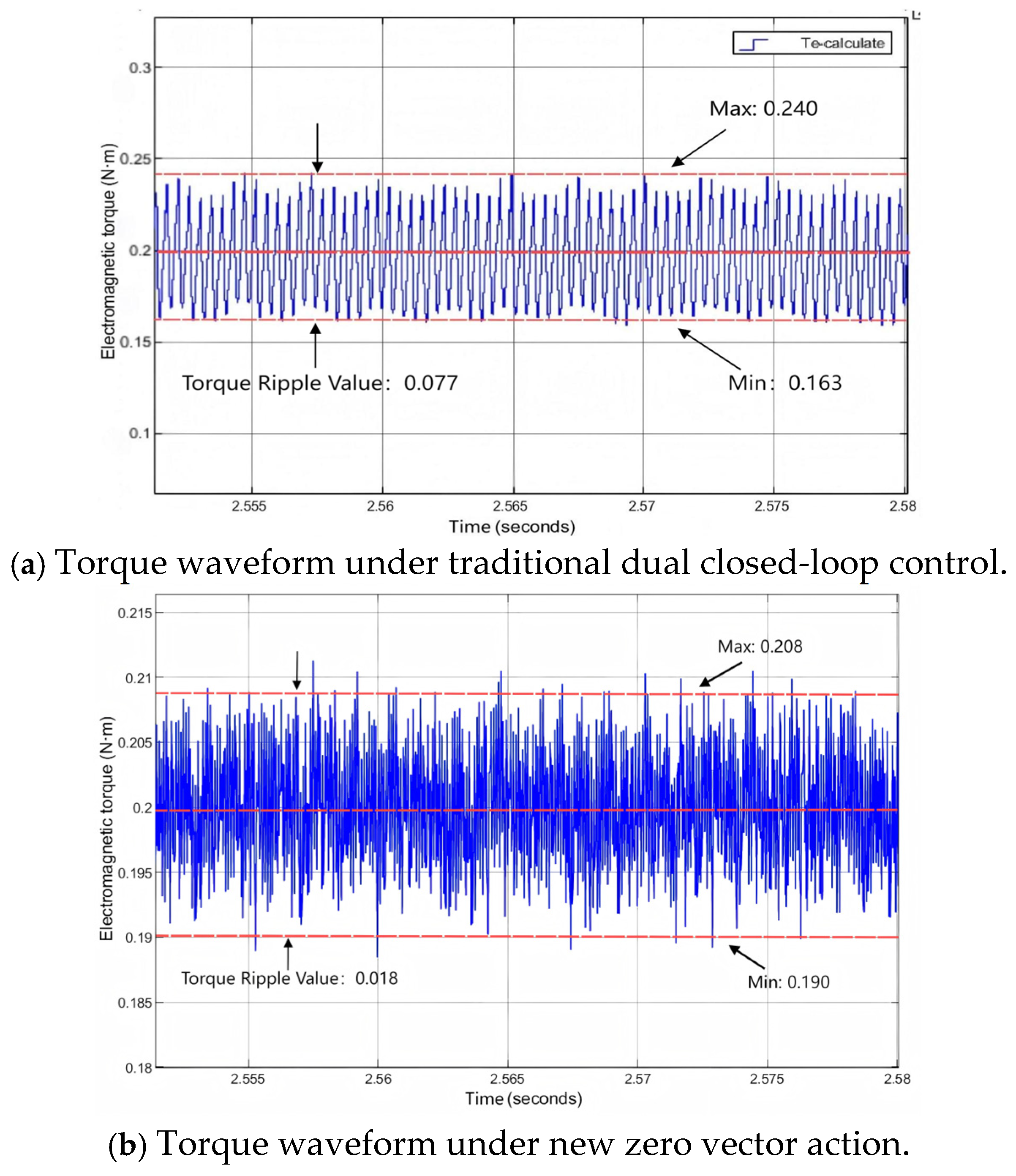
4.1. Simulation Research

The simulation work in this study was conducted using the MATLAB/Simulink R2023b platform, running on a computer equipped with an Intel Core i7-14700KF processor and 32 GB of RAM under the Windows 10 operating system. The parameters of the BLDCMs module in the simulation model are shown in Table 3.
Set the simulation sampling period to 5 × 10⁻⁶ s. The system runs the startup acceleration program for 7 s, with the initial load torque of the motor at 0.2 N · m , and after 7 s the load torque rises to 0.5 N · m .
When the commutation error correction is not applied, the phase current waveform will exhibit issues such as peak currents and waveform asymmetry. At the same time, leading and lagging commutation can also cause a phase difference between the phase current and the back electromotive force waveform (taking 3000 rpm as an example), as shown in Figure 17, Figure 18 and Figure 19.
The phase current integration algorithm is incorporated to ensure the correct phase alignment between the phase current and the back electromotive force (EMF), thereby enabling accurate commutation. The phase current integration waveform, before and after commutation under accurate conditions, is presented in Figure 20.
Figure 20 illustrates the integral waveforms of phase current over two adjacent 30° conduction intervals as the motor accelerates from standstill to full speed and reaches steady operation. The maximum values are 2.8 × 10⁻³ and 2.6 × 10⁻³, respectively, with a difference of only 0.0002. This indicates that the integral values are nearly equal, suggesting a high degree of symmetry in current integration. To evaluate the effectiveness of commutation correction at different speeds, representative speeds of 3000 rpm, 5000 rpm, 8000 rpm, and 10,000 rpm are selected for analysis, as illustrated in Figure 21.
Figure 21a–d present the A-phase current waveforms after applying the phase current integration correction at different motor speeds. It can be observed that under accurate commutation conditions, the phase current waveforms exhibit minimal distortion and remain in phase with the back electromotive force (EMF). Although current spikes are still present, the distortion is significantly suppressed across all speeds.
As the motor speed increases, the time corresponding to each 60° electrical conduction interval decreases. At lower speeds, the integration error between the two 30° segments within each 60° period is relatively small, resulting in effective correction and phase alignment between the current and back EMF. However, at higher speeds, the duration of the 60° conduction interval becomes shorter, making the variation in conduction time a more significant portion of the interval. This leads to increased integration error and a reduced correction effect, resulting in a noticeable phase shift between the phase current and the back EMF.
To further assess the impact of the phase current integration correction algorithm on DTC, simulations were carried out to compare traditional dual closed-loop control with the proposed zero vector DTC strategy, under the condition of accurate commutation. Figure 22, Figure 23 and Figure 24 show the resulting torque waveforms at motor speeds of 5000 rpm, 8000 rpm, and 12,000 rpm, respectively.
From the comparison of Figure 22a,b, Figure 23a,b and Figure 24a,b, it can be seen that under traditional dual closed-loop control the torque fluctuation is between 0.077~0.258 N · m ; under the influence of the new zero vector the torque waveform is between 0.018~0.185 N · m , with a significant reduction in fluctuation amplitude. By averaging the torque pulsations measured at different speeds, the average torque fluctuation under traditional dual closed-loop control is 0.174 N · m , while under the influence of the new zero vector the average torque fluctuation is 0.073 N · m , which represents a 58% reduction in torque pulsation compared to the traditional dual closed-loop’s direct torque control with zero vector.
The above simulation results demonstrate that the proposed direct torque control method, incorporating phase current integration and a novel zero-voltage vector, significantly enhances torque observation accuracy and effectively suppresses motor torque ripple.

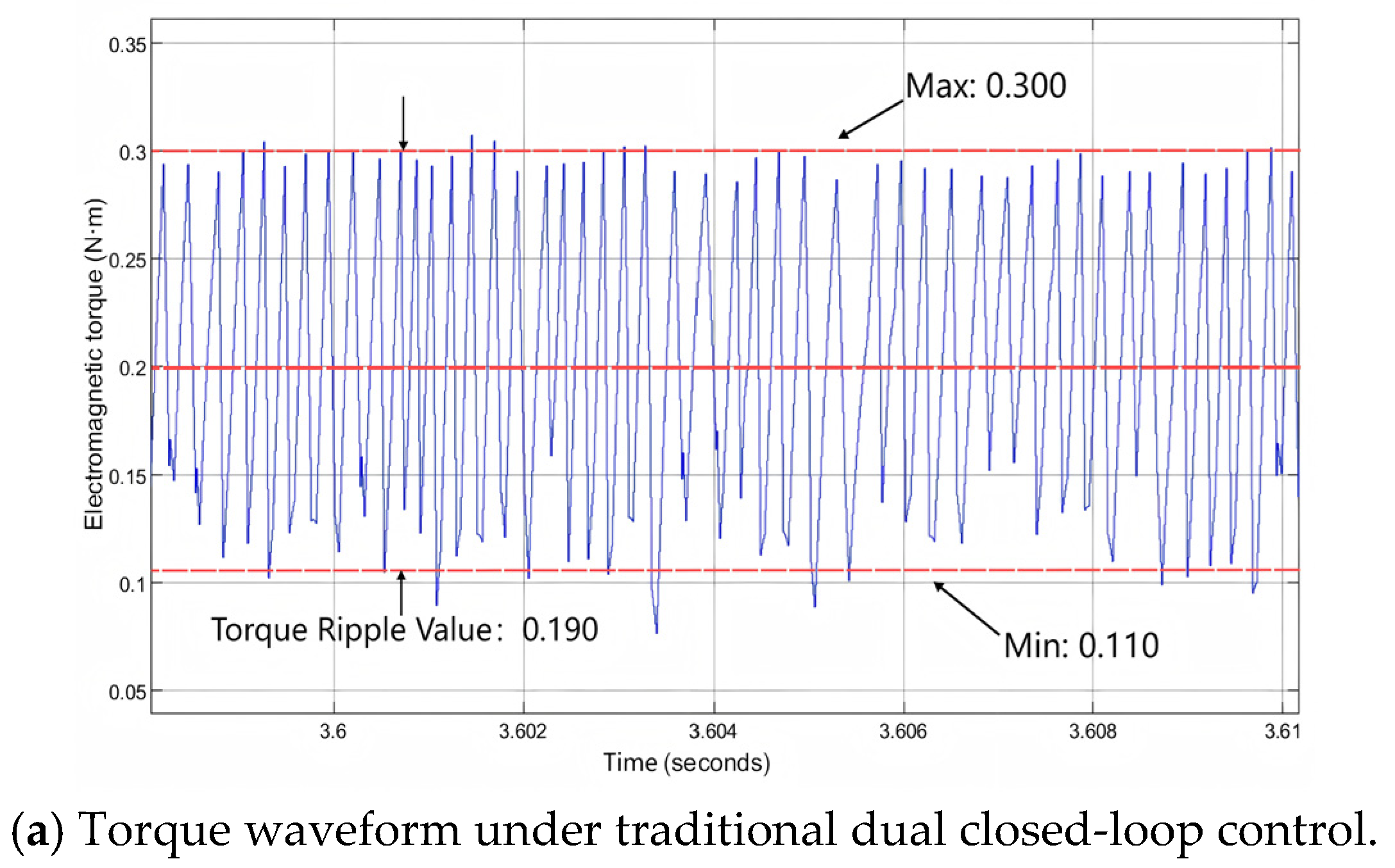
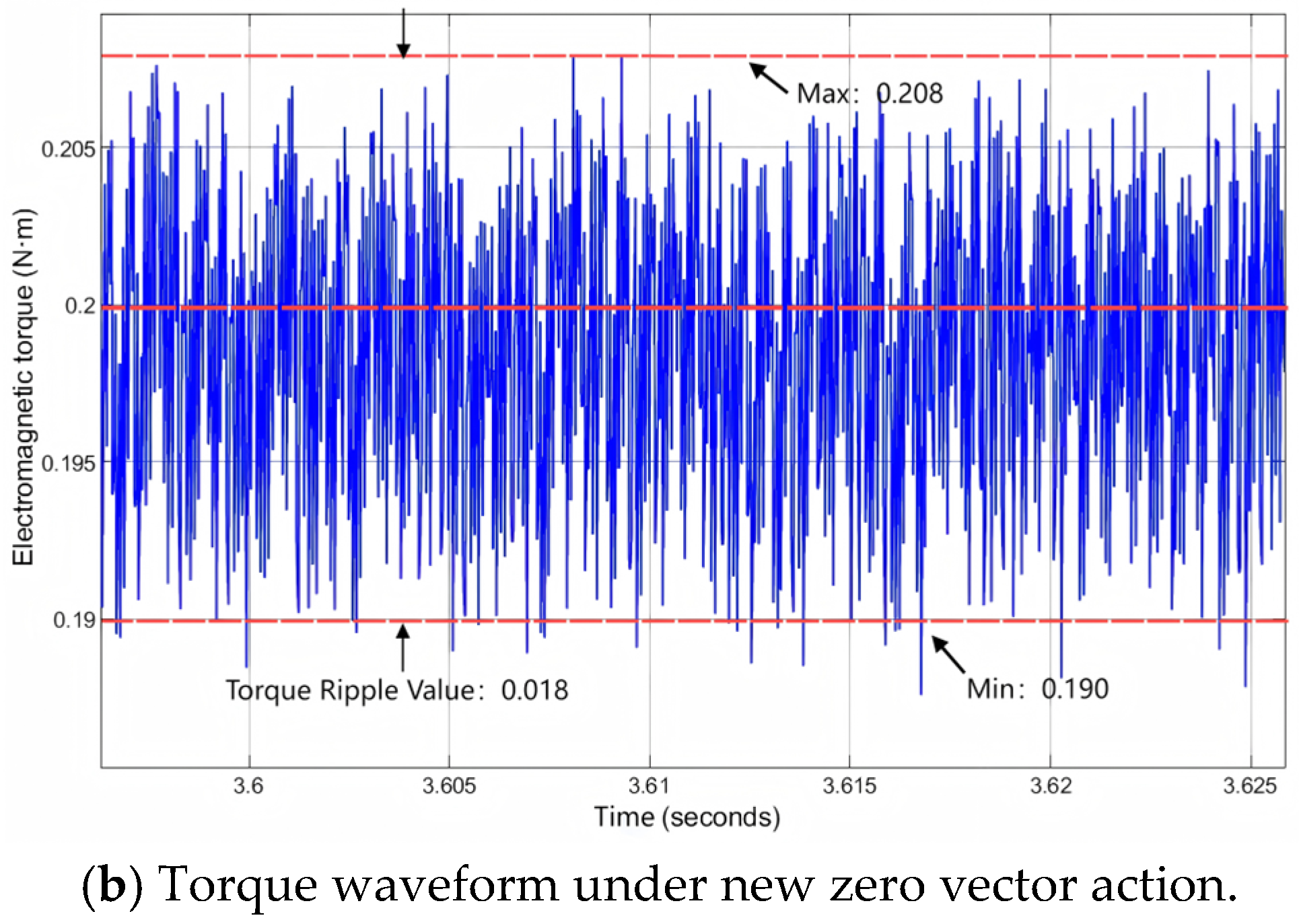
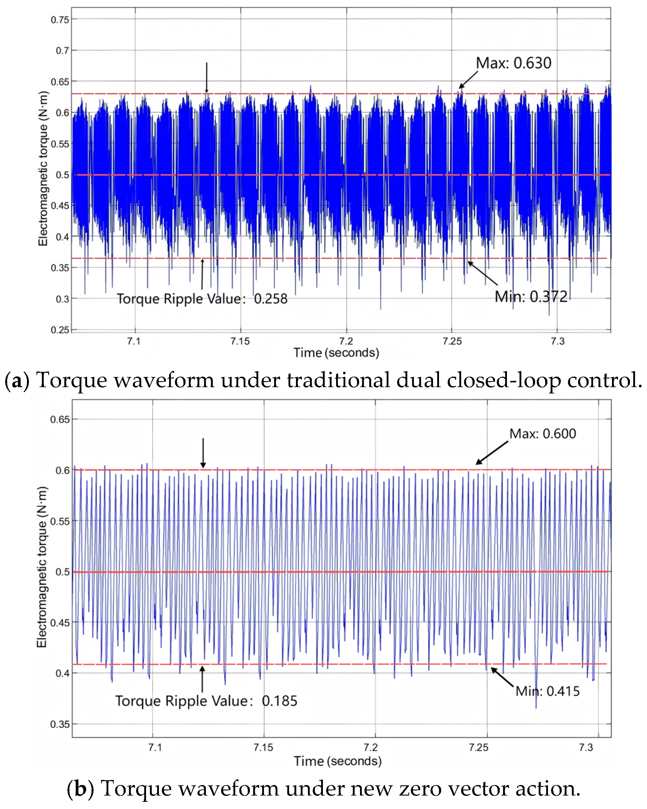
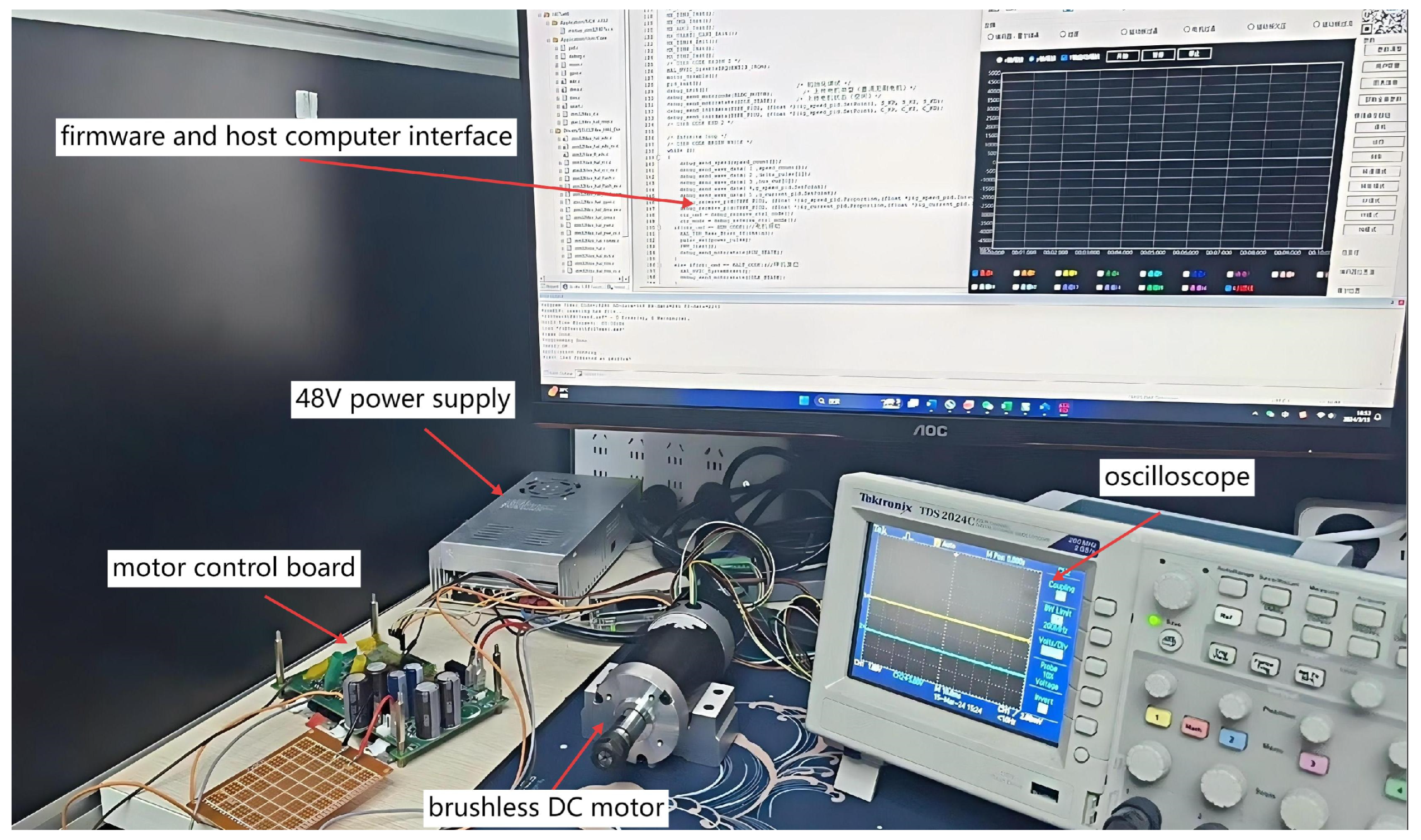
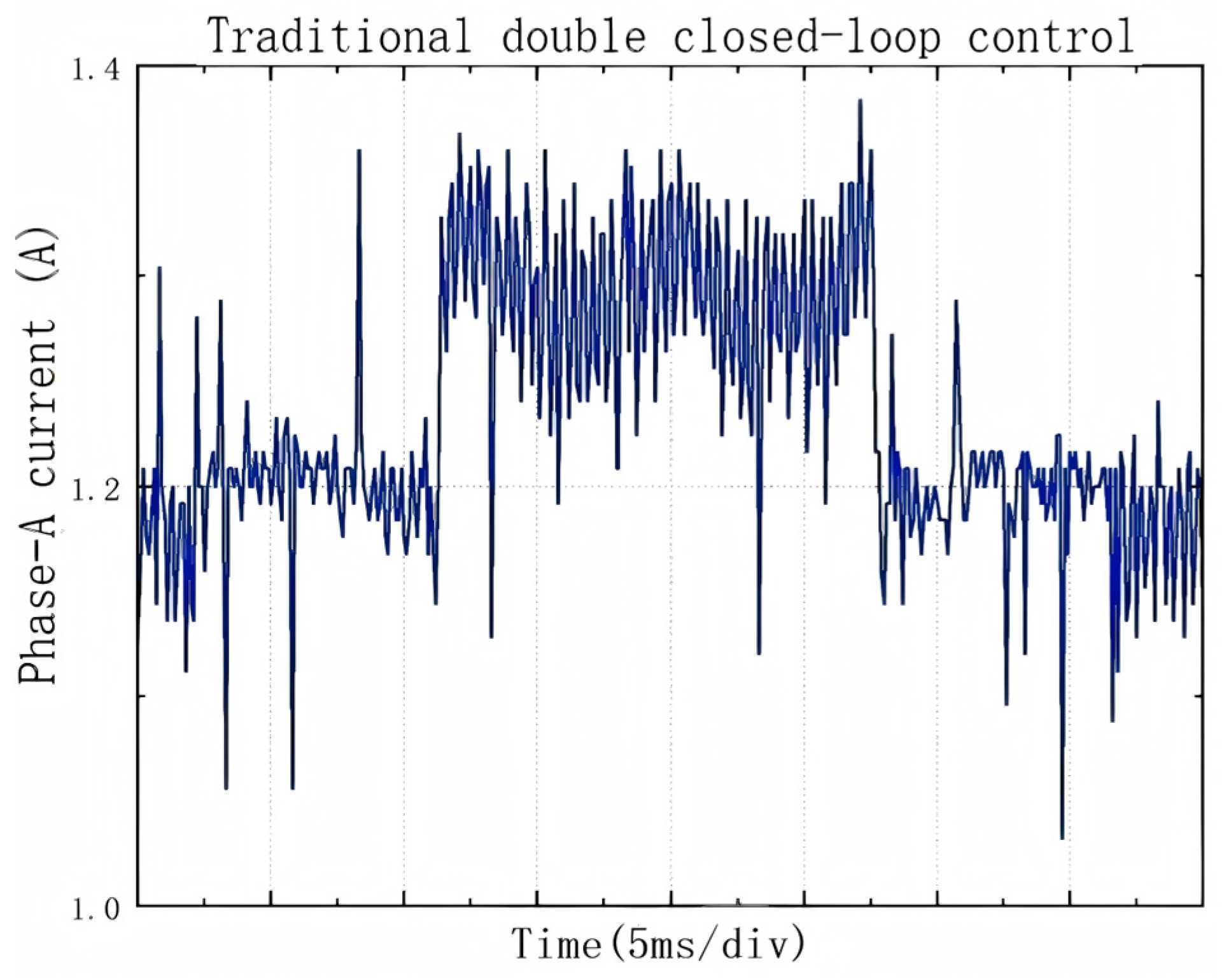
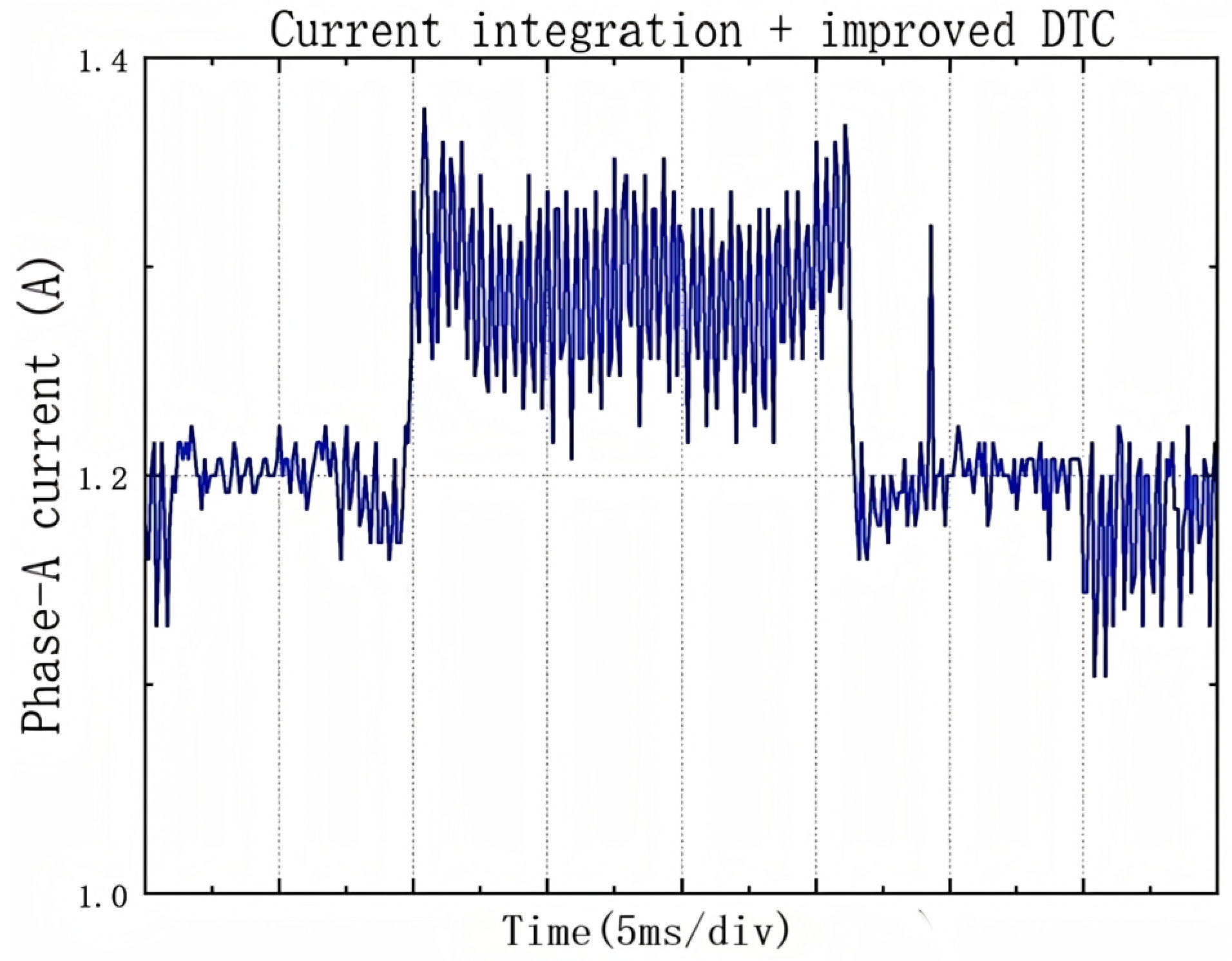
4.2. Experimental Verification

After completing the simulation verification, the proposed algorithm will be integrated into the motor control system, and the corresponding code will be implemented on an STM32-based control board. A physical motor test bench will be constructed using the parameters listed in Table 3, as illustrated in Figure 25.
The motor operation was tested at speeds of 3000 rpm and 7500 rpm under the traditional double closed-loop control method and the new direct torque control method described in this article. The actual measurement results are shown in Figure 26 and Figure 27.
As illustrated in Figure 26 and Figure 27, under operating conditions of 3000 rpm and 7500 rpm the proposed direct torque control strategy—integrating phase current integral-based commutation correction with a novel zero-voltage vector—significantly reduces phase current ripple compared to the conventional dual closed-loop approach. Given the direct correlation between electromagnetic torque and phase current, this reduction in current fluctuation effectively suppresses torque ripple. The close agreement between experimental and simulation results further confirms the feasibility and effectiveness of the proposed control method in enhancing motor stability and dynamic response.

5. Conclusions

This paper systematically investigates the torque ripple issue in BLDCMs. To address the problem of inaccurate commutation, a phase current integration method is introduced to determine the precise commutation timing. Building upon this, the conventional space zero vector is optimized and a novel DTC strategy incorporating a new space voltage zero vector is proposed. The method integrates back-EMF detection and rotor sector identification techniques derived from sensorless control strategies. A complete simulation model and experimental setup are developed to validate the effectiveness of the proposed approach. Simulation and experimental results consistently demonstrate that, under accurate commutation conditions, the proposed method achieves a 58% reduction in torque ripple compared to conventional dual-loop DTC strategies. This confirms both the practicality and performance superiority of the proposed control scheme in sensorless BLDCMs applications.
Future work will focus on extending this strategy to multi-motor coordinated systems and incorporating adaptive algorithms to enhance robustness under parameter variations and external disturbances. Furthermore, real-time implementation on embedded platforms will be explored to evaluate computational efficiency and industrial applicability. Additional studies will also be conducted to assess control performance under extreme operating conditions.

Author Contributions

X.S. undertook the majority of the research work. They implemented the proposed torque ripple suppression strategy based on commutation correction and designed and developed the control algorithm with the integration of a novel zero vector method. They built the simulation model and conducted multiple simulation experiments to validate the effectiveness of the algorithm. They constructed the experimental platform, completed physical experiments, and performed data collection. They analyzed experimental results and prepared figures. They drafted the manuscript and coordinated revisions with all co-authors. H.W. is responsible for the overall design and supervision of the research. They provided funding and key resources, guided the interpretation of the data, contributed to critical revision of the manuscript, and approved the final version for publication. They take full responsibility for the integrity and academic accountability of the work. G.Z. proposed the initial research idea and offered detailed feedback on the manuscript. Z.Z. provided guidance and supervision throughout the research process. Conceptualization, X.S. and G.Z.; Methodology, X.S.; Software, X.S.; Validation, X.S.; Formal analysis, X.S.; Investigation, X.S.; Resources, H.W.; Data curation, X.S.; Writing—Original Draft Preparation, X.S.; Writing—Review And Editing, X.S., H.W. and G.Z.; Visualization, X.S.; Supervision, H.W. and Z.Z.; Project Administration, H.W.; Funding Acquisition, H.W. All authors have read and agreed to the published version of the manuscript.

Funding

This work was supported by the Scientific Research Start-up Fund of North China University of Technology (NCUT) (Fund number: 11005136025XN076-018).

Data Availability Statement

The data supporting the findings of this study are available from the corresponding author upon reasonable request.

Acknowledgments

This study was supported by North China University of Technology.

Conflicts of Interest

The authors declare that they have no relevant financial or non-financial interests, competing interests, or affiliations with any organization that could influence the content of this manuscript.

References

  1. Zhang, H.; Wu, H.; Jin, H.; Li, H. High-Dynamic and Low-Cost Sensorless Control Method of High-Speed Brushless DC Motor. IEEE Trans. Ind. Inform. 2023, 19, 5576–5584. [Google Scholar] [CrossRef]
  2. Çetintaş, O.G.; Akgül, K.; Ergene, L.T. Position Sensorless Speed Control of BLDC Motor with Using Back-EMF Method. In Proceedings of the 2023 14th International Conference on Electrical and Electronics Engineering (ELECO), Bursa, Turkiye, 30 November–2 December 2023; pp. 1–5. [Google Scholar]
  3. Yang, L.; Zhu, Z.Q.; Shuang, B.; Bin, H. Adaptive threshold correction strategy for sensorless high-speed brushless DC drives considering zero-crossing-point deviation. IEEE Trans. Ind. Electron. 2019, 67, 5246–5257. [Google Scholar] [CrossRef]
  4. Chen, X.; Liu, G. Sensorless optimal commutation steady speed control method for a nonideal back-EMF BLDC motor drive system including buck converter. IEEE Trans. Ind. Electron. 2019, 67, 6147–6157. [Google Scholar] [CrossRef]
  5. Padilla-García, E.A.; Cervantes-Culebro, H.; Rodriguez-Angeles, A.; Cruz-Villar, C.A. Selection/control concurrent optimization of BLDC motors for industrial robots. PLoS ONE 2023, 18, e0289717. [Google Scholar] [CrossRef] [PubMed]
  6. Akrami, M.; Jamshidpour, E.; Nahid-Mobarakeh, B.; Pierfederici, S.; Frick, V. Sensorless control methods for BLDC motor drives: A review. IEEE Trans. Transp. Electrif. 2024, 11, 135–152. [Google Scholar] [CrossRef]
  7. Yao, X.; Lin, H.; Zhao, J. Line voltage difference integral method of commutation error adjustment for sensorless brushless DC motor. In Proceedings of the 2018 IEEE Applied Power Electronics Conference and Exposition (APEC), San Antonio, TX, USA, 4–8 March 2018; pp. 843–847. [Google Scholar]
  8. Zhou, X.; Chen, X.; Zeng, F.; Tang, J. Fast commutation instant shift correction method for sensorless coreless BLDC motor based on terminal voltage information. IEEE Trans. Power Electron. 2017, 32, 9460–9472. [Google Scholar] [CrossRef]
  9. Zhao, D.; Wang, X.; Xu, L.; Xia, L.; Huangfu, Y. A New Phase-Delay-Free Commutation Method for BLDC Motors Based on Terminal Voltage. IEEE Trans. Power Electron. 2021, 36, 4971–4976. [Google Scholar] [CrossRef]
  10. Jin, H.; Liu, G.; Zhang, H.; Feng, R. Auto-Correction Commutation Method Based on Phase Voltage Threshold for Position Sensorless Brushless DC Motor. IEEE Trans. Energy Convers. 2024, 39, 1468–1477. [Google Scholar] [CrossRef]
  11. Shi, T.; Li, J.; Cao, Y. Optimal Commutation Error Compensation Strategy for High-Speed Sensorless Brushless DC Motors. IEEE J. Emerg. Sel. Top. Power Electron. 2025, 13, 3411–3425. [Google Scholar] [CrossRef]
  12. Zhou, X.; Chen, X.; Peng, C.; Zhou, Y. High performance nonsalient sensorless BLDC motor control strategy from standstill to high speed. IEEE Trans. Ind. Inform. 2018, 14, 4365–4375. [Google Scholar] [CrossRef]
  13. Wang, L.; Zhu, Z.Q.; Hong, B.; Gong, L. A commutation error compensation strategy for high speed brushless DC drive based on adaline filter. IEEE Trans. Ind. Electron. 2021, 68, 3728–3738. [Google Scholar] [CrossRef]
  14. Guo, J.; Sun, J.; Chen, S. Commutation delay error compensation method for high-speed magnetically levitated BLDC motor based on terminal voltage symmetry. Micro Mot. 2017, 50, 36–42. [Google Scholar]
  15. Zhang, H.; Deng, L.; Jin, H.; Li, H.; Zheng, S.; Zhou, X. Phase Synchronization-Based Commutation Error Correction Method for Position Sensorless Brushless DC Motor. IEEE Trans. Ind. Inform. 2024, 20, 3964–3973. [Google Scholar] [CrossRef]
  16. Zhao, D.; Wang, X.; Tan, B.; Xu, L.; Yuan, C.; Huangfu, Y. Fast Commutation Error Compensation for BLDC Motors Based on Virtual Neutral Voltage. IEEE Trans. Power Electron. 2021, 36, 1259–1263. [Google Scholar] [CrossRef]
  17. Lee, A.-C.; Fan, C.-J.; Chen, G.-H. Current integral method for fine commutation tuning of sensorless brushless DC motor. IEEE Trans. Power Electron. 2017, 32, 9249–9266. [Google Scholar] [CrossRef]
  18. Zhang, H.; Deng, L.; Li, H.; Zheng, S.; Jin, H.; Chen, B. Commutation Point Optimization Method for Sensorless BLdc Motor Control Using Vector Phase Difference of Back EMF and Current. IEEE/ASME Trans. Mechatron. 2024, 29, 423–443. [Google Scholar] [CrossRef]
  19. Li, Y.; Song, X.; Zhou, X.; Huang, Z.; Zheng, S. A Sensorless Commutation Error Correction Method for High-Speed BLDC Motors Based on Phase Current Integration. IEEE Trans. Ind. Inform. 2020, 16, 328–338. [Google Scholar] [CrossRef]
  20. Feng, Z.; Ramesh, R.R.; Tahim, E.S.; Zhang, J.; Ebrahimi, S.; Jatskevich, J. Torque Ripple Reduction in Brushless DC Motors with 180° Commutation. IEEE Trans. Ind. Appl. 2025, 1–14. [Google Scholar] [CrossRef]
  21. El Ouanjli, N.; Derouich, A.; El Ghzizal, A.; Motahhir, S.; Chebabhi, A.; El Mourabit, Y.; Taoussi, M. Modern improvement techniques of direct torque control for induction motor drives—A review. Prot. Control Mod. Power Syst. 2019, 4, 1–12. [Google Scholar] [CrossRef]
  22. Zheng, L.; Liu, J.; Jin, X.; Li, M.; Zhang, Q. Direct Torque Control of Permanent Magnet Synchronous Motor for Reducing Torque Ripple. In Proceedings of the IECON 2023—49th Annual Conference of the IEEE Industrial Electronics Society, Singapore, 16–19 October 2023; pp. 1–6. [Google Scholar] [CrossRef]
  23. Abosh, A.H.; Zhu, Z.Q.; Ren, Y. Reduction of Torque and Flux Ripples in Space Vector Modulation-Based Direct Torque Control of Asymmetric Permanent Magnet Synchronous Machine. IEEE Trans. Power Electron. 2017, 32, 2976–2986. [Google Scholar] [CrossRef]
  24. Kumar, M.S.; Satheesh, G.; Peddakotla, S. Design of optimal PI controller for torque ripple minimization of SVPWM-DTC of BLDC motor. Int. J. Power Electron. Drive Syst. 2023, 14, 283–293. [Google Scholar] [CrossRef]
  25. Nasr, A.; Gu, C.; Wang, X.; Buticchi, G.; Bozhko, S.; Gerada, C. Torque-Performance Improvement for Direct Torque-Controlled PMSM Drives Based on Duty-Ratio Regulation. IEEE Trans. Power Electron. 2022, 37, 749–760. [Google Scholar] [CrossRef]
  26. Khazaee, A.; Zarchi, H.A.; Markadeh, G.A.; Hesar, H.M. MTPA strategy for direct torque control of brushless DC motor drive. IEEE Trans. Ind. Electron. 2020, 68, 6692–6700. [Google Scholar] [CrossRef]
  27. Kim, S.J.; Kim, J.-W.; Park, B.-G.; Lee, D.-H. A Novel Predictive Direct Torque Control Using an Optimized PWM Approach. IEEE Trans. Ind. Appl. 2021, 57, 2537–2546. [Google Scholar] [CrossRef]
Figure 1. Waveform of back electromotive force in an ideal state during phase shift delay.
Electronics 14 02999 g001
Figure 2. Block diagram of direct torque control for BLDCMs.
Electronics 14 02999 g002
Figure 3. Three-value hysteresis comparator control circuit diagram.
Electronics 14 02999 g003
Figure 4. The current during the action of V2 flows into Q6 through Q3.
Electronics 14 02999 g004
Figure 5. The current during the action of V0 flows into Q4 through Q6.
Electronics 14 02999 g005
Figure 6. The process of the new zero vector V60 action.
Electronics 14 02999 g006
Figure 7. New type zero-voltage vector distribution map.
Electronics 14 02999 g007
Figure 8. BLDCMs simulation model.
Electronics 14 02999 g008
Figure 9. Conduction time detection module.
Electronics 14 02999 g009
Figure 10. Simulation block of the current integration module.
Electronics 14 02999 g010
Figure 11. Phase compensation angle calculation module.
Electronics 14 02999 g011
Figure 12. Delay compensation module.
Electronics 14 02999 g012
Figure 13. Rotor sector signal judgment module.
Electronics 14 02999 g013
Figure 14. Three-value torque hysteresis comparator module.
Electronics 14 02999 g014
Figure 15. Sector-voltage vector lookup table module.
Electronics 14 02999 g015
Figure 16. New zero vector lookup table module.
Electronics 14 02999 g016
Figure 17. Phase current distortion waveform.
Electronics 14 02999 g017
Figure 18. Phase current and back-EMF waveforms under commutation advance.
Electronics 14 02999 g018
Figure 19. Phase current and back-EMF waveforms under commutation delay.
Electronics 14 02999 g019
Figure 20. Phase current integral waveform before and after 30° conduction.
Electronics 14 02999 g020
Figure 21. The waveform of phase current and back electromotive force under the effect of phase current integration.
Electronics 14 02999 g021aElectronics 14 02999 g021b
Figure 22. Torque waveform at 5000 rpm.
Electronics 14 02999 g022
Figure 23. Torque waveform at 8000 rpm.
Electronics 14 02999 g023aElectronics 14 02999 g023b
Figure 24. Torque waveform at 12,000 rpm.
Electronics 14 02999 g024
Figure 25. Photograph of the experimental motor test bench.
Electronics 14 02999 g025
Figure 26. Comparison of phase current waveforms at 3000 rpm.
Electronics 14 02999 g026aElectronics 14 02999 g026b
Figure 27. Comparison of phase current waveforms at 7500 rpm.
Electronics 14 02999 g027
Table 1. Three-value hysteresis comparator voltage vector selection table.
SectorτVoltage Vector
(Counterclockwise)
Voltage Vector
(Clockwise)
I1 V 2 ( 001001 ) V 5 ( 000110 )
0 V 0 ( 000000 ) V 0 ( 000000 )
−1 V 5 ( 000110 ) V 2 ( 001001 )
II1 V 3 ( 011000 ) V 6 ( 100100 )
0 V 0 ( 000000 ) V 0 ( 000000 )
−1 V 6 ( 100100 ) V 3 ( 011000 )
III1 V 4 ( 010010 ) V 1 ( 100001 )
0 V 0 ( 000000 ) V 0 ( 000000 )
−1 V 1 ( 100001 ) V 4 ( 010010 )
IV1 V 5 ( 000110 ) V 2 ( 001001 )
0 V 0 ( 000000 ) V 0 ( 000000 )
−1 V 2 ( 001001 ) V 5 ( 000110 )
V1 V 6 ( 100100 ) V 3 ( 011000 )
0 V 0 ( 000000 ) V 0 ( 000000 )
−1 V 3 ( 011000 ) V 6 ( 100100 )
VI1 V 1 ( 100001 ) V 4 ( 010010 )
0 V 0 ( 000000 ) V 0 ( 000000 )
−1 V 4 ( 010010 ) V 1 ( 100001 )
Table 2. New zero vector voltage vector selection table for three-value hysteresis comparator.
SectorτVoltage Vector
(Counterclockwise)
Voltage Vector
(Clockwise)
I1 V 2 ( 001001 ) V 5 ( 000110 )
0 V 60 ( 000101 ) V 60 ( 000101 )
−1 V 5 ( 000110 ) V 2 ( 001001 )
II1 V 3 ( 011000 ) V 6 ( 100100 )
0 V 10 ( 101000 ) V 10 ( 101000 )
−1 V 6 ( 100100 ) V 3 ( 011000 )
III1 V 4 ( 010010 ) V 1 ( 100001 )
0 V 20 ( 010001 ) V 20 ( 010001 )
−1 V 1 ( 100001 ) V 4 ( 010010 )
IV1 V 5 ( 000110 ) V 2 ( 001001 )
0 V 30 ( 001010 ) V 30 ( 001010 )
−1 V 2 ( 001001 ) V 5 ( 000110 )
V1 V 6 ( 100100 ) V 3 ( 011000 )
0 V 40 ( 010100 ) V 40 ( 010100 )
−1 V 3 ( 011000 ) V 6 ( 100100 )
VI1 V 1 ( 100001 ) V 4 ( 010010 )
0 V 50 ( 100010 ) V 50 ( 100010 )
−1 V 4 ( 010010 ) V 1 ( 100001 )
Table 3. BLDCMs parameters.
ParametersUnitValue
Stator phase resistance Ω 0.24
Stator phase inductance H 4.673 × 10 4
Moment of inertia kg m 2 0.00103
Back electromotive force constant V / k r p m 2.93
Rated torque N m 0.6
Number of pole pairs / 2
Rated speed r / min 12 , 000
DC voltage V 48
Disclaimer/Publisher’s Note: The statements, opinions and data contained in all publications are solely those of the individual author(s) and contributor(s) and not of MDPI and/or the editor(s). MDPI and/or the editor(s) disclaim responsibility for any injury to people or property resulting from any ideas, methods, instructions or products referred to in the content.

