1. Introduction
With the continuous development of the Internet of Vehicles (IoV), integrated sensing and communication (ISAC) technology has garnered significant attention, highlighting its growing importance in assisting vehicular communication. Among various enabling technologies, reconfigurable intelligent surfaces (RISs) have emerged as a promising solution because of their ability to enhance signal transmission flexibly. By dynamically controlling the propagation of electromagnetic waves, RISs can achieve broader coverage and improved beamforming capabilities, making it a key technology for 6G-enabled vehicular networks [
1,
2,
3]. In particular, hybrid RISs, which integrate both active and passive reflective elements, offer additional flexibility and efficiency in complex communication environments, providing crucial technological support for the development of smart cities and intelligent transportation systems [
4,
5,
6].
Many scholars have conducted extensive research on RIS technology. For example, Wu et al. explored the use of RISs to reconfigure wireless environments to enhance communication efficiency [
7]. Nemati et al. investigated the advantages of RISs in improving coverage in millimeter-wave cellular networks [
8]. Furthermore, in the context of integrating RISs with MIMO systems to enhance vehicular network performance, Chen et al. focused on QoS-driven spectrum-sharing strategies for RIS-assisted vehicular networks, providing both theoretical and practical foundations for the application of RISs in vehicular communications [
9].
Moreover, the application of RIS technology has substantially improved localization accuracy, enabling more precise position and direction estimation, which is crucial for vehicular network applications [
10]. The combination of RIS technology with wireless energy harvesting networks through backscatter communication has demonstrated outstanding potential for energy-efficient communications [
11]. Furthermore, an innovative dual-RIS architecture has been proposed to optimize MIMO communication systems under line-of-sight (LoS) conditions, significantly enhancing system capacity and scalability [
12].
Recent studies have further explored the challenges and applications of RIS technology. Research has focused on the integration of RISs into vehicular communication networks (V2X), optimizing resource allocation, and addressing trust and interference issues in dense vehicular networks [
13]. The application of hybrid RIS-assisted communication systems in device-to-device (D2D) communications has also gained attention, where performance is further enhanced through active element selection algorithms [
14].
Performance analysis of Large Intelligent Surface (LIS) technology has demonstrated its significant advantages in terms of asymptotic data rates and channel stability [
15]. In RIS-assisted multi-user MIMO downlink communication, beamforming optimization techniques have shown great potential in mitigating interference and improving communication quality [
16]. Meanwhile, researchers have developed more advanced channel estimation techniques, such as a two-stage channel estimation method considering the Doppler effect, which significantly enhances estimation accuracy in hybrid RIS-assisted MIMO systems [
17,
18]. Moreover, RIS-specific hardware architectures that utilize a minimal number of active elements have been proposed to facilitate more efficient channel estimation processes and improve overall system performance [
19,
20,
21]. Lastly, the prospects of intelligent reflecting radio technology have been further emphasized, underscoring its potential in future wireless environments [
13,
22,
23,
24,
25].
In the field of vehicular networks, the rapid growth of connected devices and mobile services has led to increasingly congested spectrum resources. High-frequency signal transmission suffers from significant path loss, and non-line-of-sight (NLOS) paths are typically weak, while line-of-sight (LOS) paths are prone to blockage by environmental objects [
26,
27]. As a result, the performance of ISAC systems is highly dependent on the propagation environment, leading to coverage limitations and multiple blind spots. RIS technology offers a promising solution by enabling programmable control over incident signals, including amplitude, phase, polarization, focusing, and attenuation. By intelligently shaping the spatial electromagnetic environment and optimizing signal transmission paths, RISs can mitigate inter-user interference, enhance coverage, and improve spectral and energy efficiency, effectively addressing key challenges in ISAC systems [
28]. However, in active RIS-assisted communication systems, the complexity and variability of external environments, along with the noise generated by active RIS elements, can significantly degrade communication link quality, ultimately reducing system performance [
29,
30,
31].
To tackle this issue, this study aims to develop a hybrid RIS adaptive resource allocation framework specifically designed for ISAC-enabled vehicular networks. The proposed framework optimizes RIS phase configuration and beamforming strategies to minimize multi-user interference (MUI), thereby maximizing communication efficiency and reliability. The findings of this study provide a theoretical foundation for deploying RIS technology in next-generation 6G vehicular networks, addressing critical challenges related to communication reliability and efficiency. To this end, a joint optimization algorithm based on a Twin Delayed Deep Deterministic Policy Gradient (TDDPG) is proposed. This optimization problem considers both communication performance and sensing accuracy while adhering to practical constraints such as total power budget, RIS noise power limitations, and Cramér–Rao Lower Bound (CRLB) constraints. The main contributions of this paper are as follows:
TDDPG-Based Joint Optimization Framework: A novel TDDPG-based algorithm is designed to jointly optimize the transmit beamforming and RIS phase shift matrix. Two coordinated DDPG agents are employed to handle the coupling between communication and sensing tasks. By sharing a unified reward function that incorporates multi-user interference (MUI), total power constraints, and the Cramér–Rao Lower Bound (CRLB) for sensing, the framework ensures balanced performance improvements in both communication and radar functionalities.
Hybrid RIS Architecture for Efficiency–Performance Tradeoff: This work adopts a hybrid RIS architecture combining active and passive elements to improve energy efficiency and reduce hardware complexity. The proposed system can dynamically adjust the proportion of active RIS units to achieve a balance between communication performance and cost, making it suitable for real-world vehicular scenarios.
Robustness in Dynamic Vehicular Environments: The TDDPG algorithm demonstrates faster convergence and better adaptability compared to conventional DDPG methods, especially in dynamic and interference-rich environments. Simulation results confirm that the proposed method achieves lower average MUI and higher communication sum rates while also meeting radar sensing constraints under varying network conditions.
The remainder of this paper is organized as follows:
Section 2 provides an overview of the system model and problem formulation.
Section 3 introduces the design and solution of the hybrid RIS-assisted ISAC optimization problem based on the Twin Delayed Deep Deterministic Policy Gradient (TDDPG) algorithm.
Section 4 presents the experimental results and analysis. Finally,
Section 5 concludes the study and discusses potential future research directions.
2. System Model and Problem Formulation
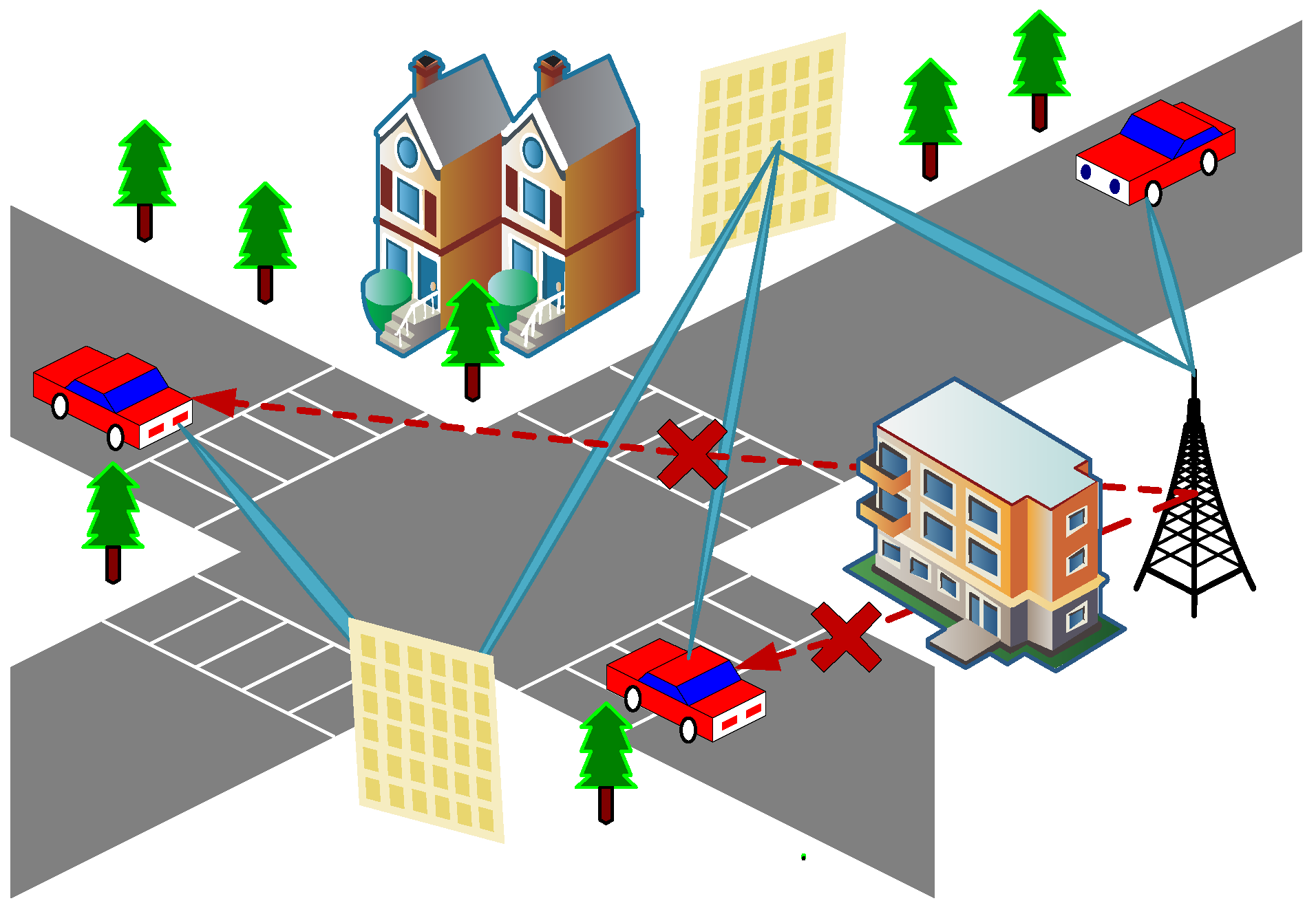
In this paper, we consider the hybrid RIS-assisted IoV ISAC scenario, as shown in
Figure 1. The direct links between the Dual-Functional Base Station (DFBS) and
U targets are blocked by multiple buildings. To overcome this problem, two hybrid RISs are deployed around the building in this scenario to establish a multi-reflection signal transmission path between the DFBS and the target. In addition, the hybrid RIS controller can intelligently adjust the phase shift of the reflected signal, which in turn optimizes the communication quality to ensure accurate and efficient information transmission.
In this paper, we consider the downlink transmission link from DFBS to the target vehicle. Let
and
denote the discrete-time complex baseband signals for communication and radar sensing, respectively. Assuming that these signals are uncorrelated with each other and that the power magnitude is unit power, DFBS precodes
c using the communication beamformer
and precodes
r using the sensing beamformer
, and then the overall downlink transmitted signal
is the superposition of the communication and radar signals, denoted by
and the corresponding transmission covariance matrix is denoted as
, and this signal reaches the target vehicle through the reflection of the hybrid RIS.
In this paper, we consider the deployment of a square hybrid RIS with
M elements, where
denotes the RIS coefficient. Without loss of generality, this paper assumes that the first
K reflecting cells of the RIS are active and their maximum amplifier gain is
. In this paper, the index sets of active and passive reflection units are denoted as
and
, respectively. Thus, when
, we get
; when
, we get
. Let
denote the selection matrix of the identity matrix before
K rows and
denote the selection matrix of the identity matrix after
rows. When the input signal is
, the output of the hybrid RIS is
where
n is the RIS noise caused by the active component. Furthermore, the total output power of the active reflecting element can be expressed as
In the multi-reflection signal path model, this paper considers the presence of two mixed RISs, and the reflection amplitude is set to 1 to maximize the power of the RIS reflected signal so as to facilitate hardware implementation.
Let , , and be the channel matrix models from the base station to RIS 1, from RIS 1 to RIS 2, and from RIS 2 to the target vehicle. Only the LoS channel between adjacent nodes is considered in the model, and the LoS channel is modeled as the product of the array responses on both sides. For ULA at DFBS, the array response is denoted as , where T is the number of antennas, is the normalized antenna spacing, is the carrier wavelength, and represents the azimuth angle of the Angle of Departure (AOD) from DFBS to RIS 1. The array response at each hybrid RIS is denoted by , where and denote its Angle of Arrival (AOA) and azimuth and elevation angles of the AOD, respectively, and d is the reflector element spacing. Therefore, according to the position of the target vehicle, define and as the azimuth and elevation angles of the AOA from DFBS to RIS 1, define and as the azimuth and elevation angles of the AOD from RIS 1 to RIS 2, and define and as the azimuth and elevation angles of the AOA from RIS 1 to RIS 2. Define and as the azimuth and elevation angles of the AOD from RIS 2 to the target vehicle u.
Let
denote the distance from BS to RIS 1,
the distance from RIS 1 to RIS 2, and
the distance from RIS 2 to the target vehicle. We assume that in the vehicle ISAC system based on RIS,
H represents the wireless channel response matrix between different nodes (base station, RIS, vehicle). Specifically,
H describes the propagation gain and phase offset of the line-of-sight (LoS) link between each pair of nodes, which is modeled as the product of the transmit and receive array response vectors.
Y represents the signal matrix received by the target vehicle, reflecting the result of signal transmission through the RIS-assisted channel. Specifically,
Y contains the symbols to be transmitted, interference, and noise. Then, the channel
from BS to RIS 1 is denoted by
where
represents the LoS path gain at a reference distance of 1 m. The channel
from RIS 1 to RIS 2 is denoted by
The channel
from RIS 2 to the target vehicle is denoted by
According to the above channel expression, the output signal at RIS 1 can be expressed as
The output signal at RIS 2 can be expressed as
By expressing the desired symbol matrix at the target vehicle as
, the received signal matrix can be rewritten as
where
represents the noise at the target vehicle and the second term represents the multi-user interference (MUI). Then, the total energy of the MUI can be expressed as
The SINR of the
u-th user can be expressed as
where
denotes the
u-th row of
and
denotes the expectation. Then, the achievable sum rate of the system can be expressed as
The above equation shows that the achievable data rate of user
u can be maximized by minimizing the received interference of user
u, so minimizing the MUI energy is closely related to maximizing the sum rate. Meanwhile, the MUI energy is also closely related to the MSE between the received signal and the desired signal. The MSE is defined as
Therefore, this paper optimizes the sum rate and MUI of the communication system by maximizing the MSE.
For radar systems, a fundamental function is to estimate the AOD of the target. In this paper, radar is considered to estimate the AOD of a target located at Angle
. The signal received by the radar can be expressed as
where
is the reflection coefficient of the target, the Radar Cross Section (RCS), and
is the antenna steering vector.
is the Additive White Gaussian Noise (AWGN) with zero mean and covariance matrix
.
Therefore, the parameters to be estimated for the received signals can be expressed as
The Fisher information matrix (
) of it has been calculated as [
32]
where
,
, and
denotes the derivative of the steering vector, which can be expressed as
, where
denotes the
i-th element of
.
The Cramér–Rao Lower Bound (CRLB) is one of the determinants of the performance of radar communication systems, which can provide a lower bound for MSE. Then, when the target is located at direction
, the CRLB of the arrival angle is
, which can be expressed as
To accurately estimate the AOD of the target, the CRLB needs to be less than A given threshold
:
Let
. Then, Equation (
18) can be rewritten as
3. Design and Solution of ISAC Optimization Problem Assisted by Hybrid RIS in Internet of Vehicles
The use of active components in the RIS results in additional noise when the RIS output signal is transmitted to the target vehicle, which adversely affects the radar and communication SNR. In this paper, the optimal value of the phase shift of each RIS calculated by the base station is sent to the intelligent controller of the RIS under the constraints of total transmit power, RIS noise power, and CRLB of signal arrival estimation. At the same time, an appropriate beamformer is selected to minimize the MSE of system communication while ensuring the minimum SNR of communication to suppress RIS noise. The optimization problem can be formulated as
where
represents the
-th element of
, constraint
constricts the ISAC waveform to constant modulus,
is the total transmit power constraint at DFBS,
is the total power constraint at RIS, and
is the CRLB constraint to accurately estimate the target AOD.
To cope with the tight coupling between beamforming and RIS phase shift matrix design in RIS-assisted communication, this paper proposes a novel joint optimization method based on the TDDPG architecture. Two DDPG structures are cleverly employed in the TDDPG structure, one of which is responsible for the output RIS phase shift, and the other is focused on the generation of the joint beamforming vector. Such a design aims to effectively decouple the design process of the RIS phase shift and the joint beamforming vector and simplify the optimization task. In addition, the two DDPG architectures work together by sharing a common reward function, which can guide the agent to adjust the policy of its output action, ensuring that the output RIS phase shift and beamforming vector can significantly reduce the MSE of the system, thereby improving the communication performance.
3.1. DDPG Method
Traditional RL methods perform well when dealing with tasks with small and discrete action and sample spaces. However, traditional RL methods often struggle to cope with complex tasks such as RIS-assisted UAV communication, especially when the state space is huge and the action space is continuous, especially when the input data consists of high-dimensional images. In order to solve this problem, the DeepMind team introduced DQN, which uses a Deep Neural Network (DNN) to approximate the Q-value function in Q-learning, combining the advantages of deep learning and reinforcement learning. The DDPG algorithm is further innovative on the basis of DQN, which combines the deterministic policy gradient (PG) algorithm and the experience replay pool and target network technology in DQN. DDPG adopts the Actor–Critic architecture, which can directly output deterministic actions, successfully solves the continuous control problem, and makes the DRL method better adapted to the needs of the wireless communication field.
In a single DDPG algorithm, four neural networks are employed to model different functions. Specifically, Actor network is a parameterized network that is responsible for expressing behavior policies; the network of the Critic, however, is another parameterized network that predicts the long-term reward obtained by taking a particular action in the current state, the Q-value. In addition, to cope with the possible bootstrapping problem during the parameter update process, the concept of the target network is introduced. Among them, the Target Actor network and the Target Critic network are copies of the Actor network and the Critic network, respectively. Their existence helps to stabilize the learning process and prevent the network from violent oscillation during the training process, so as to ensure the smooth progress of the learning process.
First, the agent takes state from the environment and executes the action produced by the Actor network; then, it obtains an immediate reward and moves on to the next state . The experience tuple is stored in the experience replay buffer D, and samples with batch size are randomly selected to train the neural network.
The output of the Actor network is the action performed by the agent. During the training process, the parameters of the Actor network are updated to maximize the cumulative expected reward by gradient ascent, which uses the Adam optimizer to update
. Specifically, the parameters of the Actor network are updated according to the gradient calculation formula. Given that the DDPG algorithm involves drawing samples from a pool of experience replay, a Monte Carlo method is used to compute the policy gradient. Therefore, the Actor network is trained and updated with parameters by the following policy gradient function, which continuously optimizes its behavior policy:
where the performance objective function
J is designed for the offline policy learning scenario, which can quantitatively evaluate the policy, measure the performance of a policy, and guide the parameter update process of the Actor network to optimize the behavior of the agent. The function is defined as follows:
where
s is the state of the environment and
is the probability distribution function based on the state generated by policy
.
is the value of Q resulting from choosing an action according to policy
at each state
s. The update of the q-value satisfies the Bellman equation, which is expressed as follows:
This formula describes the Q-value of taking an action a in a given state s, which is the sum of the immediate reward r and the reward for taking an action that leads to the optimal long-term future reward, where the future reward is partially adjusted by a discount factor . The discount factor captures the degree of importance of possible future rewards relative to current rewards, and it determines the consideration of the trade-off between future and current rewards in the decision-making process.
In the DDPG algorithm, the experience replay mechanism plays a crucial role. This mechanism builds a memory to store the four-tuple data generated by each state transition. During training, the algorithm randomly draws samples from the experience replay pool, which are used to update the network parameters. This random selection method ensures the independence between samples, effectively breaks the correlation between samples, and improves the stability and convergence speed of the algorithm.
The network of the Critic is used to fit
and output the Q-value for performing action
a in a given state
s. The update of the network parameters
of the Critic is achieved by minimizing the error between the evaluation value
and the target. Here, the error
can be expressed as follows:
where
can be viewed as the target Q-value and its expression is
The is obtained by calculating the Target Actor network and the Target Critic network . This practice makes the Critic network more stable in the process of parameter learning by introducing the target network so that it is easier to converge. This design effectively improves the robustness and learning efficiency of the algorithm.
In the DDPG method, the target network adopts the strategy of soft updates. This soft update method ensures the smooth change in the target network parameters so that the target value calculated by the target network is more stable. This stability is crucial in the learning process of the Critic network. Let the learning rate in the target network update process be
; then, the parameter update process of the target network can be carried out in the following way so as to realize the smooth transition of parameters and the stability of learning:
3.2. TDDPG Method
According to the aforementioned DDPG network architecture and parameter update mechanism, this chapter adopts a novel TDDPG structure. Among them, the first DDPG is specifically responsible for learning the optimization strategy of the RIS phase shift matrix. To reduce the MSE of the system communication, the first DDPG defines the relevant elements, that is, the state , the action , and the reward function in the n-th time interval as follows, respectively:
- 1.
State : The first DDPG is used for RIS phase shift matrix optimization, and the position information of the target vehicle will be used as the state input of this network;
- 2.
Behavior : This represents the action output by this network, which is the phase shift change in the RIS in the next time interval;
- 3.
Reward
: The reward function
is used as a judgment on the behavior of the agent, and its construction directly determines the quality of the training results. The reward function is constructed as follows:
where
,
, and
are the penalty terms when the constraints
,
, and
are not satisfied and
,
, and
are the weight coefficients corresponding to each penalty term, respectively.
In terms of the influence of the p parameter on the function, when the reward signal is linear, there can be a relatively constant limiting force for actions that exceed the constraints. This enables the agent to be forced away from the incorrect strategy early on, and during the learning process, it is manifested as the violation of constraints in the early training period rapidly decreasing. When the reward signal is quadratic or logarithmic, during the learning process, it is manifested as being more likely to approach the optimal boundary value in the middle and later stages of training, but in the early stage, it is prone to causing jitter in the Actor.
In the simulation of
Section 4 of this article, the value of the parameter
p is determined by the following formula:
To ensure the stability of the training process, the value of the q parameter is usually determined based on experience. Regarding the influence of the q parameter on the function, when q is small, the agent will prioritize maximizing the long-term reward accumulated from optimizing the task, while there will be some relaxation in the constraints, manifested as the transmission power occasionally exceeding the threshold condition, resulting in increased energy consumption or inter-base station interference problems; when q is large, the agent will strictly satisfy the constraints, but in terms of learning speed, it will lag behind the situation with a lower q value, causing a problem of slow convergence, manifested as the communication rate of the system will decrease. One study may prioritize power constraints, while another study may prioritize perception accuracy. Therefore, in different scenarios, different values of q are generally selected based on the core task.
The second DDPG module in the TDDPG structure will be used for beamforming optimization. This module will output the beamforming vector at the transmitter in a given state. The state , action , and reward of the second DDPG at the -th time interval are defined as follows:
- 1.
State : The cascaded channel will be the state input of the second DDPG;
- 2.
Behavior : The behavior of the second DDPG output will be defined by the beamforming vector at the transmitter;
- 3.
Reward
: Since the purpose of the TDDPG algorithm adopted in this paper is to jointly optimize the beamforming matrix at the transmitter and the RIS phase shift coefficient to minimize the system communication MSE, the second DDPG module shares the same reward function with the first DDPG module, that is, the reward function in Equation (
28), so as to improve the communication efficiency.
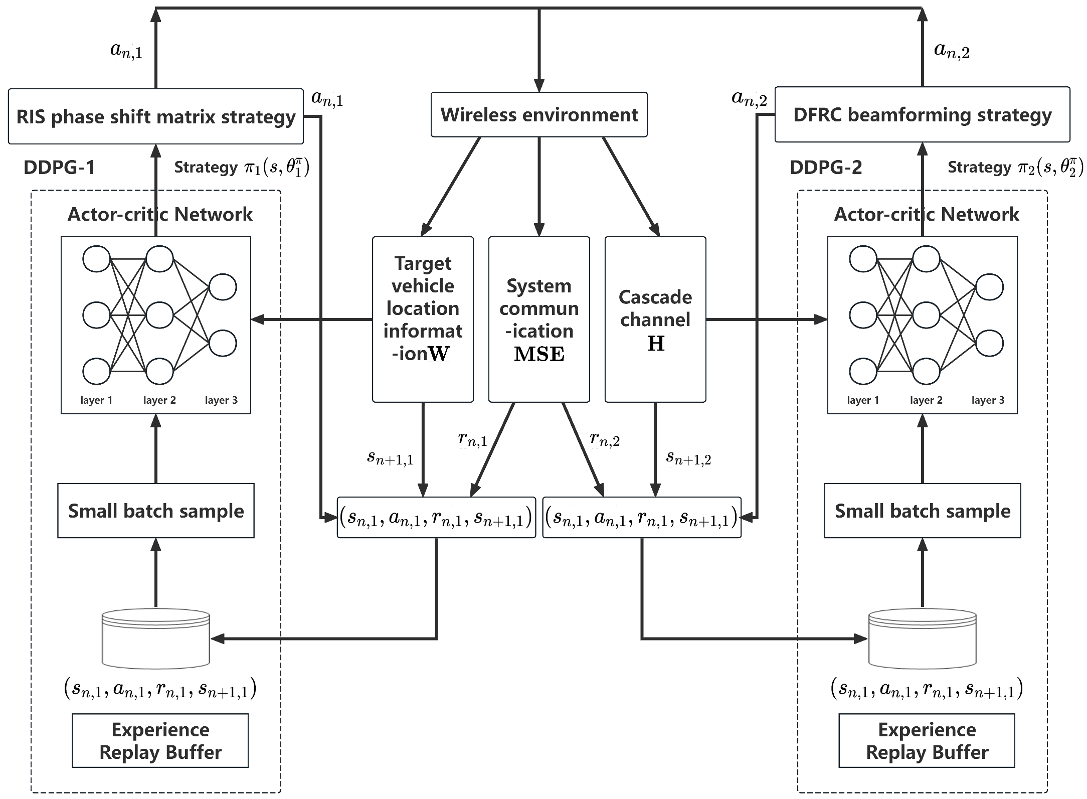
The structure of the TDDPG algorithm is shown in
Figure 2 as follow.
The procedure of the TDDPG algorithm is shown in Algorithm 1.
| Algorithm 1: TDDPG algorithm |
- 1:
Initialization: Initializing Actor network , Critic network , Target Actor network , and Target Critic network of the first DDPG in TDDPG; Initializing Actor network , Critic network , Target Actor network , and Target Critic network of the second DDPG in TDDPG; - 2:
for
do - 3:
Reset the RIS phase shift matrix and the target vehicle position; - 4:
for do - 5:
The location of the target vehicle is set as state , and the cascade channel is set as state . - 6:
Select the corresponding actions and . - 7:
Calculate the immediate rewards and for taking actions and according to Equation ( 27); - 8:
Calculate the transition states and ; - 9:
The state transition data and are stored in the experience replay pool ; - 10:
Take state transition data from experience replay pool and update , , , ; - 11:
Update , , , ; - 12:
end for - 13:
end for
|
The TDDPG algorithm proposed in this chapter inputs the position information and the cascade channel into the DDPG network as two independent states so that the algorithm could output the RIS phase shift matrix and the beamforming strategy, respectively, to successfully decompose the complex optimization problem into two independent sub-problems for solving. In this process, the TDDPG realizes the cooperation of two DDPG agents by introducing a shared reward function and wireless environment information, and each agent learns and optimizes the phase shift matrix and beamforming strategy to better cope with the dynamic changes in the wireless environment and achieve more accurate and efficient optimization effects.
3.3. Analysis of Algorithm Convergence and Expansion
In this subsection, we examine the engineering feasibility of the TDDPG algorithm proposed in this paper. The number of floating-point operations required for each execution of the TDDPG algorithm can be expressed as
where
is the length of the state vector,
is the length of the action vector,
H is the number of units in each hidden layer, and
L is the number of hidden layers. Therefore, the time complexity of this algorithm is
, and the number of floating-point operations required for each update is approximately
. Assuming that a computing platform with a computing power of 1
is deployed at the base station, the time required for one calculation is approximately 0.8
. This can fully meet the performance requirements of a scenario with a vehicle speed of 120
and a coherence time of 3–5
between RIS-BS links, and it has practical significance for engineering deployment.
This algorithm can also be extended to scenarios with higher user density and random mobility models. The original state
only contains the geometric and channel information of a single user’s straight-line path. For a large number
U of random trajectories of users in complex scenarios, the original state can be rewritten as
where
represents the user’s position,
represents the user’s movement state, and
H represents the channel state.
Update the multi-user interference power to
For the TDDPG algorithm, the network structure does not need to be modified. As the number of users increases, simply increasing the width of the hidden layers can enable the algorithm to be extended to more complex scenarios.
4. Simulation Results and Analysis
To verify the effectiveness of the proposed model and the joint optimization algorithm based on the TDDPG architecture, a IoV scenario is considered in this section, where the DFBS equipped with antennas is located at and the initial positions of the target users are set to , , , and move in a straight line along the x-axis direction. The two hybrid RIS locations are set to and .
For the direct base station–vehicle link, we consider it as an NLoS link. During the optimization process, we basically ignore the direct NLoS channel between the base station and the vehicle, which is equivalent to saying that it is in a deep fading state. If we want to simulate this direct connection, we will set it as Rayleigh fading with extremely low average power. In fact, this means that the channel coefficient between the base station and the user equipment can be derived from a Gaussian random variable with a mean of 0 and a variance of , and is determined by the large-scale path loss of the NLoS path. Since in the Rayleigh scenario, the average gain of the direct connection is low, the strategy will naturally continue to rely on the RIS path with higher and more stable gains, that is, the strategy automatically excludes the unreliable direct path and focuses on the channel with a stronger deterministic component. Therefore, the consideration of Rayleigh fading under the NLoS path will not affect the convergence result of the algorithm. In the simulation analysis, we use the ideal LoS channel between the station–vehicle and station–station.
In terms of algorithm design, the proposed TDDPG algorithm was compared with the DDPG algorithm, where each DDPG framework deployed two fully connected hidden layers with 20 neurons in the original network and the target network, respectively. The main simulation parameters settings are shown in the
Table 1 below.
When optimizing the simulation and learning environment, we adopted a two-stage strategy that balanced theoretical requirements and empirical verification. Firstly, based on the typical hardware conditions of the vehicle networking system, we determined the system-level limitations and adopted a RIS array. Then, 10 active RISs were mixed into this array. This choice balanced performance and system complexity well. Increasing the number of array units brought a much smaller performance gain than the deployment cost. The upper limit of base station transmission power , the maximum total transmission power of RIS end , path gain (large-scale fading) , and noise power were all selected as commonly used engineering values. The CRLB threshold was set to 0.01, which is a typical level of vehicle-grade radar, meaning the angle estimation error is less than approximately 5.7°. In terms of training parameters, the size of the back buffer was selected as 1600, which retained sufficient sample quantities while shortening the calculation time. The step size was chosen as 50 in a single step because in the simulation process, choosing a shorter step size would cause severe fluctuations in the training rewards, while choosing a longer step size would lead to large gradient deviations and drift in the update direction. During the Actor–Critic update process, a mini-batch training with 32 per batch was adopted to achieve the best balance between gradient stability and computational load. This parameter was obtained through empirical methods. The number of training rounds was set to 100, as the algorithm converged around 40 rounds in the simulation and choosing 100 rounds can better demonstrate the changes in the entire training curve.
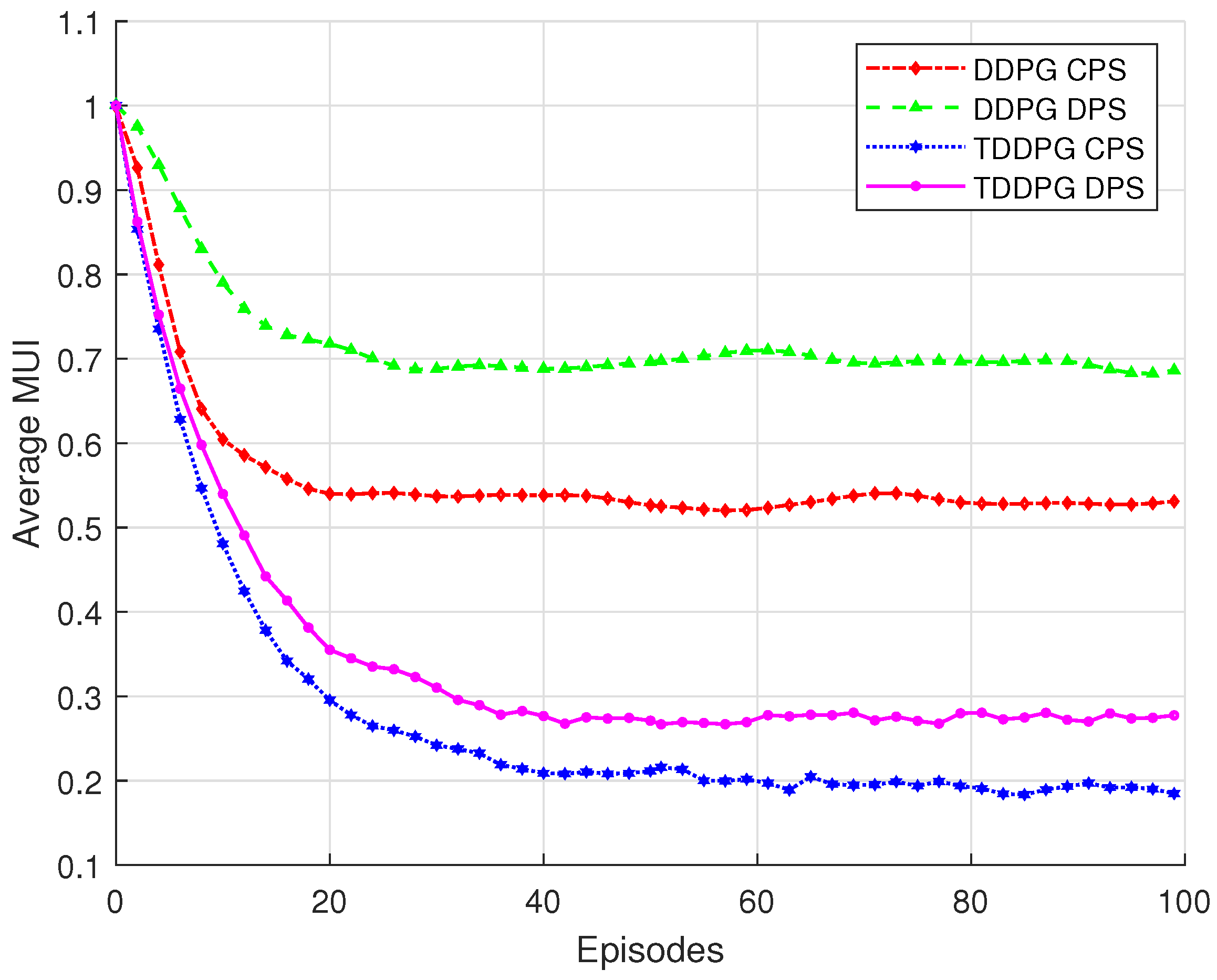
Figure 3 compares the performance of the TDDPG algorithm and the original DDPG algorithm under different RIS phase shift optimization strategies in terms of average MUI. As shown in the figure, although both DDPG and TDDPG algorithms eventually converge, the TDDPG algorithm achieves faster convergence and better final performance, demonstrating stronger stability and adaptability to dynamic environments. Moreover, the continuous phase shift strategy (CPS) consistently outperforms the discrete phase shift strategy (DPS) under both algorithms. Unlike discrete phase shifts, which are limited to a set of fixed values, the continuous strategy enables fine-grained control of the RIS phase shifts across a wider range, allowing more precise manipulation of electromagnetic wave propagation and reflection. This significantly reduces the average interference in the system. Among all configurations, the TDDPG, combined with CPS, achieves the lowest average MUI, indicating the best overall performance.
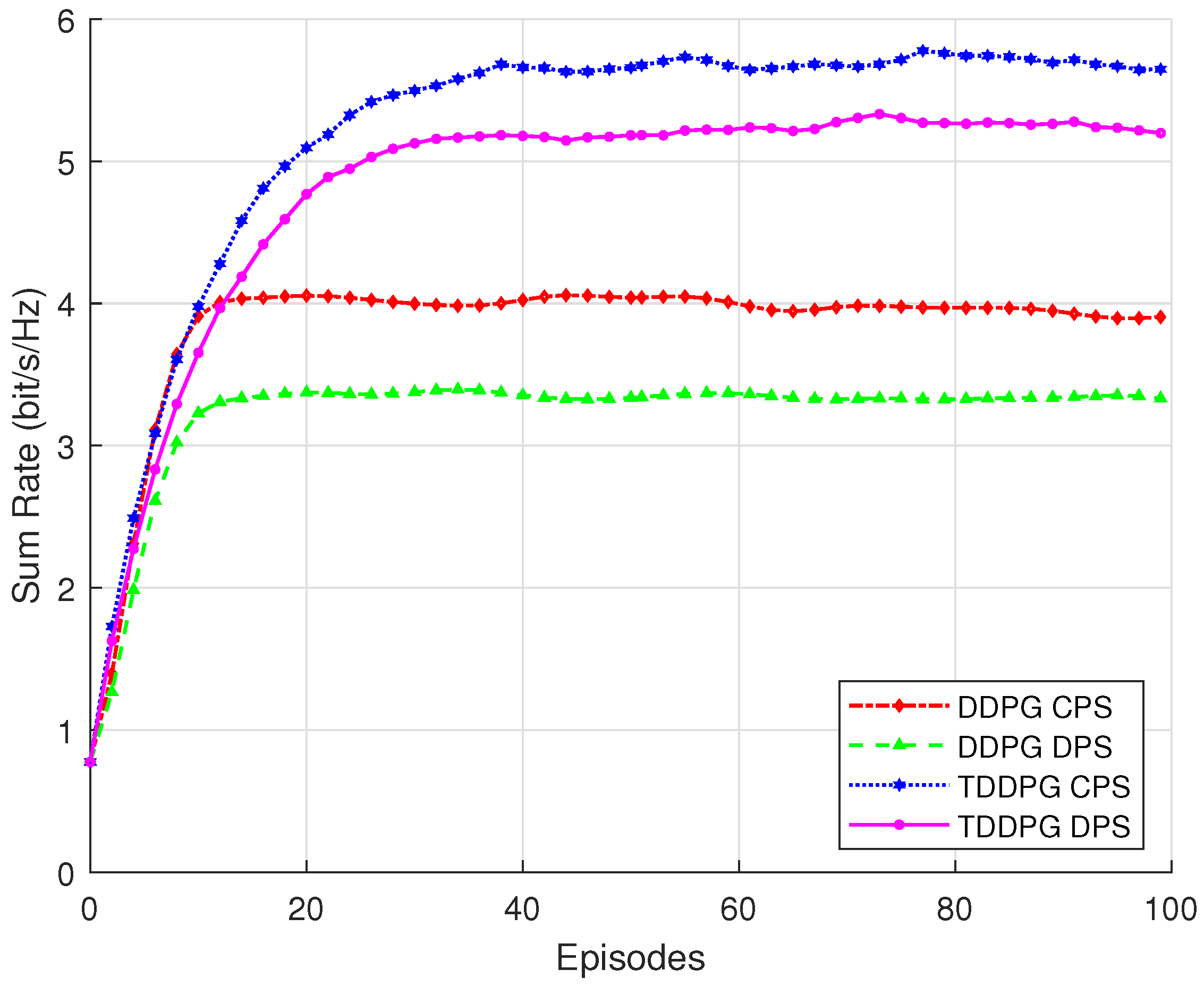
Figure 4 presents the optimization performance of the TDDPG and original DDPG algorithms under CPS and DPS strategies in terms of communication sum rate. It is evident that the TDDPG algorithm outperforms the traditional DDPG under both CPS and DPS configurations, achieving faster convergence and a higher final sum rate. This demonstrates that the proposed TDDPG architecture more effectively coordinates the joint optimization of transmit beamforming and RIS phase shifts, fully exploiting the system’s performance potential.
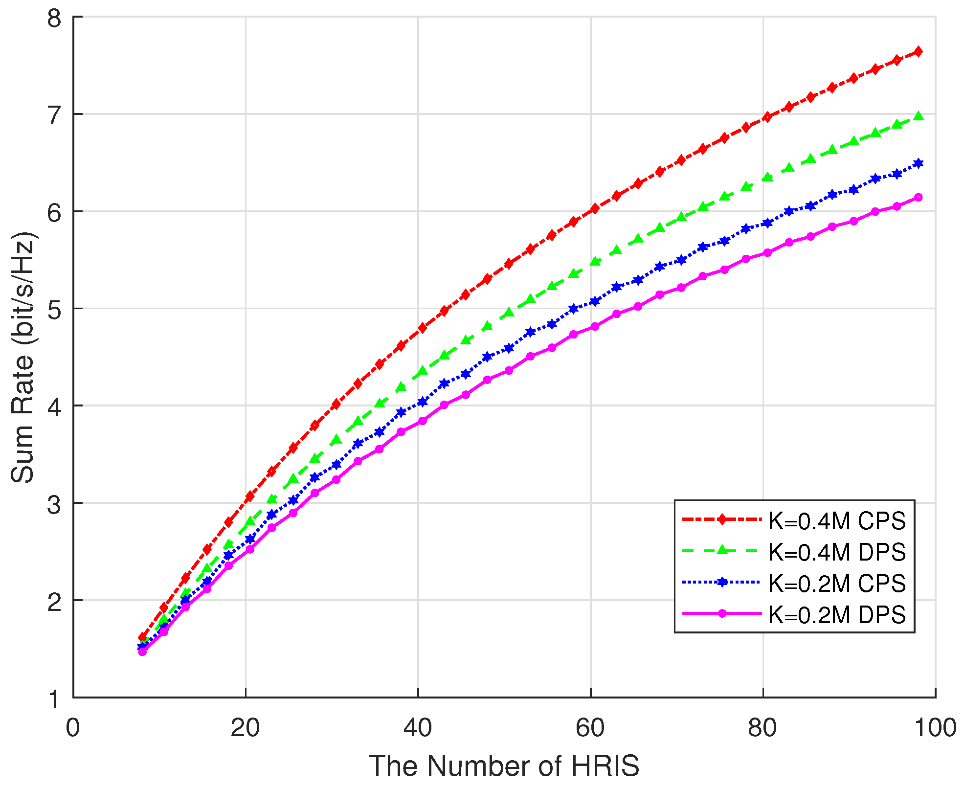
Figure 5 shows the performance of hybrid RIS systems with different numbers of active elements under different RIS phase shift optimization strategies. It can be observed that as the number of active elements in the hybrid RIS increases, the system’s sum rate exhibits a steady upward trend. This is because a greater number of active elements provides higher degrees of freedom for fine-grained control over the phase and amplitude of signals, thereby enhancing beamforming capability and improving the quality and efficiency of communication links. However, the increase in active components also leads to higher manufacturing and maintenance costs. Moreover, as the number of active elements grows, the system’s total power consumption and heat dissipation requirements also rise, which may result in decreased energy efficiency. Therefore, in practical deployments, it is necessary to determine an appropriate number of active elements based on the specific application requirements and system constraints.
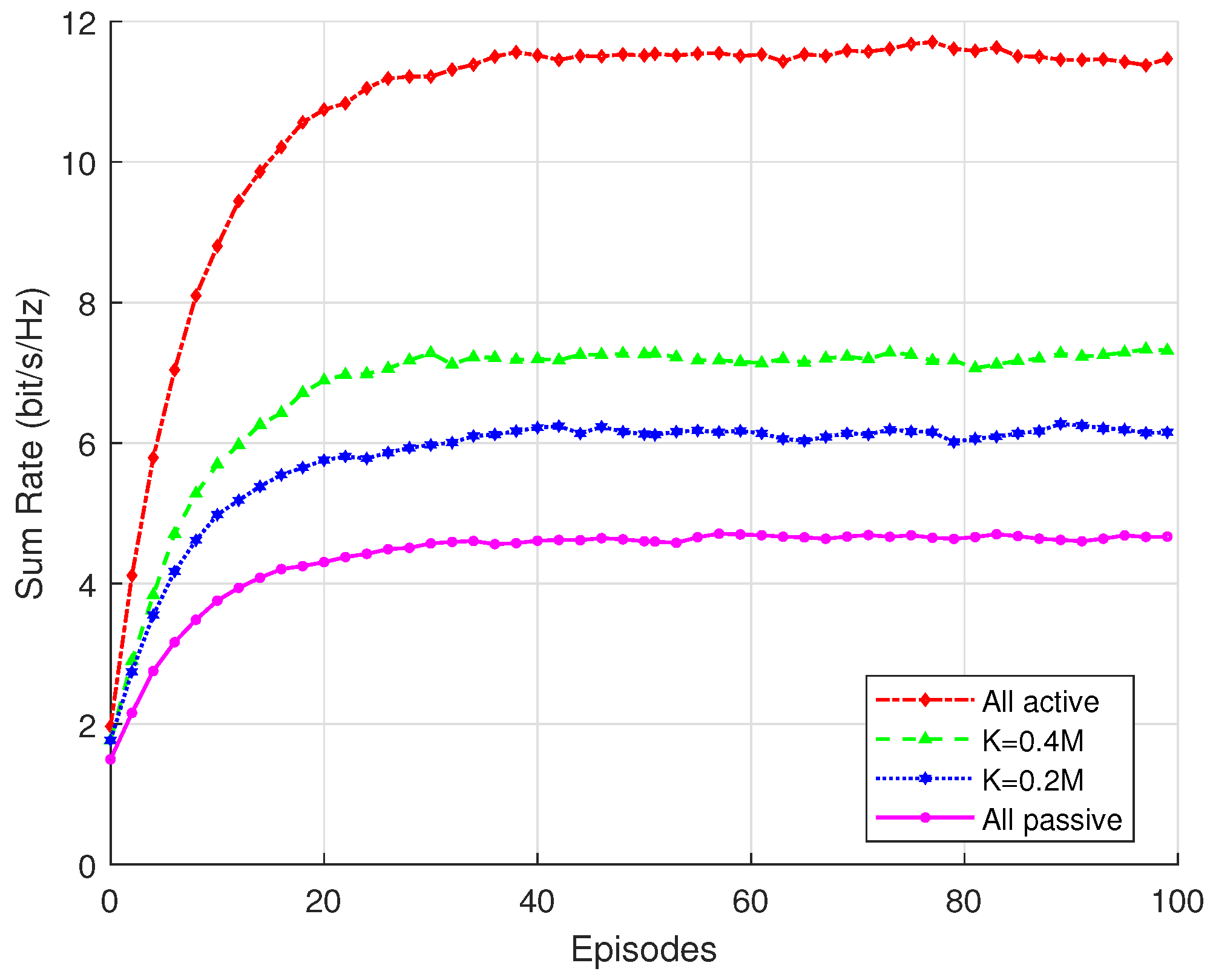
Figure 6 illustrates the impact of all active RISs and hybrid RISs with different proportions of active elements and all passive RISs on communication performance and sum rate. It can be observed that the fully active RIS achieves the best performance, reaching the highest sum rate, while the fully passive RIS exhibits the lowest performance. The hybrid RIS lies between the two, with its communication performance improving as the number of active elements increases. This indicates that a hybrid RIS offers a favorable trade-off between performance and cost. By appropriately configuring a portion of active elements, the system can significantly enhance its communication performance without substantially increasing complexity and power consumption. At the same time, it achieves considerable reductions in energy consumption and deployment cost, making it more practical for real-world applications. Moreover, the hybrid RIS architecture provides high flexibility, allowing the ratio of active to passive elements to be dynamically adjusted according to specific application scenarios and environmental conditions, thereby adapting to diverse communication requirements.
5. Conclusions
In this paper, a hybrid RIS-assisted communication method is considered for ISAC in IoV scenarios. Due to the additional noise introduced by the active components within the RIS, the SNR of both radar sensing and wireless communication may be adversely affected. This not only interferes with the normal communication process but also significantly degrades signal quality, thereby reducing overall system performance. To address this challenge, a joint optimization problem is formulated for the RIS phase shift matrix and transmit beamforming under constraints such as total transmit power, RIS-induced noise power, and the CRLB of angle estimation. A joint optimization algorithm based on a TDDPG architecture is proposed to tackle the tightly coupled optimization variables. The algorithm combines deep reinforcement learning with optimization theory and iteratively updates the RIS phase shifts and beamforming parameters to gradually approach the optimal solution. The simulation results demonstrate that the proposed TDDPG-based method effectively addresses the complex optimization problem. Compared with the conventional DDPG algorithm, the proposed approach exhibits faster convergence, improved stability, and better adaptability to dynamic environments.
However, this algorithm still has some limitations, especially in complex scenarios. For instance, if we originally trained the system on 20 users, but the peak number of users in the scenario reached 100, then the system performance would inevitably decline. Secondly, in our ISAC design, the state space includes the continuous positions of the vehicles and the various elements of the cascaded channel matrix H, while the action space is composed of the RIS phase shift vector and the beamforming vector for transmission. When the number of active RISs increases, the calculation time will grow exponentially. We will attempt to use new methods such as distributed computing or online learning in future work to solve these problems.
This study proposes an adaptive resource allocation framework for hybrid RISs, aiming to ensure communication reliability and efficiency in ISAC scenarios for the IoV. The findings provide a theoretical basis for RIS deployment in future 6G IoV networks. Future work will focus on extending the proposed optimization framework by integrating machine learning-based interference prediction and adaptive beamforming techniques to further enhance system performance in more complex and dynamic environments. Additionally, real-time hardware implementation and network scalability will be explored to validate the feasibility and practicality of the proposed solution in large-scale, high-density networks.


