Article

RRT-GPMP2: A Motion Planner for Mobile Robots in Complex Maze Environments

1
Department of Computer Science, University College London, London WC1E 6BT, UK
2
Department of Mechanical Engineering, University College London, London WC1E 6BT, UK
3
Hawkes Institute, University College London, London WC1E 6BT, UK
*
Authors to whom correspondence should be addressed.
Electronics 2025, 14(14), 2888; https://doi.org/10.3390/electronics14142888
Submission received: 9 June 2025 / Revised: 2 July 2025 / Accepted: 7 July 2025 / Published: 18 July 2025

Abstract

With the development of science and technology, mobile robots are playing a significant role in the new round of world revolution. Mobile robots could serve as assistants or substitutes for humans across a wide range of applications. To enhance mobile robot automation, advanced motion planners must be integrated to handle diverse environments. Navigating complex maze environments is a key challenge for mobile robots in various practical scenarios. Therefore, this article proposes a novel hierarchical motion planner named the rapidly exploring random tree-based Gaussian process motion planner 2, which aims to tackle the motion planning problem for mobile robots in complex maze environments. Specifically, the proposed motion planner successfully combines the advantages of the trajectory optimisation motion planning method and sampling-based motion planning method. To validate the performance and practicability of the proposed motion planner, we tested it in a series of self-constructed maze simulations and applied it on a surface marine robot in a high-fidelity maritime simulation environment in the Robot operating system.

1. Introduction

Over the past years, mobile robots have found extensive applications in diverse domains and are still evolving at a rapid pace. Depending on the scope of applications, mobile robots can be classified as aerial robots, ground robots, marine robots, and others. Real-world implementations of ground robots are ubiquitous nowadays, ranging from autonomous urban mobility to commercial logistics automation. Compared with ground robots, aerial robots such as different multicopter drones can enter hard-to-access places such as caves and post-disaster ruins. Furthermore, aerial robots can provide a better perspective in surveillance, search, and observation missions. Marine robots, such as surface marine robots and underwater marine robots, can be used to perform various maritime missions including autonomous transportation missions and deep-sea exploration missions. Navigating complex maze environments is a unique challenge for mobile robots in performing autonomous missions. For example, unmanned aerial vehicles and unmanned underwater vehicles must navigate complex, maze-like environments when performing autonomous search and rescue operations in post-disaster scenarios. Self-driving cars and unmanned surface vehicles face significant navigation challenges when executing parking maneuvers in complex, maze-like infrastructure such as multi-level garages and congested port facilities.
Central to the functionality of mobile robots is the capability to autonomously find a path or trajectory in the applicable environment [1,2,3]. Such a capability is normally achieved by developing and designing motion planning algorithms. Motion planning is an essential component to ensure mobile robots can successfully perform autonomous missions in maze-like environments. High-performance motion planning algorithms can enhance the reliability of mobile robots in complex maze environments. Current existing mainstream motion planning algorithms can be divided into three categories: (1) path planning methods such as grid-based motion planners and sampling-based motion planners [4,5,6,7,8], (2) trajectory planning methods such as trajectory optimisation motion planners [9,10,11,12,13,14], and (3) obstacle avoidance strategies such as dynamic window approach [15,16,17,18]. In path planning, a geometric path is generated with a sequence of waypoints from a start point to a goal point. In trajectory planning, geometric paths are generated and associated with time information. The obstacle avoidance strategy enables direct real-time robot control, eliminating the requirement for explicit path or trajectory generation. Among the mainstream motion planning algorithms, the performance of trajectory optimisation motion planners is superior, which is reflected in the following features: (1) extremely fast computational speed and (2) high-quality trajectory generation [13,19]. Nevertheless, the performance of trajectory optimisation motion planners is constrained in complex maze environments. Although there is some research about applying trajectory optimisation motion planners in simple maze environments [20,21], the proposed methods in these studies [20,21] heavily rely on pre-defined Gaussian Process (GP) priors. Constraints on the complexity of these GP priors limit their applicability to relatively simple maze environments. Thus, there is still a lack of enhancing the performance of trajectory optimisation motion planners in complex maze environments through integrating them with other functionally complementary motion planners, rather than solely relying on GP prior optimisation.
To address this challenge, this article proposes a hierarchical motion planner, referred to as rapidly exploring random tree-based Gaussian process motion planner 2 (RRT-GPMP2). The proposed RRT-GPMP2 algorithm employs a trajectory optimisation motion planner (Gaussian process motion planner 2 or GPMP2) as the primary method for motion planning in complex maze environments. When GPMP2 encounters performance constrains in specific regions, it dynamically supplements itself with a sampling-based method (rapidly exploring random tree or RRT) to ensure effective motion planning. In short, the proposed RRT-GPMP2 algorithm merges the strengths of trajectory optimisation and sampling-based planning. In hybrid approaches for motion planning in complex maze environments, sampling-based methods are typically employed as the local re-planning strategy due to their inherent randomness and efficient exploration capabilities. The main difference between hybrid approaches lies primarily in the choice of global planning strategy. As demonstrated in previous research [12,13], GPMP2 offers several advantages over other mainstream motion planning algorithms, which makes it particularly suitable for the global planning. Reinforcement learning approaches can interact with the complex maze environments during the training process and might eventually obtain a better performance compared with hybrid approaches. However, the training process of reinforcement learning approaches typically requires substantial computational time [22].
In this study, the proposed RRT-GPMP2 algorithm is validated in two self-constructed complex mazes in simulations. To further validate its practicability, an additional test is conducted using a surface marine robot in a high-fidelity maritime simulation environment based on the Robot operating system (ROS). A demonstration of the selected surface marine robot in ROS is provided in Figure 1.
The scientific novelty and contributions of this article are summarised as follows:
  • The RRT-GPMP2 algorithm is proposed to solve the motion planning problem in complex maze environments. Specifically, it effectively combines GPMP2 global planning and RRT local re-planning.
  • The proposed RRT-GPMP2 algorithm is thoroughly tested in a series of simulations to validate its performance and practicability.
The rest of this article is organised as follows: Section 2 presents the proposed RRT-GPMP2 algorithm and the used fully autonomous unmanned surface vehicle navigation framework in detail. Section 3 demonstrates the simulation results of the proposed RRT-GPMP2 algorithm in two self-constructed complex mazes and a high-fidelity maritime simulation environment in ROS. Section 4 discusses the performance of the proposed RRT-GPMP2 algorithm in two self-constructed complex mazes. Section 5 concludes this article, while Section 6 proposes a series of future research directions.

2. Materials and Methods

In this section, we describe the proposed RRT-GPMP2 algorithm and the used fully autonomous unmanned surface vehicle navigation framework in detail.

2.1. RRT-GPMP2

This subsection presents the proposed RRT-GPMP2 algorithm, in detail, which can be divided into two main parts: (1) GPMP2 global planning and (2) RRT local re-planning. Specifically, we present (1) the principle of GPMP2 algorithm in Section 2.1.1, (2) the principle of RRT algorithm in Section 2.1.2, and (3) the hierarchical planning architecture in Section 2.1.3.

2.1.1. GPMP2

This part details GPMP2 algorithm, which is used as the global planning part of the proposed RRT-GPMP2 algorithm. GPMP2 algorithm was proposed in studies [11,12] and used in our previous studies [13,19]. These studies are briefly summarised to explain the principle of GPMP2 algorithm.
GP-based motion planning algorithms, such as GPMP2, view motion planning as a probabilistic inference process, which infers an optimised posterior based on the GP prior and likelihood distributions [11,12,13,19]. The probabilistic inference process to obtain an optimised posterior is named the maximum a posteriori estimation and can be formulated as: θ * = arg   max θ p ( θ ) l ( θ ; e ) , where θ * is the optimised posterior, p ( θ ) is the GP prior distribution, and l ( θ ; e ) is the likelihood distribution. p ( θ | e ) can also be used to describe the optimised posterior. The Levenberg–Marquardt method is used to solve the least squares problem during the optimisation process of GPMP2. The GP prior is a vector-valued GP that contains several continues-time trajectories samples: θ ( t ) GP ( μ ( t ) , K ( t , t ) ) , where μ ( t ) is a vector-valued mean function and K ( t , t ) is a matrix-valued covariance function. The GP prior distribution can be expressed as: p ( θ ) e x p { 1 2 | | θ u | | K 2 } . In GPMP2, a constant-velocity system dynamics model is used to generate the GP prior. The likelihood describes the probability of having a collision with any obstacle at each point in the environment and it can be expressed as: l ( θ ; e ) = e x p { 1 2 | | h ( θ ) | | Σ o b s 2 } , where Σ obs is a hyper-parameter matrix and h ( θ ) is a vector-valued obstacle cost function: h ( θ i ) = [ c ( d ( θ i ) ) ] , where c is a hinge loss function and d is the signed distance of a point. Furthermore, factor graph is used as an optimisation tool to deal with the probabilistic inference in maximum a posteriori estimation in GPMP2 algorithm. The difference between GPMP, the original version of GP-based motion planning, and GPMP2, an improved version of GPMP, is that GPMP2 employs a factor graph to reduce the time cost during the optimisation process. The factor graph can be formulated as: G = { Θ , F , E } , where Θ = { θ 0 , . . . , θ N } are variable nodes, F = { f 0 , . . . , f M } are factor nodes, and E are edges that connect the variable nodes and factor nodes. The posterior factorisation can be expressed as: p ( θ | e ) m = 1 M f m ( Θ m ) , where f m are a series of factors on variable subset Θ m [11,12].

2.1.2. RRT

This part details the RRT algorithm, which is used as the local planning part of the proposed RRT-GPMP2 algorithm. The RRT algorithm was proposed in [25] and explained in detail in [26,27,28,29]. These studies are briefly summarised to explain the principle of RRT.
The RRT algorithm generates a tree structure from a start point to a goal point in a space while avoiding any obstacles [25,26,27]. The generated tree structure can be viewed as a collision-free path T = ( V , E ) , where V represents the vertices on the tree structure and E represents the edges on the tree structure. The entire metric space is represented as X, the region with static obstacles is represented as X o b s X , and the region without static obstacles is represented as X f r e e X . The start point of the motion planning problem is represented as x s t a r t X f r e e and the goal point is represented as x g o a l X f r e e . The general process of the RRT algorithm to construct a tree structure is demonstrated in Algorithm 1 and it can be summarised as follows:
  • Sample( X f r e e , N ) generates a random point x r a n d inside the region without static obstacles X f r e e if the tree structure T = ( V , E ) has not reached the goal point x g o a l .
  • Nearest( V , x r a n d ) performs a comparison between the randomly sampled point x r a n d and the rest states in the set of nodes V to find the nearest point x n e a r e s t to x r a n d .
  • Steer( x n e a r e s t , x r a n d ) generates a new point x n e w , which is closer to x n e a r e s t by connecting x r a n d and x n e a r e s t with a steering function.
  • CollisionFree( x n e a r e s t , x n e w ) checks if there is any collision between the straight path from x n e w to x n e a r e s t and the region with static obstacles X o b s .
  • The new point x n e w is added to the set of nodes V and the new edges that connect x r a n d and x n e w are added to the set of edges E.
  • The mentioned processes repeat for N times until the tree structure T = ( V , E ) reaches the goal point x g o a l .
Algorithm 1: RRT algorithm [28,29]
Electronics 14 02888 i001

2.1.3. Hierarchical Planning Architecture

This part details the process of the proposed RRT-GPMP2 algorithm, which successfully combines the GPMP2 global planning and the RRT local re-planning in an effective manner.
The GPMP2 algorithm can generate a path significantly faster than conventional methods due to the guidance of the mean and covariance of the GP prior samples and the efficiency of the incremental optimisation tool [11,12]. Nevertheless, the path generated by the GPMP2 algorithm cannot satisfy the collision-free requirement in most complex maze environments. Compared with the GPMP2 algorithm, the RRT algorithm can always generate a feasible path in complex maze environments. But the RRT algorithm usually requires a relatively long computational time and the smoothness of the generated path cannot be guaranteed.
Thus, we propose the RRT-GPMP2 algorithm, which uses the GPMP2 algorithm described in Section 2.1.1 to generate a global path and allows collisions to occur on it and then uses the RRT algorithm described in Section 2.1.2 to generate a local collision-free path to substitute the collision part of the global path.
To give a more intuitive understanding of the proposed RRT-GPMP2 algorithm, the flow diagram of its hierarchical planning architecture is provided in Figure 2. The detailed process of the proposed RRT-GPMP2 algorithm is summarised as follows:
  • GPMP2 global planning generates a global path that possibly collides with the maze based on the global start point and global goal point.
  • Waypoint finder traverses the global path to find the last waypoint before collision as the start point of local re-planning and the first waypoint after collision as the goal point of local re-planning. While executing the traversal algorithm, waypoints with collisions are represented by a value of ’1’, while those without collisions are represented by ’0’, as the maze environment is modelled using a binary map.
  • RRT local re-planning generates a collision-free local path based on the local start point and local goal point.
  • Waypoint trimmer then removes the collision part of the global path and maintains the collision-free parts on the global path.
  • Waypoint integrator merges the collision-free parts on the global path with the local collision-free path.

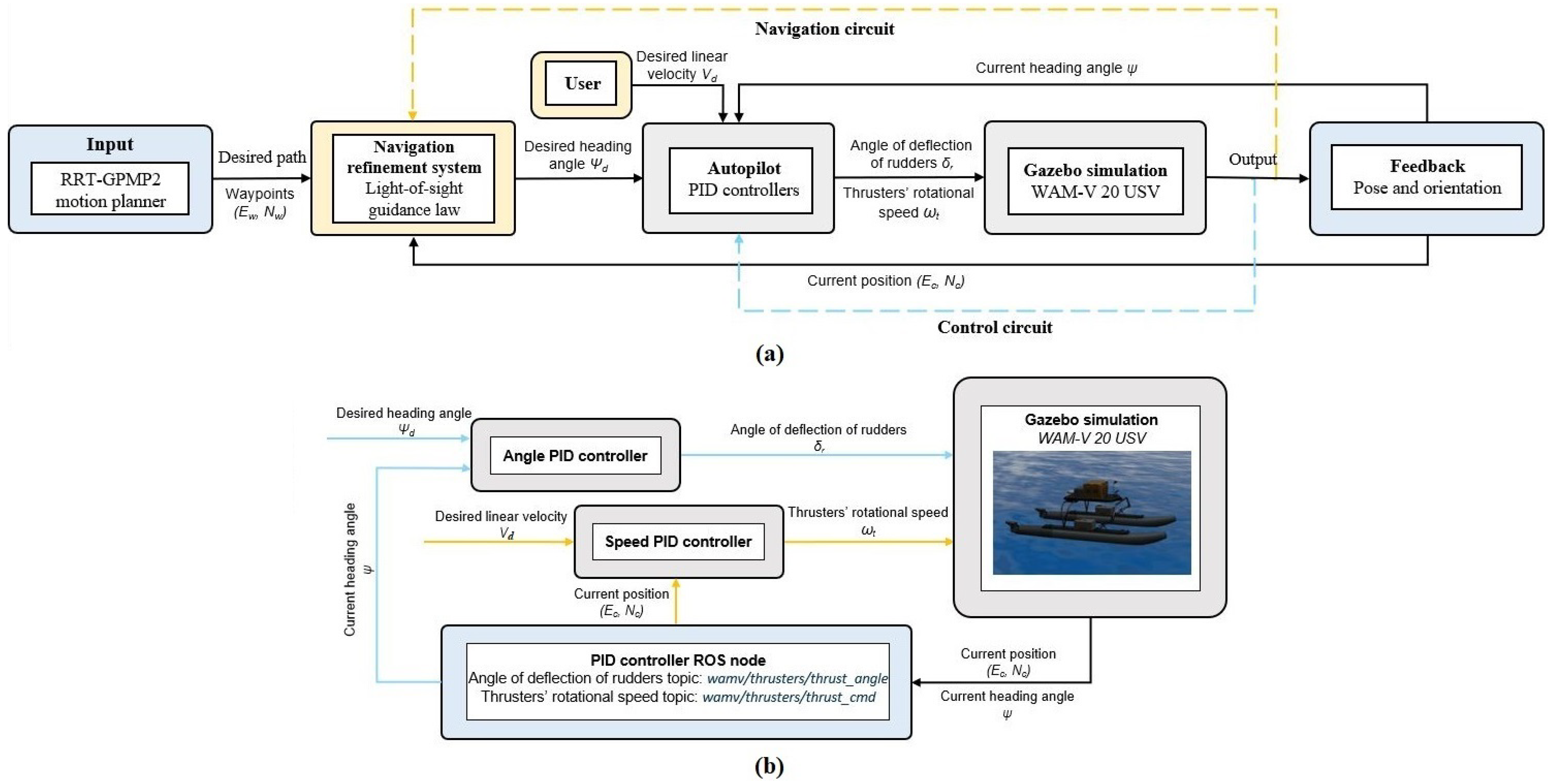
2.2. Fully Autonomous Unmanned Surface Vehicle Navigation Framework

This subsection presents the used fully autonomous unmanned surface vehicle (USV) navigation framework in detail.
The next section tests the proposed RRT-GPMP2 algorithm in a fully autonomous USV navigation framework in a high-fidelity ROS maritime environment to showcase its practicability [19]. This framework was proposed in a previous study in [19] and it was designed based on an open-source repository provided in [23]. The overall structure of the entire system including the proposed RRT-GPMP2 algorithm and the framework is demonstrated in Figure 3a, while the detailed structure of the two controllers in the framework is demonstrated in Figure 3b.
Figure 2. Flow diagram of the hierarchical planning architecture in the proposed RRT-GPMP2 algorithm.
Electronics 14 02888 g002
Figure 3. (a) Overall structure of the entire system that includes the proposed RRT-GPMP2 algorithm and the fully autonomous USV navigation framework proposed in [19]. (b) Detailed structure of the two controllers in the autopilot in sub-figure (a) [19,23].
Electronics 14 02888 g003

3. Results

This section presents the simulation results in a series of self-constructed complex mazes and a high-fidelity maritime simulation environment in ROS.

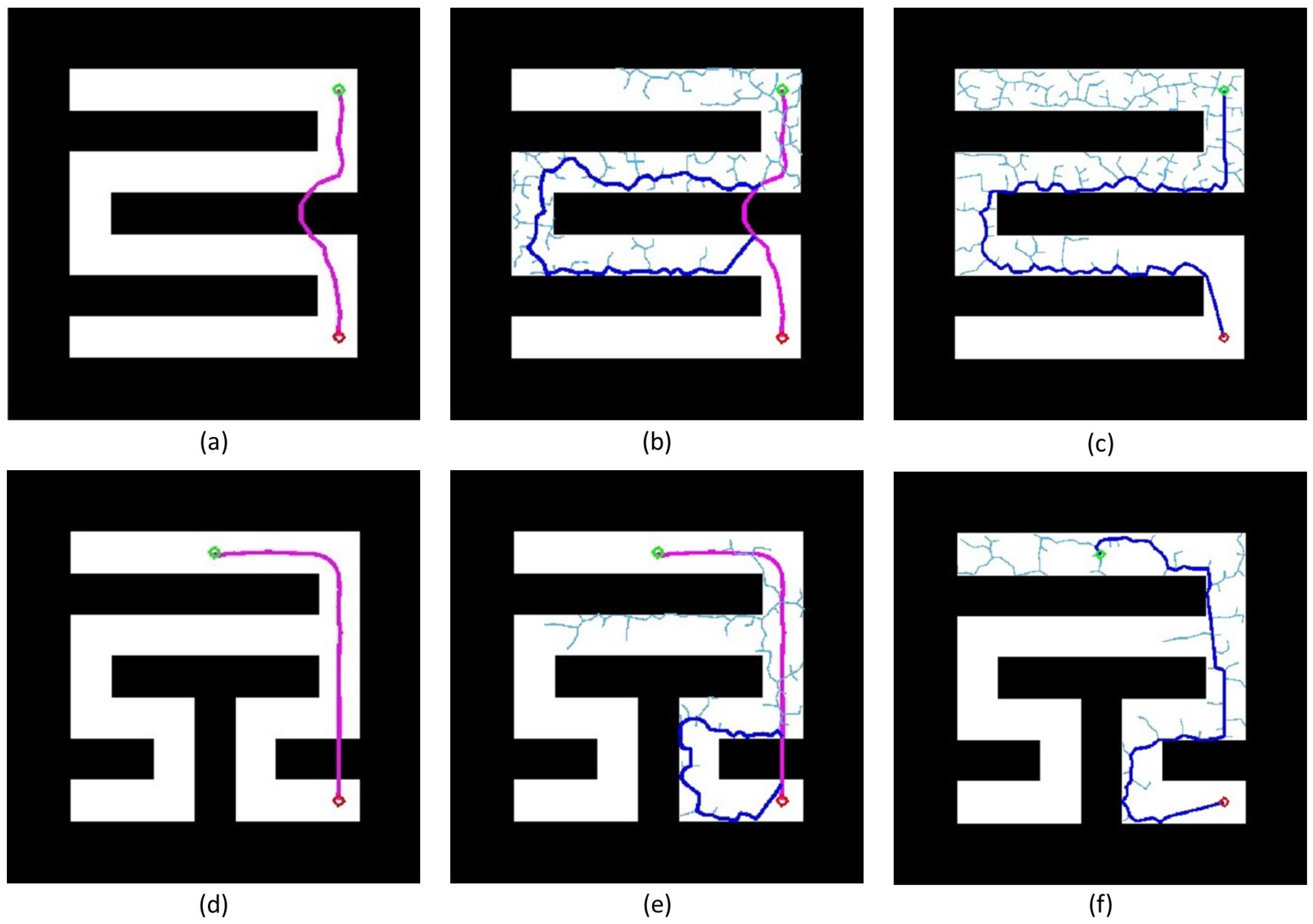
3.1. Results in Self-Constructed Complex Mazes

We use the proposed RRT-GPMP2 algorithm and RRT global planning to generate paths and record results for each motion planning problem in two self-constructed complex mazes. The proposed RRT-GPMP2 algorithm is designed on the basis of the GPMP2 open-source repository in [11,12,30,31] and the RRT open-source repository in [31]. The GPMP2 global planning parameters are empirically selected based on extensive prior experimentation. For both the motion planning problems in the different maze environments, the step length of RRT (global planning and local re-planning) is defined as 10 [m] because this is a suitable value in 500 × 500 resolution maps based on tests. Simulations are run on a computer with 16 2.3-GHz Intel Core i7-11800H processors and a 8 GB RAM.
In the first motion planning problem, the start and goal positions are [400, 400] and [400, 100], respectively. Furthermore, the start and goal positions when the proposed RRT-GPMP2 algorithm starts to re-planning the path are [374, 286] and [367, 222], respectively. The detailed GPMP2 global planning process of the proposed RRT-GPMP2 algorithm in the first motion planning problem is demonstrated in Figure 4a, while the detailed RRT local re-planning process of the proposed RRT-GPMP2 algorithm in the first motion planning problem is demonstrated in Figure 4b. Moreover, the detailed RRT global planning process in the first motion planning problem is demonstrated in Figure 4c. Table 1 summarises the GPMP2 global planning and RRT local re-planning of the proposed RRT-GPMP2 algorithm in the first motion planning problem, while Table 2 compares the simulation results of the RRT-GPMP2 algorithm and RRT global planning in the first motion planning problem. In the second motion planning problem, the start position is [250, 400] and the goal position is [400, 100]. The start and goal positions when the proposed RRT-GPMP2 algorithm starts to use the RRT algorithm to re-planning the path are [401, 176] and [400, 120], respectively. The detailed GPMP2 global planning process of the proposed RRT-GPMP2 algorithm in the second motion planning problem is demonstrated in Figure 4d, while the detailed RRT local re-planning process of the proposed RRT-GPMP2 algorithm in the second motion planning problem is demonstrated in Figure 4e. Additionally, the detailed RRT global planning process in the second motion planning problem is demonstrated in Figure 4f. Table 3 summarises the GPMP2 global planning and RRT local re-planning of the proposed RRT-GPMP2 algorithm in the second motion planning problem, while Table 4 provides a summary of the simulation results of the RRT-GPMP2 algorithm and RRT global planning in the second motion planning problem. Figure 5 compares the total time cost between the proposed RRT-GPMP2 algorithm and RRT global planning in both motion planning problems, while Figure 6 compares the path length between the proposed RRT-GPMP2 algorithm and RRT global planning in both motion planning problems.
To evaluate the performance of the proposed RRT-GPMP2 algorithm in larger and more complex maze environments, we also employed it in a 1000 × 1000 resolutions map as demonstrated in Figure 7. The hardware platform and step length for RRT local re-planning remain unchanged from the previous simulations in two self-constructed complex mazes. In GPMP2 global planning, the start position is [600, 150] and the goal position is [440, 840]. In RRT local re-planning, the start position is [573, 328] and the goal position is [552, 403]. Based on the results in Figure 7, the robustness and scalability of the proposed RRT-GPMP2 algorithm are validated. Nevertheless, if the complexity and scale of the maze continues to increase, the proposed RRT-GPMP2 algorithm might not be able to generate a feasible path as there might be multiple complex collision parts on the generated path. As a result, additional strategies based on the proposed RRT-GPMP2 algorithm should be proposed to further solve this problem.

3.2. Result in a High-Fidelity Maritime Simulation Environment in ROS

There are several maze-like scenarios in the inshore maritime environment such as the complex, maze-like ports. In this path-following mission in ROS, a virtual maze is assumed to exist on the ocean surface in the ROS simulation environment. In this virtual maze, the selected wave adaptive modular vessel (WAM-V 20 USV) follows a path generated by the proposed RRT-GPMP2 algorithm based on the fully autonomous USV navigation framework. Figure 8a demonstrates the locations of the virtual maze, start point and goal point, while Figure 8b provides an overview of the ROS simulation environment of the path-following mission. As demonstrated in Figure 8a, the positions of the start point and goal point are [400, 100] and [400, 400], respectively. As demonstrated in Figure 8b, a WAM-V 20 USV is initialised at a point on the ocean surface and the maze configuration is implicit in ROS. The maze obstacle configuration is modelled in MATLAB, where the path is generated and subsequently transferred to Gazebo (https://gazebosim.org/home) via a ROS node.
To provide a more intuitive understanding of the path-following mission, the storyboards of the mission from a third-person perspective are shown in Figure 9. A comparison of the desired path and real path in the mission is provided in Figure 10. As demonstrated in Figure 10, although there were some drifts during the path-following process, the USV successfully followed the path generated by the proposed RRT-GPMP2 algorithm.

4. Discussions

In this section, the performance of the proposed RRT-GPMP2 algorithm in two self-constructed complex mazes is discussed.

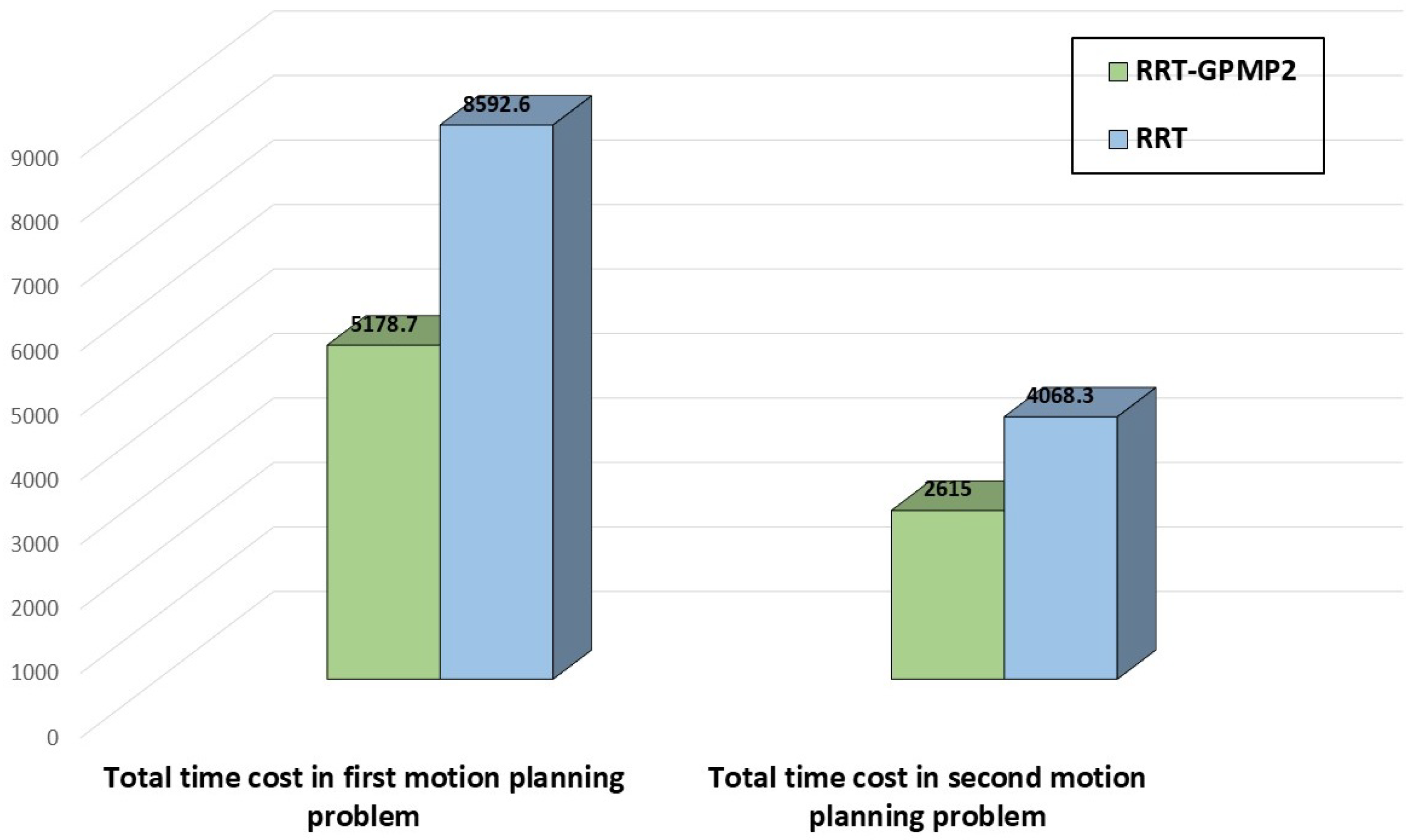
4.1. First Motion Planning Problem in Self-Constructed Complex Maze

As demonstrated in Table 1, the GPMP2 global planning process of the proposed RRT-GPMP2 algorithm can generate a global path in an extremely short time. Specifically, this process costs 27.1 [ms] and is only 0.52 [%] of the total time cost. On the other hand, the total time cost of the RRT local re-planning process of the proposed RRT-GPMP2 algorithm is 5151.6 [ms] and makes up the majority of the total time cost. This is because the RRT explores the maze environment without bias on the searching direction. It is beneficial for the RRT to find a feasible path. However, this diffuse search is time-consuming. The total time cost of the RRT global planning is 8592.6 [ms], as demonstrated in Table 2, and it is significantly higher than the total time cost of the proposed RRT-GPMP2 algorithm. Moreover, the path lengths of the proposed RRT-GPMP2 algorithm and RRT global planning are similar according to Table 2. Based on Figure 5 and Figure 6, we know that the proposed RRT-GPMP2 algorithm largely decreases the total time cost and maintains a similar path length of the generated path compared with the RRT global planning. The total time cost of the proposed RRT-GPMP2 algorithm is 60.27 [%] of the total time cost of the RRT global planning. The path length of the proposed RRT-GPMP2 algorithm is 104.98 [%] of the path length of the RRT global planning.

4.2. Second Motion Planning Problem in Self-Constructed Complex Maze

The GPMP2 global planning process of the proposed RRT-GPMP2 algorithm in this motion planning problem is 40.2 [ms], as demonstrated in Table 3, and is 1.54 [%] of the total time cost of the proposed RRT-GPMP2 algorithm. It is similar to the situation in the first motion planning problem, whereby the total time cost of the RRT local re-planning process still makes up the majority of the total time cost of the proposed RRT-GPMP2 algorithm. The total time cost of the RRT global planning is 4068.3 [ms], as demonstrated in Table 4, and it is still much larger than the total time cost of the proposed RRT-GPMP2 algorithm. Similar again to the situation in the first motion planning problem, the proposed RRT-GPMP2 and RRT have similar path lengths based on Table 4. Based on Figure 5 and Figure 6, we can see that the proposed RRT-GPMP2 algorithm significantly reduces the total time cost and maintains a similar path length compared with the RRT global planning. More specifically, the total time cost of the proposed RRT-GPMP2 algorithm is 64.28 [%] of the total time cost of the RRT global planning. The path length of the proposed RRT-GPMP2 algorithm is 109.91 [%] of the path length of the RRT global planning. As shown in Figure 4, majority of the path generated by the proposed RRT-GPMP2 algorithm is smooth, but the path generated by the RRT global planning is zigzag from the start point to the goal point. In the proposed RRT-GPMP2 algorithm, only a portion of the path is zigzag. Because the GPMP2 global planning can always generate a smooth path, the proposed RRT-GPMP2 algorithm can guarantee that part of the generated path is smooth. However, the RRT global planning cannot guarantee smoothness on any part of the path due to its randomness.

4.3. Path-Following Mission in a High-Fidelity Maritime Simulation Environment in ROS

As demonstrated in Figure 10, the path generated by the proposed RRT-GPMP2 is feasible for the USV to navigate in the virtual maze on the ocean surface. Compared with the desired path, although some drift occurs in the real path, this is primarily caused by limitations of the autopilot and controllers. Furthermore, the part generated by GPMP2 global planning is relatively easy for the USV to follow, resulting in smaller tracking errors compared to the part generated by RRT local re-planning. This validates the effectiveness of employing GPMP2 as the global planning method while utilising RRT local re-planning as a supplementary method for maze navigation.

5. Conclusions

This article introduced an effective hierarchical motion planner, RRT-GPMP2, to tackle the motion planning problem for mobile robots in complex maze environments. To be more specific, the proposed RRT-GPMP2 algorithm successfully integrates the global planning of the GPMP2 algorithm and the local re-planning of the RRT algorithm. Additionally, the proposed RRT-GPMP2 algorithm was tested in two self-constructed complex maze environments and the simulation results can be summarised as follows: (1) the proposed RRT-GPMP2 algorithm can generate a feasible path with higher smoothness compared to the RRT global planning, (2) the path length of the proposed RRT-GPMP2 algorithm is similar to the path length of the RRT global planning, and (3) the total time cost of the RRT local re-planning and GPMP2 global planning in the proposed RRT-GPMP2 algorithm is lower compared to the time cost of the RRT global planning. The practicability of the proposed RRT-GPMP2 algorithm was also validated in a high-fidelity maritime simulation environment in ROS. The path generated by the proposed RRT-GPMP2 algorithm is capable of guiding a USV to move from a start point to a goal point in a 2D virtual maritime maze environment.
Overall, the proposed RRT-GPMP2 algorithm is an effective method to solve the motion planning problems in complex mazes. It demonstrates a relatively fast computational speed compared with RRT global planning. This is because the computational speed of GPMP2 is significantly faster than the computational speed of RRT and only a small part of the path generated by the proposed RRT-GPMP2 algorithm is constructed by RRT. However, the parameter tuning process for the proposed RRT-GPMP2 algorithm may require more time due to the hierarchical structure and a larger number of pre-defined parameters compared to traditional motion planning algorithms. The proposed algorithm’s performance in online applications still requires further verification as the current verifications are limited to offline applications.
For potential application scenarios in the real world, the proposed RRT-GPMP2 algorithm can be utilised in a wide range of complex maze-like environments, such as post-disaster ruins, nuclear power plant facilities, underground mines, large parking garages and retail warehouses, large distribution ports, submarine caves, etc.

6. Future Work

In terms of future research, a series of potential directions are proposed as follows:
  • The proposed RRT-GPMP2 algorithm involves multiple pre-defined parameters. Therefore, advanced learning methods can be employed to determine the optimal parameter configuration.
  • The current RRT-GPMP2 implementation is based on a 2D framework, which constrains its applicability in 3D scenarios. It is necessary to expand the potential application scenarios of the proposed RRT-GPMP2 algorithm by implementing it in a 3D framework.
  • The proposed RRT-GPMP2 algorithm should be tested on diverse robotic platforms, including aerial and ground robots, in real-world, real-time applications.

Author Contributions

Conceptualization, J.M.; Methodology, J.M.; Software, J.M.; Validation, J.M., Y.L., R.B. and D.S.; Formal analysis, J.M.; Investigation, J.M.; Resources, J.M.; Data curation, J.M.; Writing—original draft, J.M.; Writing—review & editing, J.M.; Visualization, J.M.; Supervision, D.S.; Project administration, J.M. and D.S.; Funding acquisition, D.S. All authors have read and agreed to the published version of the manuscript.

Funding

This work was supported in whole, or in part, by the Wellcome/EPSRC Centre for Interventional and Surgical Sciences (WEISS) [203145/Z/16/Z], the Department of Science, Innovation and Technology (DSIT) and the Royal Academy of Engineering under the Chair in Emerging Technologies programme. For the purpose of open access, the author has applied a CC BY public copyright licence to any author accepted manuscript version arising from this submission.

Data Availability Statement

The original contributions presented in this study are included in the article. Further inquiries can be directed to the corresponding author.

Conflicts of Interest

The authors declare no conflicts of interest.

References

  1. Kalakrishnan, M.; Chitta, S.; Theodorou, E.; Pastor, P.; Schaal, S. STOMP: Stochastic trajectory optimization for motion planning. In Proceedings of the 2011 IEEE International Conference on Robotics and Automation, Shanghai, China, 9–13 May 2011; IEEE: Piscataway, NJ, USA, 2011; pp. 4569–4574. [Google Scholar]
  2. Schulman, J.; Duan, Y.; Ho, J.; Lee, A.; Awwal, I.; Bradlow, H.; Pan, J.; Patil, S.; Goldberg, K.; Abbeel, P. Motion planning with sequential convex optimization and convex collision checking. Int. J. Robot. Res. 2014, 33, 1251–1270. [Google Scholar] [CrossRef]
  3. Zucker, M.; Ratliff, N.; Dragan, A.D.; Pivtoraiko, M.; Klingensmith, M.; Dellin, C.M.; Bagnell, J.A.; Srinivasa, S.S. Chomp: Covariant hamiltonian optimization for motion planning. Int. J. Robot. Res. 2013, 32, 1164–1193. [Google Scholar] [CrossRef]
  4. Dijkstra, E.W. A note on two problems in connexion with graphs. In Edsger Wybe Dijkstra: His Life, Work, and Legacy; Association for Computing Machinery: New York, NY, USA, 2022; pp. 287–290. [Google Scholar]
  5. Hart, P.E.; Nilsson, N.J.; Raphael, B. A formal basis for the heuristic determination of minimum cost paths. IEEE Trans. Syst. Sci. Cybern. 1968, 4, 100–107. [Google Scholar] [CrossRef]
  6. Kavraki, L.E.; Svestka, P.; Latombe, J.C.; Overmars, M.H. Probabilistic roadmaps for path planning in high-dimensional configuration spaces. IEEE Trans. Robot. Autom. 1996, 12, 566–580. [Google Scholar] [CrossRef]
  7. Meng, J.; Pawar, V.M.; Kay, S.; Li, A. UAV path planning system based on 3D informed RRT* for dynamic obstacle avoidance. In Proceedings of the 2018 IEEE International Conference on Robotics and Biomimetics (ROBIO), Kuala Lumpur, Malaysia, 12–15 December 2018; IEEE: Piscataway, NJ, USA, 2018; pp. 1653–1658. [Google Scholar]
  8. Gammell, J.D.; Srinivasa, S.S.; Barfoot, T.D. Informed RRT*: Optimal sampling-based path planning focused via direct sampling of an admissible ellipsoidal heuristic. In Proceedings of the 2014 IEEE/RSJ International Conference on Intelligent Robots and Systems, Chicago, IL, USA, 14–18 September 2014; IEEE: Piscataway, NJ, USA, 2014; pp. 2997–3004. [Google Scholar]
  9. Mukadam, M.; Yan, X.; Boots, B. Gaussian process motion planning. In Proceedings of the 2016 IEEE International Conference on Robotics and Automation (ICRA), Stockholm, Sweden, 16–21 May 2016; IEEE: Piscataway, NJ, USA, 2016; pp. 9–15. [Google Scholar]
  10. Yan, X.; Indelman, V.; Boots, B. Incremental sparse GP regression for continuous-time trajectory estimation and mapping. Robot. Auton. Syst. 2017, 87, 120–132. [Google Scholar] [CrossRef]
  11. Dong, J.; Mukadam, M.; Dellaert, F.; Boots, B. Motion planning as probabilistic inference using Gaussian processes and factor graphs. In Proceedings of the Robotics: Science and Systems, Ann Arbor, MI, USA, 18–22 June 2016; Volume 12. [Google Scholar]
  12. Mukadam, M.; Dong, J.; Yan, X.; Dellaert, F.; Boots, B. Continuous-time Gaussian process motion planning via probabilistic inference. Int. J. Robot. Res. 2018, 37, 1319–1340. [Google Scholar] [CrossRef]
  13. Meng, J.; Liu, Y.; Bucknall, R.; Guo, W.; Ji, Z. Anisotropic GPMP2: A fast continuous-time Gaussian processes based motion planner for unmanned surface vehicles in environments with ocean currents. IEEE Trans. Autom. Sci. Eng. 2022, 19, 3914–3931. [Google Scholar] [CrossRef]
  14. Meng, J.; Liu, Y.; Bucknall, R. A Fast Continuous-time Motion Planner for USVs in Oceanic Environments. In Proceedings of the 5th IEEE UK and Ireland Robotics and Autonomous Systems Conference, Edinburgh, UK, 23 February 2022. [Google Scholar]
  15. Dobrevski, M.; Skočaj, D. Dynamic adaptive dynamic window approach. IEEE Trans. Robot. 2024, 40, 3068–3081. [Google Scholar] [CrossRef]
  16. Chang, L.; Shan, L.; Jiang, C.; Dai, Y. Reinforcement based mobile robot path planning with improved dynamic window approach in unknown environment. Auton. Robot. 2021, 45, 51–76. [Google Scholar] [CrossRef]
  17. Yasuda, S.; Kumagai, T.; Yoshida, H. Safe and efficient dynamic window approach for differential mobile robots with stochastic dynamics using deterministic sampling. IEEE Robot. Autom. Lett. 2023, 8, 2614–2621. [Google Scholar] [CrossRef]
  18. Xu, W.; Zhang, Y.; Yu, L.; Zhang, T.; Cheng, Z. A local path planning algorithm based on improved dynamic window approach. J. Intell. Fuzzy Syst. 2023, 45, 4917–4933. [Google Scholar] [CrossRef]
  19. Meng, J.; Humne, A.; Bucknall, R.; Englot, B.; Liu, Y. A Fully-Autonomous Framework of Unmanned Surface Vehicles in Maritime Environments Using Gaussian Process Motion Planning. IEEE J. Ocean. Eng. 2022, 48, 59–79. [Google Scholar] [CrossRef]
  20. Petrović, L.; Peršić, J.; Seder, M.; Marković, I. Stochastic optimization for trajectory planning with heteroscedastic Gaussian processes. In Proceedings of the 2019 European Conference on Mobile Robots (ECMR), Prague, Czech Republic, 4–6 September 2019; IEEE: Piscataway, NJ, USA, 2019; pp. 1–6. [Google Scholar]
  21. Petrović, L.; Peršić, J.; Seder, M.; Marković, I. Cross-entropy based stochastic optimization of robot trajectories using heteroscedastic continuous-time Gaussian processes. Robot. Auton. Syst. 2020, 133, 103618. [Google Scholar] [CrossRef]
  22. Aradi, S. Survey of Deep Reinforcement Learning for Motion Planning of Autonomous Vehicles. IEEE Trans. Intell. Transp. Syst. 2022, 23, 740–759. [Google Scholar] [CrossRef]
  23. Bingham, B.; Agüero, C.; McCarrin, M.; Klamo, J.; Malia, J.; Allen, K.; Lum, T.; Rawson, M.; Waqar, R. Toward maritime robotic simulation in gazebo. In Proceedings of the OCEANS 2019 MTS/IEEE SEATTLE, Seattle, WA, USA, 27–31 October 2019; IEEE: Piscataway, NJ, USA, 2019; pp. 1–10. [Google Scholar]
  24. Ocean Power Technologies (WAM-V USV). 2024. Available online: https://oceanpowertechnologies.com/products/unmanned-surface-vehicles/ (accessed on 6 July 2025).
  25. LaValle, S. Rapidly-exploring random trees: A new tool for path planning. Comput. Sci. Dept. Oct. 1998, 98, 1–4. [Google Scholar]
  26. LaValle, S.M.; Kuffner, J.J., Jr. Randomized kinodynamic planning. Int. J. Robot. Res. 2001, 20, 378–400. [Google Scholar] [CrossRef]
  27. LaValle, S.M. Planning Algorithms; Cambridge University Press: Cambridge, UK, 2006. [Google Scholar]
  28. Karaman, S.; Frazzoli, E. Sampling-based algorithms for optimal motion planning. Int. J. Robot. Res. 2011, 30, 846–894. [Google Scholar] [CrossRef]
  29. Gao, Y.; Meng, J.; Shu, J.; Liu, Y. BIM-based task and motion planning prototype for robotic assembly of COVID-19 hospitalisation light weight structures. Autom. Constr. 2022, 140, 104370. [Google Scholar] [CrossRef] [PubMed]
  30. Dong, J.; Mukadam, M.; Boots, B.; Dellaert, F. Sparse Gaussian Processes on Matrix Lie Groups: A Unified Framework for Optimizing Continuous-Time Trajectories. In Proceedings of the 2018 IEEE International Conference on Robotics and Automation (ICRA), Brisbane, Australia, 21–25 May 2018; IEEE: Piscataway, NJ, USA, 2018; pp. 6497–6504. [Google Scholar]
  31. Kala, R. Code for Robot Path Planning Using Rapidly-Exploring Random Trees. 2014. Available online: http://www.rkala.in/ (accessed on 6 July 2025).
Figure 1. Demonstration of the selected surface marine robot in real-world and in simulation environment. This surface marine robot is used to validate our proposed motion planning algorithm [23,24].
Electronics 14 02888 g001
Figure 4. Demonstration of the proposed RRT-GPMP2 algorithm and RRT global planning in the first and second motion planning problems [11,12,30,31]. (a,b) demonstrate the GPMP2 global planning and the RRT local re-planning with respect to the first motion planning problem. (c) demonstrate the RRT global planning in the first motion planning problem. (d,e) demonstrate the GPMP2 global planning and the RRT local re-planning with respect to the second motion planning problem. (f) demonstrates the RRT global planning in the second motion planning problem. The start position is represented in green, the goal position is represented in red, the GPMP2 generated path is represented in purple, the RRT generated path is represented in blue, and the RRT tree branches are represented in cyan.
Electronics 14 02888 g004
Figure 5. Comparisons of the total time cost between the proposed RRT-GPMP2 algorithm and RRT global planning in both motion planning problems. Data in the figure are measured in milliseconds.
Electronics 14 02888 g005
Figure 6. Comparisons of the path length between the proposed RRT-GPMP2 algorithm and RRT global planning in both motion planning problems. Data in the figure are measured in meters.
Electronics 14 02888 g006
Figure 7. Demonstration of the performance of the proposed RRT-GPMP2 algorithm in a 1000 × 1000 resolution map.
Electronics 14 02888 g007
Figure 8. (a) Path-following mission layout. (b) ROS simulation environment overview of the path-following mission [23].
Electronics 14 02888 g008
Figure 9. The storyboards of the path-following mission using the proposed RRT-GPMP2 algorithm. In the first sub-figure, the schematic diagram of the path to be followed is represented as the blue dashed line and the goal point is represented as the red point. Specifically, the storyboards record the state of the USV from 0 [min] 18 [s] to 8 [min] 48 [s]. The USV moves towards the start point from a nearby point between 0 [min] 0 [s] and 0 [min] 18 [s]. The USV roughly reaches the goal point at 8 [min] 48 [s]. As mentioned earlier, this simulation was conducted in a ROS simulation environment based on the previous work in [19,23].
Electronics 14 02888 g009
Figure 10. A comparison of the desired path and real path in the path-following mission. The start point is represented in green, the goal point is represented in red, the desired path is represented in purple and the real path is represented in blue.
Electronics 14 02888 g010
Table 1. Global planning time cost and local re-planning time cost of RRT-GPMP2 algorithm in the first motion planning problem.
NumberMeasurementValue
1GPMP2 global planning time cost27.1 [ms]
2RRT local re-planning time cost5151.6 [ms]
Table 2. Simulation results of the RRT-GPMP2 algorithm and the RRT global planning in the first motion planning problem.
RRT-GPMP2RRT
Total time cost5178.7 [ms]8592.6 [ms]
Path length977.5 [m]931.1 [m]
Table 3. Global planning time cost and local re-planning time cost of RRT-GPMP2 algorithm in the second motion planning problem.
NumberMeasurementValue
1GPMP2 global planning time cost40.2 [ms]
2RRT local re-planning time cost2574.8 [ms]
Table 4. Simulation results of the RRT-GPMP2 algorithm and the RRT global planning in the second motion planning problem.
RRT-GPMP2RRT
Total time cost2615.0 [ms]4068.3 [ms]
Path length779.9 [m]709.6 [m]
Disclaimer/Publisher’s Note: The statements, opinions and data contained in all publications are solely those of the individual author(s) and contributor(s) and not of MDPI and/or the editor(s). MDPI and/or the editor(s) disclaim responsibility for any injury to people or property resulting from any ideas, methods, instructions or products referred to in the content.

