1. Introduction
Laser inter-satellite links (L-ISLs) have the potential to significantly enhance communication rates—by several orders of magnitude—and reduce interference between multiple laser communication terminals due to their narrow beam divergence [
1,
2,
3,
4,
5,
6,
7]. As a result, L-ISLs have attracted considerable attention and have been deployed in satellite constellations such as EDRS in Europe and Starlink in the United States [
8,
9,
10,
11].
However, adjacent satellites that need to communicate are usually far apart, making it challenging to establish laser communication links. To establish laser communication links, the pointing error corresponding to the recovery time and tracking error, which in turn corresponds to the link stability, are needed to be eliminated. Traditionally, the error, a scanning method based on a pointing, acquisition, and tracking (PAT) system is required [
12,
13,
14,
15]. The speed of the acquisition process determines how quickly communication services can be initiated and how rapidly they can be restored after a disconnection.
During the acquisition process, scanning within the uncertainty cone is typically performed using a scanning function [
16,
17,
18,
19]. Among various scanning functions, spiral scanning offers smoother changes in azimuth and elevation. Because equal linear velocity scanning outperforms equal angular velocity scanning in terms of success rate, an equal linear velocity spiral scanning function was adopted. To further accelerate the acquisition process, parameters such as divergence angle, overlap factor, angular velocity, and linear velocity were optimized, and several novel scanning strategies were developed [
20,
21,
22,
23]. However, these adjustments were typically made under specific conditions, such as mechanical vibrations or thermal deformation. Given the multiple factors that can affect L-ISL performance, comprehensive adjustments are required.
To achieve this, neural network methods can be employed. Neural networks are capable of approximating the pointing error function in L-ISLs and predicting relationships between pointing errors and satellite status parameters, accounting for multiple influencing factors. Among various architectures, feedforward neural networks (FNNs) are particularly suitable due to their simplicity, faster training, higher accuracy, and ease of deployment on laser terminals [
24,
25,
26,
27].
In this paper, a novel scanning method based on an FNN is proposed. To improve data consistency, filter algorithm is used in the first place. Since orbital parameters are more readily available than information related to mechanical vibration or thermal deformation, the relationship between orbital parameters and the pointing azimuth and elevation angles was established. To evaluate performance, the speed and success rate of the original acquisition process, the traditionally adjusted acquisition process, and the FNN-enhanced acquisition process were compared.
To validate the proposed method, the predicted results were analyzed against on-orbit telemetry data. Experimental results demonstrated that the FNN-based acquisition process achieved more than a 300-fold improvement in speed and an 8-fold increase in success rate compared to the original process.
2. Basic Theory and Principle
2.1. Acquisition Process
The acquisition process of the L-ISL is designed to accurately determine the position of the counter laser terminal. This process is facilitated by a pointing, acquisition, and tracking (PAT) system, as illustrated in
Figure 1. The PAT system consists of a coarse pointing assembly (CPA), fine pointing assembly (FPA), pointing ahead assembly (PAA), dichroic mirror (DM), fast steering mirror (FSM), and polarizing beam splitter (PBS). The CPA and FPA work together to track the position of the counter laser terminal in real time, while the PAA predicts its position in advance. The azimuth and elevation angles for the PAA are typically calculated based on the relative velocity of the counter satellite.
The movements of the CPA and FPA were controlled using a coarse–fine composite control (CFCC) system, as shown in
Figure 2. In this system, the movements of the CPA and FPA are simulated using the transfer function and decoupled with a decoupling function, which is usually established based on the system error. Measurement and vibration errors were introduced into the CPA module to ensure the accuracy of the simulation.
The azimuth and elevation were analyzed by introducing measurement and vibration errors into the CFCC system, as shown in
Figure 3. We observed a slight difference before and after the transfer function in the CFCC system.
In the acquisition process, the computation of azimuth and elevation in the CFCC system includes a counterposition calculation step, scanning in the uncertainty cone step, and a coordinate transformation step. The counterposition calculation is typically performed using an orbital recursive algorithm. The scanning step was based on an equal linear velocity spiral scanning function. The coordinate transformation step shown in
Figure 4 was used to transform the pointing vector of the counter laser terminal in J2000 coordinates to the coordinate system with the laser terminal as the origin. The coordinate system with the laser terminal as its origin is referred to as the laser terminal coordinate system.
2.2. Feedforward Neural Networks
In satellites, the azimuth and elevation of the laser terminal are influenced by mechanical vibrations, thermal deformation, coaxial errors, installation errors, servo errors, and other factors. The azimuth and elevation must be adjusted to maintain laser link stability. In this study, the adjustment was realized using an FNN Model, the architecture of which is shown in
Figure 5. The green, blue and yellow represents input layer, hidden layer and output layer, separately. The adjustment of the azimuth and elevation was defined as the pointing error in the azimuth and elevation. The inputs of the FNN model include the local and target J2000 coordinate and velocities in the x, y, z direction, as well as the azimuth, pitch, yaw angles of the satellite platform, and CPA theoretical angle. The outputs are the pointing errors in azimuth and elevation. There isan activation function and a standard neuron structure between the input and output.
In the FNN modeling process, more than 1 × 10
5 sample sets were used. Of these, 70% of the data were used as the training set, 15% as the test set, and the remaining 15% as the validation set. The choice of optimization method significantly affects the speed of the FNN modeling process. Several optimization methods are compared in
Table 1. During modeling, the learning rate was set to 0.01, and performance evaluation was based on the mean square error (MSE). The minibatch size is settled as 100. Among the methods tested, the Adaptive Moment Estimation (AdamW) optimizer demonstrated the best performance, achieving the lowest MSE.
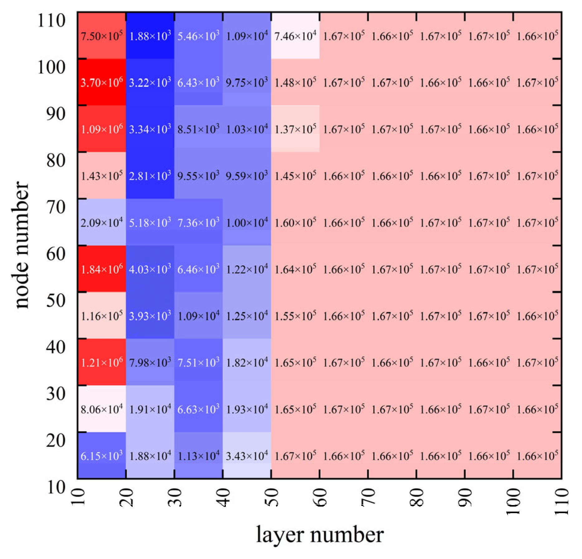
To improve the performance and avoid overfitting, the MSEs of multiple FNN Models were evaluated at different numbers of hidden layer nodes and layers. The results of this analysis are presented in
Figure 6. The FNN Model showed higher performance when the hidden layer was set to 70 nodes and 20 layers.
Activation functions can introduce nonlinear transformations to enhance the expression of the FNN and improve its performance of the FNN Model. To obtain the appropriate activation functions, activation functions including PReLU, sigmoid, and tanh were compared, as shown in
Table 2. We can observe that the PReLU function exhibits higher performance with a smaller MSE.
3. Implementation
All computations in this section were performed using Python 3.9.19 with the NumPy 1.26.4, SciPy 1.13.1, and PyTorch 2.4 packages. To ensure experimental reproducibility, the random seed was set to 0. In the scanning method, the divergence angle was set to 70 μrad.
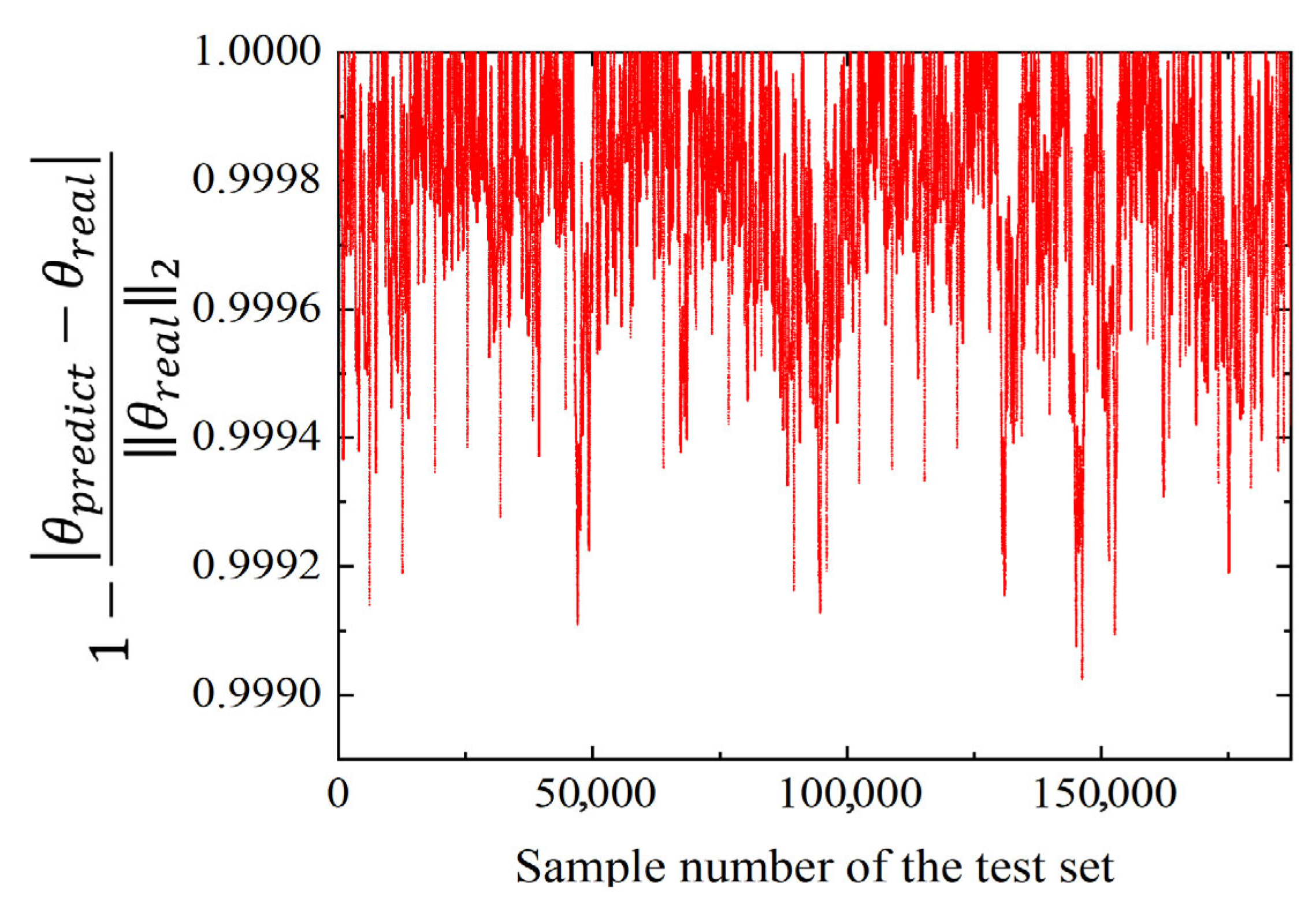
The FNN model converged within 200 steps, achieving a mean square error (MSE) of 0.117 μrad. The accuracy of the FNN Model is illustrated in
Figure 7, where
θpredict denotes the predicted values and
θreal represents the corresponding test set sample data. As shown, the prediction accuracy of the FNN Model exceeded 99.9%.
The predicted errors of the FNN Model are presented in
Figure 8. We can observe that most of the predicted errors in azimuth are between −60 μrad and 100 μrad while the predicted errors in elevation are between −30 μrad and 60 μrad. Compared with the original pointing errors, the adjusted pointing errors were reduced by an order of magnitude.
The trajectory of the scanning step, obtained by combining the pointing error predicted by the FNN Model with an equal linear velocity spiral scanning function, is shown in
Figure 9. The uncertainty cone is at 0.6 mrad while the whole pointing error is below 1 mrad. In order to show the original and adjusted scanning trajectory curves clearly, a smaller coordinate axis range is set in
Figure 9.
4. Experimental Verification
To verify the accuracy of the Model, the predicted results were compared with telemetry data, which were obtained during the bidirectional stable laser communication of an L-ISL based on on-orbit commercial satellites.
4.1. Precision of the FNN Model
The predicted results and real pointing errors obtained from the actual telemetry data are shown in
Figure 10. The Pearson correlation coefficients between the predicted results and actual telemetry data were 99.85% and 98.42%.
Based on the above analysis and discussion, the error distribution of the calculated pointing error using the proposed algorithm is shown in
Figure 11. As can be seen from
Figure 11, the median calculation error of the elevation, azimuth, and combined pointing error is 2.0448 μrad, 13.1691 μrad, and −9.3123 μrad, respectively, while 75% of the error is within 50 μrad. Since the field of view is 600 μrad, the pointing error can meet the requirement.
4.2. Success Rate of the Acquisition Process
As pointing errors can be predicted, the acquisition process has greater potential to improve its success rate. To verify this improvement, a single step of the proposed acquisition process was compared with the traditional acquisition method using actual telemetry data, as described in
Figure 12. The results show that the novel acquisition process achieves a success rate of over 90% within an uncertainty cone of 100 µrad—an improvement that is eight times higher than that of the traditional acquisition process.
Considering that the acquisition process took 5 min, the success rates of both methods are shown in
Figure 13. The success rate of the novel acquisition process is higher than that of the traditional acquisition process when the uncertainty cone is below 3 mrad.
4.3. Speed of the Acquisition Process
To verify the speed of the acquisition process, the time required to achieve different success rates was analyzed using telemetry data, as shown in
Figure 14. We can observe that the novel acquisition process can achieve a 90% success rate in 0.1 s, while the traditional acquisition process needs 32 s. Therefore, the acquisition process was accelerated by more than 300 times.
5. Discussion
To evaluate the effectiveness of the FNN Model at different frequencies induced by temperature and vibration, the pointing errors were analyzed using Fourier coordinates. Because the pointing error is influenced by multiple factors, its amplitude in the Fourier domain is smaller than in the time domain. As shown in
Figure 15a,b, the FNN Model demonstrates better performance in reducing elevation errors compared to azimuth errors. This is attributed to the larger initial pointing errors in the azimuth direction, which provide greater potential for optimization. Additionally,
Figure 15c,d show that the original pointing error exhibited a periodicity of 27 s, whereas the adjusted pointing error no longer displays this periodic behavior. This phenomenon may be related to the specific settings of the laser terminal on the satellite.
6. Conclusions
This paper proposes a novel acquisition process that leverages a FNN Model to establish the relationship between satellite orbital parameters and pointing errors in both azimuth and elevation. To evaluate the performance of the FNN Model, the predicted results were compared with on-orbit telemetry data. By integrating the predicted pointing errors with a spiral scanning function, the acquisition process was accelerated by more than 300 times, while the success rate increased by a factor of 8. The FNN Model proved effective in scenarios involving multiple influencing factors. Moreover, the potential of reinforcement learning and the feasibility of achieving full automation warrant further investigation.
Author Contributions
Conceptualization, X.L. (Xiangnan Liu); software, X.L. (Xiangnan Liu); validation, Z.D. and H.S.; formal analysis, X.L. (Xiangnan Liu); writing—original draft preparation, X.L. (Xiangnan Liu); writing—review and editing, X.L. (Xiangnan Liu); supervision, X.L. (Xiaoping Li); project administration, X.L. (Xiangnan Liu) and X.L. (Xiaoping Li); funding acquisition, X.L. (Xiaoping Li). All authors have read and agreed to the published version of the manuscript.
Funding
This work was supported by the National Natural Science Foundation of China (Nos. 52205576), Optoelectronic Measurement and Intelligent Perception Zhongguancun Open Lab (No. LabSOMP-2023-04), and State Key Laboratory for Manufacturing Systems Engineering (Grant No. klms2021005).
Data Availability Statement
All the data used in this article can be obtained from the author upon reasonable request.
Conflicts of Interest
The authors declare no conflicts of interest.
References
- Duarte, V.C.; Prata, J.G.; Ribeiro, C.F.; Nogueira, R.N.; Winzer, G.; Zimmermann, L.; Walker, R.; Clements, S.; Filipowicz, M.; Napierała, M.; et al. Modular coherent photonic-aided payload receiver for communications satellites. Nat. Commun. 2019, 10, 1984. [Google Scholar] [CrossRef] [PubMed]
- Walsh, S.M.; Karpathakis, S.F.E.; McCann, A.S.; Dix-Matthews, B.P.; Frost, A.M.; Gozzard, D.R.; Gravestock, C.T.; Schediwy, S.W. Demonstration of 100 Gbps coherent free-space optical communications at LEO tracking rates. Sci. Rep. 2022, 12, 18345. [Google Scholar] [CrossRef] [PubMed]
- Horst, Y.; Bitachon, B.I.; Kulmer, L.; Brun, J.; Blatter, T.; Conan, J.-M.; Montmerle-Bonnefois, A.; Montri, J.; Sorrente, B.; Lim, C.B.; et al. Tbit/s line-rate satellite feeder links enabled by coherent modulation and full-adaptive optics. Light Sci. Appl. 2023, 12, 153. [Google Scholar] [CrossRef] [PubMed]
- Riesing, K.M.; Schieler, C.M.; Chang, J.S.; Gilbert, N.J.; Horvath, A.J.; Reeve, R.S.; Robinson, B.S.; Wang, J.P.; Agrawal, P.S.; Goodloe, R.A. On-orbit results of pointing, acquisition, and tracking for the TBIRD CubeSat mission. Proc. SPIE 2023, 12413, 1241302. [Google Scholar]
- Liu, Y.; Li, X.; Li, D.; Zhao, C.; Huang, S. Green laser inter-satellite link planning in satellite optical networks: Trading off the battery lifetime and network throughput using numerical quantization. J. Opt. Commun. Netw. 2024, 16, 868–880. [Google Scholar] [CrossRef]
- Wang, G.; Yang, F.; Song, J.; Han, Z. Free Space Optical Communication for Inter-Satellite Link: Architecture, Potentials and Trends. IEEE Commun. Mag. 2024, 62, 110–116. [Google Scholar] [CrossRef]
- Hou, X.; Liu, Z.; Chang, Y. Analysis on Development Status and Trend of Space Laser Communication Technology. Chin. J. Lasers 2024, 51, 1101013. [Google Scholar]
- Hauschildt, H.; Le Gallou, N.; Mezzasoma, S.; Moeller, H.L.; Armengol, J.P.; Witting, M.; Herrmann, J.; Carmona, C.; Karafolas, N.; Sodnik, Z.; et al. Global Quasi-Real-Time-Services back to Europe: EDRS Global. Proc. SPIE 2018, 11180, 353–357. [Google Scholar]
- Brashears, T.R. Achieving ≳99% link uptime on a fleet of 100G space laser inter-satellite links in LEO. Proc. SPIE 2024, 12877, 1287702. [Google Scholar]
- Younus, O.I.; Riaz, A.; Binns, R.; Scullion, E.; Wicks, R.; Vernon, J.; Graham, C.; Bramall, D.; Schmoll, J.; Bourgenot, C. Overview of Space-Based Laser Communication Missions and Payloads: Insights from the Autonomous Laser Inter-Satellite Gigabit Network (ALIGN). Aerospace 2025, 11, 907. [Google Scholar] [CrossRef]
- Toyoshima, M. Recent Trends in Space Laser Communications for Small Satellites and Constellations. J. Light. Technol. 2021, 39, 693–699. [Google Scholar] [CrossRef]
- AlQuwaiee, H.; Yang, H.C.; Alouini, M.S. On the Asymptotic Capacity of Dual-Aperture FSO Systems with Generalized Pointing Error Model. IEEE Trans. Wirel. Commun. 2016, 15, 6502–6512. [Google Scholar] [CrossRef]
- Ansari, I.S.; Yilmaz, F.; Alouini, M.S. Performance Analysis of Free-Space Optical Links Over Malaga (M) Turbulence Channels with Pointing Errors. IEEE Trans. Wirel. Commun. 2016, 15, 91–102. [Google Scholar] [CrossRef]
- Bashir, M.S.; Bell, M.R. Optical Beam Position Tracking in Free-Space Optical Communication Systems. IEEE Trans. Aerosp. Electron. Syst. 2018, 54, 520–536. [Google Scholar] [CrossRef]
- Zou, Y.; Ke, Z.; Shao, Y.; Fan, Q.; Liu, C. Short-distance equivalent test of acquisition, pointing, and tracking process for space laser communication. Appl. Opt. 2022, 61, 721–727. [Google Scholar] [CrossRef]
- Yu, Z.; Zhao, Y.; Yuan, D. Robust Divergence Angle for Inter-Satellite Laser Communications under Target Deviation Uncertainty. In Proceedings of the 2023 IEEE 98th Vehicular Technology Conference, Hong Kong, China, 10–13 October 2023. [Google Scholar]
- Moon, H.J.; Chae, C.B.; Wong, K.K.; Alouini, M.S. Pointing-and-Acquisition for Optical Wireless in 6G: From Algorithms to Performance Evaluation. IEEE Commun. Mag. 2023, 62, 32–38. [Google Scholar] [CrossRef]
- Bashir, M.S.; Alouini, M.S. Adaptive Acquisition Schemes for Photon-Limited Free-Space Optical Communications. IEEE Trans. Commun. 2021, 69, 416–428. [Google Scholar] [CrossRef]
- Bashir, M.S.; Alouini, M.S. Signal Acquisition with Photon-Counting Detector Arrays in Free-Space Optical Communications. IEEE Trans. Wirel. Commun. 2020, 19, 2181–2195. [Google Scholar] [CrossRef]
- Hu, S.; Zhang, R.; Xu, Y.; Hu, Z.; Ben, L.; Shi, C.; Xu, X. Convex optimization acquisition model with in-orbit jitter for inter-satellite laser communication. Proc. SPIE 2023, 12617, 490–496. [Google Scholar]
- Lee, K.; Mai, V.; Kim, H. Acquisition Time in Laser Inter-Satellite Link Under Satellite Vibrations. IEEE Photonics J. 2023, 15, 7303009. [Google Scholar] [CrossRef]
- Liu, X.; Meng, Y. Bidirectional scanning acquisition of inter-satellite laser links for space gravitational wave detection mission. Rev. Sci. Instrum. 2024, 95, 114502. [Google Scholar] [CrossRef] [PubMed]
- Shi, Y.; Chen, S.; Yu, M.; Wu, Y.; Yu, J.; Zhang, L. Thermal Deformation Stability Optimization Design and Experiment of the Satellite Bus to Control the Laser Communication Load’s Acquisition Time. Appl. Sci. 2023, 13, 5502. [Google Scholar] [CrossRef]
- Gelvez-Almeida, E.; Mora, M.; Barrientos, R.J.; Hernández-García, R.; Vilches-Ponce, K.; Vera, M.A. Review on Large-Scale Data Processing with Parallel and Distributed Randomized Extreme Learning Machine Neural Networks. Math. Comput. Appl. 2024, 29, 40. [Google Scholar] [CrossRef]
- Muñoz-Zavala, A.E.; Macías-Díaz, J.E.; Alba-Cuéllar, D.; Guerrero-Díaz-De-León, J.A. A Literature Review on Some Trends in Artificial Neural Networks for Modeling and Simulation with Time Series. Algorithms 2024, 17, 76. [Google Scholar] [CrossRef]
- Agharafeie, R.; Ramos, J.R.C.; Mendes, J.M.; Oliveira, R. From Shallow to Deep Bioprocess Hybrid Modeling: Advances and Future Perspectives. Fermentation 2023, 9, 922. [Google Scholar] [CrossRef]
- Guiomar, F.P.; Fernandes, M.A.; Nascimento, J.L.; Rodrigues, V.; Monteiro, P.P. Coherent Free-Space Optical Communications: Opportunities and Challenges. J. Light. Technol. 2022, 40, 3173–3186. [Google Scholar] [CrossRef]
| Disclaimer/Publisher’s Note: The statements, opinions and data contained in all publications are solely those of the individual author(s) and contributor(s) and not of MDPI and/or the editor(s). MDPI and/or the editor(s) disclaim responsibility for any injury to people or property resulting from any ideas, methods, instructions or products referred to in the content. |
© 2025 by the authors. Licensee MDPI, Basel, Switzerland. This article is an open access article distributed under the terms and conditions of the Creative Commons Attribution (CC BY) license (https://creativecommons.org/licenses/by/4.0/).


