Article

Cascaded Quasi-Resonant Extended State Observer-Based Deadbeat Predictive Current Control Strategy for PMSM

Chengdu Aircraft Industrial (Group) Co., Ltd., Chengdu 610092, China
*
Author to whom correspondence should be addressed.
Electronics 2025, 14(14), 2782; https://doi.org/10.3390/electronics14142782
Submission received: 10 May 2025 / Revised: 26 June 2025 / Accepted: 8 July 2025 / Published: 10 July 2025
(This article belongs to the Special Issue Control of Power Quality and System Stability)

Abstract

The traditional deadbeat predictive current control (DPCC) strategies for a permanent magnet synchronous motor (PMSM), such as those based on an extended state observer (ESO) and quasi-resonant extended state observer (QRESO), usually require large observer bandwidth, rendering the system sensitive to noise. To address this issue, this paper proposes a cascaded quasi-resonant extended state observer-based DPCC (CQRESO-based DPCC) strategy. Specifically, the CQRESO is utilized to estimate the predicted values of d-axis and q-axis currents, as well as the system total disturbance caused by the deterministic and uncertain factors at time instant k + 1. Subsequently, the required control command voltage at time instant k + 1 is then calculated according to the deadbeat control principle. Finally, the comparative simulation results with ESO-based DPCC and QRESO-based DPCC strategies demonstrate that the proposed strategy can achieve dynamic and robust performance comparable to the ESO-based and QRESO-based DPCC strategies while utilizing a smaller observer bandwidth. Additionally, it exhibits superior steady-state performance and 5th and 7th harmonic current suppression capabilities (in the abc reference frame).

1. Introduction

The electrification of aircraft systems is an inevitable trend in the future development of the aviation industry [1,2]. As one of the core technologies for more electric aircraft (MEA), power by wire (PBW) actuation technology plays a crucial role in flight control, reliability, and maintainability [1,2,3,4]. Currently, there are two main implementations of PBW as follows: electro-mechanical actuators (EMA) and electro-hydrostatic actuators (EHA). For both EHA and EMA, the core challenge lies in the precise control of actuation motors. The accuracy of motor control directly affects the working performance of the actuation system and the aircraft’s flight quality. Therefore, it is of great importance to develop a high-performance control strategy for the actuation motor of MEA and EHA.
Compared with other kind of motor types, the permanent magnet synchronous motor (PMSM) offers many advantages such as small size, high power density, and superior efficiency [3,4,5,6,7], making it widely adopted in EHA and EMA. In addition, the PMSM has also been used in the starter/generator system of MEA [8,9,10,11] and other industrial applications, such as electric vehicles, large-aperture telescopes, subway, high-speed railway, etc. [5,12]. For the PMSM, the commonly adopted control strategy is a dual closed-loop structure incorporating the following: a speed outer loop and a current inner loop [4,5,6,7,13,14,15,16,17,18]. The current loop, as the inner control layer, critically determines the overall system control performance. A fast-response current loop can not only improve current tracking accuracy but it can also enhance outer-loop control performance [12,13,14]. At present, the proportional-integral (PI) controller remains the most widely adopted control method for the current loop of a PMSM. Though the PI controller offers many advantages, such as simple structure and ease of implementation, it also presents some drawbacks, including phase lag and limited dynamic performance [10,11,12,13,16]. Furthermore, the PI controller cannot suppress harmonic currents generated by the inverter dead-time effects, motor flux harmonics, cogging torque, and current sampling errors in PMSM drive systems [12,16,17,18]. The presence of harmonic currents can lead to an increase in motor losses and torque ripple, which deteriorate system control performance and may even shorten a motor’s service life [12,16,17,18].
To avoid complex control parameter tuning processes and improve system dynamic response performance, some researchers have introduced the idea of deadbeat control to the current inner loop of a PMSM [7,13,14]. The deadbeat predictive current control (DPCC) strategy calculates the optimal control voltages based on the PMSM’s mathematical model within each sampling period, enabling a fast dynamic response and ensuring the stator current to track its reference value in the next sampling cycle [13,14,19]. However, such a method heavily relies on accurate motor electrical parameters. In practice, parameter variations caused by measurement errors, environmental factors, operational conditions, and component aging will inevitably degrade the DPCC’s control performance, leading to current tracking inaccuracies or even system instability [7,13,14]. Moreover, the conventional DPCC strategy cannot effectively suppress stator current harmonics (appearing as 6k-order harmonics in d-axis and q-axis current in the dq synchronous rotating reference frame and appearing as 6k ± 1-order harmonics in the abc reference frame). In order to enhance the DPCC’s robustness, the extended state observer (ESO)-based DPCC strategies, in which the ESO is employed, replaces the PMSM’s mathematical model to estimate d-axis and q-axis currents and system total disturbances at time instant k + 1, and the required control voltage at time instant k + 1 is then calculated based on deadbeat control principle [13,14]. Such a control strategy can improve system robustness against the parameter variations, but it still fails to suppress current harmonics effectively. For the aim of enhancing DPCC’s robustness and harmonic suppression performance, the quasi-resonant extended state observer (QRESO) can be employed to estimate the predictive value of the current and the system’s total disturbance [17,18,19,20]. However, it should be noted that both ESO-based and QRESO-based DPCC strategies require a large observer bandwidth for rapid current regulation, which increases the sensitivity to measurement noise.
Recently, in order to improve system control performance, several control strategies based on different kind of cascade observers have been proposed for the current inner loop and speed outer loop of the PMSM’s control system [12,21,22]. In [12], an improved ADRC with a CESO based on a quasi-generalized integrator is proposed to attenuate the periodic and aperiodic disturbance in the current inner loop. In [21], an enhanced linear active disturbance rejection control (ADRC)-based high-frequency pulse voltage signal injection strategy, where the cascade linear ESO is established to estimate the total disturbance, is proposed for speed outer loop to improve control performance in the presence of the disturbance. In [22], a cascaded linear–nonlinear ADRC strategy, in which the cascaded linear–nonlinear ESO is designed to estimate and compensate for the uncertain disturbances, is proposed for the speed outer control loop of the PMSM to improve anti-disturbance performance and speed tracking performance. Despite the significant research progress for cascade observer-based control strategies to improve the control performance of a PMSM, it seems that no attempt has been made to enhance the system’s dynamic performance and noise rejection ability for a PMSM by utilizing a cascaded quasi-resonant extended state observer (CQRESO) in conjunction with the principle of deadbeat predictive control.
Motivated by the demands and issues mentioned above, this paper mainly contributes to propose a cascaded quasi-resonant extended state observer-based DPCC (CQRESO-based DPCC) strategy for the current loop of the PMSM. The proposed method utilizes CQRESO to estimate the predicted values of d-axis and q-axis currents as well as the system total disturbance caused by the deterministic and uncertain factors at time instant k + 1, and the required d-axis and q-axis command voltage is then calculated based on the deadbeat predictive control principle. Since the CQRESO can track the disturbance with a relatively smaller bandwidth compared to the conventional single ESO and QRESO, the proposed CQRESO-based DPCC strategy is more immune to measurement noise compared to the ESO-based and QRESO-based DPCC methods, while ensuring the similar robustness and dynamic performance. Additionally, the proposed control method also exhibits superior steady-state performance and 5th and 7th current harmonic suppression capability (in the abc reference frame) from the simulation results.
The subsequent sections of the paper are organized as follows. Section 2 presents the mathematical model of the PMSM, considering the periodic and aperiodic disturbances. In Section 3, the design principle of the proposed CQRESO-based DPCC strategy is presented. In Section 4, the proposed control strategy is compared and analyzed with ESO-based DPCC and QRESO-based DPCC strategy by simulation, and the comparison simulation results verify the feasibility and effectiveness of the proposed control strategy. Finally, the conclusions are summarized in Section 5.

2. Mathematical Model of the PMSM Considering Disturbance

Ideally, the state equation of the PMSM’s stator currents in the dq reference frame can be expressed as follows [7,12,13,14,16]:
d d t i d = 1 L d u d R s L d i d + ω e L q L d i q d d t i q = 1 L q u q R s L q i q ω e L d L q i d 1 L q ω e ψ f
where id and iq represent the d-axis and q-axis stator current, respectively; ud and uq represent the d-axis and q-axis stator voltage, respectively; Ld and Lq represent the d-axis and q-axis stator winding inductance, respectively; Rs is the stator winding resistance; ω e is the rotor electrical angular speed; and ψ f is the rotor flux. For the surface-mounted PMSM adopted in this paper, it satisfies Ld = Lq = Ls, where Ls is the stator winding inductance.
However, during actual operation, PMSM will inevitably suffer from periodic and aperiodic disturbances due to circuit parameter perturbations, flux harmonics, inverter nonlinearity, unbalanced phase impedance, and dead-time effects [12,16]. When considering these system disturbances, the state equation of a PMSM’s stator currents in the dq reference frame can be presented as follows [12,16]:
d d t i d = b 0 u d + f d d d t i q = b 0 u q + f q
where b0 = 1/Ls0, and Ls0 are the nominal values of stator winding inductance; and fd and fq represent the d-axis and q-axis total disturbances, respectively. fd and fq can be expressed as follows:
f d = f d a p + f d p f q = f q a p + f q p f d a p = ω e i q R s 0 L s 0 i d + Δ L d d i d d t Δ R s i d + ω e Δ L q i q / L s 0 + f d e x f d p = 1 L s 0 4 T d U d c π T s k = 1 12 k 36 k 2 1 sin 6 k ω e t + ω e k = 1 ψ d 6 k h cos 6 k ω e t f d a p = ω e i d R s 0 L s 0 i q ω e L s 0 ψ f 0 + Δ L q d i q d t Δ R s i q ω e Δ L d i d ω e Δ ψ f / L s 0 + f q e x f d p = 1 L s 0 4 T d U d c π T s 1 + k = 1 2 36 k 2 1 cos 6 k ω e t ω e k = 1 ψ d 6 k h sin 6 k ω e t
where fdp and fdap represent the d-axis periodic and aperiodic disturbances, respectively; fqp and fqap represent the q-axis periodic and aperiodic disturbances, respectively; and Δ L d = L d L s 0 , Δ L q = L q L s 0 , Δ R s = R s R s 0 and Δ ψ f = ψ f ψ f 0 represent the parameter errors deviation between the nominal value and their actual values. L s 0 , R s 0 , and ψ f 0 represent the corresponding nominal parameters; fdex and fqex represent the other unknown external disturbances in the d-axis and q-axis, respectively; Td is the dead-time of pulse width modulation (PWM); Ts is the system control period; Udc is the DC-side voltage of the inverter; and k is the harmonic order.

3. Proposed CQRESO-Based DPCC Strategy

For the aim of reducing the current loop control system’s sensitivity to noise while balancing the current regulation’s dynamic performance, steady-state characteristics and their robustness against the circuit parameters’ variations, this subsection proposes a CQRESO-based DPCC strategy. The principle of CQRESO is firstly introduced, and based on this, the CQRESO is designed to estimate the d-axis, q-axis currents, and system total disturbances at time instant k + 1. Subsequently, the CQRESO is integrated with DPCC to form a composite controller, namely, the CQRESO-based DPCC strategy, which can achieve steady-state error-free current control. The specific details are as follows.

3.1. Principles of the CQRESO

Taking a first-order single-input single-output system with disturbances as an example.
x ˙ = b 0 u + f x , w ( t ) , t y = x
where x is the state variable; b0 is the control gain; u and y represent the system input and output; w ( t ) is the system’s external disturbance; and f x , w ( t ) , t is the system’s total disturbance.
By extending system total disturbance f x , w ( t ) , t as a new state, Equation (4) can be rewritten as follows:
x ˙ 1 = b 0 u + x 2 x ˙ 2 = h y = x 1
where x1 = x, x2 = f x , w ( t ) , t , and h represents the derivative of x2.
According to Equation (5), the QRESO can be designed as follows [17,18,19,20]:
e = x 1 x ^ 1 x ^ ˙ 1 = b 0 u + x ^ 2 + β 1 e x ^ ˙ 2 = β 2 e + β 2 R ( t ) e ˙
where e is the estimation error of x1; and x ^ 1 and x ^ 2 are the estimated values of state variables x1 and x2, respectively. β 1 and β 2 are the gains of QRESO, which can be designed as 2 ω 0 and ω 0 2 , where ω 0 is the bandwidth of the observer [23,24,25,26]. R(t) is the time-domain expression for a quasi-resonant controller, and its transfer function in the s-domain is given by the following:
R ( s ) = 2 k r ω c s s 2 + 2 ω c s + ω r
where kr is the resonant gain; ω c is the cut-off frequency; and ω r represents the selective resonant frequency.
Usually, a single QRESO has limited disturbance observation capabilities. That is, a larger observer bandwidth is required for the observer to achieve accurate and rapid estimation of disturbances, which makes the system sensitive to noise. To solve this issue, this paper proposes a cascaded QRESO structure incorporating two QRESOs in series to enhance the estimation capability for both periodic and aperiodic disturbances, as illustrated in Figure 1.
As shown in Figure 1, the CQRESO first performs a preliminary estimation of the system’s total disturbance through QRESO1, obtaining the initial estimated value of the total disturbance x ^ 21 . This obtained initial estimation x ^ 21 is then fed into QRESO2 as the known disturbance component. Subsequently, QRESO2 observes the remaining unestimated disturbances to derive the estimated value x ^ 22 . Finally, the total estimated system disturbance x ^ 2 is synthesized by combining these two estimations, that is, x ^ 2 = x ^ 21 + x ^ 22 . The mathematical expressions for QRESO1 and QRESO2 are, respectively, given as follows:
QRESO 1 :   x ^ ˙ 11 = b 0 u + x ^ 21 + β 11 ( x 1 x ^ 11 ) x ^ ˙ 21 ( 0 ) = β 21 ( x 1 x ^ 11 ) x ˙ 31 = β 21 ( x 1 x ^ 11 ) 2 ω c 1 x 31 ω r 1 2 x 41 x ˙ 41 = x 31 x ^ ˙ 21 ( ω r ) = 2 k r 1 ω c 1 x 31 x ^ 21 = x ^ 21 ( 0 ) + x ^ 21 ( ω r )
QRESO 2 :   x ^ ˙ 12 = b 0 u + x ^ 22 + x ^ 21 + β 12 ( x 1 x ^ 12 ) x ^ ˙ 22 ( 0 ) = β 22 ( x 1 x ^ 12 ) x ˙ 32 = β 22 ( x 1 x ^ 12 ) 2 ω c 2 x 32 ω r 2 2 x 42 x ˙ 42 = x 32 x ^ ˙ 22 ( ω r ) = 2 k r 2 ω c 2 x 32 x ^ 22 = x ^ 22 ( 0 ) + x ^ 22 ( ω r )
where x ^ 11 is the estimated value of state variable x1 by QRESO1; x ^ 12 is the estimated value of the state variable x1 by QRESO2; β 11 and β 21 are the gains of QRESO1; β 12 and β 22 are the gains of QRESO2; x 31 and x 41 are the intermediate state variables in QRESO1; x 32 and x 42 are the intermediate state variables in QRESO2; x ^ 21 ( 0 ) and x ^ 21 ( ω r ) are the estimated values of aperiodic and periodic disturbances by QRESO1, respectively; x ^ 22 ( 0 ) and x ^ 22 ( ω r ) are the estimated values of the unestimated aperiodic and periodic disturbances in QRESO1 by QRESO2, respectively; and k r 1 , ω c 1 , and ω r 1 and k r 2 , ω c 2 , and ω r 2 are the proportional coefficients of the resonant terms, cutoff frequencies, and resonant angular frequencies of the quasi-resonant controllers in QRESO1 and QRESO2, respectively.

3.2. CQRESO-Based DPCC Strategy

To facilitate the subsequent analysis and design, we assume that x ( k 1 ) , x ( k ) , x ( k + 1 ) , and x ( k + 2 ) denote the values of the physical quantity x at time instant k 1 , k, k + 1 , and k + 2 , respectively. By using the forward Euler method to discretize Equation (2), the following equation can be obtained [13,14,19]:
i d ( k + 1 ) = i d ( k ) + b 0 u d ( k ) T s + f d ( k ) T s i q ( k + 1 ) = i q ( k ) + b 0 u q ( k ) T s + f q ( k ) T s
In practical control systems, there always exists a one-step delay due to sampling, control algorithm computation, and control output execution, and the command voltage calculated at time instant k becomes effective at time instant k + 1. To address this issue, this paper adopts a two-step prediction strategy for delay compensation [13,14,19]. Specifically, Equation (10) is advanced by one sampling period, while setting the current at time instant k + 2 as the reference current. Subsequently, the control command voltage expression at time instant k + 1 considering the system disturbances can be derived as follows:
u d r e f ( k + 1 ) = i d r e f i d ( k + 1 ) b 0 T s f d ( k + 1 ) b 0 u q r e f ( k + 1 ) = i q r e f i q ( k + 1 ) b 0 T s f q ( k + 1 ) b 0
where u d r e f and u q r e f represent the d-axis and q-axis deadbeat command voltages, respectively; and i d r e f and i q r e f denote the d-axis and q-axis reference currents, respectively.
As evident from the aforementioned analysis, the key to designing a DPCC strategy lies in accurately predicting the d-axis and q-axis stator currents ( i d ( k + 1 ) , i q ( k + 1 ) ) and system total disturbances ( f d ( k + 1 ) , f d ( k + 1 ) ) at time instant k + 1. In this paper, the CQRESO is designed to predict both the stator currents and the system’s total disturbances in the d-axis and q-axis at time instant k + 1.
According to the design concept of CQRESO, the d-axis voltage ud and q-axis voltage uq can be considered as the input of the d-axis and q-axis subsystems, respectively. The d-axis current id and q-axis current iq can be considered as the state variables and output of the d-axis and q-axis subsystems, respectively. By expanding system total disturbance fd and fq as the new state variables corresponding to the subsystem, the following expression can be obtained to describe the d- and q-axis subsystems:
d-axis subsystem:
d d t i d = b 0 u d + f d f ˙ d = h d
where hd is the derivative of fd.
q-axis subsystem:
d d t i q = b 0 u q + f q f ˙ q = h q
where hq is the derivative of fq.
To estimate id, iq, fd, and fq, the CQRESO of the d-axis and q-axis subsystems can be constructed based on the model shown in Equations (12) and (13) as follows:
d-axis subsystem:
QRESO 1 : i ^ ˙ d 1 = b d 0 u d + f ^ d 1 + β d 11 ( i d i ^ d 1 ) f ^ ˙ d 1 ( 0 ) = β d 12 ( i d i ^ d 1 ) x ˙ d 13 = β d 12 ( i d i ^ d 1 ) 2 ω d c 1 x d 13 ω d r 1 2 x d 14 x ˙ d 14 = x d 13 f ^ ˙ d 1 ( ω r ) = 2 k d r 1 ω d c 1 x d 13 f ^ d 1 = f ^ d 1 ( 0 ) + f ^ d 1 ( ω r )
  QRESO 2 :   i ^ ˙ d 2 = b d 0 u d + f ^ d 1 + f ^ d 2 + β d 21 ( i d i ^ d 2 ) f ^ ˙ d 2 ( 0 ) = β d 22 ( i d i ^ d 2 ) x ˙ d 23 = β d 22 ( i d i ^ d 2 ) 2 ω d c 2 x d 23 ω d r 2 2 x d 24 x ˙ d 24 = x d 23 f ^ ˙ d 2 ( ω r ) = 2 k d r 2 ω d c 2 x d 23 f ^ d 2 = f ^ d 2 ( 0 ) + f ^ d 2 ( ω r )
where i ^ d 1 and i ^ d 2 are the estimated values of the d-axis current by QRESO1 and QRESO2, respectively; f ^ d 1 is the estimated total disturbance of the d-axis subsystem by QRESO1; f ^ d 2 is the unestimated total disturbance of the d-axis subsystem from QRESO1 by QRESO2; β d 11 and β d 12 are the gains of QRESO1; β d 21 and β d 22 , are the gains of QRESO2; x d 13 and x d 14 are the intermediate state variables of QRESO1; x d 23 and x d 24 are the intermediate state variables of QRESO2; f ^ d 1 ( 0 ) and f ^ d 1 ( ω r ) are the estimated aperiodic and periodic disturbances by QRESO1, respectively; f ^ d 2 ( 0 ) and f ^ d 2 ( ω r ) are the unestimated aperiodic and periodic disturbances from QRESO1 by QRESO2, respectively; k d r 1 , ω d c 1 , and ω d r 1 and k d r 2 , ω d c 2 , and ω d r 2 are the proportional resonant term coefficient, cutoff frequency, and resonant angular frequency of the quasi-resonant regulators in QRESO1 and QRESO2, respectively; ud is replaced with the calculated deadbeat command voltage of the d-axis u d r e f during algorithm implementation to reduce motor drive system costs; and ω d r 1 and ω d r 2 are set to be six times the electrical angular velocity ω e to suppress the 6th harmonic component of the d-axis stator current.
q-axis subsystem:
QRESO 1 :   i ^ ˙ q 1 = b q 0 u q + f ^ q 1 + β q 11 ( i q i ^ q 1 ) f ^ ˙ q 1 ( 0 ) = β q 12 ( i q i ^ q 1 ) x ˙ q 13 = β q 12 ( i q i ^ q 1 ) 2 ω q c 1 x q 13 ω q r 1 2 x q 14 x ˙ q 14 = x q 13 f ^ ˙ q 1 ( ω r ) = 2 k q r 1 ω q c 1 x q 13 f ^ q 1 = f ^ q 1 ( 0 ) + f ^ q 1 ( ω r )
  QRESO 2 : i ^ ˙ q 2 = b q 0 u q + f ^ q 1 + f ^ q 2 + β q 21 ( i q i ^ q 2 ) f ^ ˙ q 2 ( 0 ) = β q 22 ( i q i ^ q 2 ) x ˙ q 23 = β q 22 ( i q i ^ q 2 ) 2 ω q c 2 x q 23 ω q r 2 2 x q 24 x ˙ q 24 = x q 23 f ^ ˙ q 2 ( ω r ) = 2 k q r 2 ω q c 2 x q 23 f ^ q 2 = f ^ q 2 ( 0 ) + f ^ q 2 ( ω r )
where i ^ q 1 and i ^ q 2 are the estimated values of the d-axis current by QRESO1 and QRESO 2, respectively; f ^ q 1 is the estimated total disturbance of d-axis subsystem by QRESO1; f ^ q 2 is the unestimated total disturbance of the d-axis subsystem from QRESO1 by QRESO2; β q 11 and β q 12 are the gains of QRESO1; β q 21 and β q 22 are the gains of QRESO2; x q 13 and x q 14 are the intermediate state variables of QRESO1; x q 23 and x q 24 are the intermediate state variables of QRESO2; f ^ q 1 ( 0 ) and f ^ q 1 ( ω r ) are the estimated aperiodic and periodic disturbances by QRESO1, respectively; f ^ q 2 ( 0 ) and f ^ q 2 ( ω r ) are the unestimated aperiodic and periodic disturbances from QRESO1 by QRESO2, respectively; k q r 1 , ω q c 1 , and ω q r 1 and k q r 2 , ω q c 2 , and ω q r 2 are the proportional resonant term coefficient, cutoff frequency, and resonant angular frequency of the quasi-resonant regulators in QRESO1 and QRESO2, respectively; uq is replaced with the calculated deadbeat command voltage of d-axis u q r e f during algorithm implementation to reduce motor drive system costs; and ω q r 1 and ω q r 2 are set to be six times the electrical angular velocity ω e to suppress the 6th harmonic component of q-axis stator current.
To digitally implement CQRESO, a discrete expression is required. By discretizing Equations (14) and (15) using the forward and backward Euler method, the discrete form of CQRESO for the d-axis subsystem can be obtained as follows:
QRESO 1 : i ^ d 1 ( k + 1 ) = i ^ d 1 ( k ) + b d 0 u d ( k ) T s + f ^ d 1 ( k ) T s + β d 11 T s [ i d ( k ) i ^ d 1 ( k ) ] f ^ d 1 ( 0 ) ( k + 1 ) = f ^ d 1 ( 0 ) ( k ) + β d 12 T s [ i d ( k ) i ^ d 1 ( k ) ] x d 13 ( k + 1 ) = β d 12 T s [ i d ( k ) i ^ d 1 ( k ) ] + ( 1 2 ω d c 1 T s ) x d 13 ( k ) ω d r 1 2 T s x d 14 ( k ) x d 14 ( k + 1 ) = x d 14 ( k ) + x d 13 ( k ) T s f ^ d 1 ( ω r ) ( k + 1 ) = 2 k d r 1 ω d c 1 x d 13 ( k + 1 ) f ^ d 1 ( k + 1 ) = f ^ d 1 ( 0 ) ( k + 1 ) + f ^ d 1 ( ω r ) ( k + 1 )
QRESO 2 : i ^ d 2 ( k + 1 ) = i ^ d 2 ( k ) + b d 0 u d ( k ) T s + f ^ d 1 ( k ) T s + f ^ d 2 ( k ) T s + β d 21 T s [ i d ( k ) i ^ d 2 ( k ) ] f ^ d 2 ( 0 ) ( k + 1 ) = f ^ d 2 ( 0 ) ( k ) + β d 22 T s [ i d ( k ) i ^ d 2 ( k ) ] x d 23 ( k + 1 ) = β d 22 T s [ i d ( k ) i ^ d 2 ( k ) ] + ( 1 2 ω d c 2 T s ) x d 23 ( k ) ω d r 2 2 T s x d 24 ( k ) x d 24 ( k + 1 ) = x d 24 ( k ) + x d 23 ( k ) T s f ^ d 2 ( ω r ) ( k + 1 ) = 2 k d r 2 ω d c 2 x d 23 ( k + 1 ) f ^ d 2 ( k + 1 ) = f ^ d 2 ( 0 ) ( k + 1 ) + f ^ d 2 ( ω r ) ( k + 1 )
By discretizing Equations (16) and (17) using the forward and backward Euler method, the discrete-form of CQRESO for the q-axis subsystem can be obtained as follows:
QRESO 1 : i ^ q 1 ( k + 1 ) = i ^ q 1 ( k ) + b q 0 u q ( k ) T s + f ^ q 1 ( k ) T s + β q 11 T s [ i q ( k ) i ^ q 1 ( k ) ] f ^ q 1 ( 0 ) ( k + 1 ) = f ^ q 1 ( 0 ) ( k ) + β q 12 T s [ i q ( k ) i ^ q 1 ( k ) ] x q 13 ( k + 1 ) = β q 12 T s [ i q ( k ) i ^ q 1 ( k ) ] + ( 1 2 ω q c 1 T s ) x q 13 ( k ) ω q r 1 2 T s x q 14 ( k ) x q 14 ( k + 1 ) = x q 14 ( k ) + x q 13 ( k ) T s f ^ q 1 ( ω r ) ( k + 1 ) = 2 k q r 1 ω q c 1 x q 13 ( k + 1 ) f ^ q 1 ( k + 1 ) = f ^ q 1 ( 0 ) ( k + 1 ) + f ^ q 1 ( ω r ) ( k + 1 )
QRESO 2 : i ^ q 2 ( k + 1 ) = i ^ q 2 ( k ) + b q 0 u q ( k ) T s + f ^ q 1 ( k ) T s + f ^ q 2 ( k ) T s + β q 21 T s [ i q ( k ) i ^ q 2 ( k ) ] f ^ q 2 ( 0 ) ( k + 1 ) = f ^ q 2 ( 0 ) ( k ) + β q 22 T s [ i q ( k ) i ^ q 2 ( k ) ] x q 23 ( k + 1 ) = β q 22 T s [ i q ( k ) i ^ q 2 ( k ) ] + ( 1 2 ω q c 2 T s ) x q 23 ( k ) ω q r 2 2 T s x q 24 ( k ) x q 24 ( k + 1 ) = x q 24 ( k ) + x q 23 ( k ) T s f ^ q 2 ( ω r ) ( k + 1 ) = 2 k q r 2 ω q c 2 x q 23 ( k + 1 ) f ^ q 2 ( k + 1 ) = f ^ q 2 ( 0 ) ( k + 1 ) + f ^ q 2 ( ω r ) ( k + 1 )
By replacing id(k + 1) in Equation (11) with the estimated d-axis current i ^ d 2 ( k + 1 ) at time instant k + 1 from Equation (19), and replacing f d ( k + 1 ) in Equation (11) with the sum of estimated values f ^ d 1 ( k + 1 ) and f ^ d 2 ( k + 1 ) from Equations (18) and (19), the d-axis command voltage under the proposed control method can be derived as
u d r e f ( k + 1 ) = i d r e f i ^ d 2 ( k + 1 ) b 0 T s f ^ d 1 ( k + 1 ) + f ^ d 2 ( k + 1 ) b 0
By replacing iq(k + 1) in Equation (11) with the estimated q-axis current i ^ q 2 ( k + 1 ) at time instant k + 1 from Equation (21), and replacing f q ( k + 1 ) in Equation (11) with the sum of the estimated values f ^ q 1 ( k + 1 ) , f ^ q 2 ( k + 1 ) from Equations (20) and (21), the q-axis command voltage under the proposed control method can be derived as
u q r e f ( k + 1 ) = i q r e f i ^ q 2 ( k + 1 ) b 0 T s f ^ q 1 ( k + 1 ) + f ^ q 2 ( k + 1 ) b 0
Based on the detailed introduction of the proposed CQRESO-based DPCC strategy, its overall control block diagram can be illustrated in Figure 2. In the control system, the speed loop with the PI controller generates the q-axis current reference value i q r e f , while the d-axis current reference is fixed at 0 in this paper. In the current loop, the CQRESO-based DPCC algorithm for the d-axis subsystem and the CQRESO-based DPCC algorithm for the q-axis subsystem, respectively, calculate the d-axis and q-axis command voltages ( u d r e f ( k + 1 ) , u q r e f ( k + 1 ) ). These command voltages then undergo inverse Park transformation and space vector pulse width modulation (SVPWM) before being applied to drive the PMSM through a three-phase inverter.

4. Simulation Results

To verify the effectiveness of the proposed control strategy, a simulation model was built in Matlab/Simulink for validation. Meanwhile, to bring the simulation closer to experimental verification, all constructed systems have been discretized. In the simulation model, the control system’s sampling period (system control period) Ts is set to 100 μs, the PWM’s carrier frequency is set to 10 kHz, and the inverter’s dead time Td is set to 3 μs. The main parameters of the PMSM are shown in Table 1.
To better demonstrate the effectiveness of the proposed control strategy, a comparative analysis is conducted between the proposed strategy and both ESO-based DPCC and QRESO-based DPCC strategies. In the following comparative tests, in order to ensure the fairness of the comparative tests, the speed loops of all three control strategies, we employed the same PI controller, in which proportional coefficient kpv is set to 0.2 and integral coefficient kiv is set to 20. When employing an ESO-based DPCC strategy for the current loop, the observer’s bandwidth is selected as ω0eso = 3000. For the QRESO-based DPCC strategy, the observer’s bandwidth remains identical to that of the ESO-based DPCC strategy, that is, ω0qreso = 3000. In addition, for the quasi-resonant controller parameters in QRESO, the resonant gain kr is set to 0.16 and the cut-off frequency ωc is set to 0.3. For the proposed control strategy, the observer’s bandwidth is determined through trial and error, such that the dynamic performance of the PMSM’s d-axis and q-axis currents during reference tracking can be comparable to that of ESO-based DPCC and QRESO-based DPCC strategies. In this sense, the bandwidth of CQRESO ω0cqreso is set as 1800, and for the quasi-resonant controller parameters in CQRESO, the resonant gains kr1 and kr2 are set to 0.115 and the cut-off frequencies ωc1 and ωc2 are set to 0.3. Figure 3 shows the simulation results of the three control strategies with no load, in which the d-axis and q-axis current reference values step up from 0 A to 3 A. As can be seen from Figure 3, all three control strategies almost exhibit a similar dynamic performance, which can ensure fairness in the subsequent comparisons to some extent.

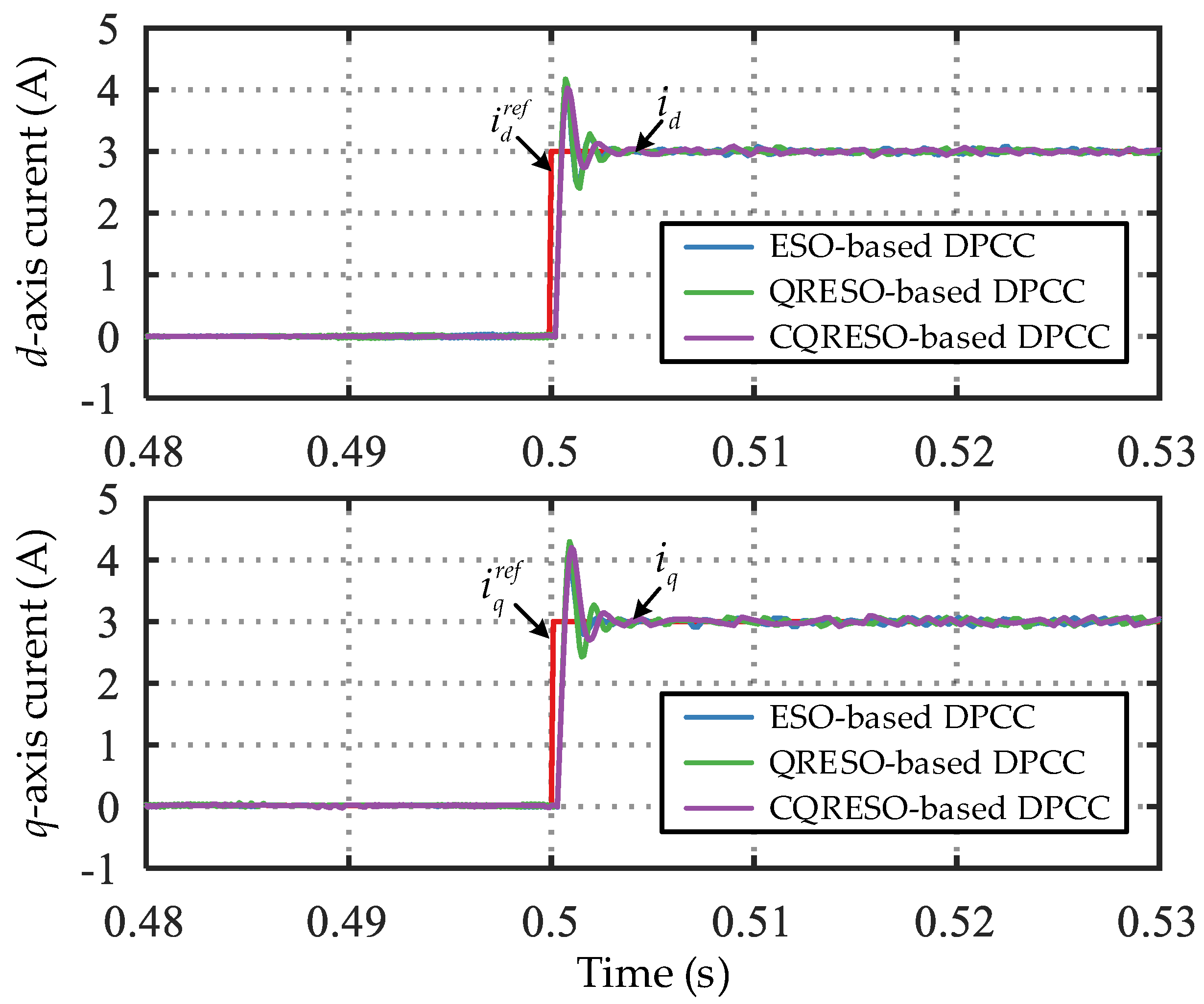
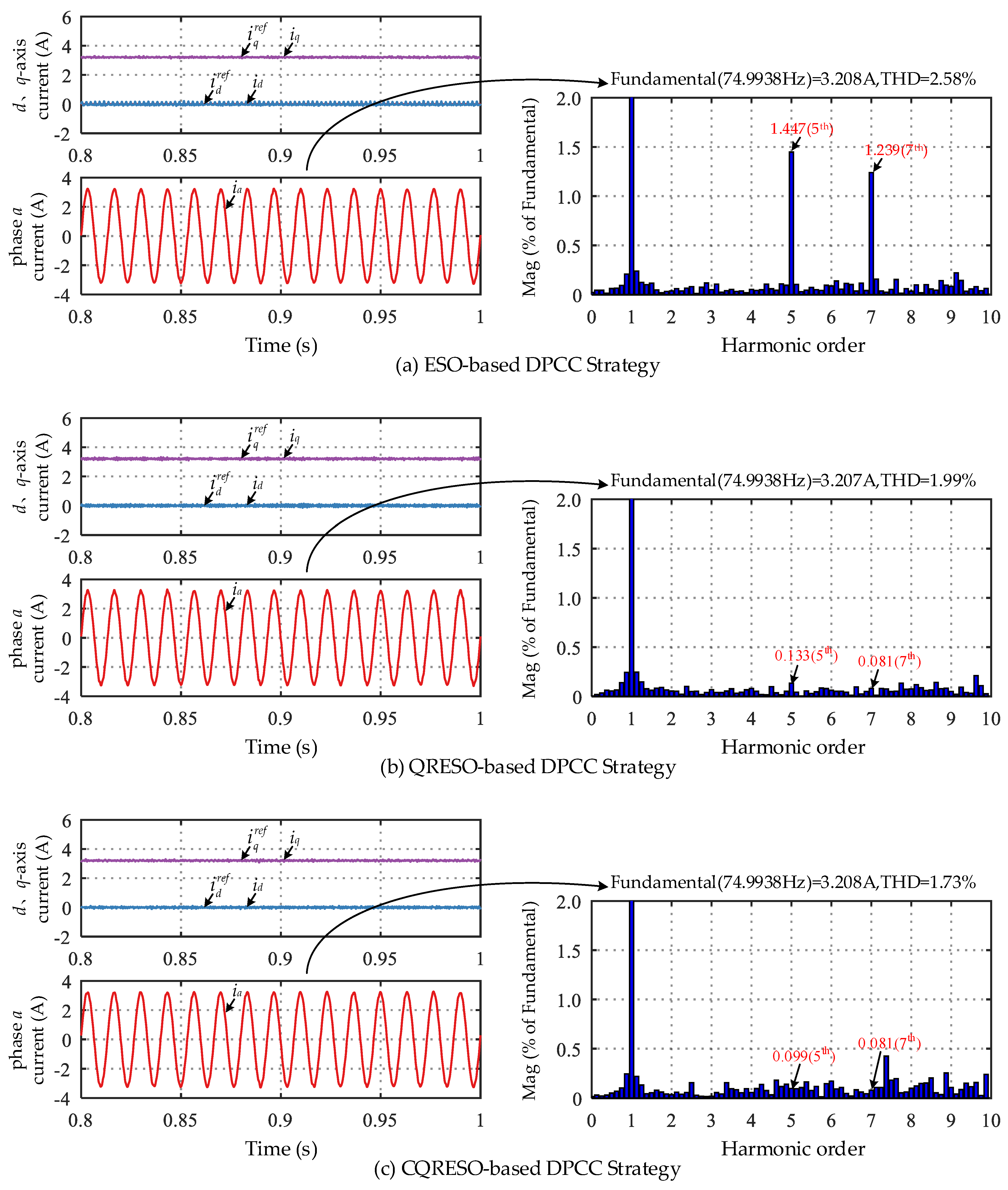
4.1. Steady-State Performance

Figure 4 shows the simulation results of the three control strategies under a load torque of 3.5 N∙m at 1500 r/min. The d-axis current id, q-axis current iq, d-axis current reference value i d r e f , q-axis current reference value i q r e f , the phase a current ia, and the fast Fourier Transform (FFT) analysis results of ia are presented in the figure. As can be seen from Figure 4, all three control strategies can enable id and iq to accurately track their reference values without steady-state errors, but different steady-state performances are exhibited. For the ESO-based DPCC strategy, the total harmonic distortion (THD) of ia is 2.58%, with noticeable 5th and 7th harmonics accounting for 1.447% and 1.239% of the fundamental component, respectively. For the QRESO-based DPCC strategy, the THD of ia decreases to 1.99%, meanwhile 5th and 7th harmonics are significantly reduced to 0.133% and 0.081% of the fundamental component, respectively. For CQRESO-based DPCC strategy, the THD of ia reaches the lowest value of 1.73%, and with further suppression of 5th and 7th harmonics to 0.099% and 0.081% of the fundamental component, respectively. The FFT analysis results of ia for the three control strategies are listed in Table 2 for ease of comparison. The simulation results demonstrate that the proposed CQRESO-based DPCC strategy can achieve good steady-state performance and exhibits superior suppression capability for 5th and 7th harmonics.

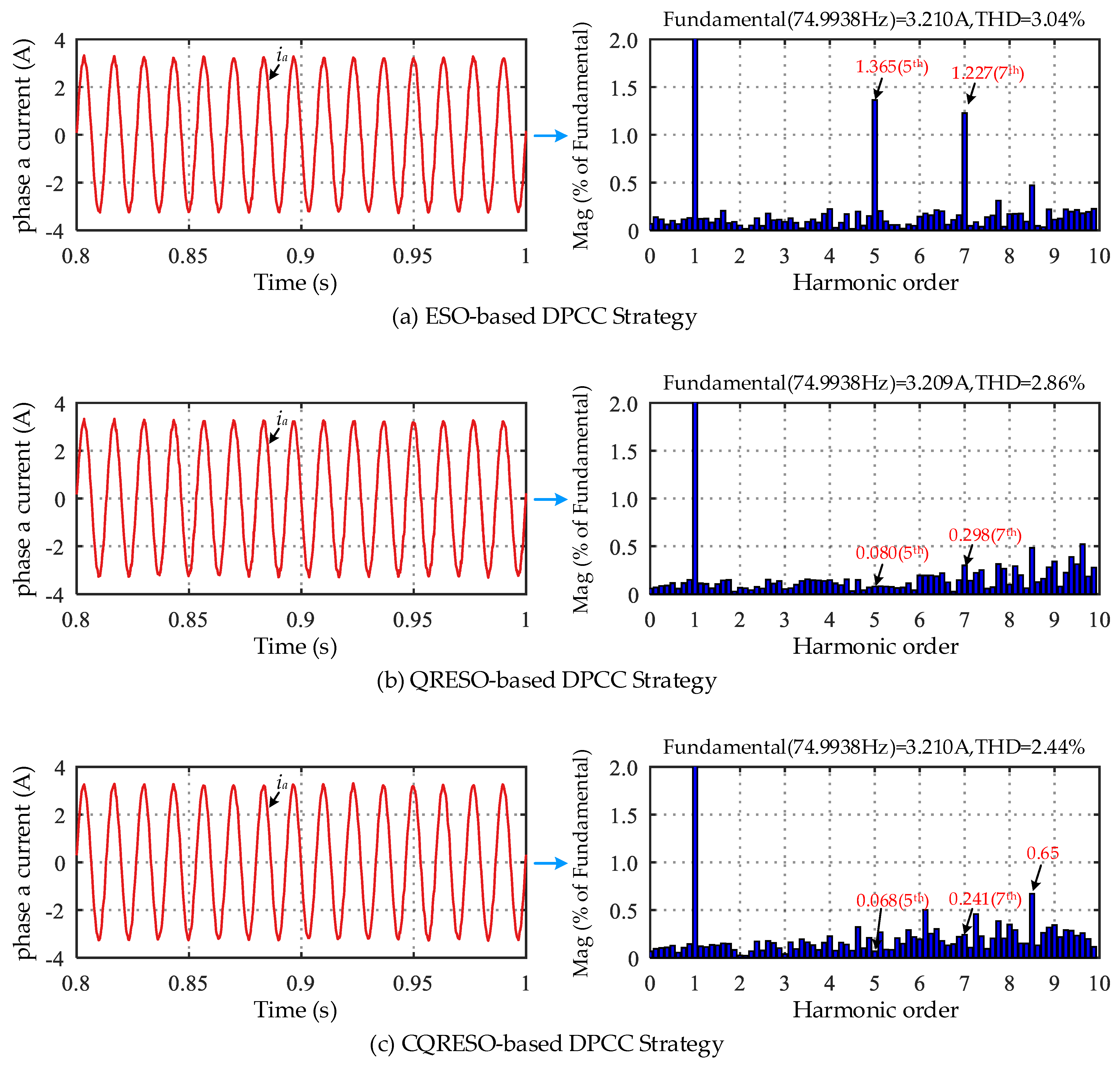
4.2. Robust Performance Comparison Under Parameter Changes

Figure 5 shows the simulation results of the three control strategies with a 3.5 N∙m load torque under a circuit mismatch at 1500 r/min. Since inductance parameter perturbation is the main disturbance affecting current loop control performance, the stator inductance Ls was selected as the test parameter here. During the test, Ls0 varies from 0.8Ls to 1.2Ls. Each subfigure presents the simulation results of the d-axis current id and q-axis current iq. As can been seen from Figure 5, with ±20% inductance parameter deviation, all three control can maintain stable system operations, enabling id and iq to accurately track their respective reference values, which exhibits good robustness.

4.3. Noise Sensitivity Performance Test

Figure 6 presents the steady-state simulation results of the three control strategies under the condition that load torque is 3.5 N∙m and with noise adding in the d- and q-axis current feedback loops at 1500 r/min. In Figure 6, the waveforms of phase a current ia and its corresponding FFT analysis results are presented. As seen, all three control strategies can maintain stable system operations, but different steady-state performances are demonstrated. For the ESO-based DPCC strategy, the THD of ia is 3.04%, with 5th and 7th harmonics accounting for 1.365% and 1.227% of the fundamental component, respectively. For the QRESO-based DPCC strategy, the THD of ia decreases to 2.86%, with 5th and 7th harmonics accounting for 0.080% and 0.298% of the fundamental component, respectively. For the CQRESO-based DPCC strategy, the THD of ia reaches the lowest value of 2.44%, with 5th and 7th harmonics accounting for 0.068% and 0.241% of the fundamental component, respectively. The FFT analysis results of ia for the three control strategies are listed in Table 3 for ease of comparison. The simulation results indicate that compared to the ESO-based and QRESO-based DPCC strategy, the proposed control strategy exhibits the least sensitivity to system measurement noise and demonstrates the best steady-state performance when considering system measurement noise.
Also, it should be noted that, as shown in Figure 4 and Figure 6, compared with the QERSO-based DPCC strategy, there are some increments in certain interharmonics when adopting the CQRESO-based DPCC strategy. Too many interharmonics will affect the system performance, such as increasing motor loss and torque fluctuations, as well as increasing vibration noise. Fortunately, the biggest value of interharmonics when adopting the CQRESO-based DPCC strategy is about 0.65%, as shown in Figure 6, which is not a big value. Since the focus of this paper is to suppress the dominant 5th and 7th current harmonics while enhancing noise rejection ability, the further improvement of performance for interharmonic suppression is not considered in this paper. But it will be the subject of our future research work in this field. For example, the CQRESO-based DPCC strategy can be combined with an optimized PWM strategy such that the interharmonics are further suppressed.

5. Conclusions

This paper takes the three-phase PMSM as a research object and proposes a CQRESO-based DPCC strategy. By introducing CQRESO to replace the mathematical model of the PMSM, the observer estimates the predicted values of d-axis and q-axis currents as well as the system total disturbance caused by deterministic and uncertain factors at the time instant k + 1. Based on this, the required control voltage command for the d-axis and q-axis system at time instant k + 1 is then calculated according to the deadbeat control principle. The comparative simulation results with ESO-based DPCC and QRESO-based DPCC strategies demonstrate that the proposed control strategy can achieve a similarly dynamic and robust performance comparable to the ESO-based DPCC and QRESO-based DPCC strategies when using a smaller observer’s bandwidth. Moreover, it exhibits superior steady-state performance and 5th and 7th current harmonic suppression capability (in the bc reference frame).

Author Contributions

Methodology, Y.L., X.Y. and Y.Z.; validation, X.Y. and T.H.; writing and editing, Y.L. and X.Y.; review, Y.Z. and T.H. All authors have read and agreed to the published version of the manuscript.

Funding

This research received no external funding.

Data Availability Statement

Data are unavailable due to privacy reasons.

Conflicts of Interest

All authors were employed by the company Chengdu Aircraft Industrial (Group) Co., Ltd. The remaining authors declare that the research was conducted in the absence of any commercial or financial relationships that could be construed as a potential conflict of interest.

References

  1. Sarlioglu, B.; T Morris, C. More electric aircraft: Review, challenges, and opportunities for commercial transport aircraft. IEEE Trans. Transp. Electrif. 2015, 1, 54–64. [Google Scholar] [CrossRef]
  2. Zhang, Z.; Xu, Y.; Yao, Y.; Yu, L.; Yan, Y. Electric power system and key technologies of more electric aircraft. J. Nanjing Univ. Aeronaut. Astronaut. 2022, 54, 969–984. [Google Scholar]
  3. Guan, L.; Lian, W. Review on electro-hydrostatic actuation technology of aircraft flight control system. Meas. Control Technol. 2022, 41, 1–11. [Google Scholar]
  4. Liu, C.; Luo, G.; Tu, W. Survey on active disturbance rejection control of permanent magnet synchronous motor for aviation electro-mechanical actuator. Meas. Control Technol. 2021, 4, 12–24. [Google Scholar]
  5. Zhang, Y.; Wang, F.; Yin, Z.; Bai, C.; Wang, G.; Liu, J. A rotor position and speed estimation method using an improved linear extended state observer for IPMSM sensorless drives. IEEE Trans. Power Electron. 2021, 36, 14062–14073. [Google Scholar] [CrossRef]
  6. Luo, G.; Zhang, R.; Chen, Z.; Tu, W.; Zhang, S.; Ralph, K. A novel nonlinear modeling method for permanent-magnet synchronous motors. IEEE Trans. Ind. Electron. 2016, 63, 6490–6498. [Google Scholar] [CrossRef]
  7. Yuang, X.; Zuo, Y.; Fan, Y.; Christopher, H.T.; Lee, C.H. Model-free predictive current control of SPMSM drives using extended state observer. IEEE Trans. Ind. Electron. 2022, 63, 6540–6550. [Google Scholar] [CrossRef]
  8. Gao, F.; Bozhko, S.; Costabeber, A.; Asher, G.; Wheeler, P. Control design and voltage stability analysis of a droop-controlled electrical power system for more electric aircraft. IEEE Trans. Ind. Electron. 2017, 64, 9271–9281. [Google Scholar] [CrossRef]
  9. Lang, X.; Yang, T.; Bai, G.; Bozhko, S.; Wheeler, P. Active disturbance rejection control of dc-bus voltages within a high-speed aircraft electric starter/generator system. IEEE Trans. Transp. Electrif. 2022, 8, 4229–4241. [Google Scholar] [CrossRef]
  10. Lang, X.; Yang, T.; Li, C.; Enalou, H.B.; Bozhko, S.; Wheeler, P. A dual-channel-enhanced power generation architecture with back-to-back converter for MEA application. IEEE Trans. Ind. Appl. 2020, 56, 3006–3019. [Google Scholar] [CrossRef]
  11. Guo, F.; Yang, T.; Bozhko, S.; Wheeler, P. Active modulation strategy for capacitor voltage balancing of three-level neutral-point-clamped converters in high-speed drives. IEEE Trans. Ind. Electron. 2022, 69, 2276–2287. [Google Scholar] [CrossRef]
  12. Cao, H.; Deng, Y.; Zuo, Y.; Li, H.; Wang, J.; Liu, X.; Lee, C.H.T. Improved adrc with a cascade extended stated observer based on quasi-generalized integrator for PMSM current disturbances attenuation. IEEE Trans. Transp. Electrif. 2024, 10, 2145–2157. [Google Scholar] [CrossRef]
  13. Zhang, Y.; Jin, J.; Huang, L. Model-free predictive current control of PMSM drives based on extended state observer using ultralocal model. IEEE Trans. Ind. Electron. 2021, 68, 993–1003. [Google Scholar] [CrossRef]
  14. Wu, S.; Shi, J.; Li, Z. Research on deadbeat predictive current control of PMSM based on ESO. Electr. Drive 2021, 51, 22–28. [Google Scholar]
  15. Ke, D.; Wang, F.; Yu, X.; Davari, S.A.; Kennel, R. Predictive error model based enhanced observer for PMSM deadbeat control systems. IEEE Trans. Ind. Electron. 2024, 71, 2242–2252. [Google Scholar] [CrossRef]
  16. Tian, M.; Wang, B.; Yu, Y.; Dong, Q.; Xu, D. Adaptive active disturbance rejection control for uncertain current ripples suppression for PMSM drives. IEEE Trans. Ind. Electron. 2023, 71, 2320–2331. [Google Scholar] [CrossRef]
  17. Chen, Z.; Zhang, X.; Liu, C.; Zhang, H.; Luo, G. Research on current decoupling and harmonic suppression strategy of permanent magnet synchronous motor based on proportional resonance type adrc. Proceeding CSEE 2022, 42, 9062–9071. [Google Scholar]
  18. Xu, J.; Wang, T.; Jia, P. Quasi-resonant active disturbance rejection control for current harmonics suppression of permanent magnet synchronous motor. Proceeding CSEE 2023, 42, 2450–2459. [Google Scholar]
  19. Yang, X.; Hu, H.; Hu, H.; Liu, Y.; He, Z. A quasi-resonant extended state observer-based predictive current control strategy for three-phase PWM rectifier. IEEE Trans. Ind. Electron. 2022, 69, 13910–13917. [Google Scholar] [CrossRef]
  20. Guo, B.; Bacha, S.; Alamir, M.; Hably, A.; Boudinet, C. Generalized integrator-extended state observer with applications to grid-connected converters in the presence of disturbances. IEEE Trans. Control. Syst. Technol. 2021, 29, 744–755. [Google Scholar] [CrossRef]
  21. Wasng, G.; Liu, R.; Zhao, N.; Ding, D.; Xu, D. Enhanced linear ADRC strategy for HF pulse voltage signal injection-based sensorless IPMSM drives. IEEE Trans. Power Electron. 2019, 34, 514–525. [Google Scholar] [CrossRef]
  22. Xie, H.; Hu, C.; Lu, M.; Liu, X.; Huang, S. Reseach on speed control strategy for permanent magnet linear synchronous motor based on cascaded linear-nonlinear active disturbance rejection controller. Proceeding CSEE 2024, 15, 6158–6168. [Google Scholar]
  23. Han, J. Active Disturbance Rejection Control Technique: The Technique for Estimating and Compensating the Uncertainties; National Defense Industry Press: Beijing, China, 2008. [Google Scholar]
  24. Hang, J. From PID to active disturbance rejection control. IEEE Trans. Ind. Electron. 2009, 56, 900–906. [Google Scholar]
  25. Gao, Z. Scaling and bandwidth parameterization based on control tuning. In Proceedings of the 2004 American Control Conference, Boston, MA, USA, 30 June–2 July 2004; pp. 4989–4996. [Google Scholar]
  26. Zhu, B. Introduction to Active Disturbance Rejection Control; Beihang University Press: Beijing, China, 2017. [Google Scholar]
Figure 1. Block diagram of CQRESO.
Electronics 14 02782 g001
Figure 2. Control block diagram of the proposed CQRESO-based DPCC strategy for the PMSM.
Electronics 14 02782 g002
Figure 3. Simulation results of the three control strategies under the condition that the current reference value suddenly changes from 0 A to 3 A.
Electronics 14 02782 g003
Figure 4. Simulation results of the three control strategies under a load torque of 3.5 N∙m at 1500 r/min.
Electronics 14 02782 g004
Figure 5. Simulation results of the three control strategies with 3.5 N∙m load torque under Ls mismatch at 1500 r/min.
Electronics 14 02782 g005
Figure 6. Simulation results of three control strategies under the condition that the load torque is 3.5 N∙m and with noise added in the d- and q-axis current feedback loops at 1500 r/min.
Electronics 14 02782 g006
Table 1. Main parameters of the PMSM.
ParameterSymbolValue
Rated speedωN1500 rpm
Stator resistanceRs02.25 Ω
D-axis inductanceLd015 mH
Q-axis inductanceLq015 mH
Number of pole pairsPn3
Rated torqueTN7 N∙m
Flux linkageψf0.249 Wb
Total inertiaJ0.0123 kg∙m2
DC side voltage of inverterUdc270 V
Table 2. FFT analysis results of ia for the three control strategies under a load torque of 3.5 N∙m at 1500 r/min.
Control StrategyTHD of ia5th Harmonic Mag (% of Fundamental)7th Harmonic Mag (% of Fundamental)
ESO-based DPCC2.58%1.4471.239
QRESO-based DPCC1.99%0.1330.081
CQRESO-based DPCC1.73%0.0990.081
Table 3. FFT analysis results of ia for the three control strategies under the condition that the load torque is 3.5 N∙m and with noise added in the d- and q-axis current feedback loops at 1500 r/min.
Control StrategyTHD of ia5th Harmonic Mag
(% of Fundamental)
7th Harmonic Mag
(% of Fundamental)
ESO-based DPCC3.04%1.3651.227
QRESO-based DPCC2.86%0.0800.298
CQRESO-based DPCC2.44%0.0680.241
Disclaimer/Publisher’s Note: The statements, opinions and data contained in all publications are solely those of the individual author(s) and contributor(s) and not of MDPI and/or the editor(s). MDPI and/or the editor(s) disclaim responsibility for any injury to people or property resulting from any ideas, methods, instructions or products referred to in the content.

