1. Introduction
In the growing field of unmanned aerial systems (UAS), precise location and touchdown capabilities are crucial, especially in applications involving payload delivery, emergency services, and disaster response. Presently, the predominant systems employed for precise landing and localization are heavily reliant on Global Navigation Satellite Systems (GNSS), frequently augmented by supplementary technologies such as visual systems, beacon guidance, or infrared navigation. Nevertheless, these methodologies encounter significant limitations in particular scenarios: GNSS signals may be compromised or interrupted in areas of high forest density, within urban canyons, or in proximity to active fire incidents, while common visual approaches, such as optical flow, are effective only at relatively low altitudes.
Furthermore, there is an increasing emphasis on the development of cooperative robotic systems that leverage the strengths of multiple specialized vehicles to accomplish complex tasks. It is often challenging to design a universal UAV, capable of addressing diverse operational needs. The implementation of collaborative systems has the potential to facilitate greater autonomy of operation and augment the system’s operational capacity. The implementation of such solutions, incorporating unmanned aerial systems (UAS) and unmanned surface vehicles, i.e., water vehicles [
1], has been shown to generate substantial improvement in effectiveness.
Although large-scale drone shows involving hundreds of UAVs do exist, their operation relies entirely on pre-computed and pre-programmed flight trajectories. Notwithstanding the establishment of communication links between drones during flight, these systems do not demonstrate autonomous decision-making capabilities. The behaviour of the group is meticulously choreographed in advance, with no real-time adaptation to dynamic environmental changes or mission objectives [
1]. Consequently, these formations cannot be classified as autonomous multi-agent systems within the context of robotics or autonomous UAV research.
In scenarios where a carrier UAV deploys smaller, task-specific payload UAVs, operators gain significant flexibility, enabling them to adapt rapidly and effectively to various mission profiles.
In order to optimize the utilization of a small aircraft, it is imperative that the landing process is executed with both safety and precision. It is evident that there exists a plethora of methodologies by which this objective may be accomplished. The utilization of laser technology, as demonstrated by LiDAR, demands a considerably elevated degree of sophistication. It is important to note that equipment utilizing different types of scanners is not immune to interference from position reception. Real-time terrain processing demands considerable computing capacity, which, in this scenario, would need to be applied directly to the aircraft. In this particular context, the utilization of edge or cloud computing is not a viable option [
2], as it is assumed that these technologies are not in place. In such circumstances, the analysis of images captured by small-scale models constitutes a complementary solution to the deployment and collaboration of two drones.
The concept of precise landing for UAS’ is well established, and a variety of solutions are currently under investigation, particularly for fixed-wing platforms. These include modifications to the flare maneuver during final approach [
3], as well as GPS-denied landing strategies [
4]. These approaches are currently being tested with a view to improving landing accuracy and robustness in environments where traditional navigation aids may be degraded or unavailable.
The impetus for this research stems from practical scenarios involving autonomous payload delivery or retrieval tasks, where the autonomous identification of suitable landing zones significantly improves mission efficiency and safety [
5]. Traditional terrain analysis or real-time environment sensing often proves overly complex and resource intensive [
6]. Conversely, the designation of landing zones through the utilization of human-defined, readily identifiable geometric patterns simplifies detection and ensures a secure landing spot. This research proposes a collaborative UAV deployment method that combines carrier-assisted localization and autonomous onboard vision-based detection [
7], significantly enhancing precision touchdown capabilities while minimizing resource consumption.
Recent studies have sought to address the challenge of performing analogous missions under resource constraints by integrating lightweight machine learning models on small UAV platforms. These models include real-time anomaly detection [
8] and low-light image enhancement guided by embedded prior maps [
9]. These approaches underscore the escalating viability of onboard autonomy in operational environments that would traditionally necessitate off-board processing.
Simultaneously, the accurate estimation of available energy and the adaptation of mission profiles remain pivotal in ensuring the proper functioning of the system. A body of research has focused on the prediction of flight time for continuous UAV missions (see, for example, [
10]). These studies provide critical insight into the integration of computational planning with energy-aware control, a subject that is of particular relevance in payload-constrained aerial systems.
Finally, as cooperative UAV missions evolve towards increasingly decentralized and multi-agent scenarios, future system extensions will benefit from formal methods developed for solving optimization problems involving multiple coordinated drones. These include exact solutions for multi-drone path planning [
11] and deployment scheduling [
12].
2. System Architecture and Methodology
This study investigates a two-stage cooperative UAV deployment system designed for precise autonomous landing in unstructured environments, but with easily marked landing targets. This chapter presents the system design, including component selection, the overall design workflow, and a detailed solution for final landing spot detection.
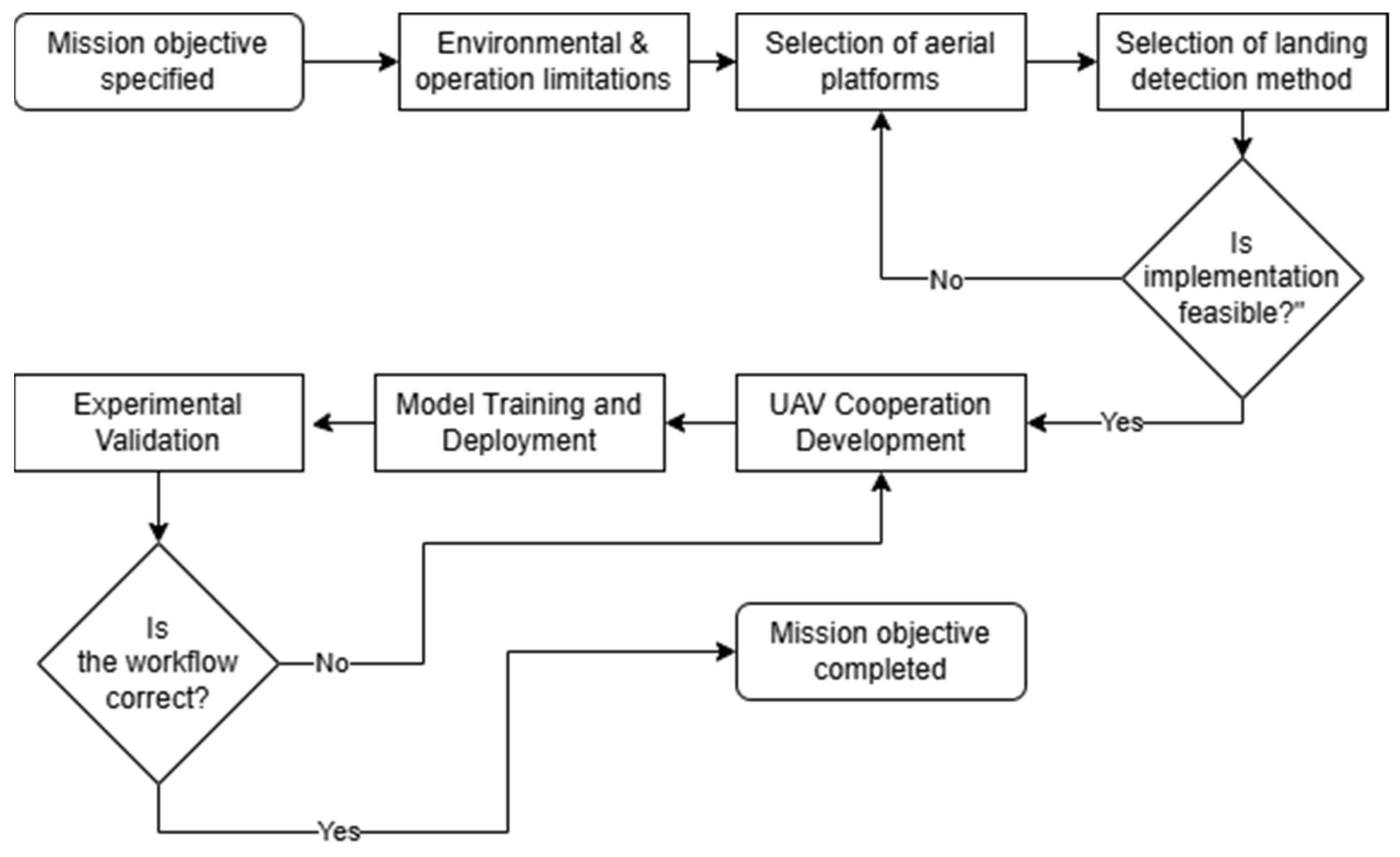
Designing such a system requires a multi-step approach [
13], as shown in
Figure 1. The entire methodology and selection process will be presented, but with emphasis on the dual location system, communication methods, and the precision-landing system for the tailsitter, without considering the issues of component manufacturing and aircraft production.
Firstly, the mission profile and operational limitations must be clearly defined. As this task was based on SAE Aerodesign competition rules for “Advanced Class” planes and adopted for delivering platform. Basic rules were introduced:
Mother ship wingspan up to 3 m,
Simple target—circle ~0.6 diameter,
Lightest possible system on detachable aircraft,
Carrier aircraft featuring onboard processing capabilities.
2.1. UAS Platforms
Platforms which are used were fully designed and manufactured in Wrocław University of Science and Technology.
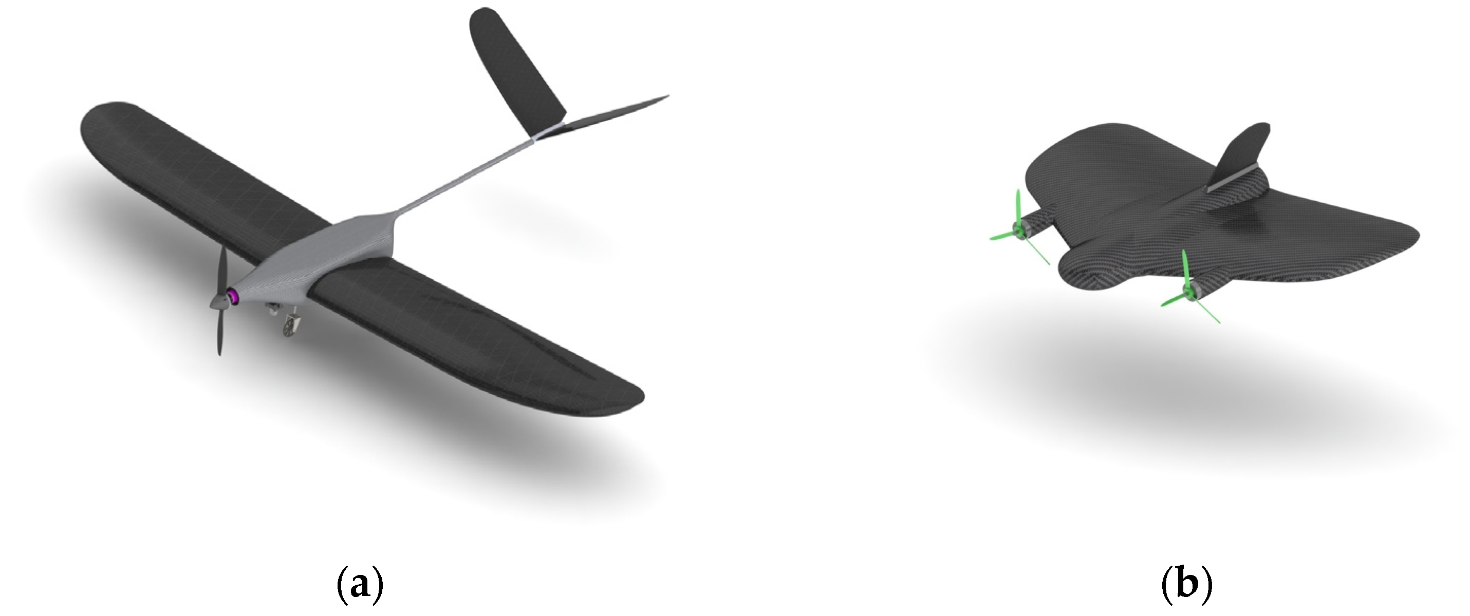
Carrier UAS (carrier aircraft—CA): a fixed-wing aircraft equipped with a high-resolution industrial grade optical camera mounted on a stabilized gimbal (
Figure 2a). It is responsible for wide-area observation, detection of landing area, and transmitting relative position data.
It is 3 m wingspan, 15 kg maximum take-off weight (MTOW) with single motor electric propulsion.
With 3 kg of payload at MTOW, it is able to fly for up to 1 h. It should be noted that mass is not the only determinant of flight time and that aerodynamic drag is also a factor in the aircraft’s performance.
Deployable UAS (payload aircraft—PA): a lightweight tailsitter UAV with conventional flying mode, hovering, and vertical takeoff and landing (VTOL) capability (
Figure 2b).
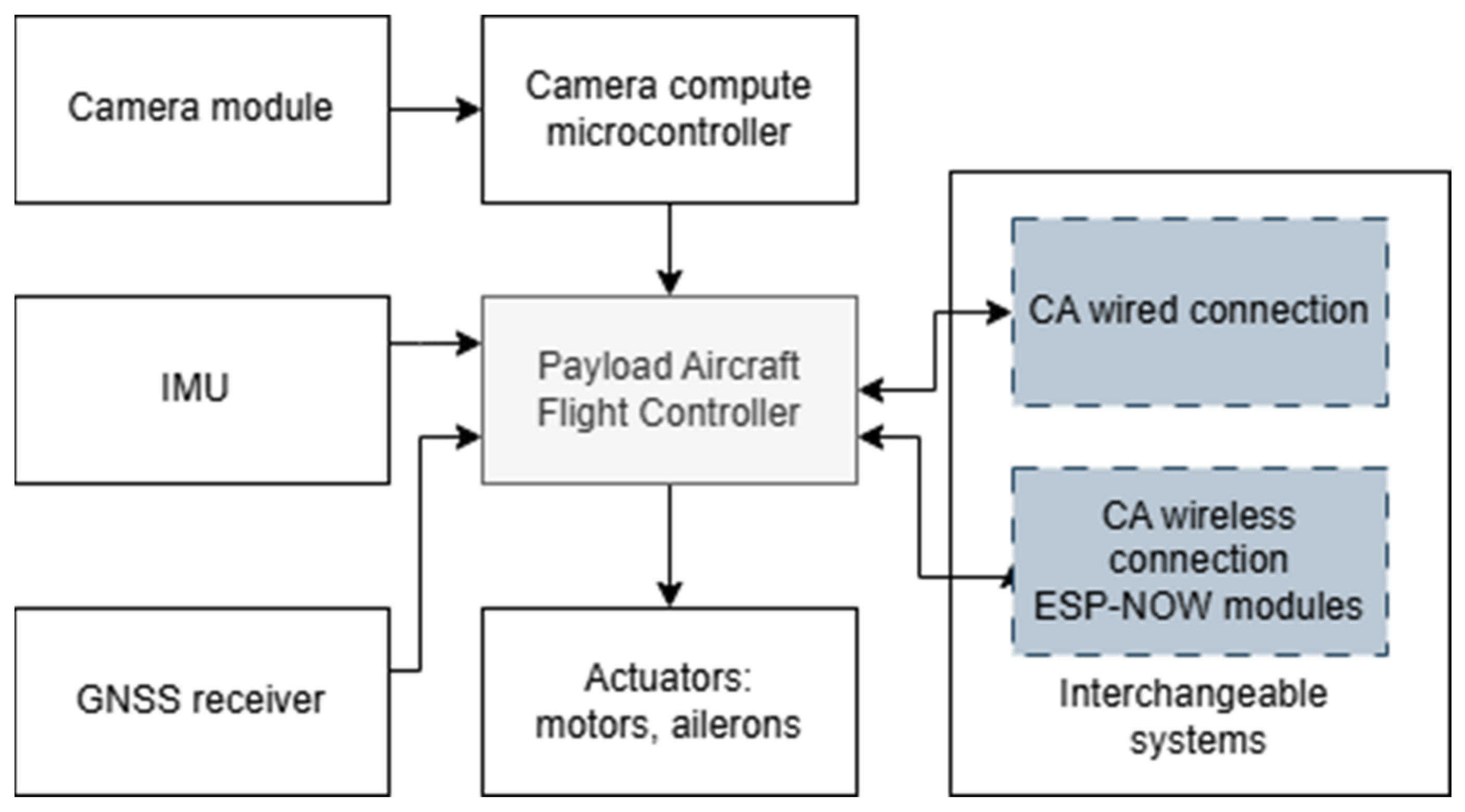
It has a weight of 0.5 kg and can carry a deliverable payload of 0.5 kg. This version demonstrates the possibility of carrying out such a mission, with the potential for scaling up in the future. It carries an onboard flight controller with wireless communication interfaces, GNSS receiver, LiDAR modules for height estimation, OpenMV H7 Plus camera module (Atlanta, GA, USA), and an embedded microcontroller for onboard inference. Both communicate with serial communication and simplified scheme for internal architecture is shown in
Figure 3.
2.2. Detection Systems
As the payload capability is a function that needs to maximize, any additional systems for PA need to be limited to minimum. A few possibilities for a detection system are available [
14] and are shown in
Table 1.
The utilization of LiDAR technology facilitates the estimation of the distance between an airborne vehicle and designated points on the ground by measuring the time-of-flight of reflected laser pulses. In order to achieve surface or full three-dimensional scanning, these systems typically employ a set of rotating mirrors. This enables a solitary beam to be employed for the comprehensive coverage of the entire surface. It is important to note that these sensors are damage-sensitive elements and carry significant weight relative to the PA which was chosen. In particular, airborne LiDAR units frequently contain mechanically delicate components, including spinning optics and alignment-sensitive elements, which are susceptible to misalignment or failure under repeated vibration, hard landings, or dust ingress—conditions commonly encountered in UAV operations. It is evident that the issue of damage sensitivity can be mitigated through the implementation of additional protective measures. Such measures may include mechanical isolation, the use of vibration-damping materials [
15], or the integration of ruggedized, military-grade equipment. However, these solutions invariably introduce additional mass, which is incompatible with the strict weight constraints imposed on the payload aircraft. The identified disadvantages preclude the selection of this solution for inclusion in the PA.
Combined systems require knowledge of the destination where the UAS will be deployed to upload map files to an offline memory on board. This also requires significant available memory on the aircraft and a powerful controller to take into account elevation data with a real-time camera feed and LiDAR point cloud [
16].
Camera-based solutions are the most flexible. These can be divided into the main categories shown in
Figure 4.
The Carrier Aircraft has the ability to power components and their available payload. This is made possible by the use of an optical system, i.e., a camera and a Jetson-type computer system, which gives the system the ability to be reconfigured and quickly adapted to new guidelines.
2.2.1. Stereo Ranging
This requires at least two cameras to point at the scene and create a 3D equivalent of reality, similarly to how human eyes work. To detect the landing zone, it correlates both pictures with knowledge about camera relative positions and computes the terrain profile [
17]. Processing two image feeds and real-time processing need a specified module. An example of a dual camera with computing unit is the ZED 2 camera (Stereo Labs, San Francisco, CA, USA). It is all contained in one unit and weighs 230 g.
2.2.2. Structure from Motion
This creates a map based on photogrammetry. It may obtain terrain information from images. Based on a single camera and low computing (as it does not have to be real time) resources, the drawback is that requires a significant amount of time to scan landing area. As shown in [
18] it may take up to 1.5 min to scan a single target.
2.2.3. Colour Segmentation
This is a method based on converting image colour information into obstacle presence. It works well with the previously checked area, in which scientists know how the grass/trees look in the given season. It may significantly differ in winter, as changes to the saved colour thresholds are required. This makes the system simple to implement, but very sensitive to changes in the environment.
2.2.4. Simultaneous Localization and Mapping
This technique is used by most advanced robots with the ability to perform autonomous flights or rides. It creates a real-time 3D map of the environment based on the camera with a fusion of other sensor data. The system utilizes a variety of algorithms for the processing of collected data and its subsequent post-processing. This capacity enables the identification of landing targets from distances as far as 20 m. However, the utilization of high-quality optics and efficient data processing is imperative, which is why unmanned aviation frequently employs edge processing as opposed to on-board processing.
2.2.5. Integrated Target Detection
This is technique for the detection of landing spots based on the specified landing target shape, which can be distinguished from the surroundings. The device utilizes a single camera, capable of operating in black and white (BW) or colour (RGB) mode. It is equipped with an integrated low-power microcontroller that facilitates the processing of images and the calculation of real-time flight corrections. The detection of the landing pad with the letter “H” was confirmed by an Italian researcher in their work [
19].
In consideration of the methodologies currently employed for the analysis and detection of landing sites, it is important to note that it is possible to land on a known or unknown landing site. It is evident that the former option is more straightforward, however, it necessitates an earlier visit to the site. Conversely, the unknown necessitates the utilization of advanced sensors and algorithms for signal processing and the discernment of necessity.
Consequently, an alternative approach was selected, integrating both options. In most cases, it is not possible to make assumptions about the terrain; however, the presence of an individual on the scene can be utilized to rapidly ascertain the safety of the environment, obviating the need for algorithms. The determined shape can then be allocated to the precise location where the aircraft should proceed. This approach facilitates a safe and precise landing, negating the need for an environmental assessment, as the suitability of the environment is already established by a person.
2.3. Onboard Computer Vision on Aircrafts
The proposed system relies on a dual-layer visual detection architecture deployed across both the carrier aircraft and PA. Each platform fulfils a complementary role in the collaborative landing process by operating at different altitudes, using distinct hardware configurations and object detection strategies tailored to their operational envelopes.
2.3.1. Carrier Vision System
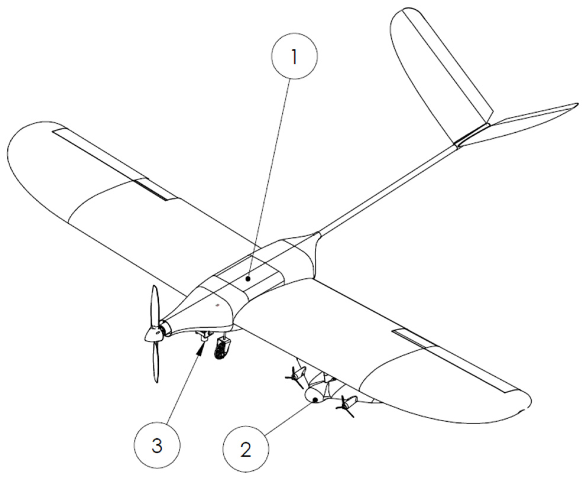
The carrier aircraft (
Figure 5, Ann. 1) is equipped with a stabilized gimbal-mounted RGB camera (
Figure 5, Ann. 3) integrated with an NVIDIA Jetson Orin Nano onboard computer. This platform executes high-resolution aerial scanning at operational altitudes of 100–200 m above ground level. A YOLOv7-based convolutional neural network was deployed for real-time object detection, specifically trained to recognize circular visual landing markers under varying environmental and lighting conditions.
The model was trained using a subset of the available dataset, augmented with additional high-altitude imagery to enhance robustness across varying perspectives. The selection of YOLOv7 was made on the basis of its favourable balance between detection accuracy and computational efficiency, particularly when deployed on compact embedded platforms. Its real-time inference capability, compatibility with constrained hardware such as the Jetson Orin Nano, and documented performance in UAV applications made it a practical choice for the high-level detection task required in the carrier aircraft.
A detailed exploration of the YOLOv7 architecture, training procedures, or comparative performance against other neural network models is beyond the scope of this work. The objective here is not to develop or benchmark algorithms of standard capabilities with small footprint computers like Jetson, but to integrate and evaluate them within a cooperative UAV deployment methodology. The gimbal system ensures image stability, enabling the model to continuously process parallel to the ground imagery during carrier flight, constantly scanning and identify candidates for landing zones.
The synchronization and handoff between the carrier and payload aircraft are executed through a staged visual detection architecture combined with a defined communication protocol. Once a valid landing marker has been detected and tracking has been stabilized over several consecutive frames (typically >1 s), a custom MAVLink message containing the relative position of the target is transmitted to the PA. This communication event serves as the trigger for both systems to synchronize their reference frames—that is to say, the actual position from GNSS, inertial or odometry systems. The subsequent step is to initiate the separation sequence. Upon release, the PA system automatically navigates to the designated relative coordinates. The acquisition of this data is contingent upon the availability of satellite signals, the precision of onboard airspeed measurements, the accuracy of wind estimation, and the performance of the inertial unit. At the designated location, the system transitions to active detection mode, utilizing its integrated OpenMV system. This system functions independently; however, it does depend on the previously determined target location for coarse localization. It is evident that the final approach phase is guided by local visual cues as opposed to global position fixes. This enables continuity in detection despite hardware and computational asymmetry between platforms. The handoff mechanism ensures both real-time responsiveness and modular autonomy, allowing each platform to operate within its optimal sensing and processing envelope. Communication between aircrafts is described in next paragraph.
2.3.2. Payload Vision System
Secondary VTOL plane is attached to the carrier in way shown in
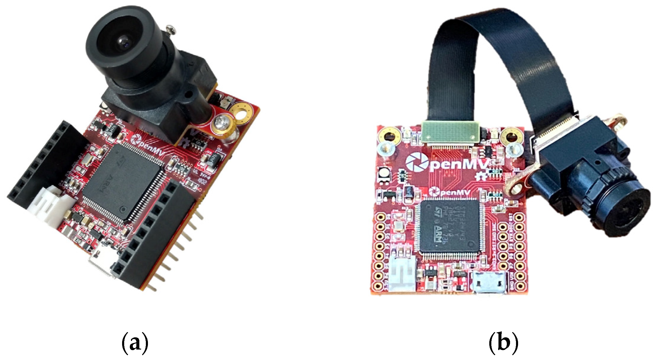
Figure 5, ann. 2. It is equipped with an OpenMV H7 Plus camera module (
Figure 6a) mounted to face downward during vertical flight mode as in
Figure 7. Due to physical limitations regarding size, it was necessary to place the printed circuit board (PCB) separately from the camera module. To address this challenge, an extension cable was employed as a solution (
Figure 6b). The OpenMV module serves as the primary onboard vision system for the final touchdown phase. This device incorporates a STM32H743 microcontroller (STMicroelectronics, Geneva, Switzerland) running at 480 MHz, 1 MB of RAM, and is equipped with an OV7725 camera sensor (OmniVision, Santa Clara, CA, USA) supporting VGA resolution (640 × 480 pixels) at up to 60 frames per second (depending on computing load).
The creation of a machine learning model was imperative in achieving autonomy during the independent flight phase and detecting a landing spot that conformed to the system’s predefined rules. To achieve real-time capabilities, a set of tests was performed to set a minimum number of corrections per second that the module must transmit to the flight controller. As demonstrated in study [
20] on Aruca type markers, a rate of two frames per second has been shown to be adequate for achieving stable landing. Conversely, the calculation of a proper position estimate in the absence of a global positioning system may necessitate the computation of as many as 50 frames per second, a task that demands the utilization of an efficient computer [
21]. Corrections to the aircraft’s actual position are prepared by the flight controller, who is responsible for the majority of position-keeping functions. It has been established that eight corrections per second are sufficient, and that Ardupilot-based flight control operates in a fully smooth and correct manner.
The learning set was prepared by conducting over 30 test flights under diverse environmental conditions. The collection of data was undertaken at a range of times during the day and in a variety of lighting conditions, with the objective of ensuring the robustness of the results. Furthermore, the dataset incorporates a wide range of terrain and background features, including variations in vegetation, soil types, and artificial surfaces, with the aim of improving generalization across real-world landing sites.
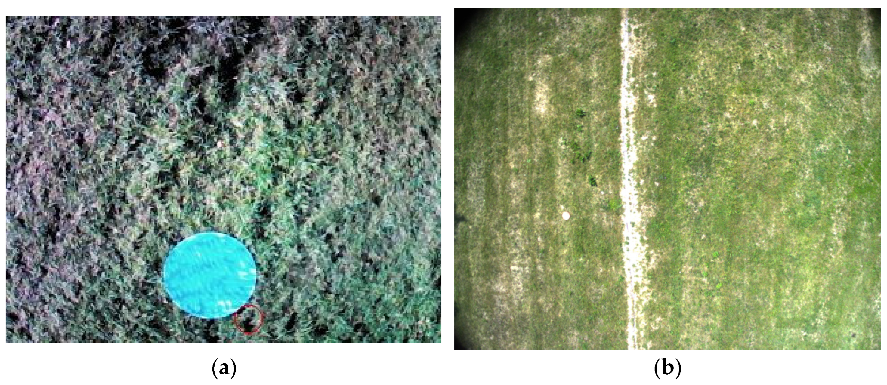
It is evident that the aerodynamic characteristics of the tailsitter configuration, notably the absence of thrust vectoring and the presence of substantial surface-area drag, result in the vehicle demonstrating significantly greater pitch angles during stationary hovering in comparison to conventional multirotor platforms. Consequently, the onboard camera frequently captures the landing marker at an oblique angle, where a nominal circle appears as an ellipse. This geometric distortion was explicitly accounted for during the construction of the dataset. The training imagery was curated to include realistic top-down and skewed perspectives of circular targets, ensuring the model’s ability to generalize across angular distortions.
Examples of unannotated training images employed in model preparation are demonstrated in
Figure 8a–d, illustrating the diversity of visual contexts and elliptical marker appearances accounted for during training.
Dataset consisted of 1221 items from which 74% was used as training set and 26% as split testing set.
In order to ensure reliable inference under constrained computational conditions, a performance analysis of the image acquisition and processing pipeline was conducted. The total latency per frame encompasses not only model inference but also the time required for image capture and memory write operations, both of which exhibit significant variation in relation to image resolution and colour mode.
It was determined through meticulous measurement that the acquisition and storage of a 100 × 100 pixel grayscale image requires approximately 50 milliseconds. For larger RGB images (e.g., 150 × 150 pixels), this delay increases to 83 milliseconds, with the aforementioned figures not including model execution time. Comparison is shown in
Table 2. When additional processing overhead is factored in, such as pixel normalization, resizing, and quantized inference, the total end-to-end latency for a single RGB frame can reach up to 150 milliseconds. This corresponds to a frame rate of fewer than seven frames per second, which falls below the desired threshold for effective real-time control.
In order to address this issue, the final implementation utilizes grayscale 100 × 100 input images. This approach has been shown to result in a significant reduction in acquisition time whilst maintaining detection accuracy. Empirical tests demonstrated no significant degradation in the precision of marker detection when using grayscale images instead of full-colour frames. It is noteworthy that although Model 3 (150 × 150 grayscale) achieved the highest F1 score at 94.0%, Model 1 (100 × 100 grayscale) offered nearly comparable accuracy (92.1%) with a significantly lower inference and acquisition latency. Consequently, the adoption of grayscale input as the default configuration was imperative to ensure a consistent processing frequency close to 9 Hz. This, in turn, facilitated the maintenance of responsive onboard control during final approach and alignment.
2.4. Communication
Robust and timely communication between CA and PA is essential to enable coordinated deployment, target handover, and autonomous mission execution. The proposed system adopts a dual-mode UART-based communication architecture, integrating wired and wireless channels in a manner contingent on the flight phase. During flight, the PA is physically attached to the CA via a rigid pylon mount (see
Figure 9, Ann. 1) and held in place by a mechanical latching mechanism with retractable locks (see Ann. 2). Electrical communication between the two airframes is facilitated by pogo-pin contacts integrated into the mounting socket (see
Figure 9, Ann. 3), thereby enabling stable wired UART data exchange without the necessity for external cabling or connectors.
The exchange of data is facilitated by the utilization of the MAVLink protocol, thereby enabling the direct transmission of structured messages between the flight controllers of the CA and PA. In addition to standard MAVLink messages (e.g., global position, attitude, system state), the system defines custom messages that signal mission-specific events such as “landing zone detected,” “separation initiated,” or “drop aborted.” Upon positive detection of a valid landing marker by the CA, the system transmits either relative or absolute coordinates to the PA (depending on configuration). This is followed by the release of the mechanical locks and execution of separation. In the event of communication failure between the UAVs due to separation or other signal degradation, the system automatically transitions to a wireless telemetry link (see
Figure 3), thereby ensuring the continuity of coordination. This fallback channel maintains MAVLink-based communication for as long as environmental conditions permit, thereby preserving situational awareness and allowing for the final confirmation of mission parameters.
The employment of a dual-channel approach is pivotal in ensuring the provision of low-latency, high-reliability communication during the critical initial phases of an operation (i.e., detection, handover, and separation). Furthermore, this approach is essential for the maintenance of sustained connectivity during the autonomous approach and landing phases of an operation.
The custom messages contain supplementary information, e.g., about the direction of wind, enabling VTOL to position itself at the correct camera side. The additional functionality of the PA, due to the absence of a PC-based unit, is realized through the use of LUA scripting. LUA scripting is a lightweight scripting language that is designed primarily for embedding in other applications.
3. Results
The developed cooperative UAV system was subjected to extensive field testing with the aim of validating its autonomous landing capability under realistic operational conditions. A series of experiments were conducted at varying altitudes, illumination levels, and environmental configurations, with the objective of simulating a number of scenarios, including forest edge clearings, rural meadows, and mixed artificial–natural terrains. The primary objective of the present study was to evaluate the end-to-end performance of the system, with a particular emphasis on the effectiveness of the collaborative architecture in locating a designated landing marker and executing a controlled descent of the payload aircraft from the carrier aircraft.
CA demonstrated robust high-altitude detection capabilities across all test environments. The YOLOv7 model was trained to recognize a circular landing marker (0.6 m diameter) and exhibited a mean average precision (mAP) of 93.6% at an Intersection-over-Union (IoU) threshold of 0.5, as determined by manually annotated aerial images. The highest levels of precision were recorded under clear lighting conditions (average precision = 96.4%), though the model demonstrated acceptable robustness under overcast skies and low sun angles (average precision = 86.2%).
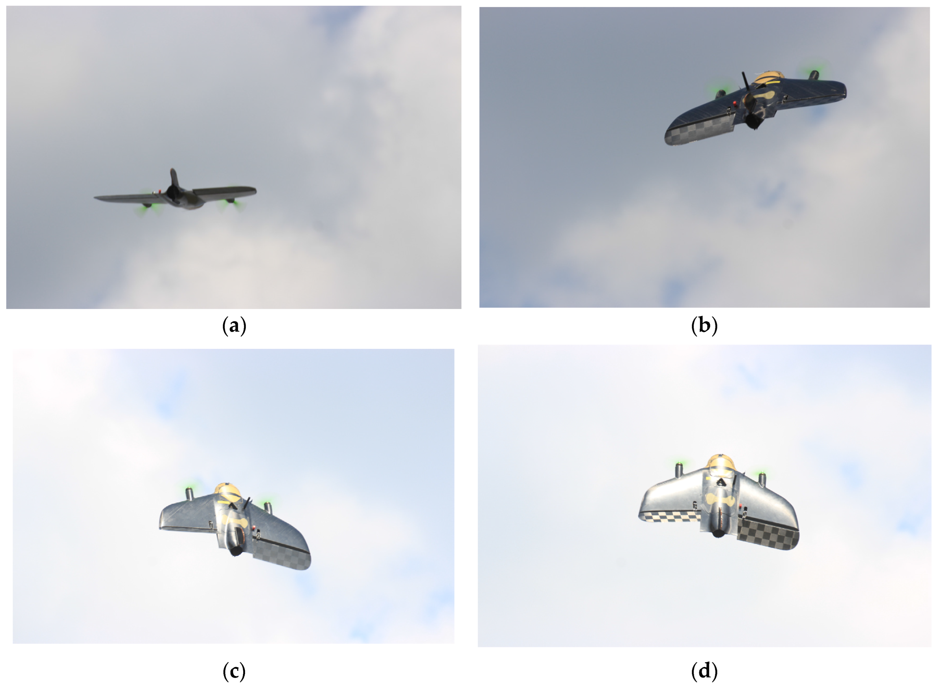
Subsequent to the detection of a valid marker, the CA was able to sustain stable tracking by means of a combination of image stabilization from the gimbal system and coordinate conversion algorithms. Following the successful localization of the marker, the system transmitted the coordinates via the MAVLink protocol to the onboard microcontroller of the PA, thereby initiating the release. In the course of a series of 20 trials designed to test the separation process shown in
Figure 10a,b, all release sequences were successfully executed. A total of 16 of these trials resulted in successful, autonomous landings, while 12 of them were completed in full vertical mode within a radius of 1.5 m from the designated marker centroid. The remaining landings exhibited a greater deviation in distance or were executed in a conventional manner, with the aircraft landing on its belly. It is imperative to acknowledge the significance of wind compensation in the final phase, particularly in light of wind gusts that have been recorded to exceed 15 m/s. This emphasizes the necessity for the utilization of wind-resistant construction methods, thereby mitigating the potential risks associated with extreme wind conditions.
Following separation, the tailsitter payload aircraft engaged its onboard guidance system. The OpenMV H7 Plus module successfully detected the circular marker in 18 out of 20 trials where the carrier detection was confirmed. The onboard network model, using 100 × 100 px grayscale inputs, achieved real-time inference rates averaging 9.3 Hz, enabling continuous heading correction during descent. False positives were not observed during controlled testing due to the high visual contrast of the designed target.
Two principal failure modes were observed. First, in one instance, intermittent backlighting and reflective surface conditions caused the OpenMV sensor to fail to reacquire the landing target after initial lock, resulting in an emergency landing in last known position. Second, during high wind episodes (>10 m/s) with additional wind gusts, tracking oscillations were noted due to momentary misalignments between onboard corrections and flight dynamics (high angle needed to keep position stable). The autonomous flight and the transit of the aircraft are shown in
Figure 11.
The results of the test flights are summarized in
Table 3. This includes the distance from the centre of the landing marker and the corresponding landing outcomes.
Two specific failure modes were identified: loss of visual target tracking due to intermittent backlighting and detection instability under strong wind gusts. These findings establish realistic boundary conditions for lightweight embedded vision systems under operational stress. The identification and documentation of these limitations constitutes an essential contribution of this work, providing concrete design guidance for future deployments, especially in energy-constrained UAVs operating in uncontrolled outdoor environments.
These exceptional scenarios do not signify systemic failure but rather highlight the circumstances under which redundancy (e.g., sensor fusion or additional environmental priors) might be required.
4. Comparative Evaluation
The present section is concerned with an evaluation, the purpose of which is to assess the feasibility of using various embedded vision computing units The analysis focuses on power consumption, real-time processing ability, and integration constraints, particularly in the context of the UAV’s energy budget and weight limitations. It also considers the trade-offs involved in selecting different classes of vision processor.
The aim is to identify configurations that offer the best balance between inference performance and operational sustainability in small-scale aerial systems by systematically quantifying energy requirements and computing capabilities.
4.1. Energy Constraints in Lightweight UAV Platforms
The PA evaluated in this study is powered by a 3S 1000 mAh lithium polymer battery, yielding an approximate total energy capacity of 11.1 Wh. Due to the demands of vertical take-off, hovering, and the final approach, most of this energy is allocated to the propulsion and flight control systems. Based on empirical observations, it is estimated that only 8–16% [
22] of the total energy budget can be allocated to the onboard vision and processing subsystem. This equates to an upper bound of around 2 Wh for missions lasting less than 10 min.
Platforms must therefore be evaluated not only for their performance in visual detection tasks, but also for their power consumption per unit time, total system mass, and thermal behaviour under load.
4.2. Performance and Power Analysis of Embedded Vision Modules
Several embedded vision modules were compared with respect to average power consumption, computational throughput, and integration feasibility in order to identify suitable computational platforms for real-time visual landing marker detection.
Table 4 summarizes the key characteristics of these platforms.
Platforms such as the Jetson Orin Nano and Google Coral offer robust deep learning capabilities and are well suited to high-altitude inference on the carrier aircraft (CA), where energy and payload constraints are less restrictive. However, they are not suitable for integration into the PA due to their high-power requirements and size. In contrast, the OpenMV H7 Plus platform strikes a compelling balance. With an average power draw of around 0.4 W and a weight of less than 20 g, it provides an embedded inference capability that fits within the PA’s energy and mass budget constraints.
4.3. Trade-Offs Between Accuracy and Autonomy
In resource-constrained UAVs, the selection of onboard vision systems inherently involves a trade-off between detection accuracy and system autonomy. High-performance platforms such as the NVIDIA Jetson Orin Nano and the Google Coral Dev Board allow advanced object detection models to be deployed with low latency and high classification accuracy. However, these platforms have high energy requirements, which reduce available flight time when used on board small electric aircraft.
To illustrate this trade-off quantitatively, we consider the integration of the Google Coral Dev Board, which consumes approximately 2.5–4 W during sustained inference. Assuming nominal consumption of 3.5 W and a target flight duration of 10 min (i.e., 1/6 of an hour), the Coral module alone would consume:
In comparison, the OpenMV H7 Plus consumes approximately 0.4 W, resulting in:
Assuming an onboard energy budget of approximately 11.1 Wh, with 80–85% allocated to propulsion and flight control (i.e., 9.3 Wh), the remaining energy available for vision and control systems is approximately 1.8 Wh. Consequently, the utilization of the Coral platform based on energy calculated in Equations (1) and (2), would consume approximately 32% of this residual budget within a mere 10 min, while the OpenMV module would consume less than 4% under identical conditions.
The results obtained from the comparison of flight time as measured in Equations (3) and (4) indicate that there is a 23% reduction in total flight time, attributable to the higher energy consumption of the Coral-based inference pipeline.
Whilst the Coral platform has been demonstrated to provide enhanced detection performance and flexibility in model selection (e. g., support for MobileNet SSD, YOLOv5 variants via TensorFlow Lite), these advantages are accompanied by a reduction in operational endurance. In the context of mission profiles where loitering or long-duration hover is imperative, such as precision landings in uncertain environments, this energy trade-off may not be deemed acceptable.
Consequently, while absolute accuracy may be superior with Coral or other higher class compute platforms. Capabilities and mission endurance achievable with low-power modules such as OpenMV remains the preferred solution for tightly constrained aerial systems.
5. Discussion
The findings from the flight trials support the operational viability of a cooperative UAV-based landing system that integrates carrier-assisted marker detection with lightweight onboard visual guidance. This hybrid approach constitutes a feasible alternative to more computationally demanding systems, such as real-time SLAM or LiDAR-based terrain reconstruction, particularly for resource-constrained platforms, including miniature VTOL tailsitters.
The 90% marker detection success rate achieved by the OpenMV-equipped payload aircraft (PA) serves to confirm the utility of compact, low-power neural inference systems in supporting autonomous descent under favourable environmental conditions. The results of the test flights are summarized in
Table 3.
In comparison with SLAM-based methods or stereo vision systems that necessitate onboard GPUs and power-consuming optical devices, the grayscale-based image classification strategy employed in this study exhibits a favourable trade-off between system complexity, payload mass, and detection reliability. However, the performance of the vision system exhibits a pronounced decline under low-illumination conditions, consistent with the observations of other researchers regarding the challenges of vision-based navigation at dusk or in shaded environments. The occurrence of emergency landing behaviour in one of the trials under scrutiny indicates the critical role of robust reacquisition protocols and potentially necessitates the incorporation of fallback visual or other safety systems based on platform type.
Moreover, the addition of inertial–visual fusion (e.g., via optical flow with IMU data) may enhance resilience in degraded visual environments, but it may be researched in future. As well as testing the system under variable terrain types and partial occlusion of the marker. Deployment of single drone may lead to the use of cooperative multi-agent swarms where one aircraft assists another’s landing by dynamically placing or confirming the safety of a landing marker.
5.1. Outlook and Future Work
The findings presented in this study provide a foundation for the conceptualization of a landing system as outlined in the text. While the present implementation successfully achieves reliable autonomous landing on known targets, several avenues for future development persist, including enhancing the system’s robustness, scalability, and autonomy.
Firstly, the localization methods may be extended to incorporate alternative positioning systems beyond visual detection and GNSS. It is possible that these could comprise visual–inertial odometry ultra-wideband or other types of night-working camera and other spectral cameras sensors. The integration of those subsystems would increase resilience to GNSS outages or harsh visual conditions.
The present dual-platform model may be expanded to accommodate multi-vehicle cooperation, thereby facilitating more intricate swarm-like missions. In this scenario, the CA would function as a central coordination unit, allocating tasks or deploying multiple PAs in succession or concurrently. The development of real-time swarm management protocols, shared situational awareness, and mutual tracking between aircrafts would be a prerequisite for this. Later research will investigate the viability of dynamic mission repartitioning, informed by onboard sensing and energy state across all aircrafts.
Preliminary work extending the current collision avoidance strategies, which are currently implemented in simplified form, is underway. The present research endeavours to explore the potential of lightweight algorithms for the purpose of facilitating inter-agent deconfliction during post-deployment descent and shared airspace operation. Integration with predictive motion models and distributed priority scheduling will be explored to achieve scalable, decentralized collision mitigation, while maintaining simplicity in hardware.
5.2. Conclusions
This study has demonstrated the feasibility and effectiveness of a low-cost approach to autonomous landing for small UAVs operating under strict energy and computational constraints. The system’s efficacy in achieving reliable precision touchdown is attributable to the employment of a hybrid cooperative architecture, incorporating vision-based detection and lightweight onboard inference. This approach obviates the necessity for complex sensors or external infrastructure, ensuring a robust and autonomous system. The findings substantiate the assertion that these methodologies signify a substantial advancement in the realm of developing resilient, extensible, and infrastructure-agnostic UAV delivery and deployment systems, particularly well-suited to resource-constrained aerial platforms.
Author Contributions
Conceptualization, A.K. and K.K.; methodology, B.D. and K.K.; software, K.K.; validation, K.K. and B.D.; formal analysis, B.D.; investigation, K.K.; resources, K.K.; data curation, K.K.; writing—original draft preparation, K.K.; writing—review and editing, B.D. and K.K.; visualization, K.K.; supervision, A.K.; project administration, A.K.; funding acquisition, K.K. and A.K. All authors have read and agreed to the published version of the manuscript.
Funding
This research was funded by Polish Ministry of Science and Higher Education: “The best of the best 4.0” Participation in a series of international competitions for UAV designers SAE Aero Design and Wrocław University of Science and Technology: Strategic Scientific Research Clubs—Academic Aviation Club of WUST.
Data Availability Statement
The raw data supporting the conclusions of this article will be made available by the corresponding authors on request.
Conflicts of Interest
The authors declare no conflicts of interest.
References
- Jan, G.E.; Lei, T.; Sun, C.-C.; You, Z.-Y.; Luo, C. On the Problems of Drone Formation and Light Shows. IEEE Trans. Consum. Electron. 2024, 70, 5259–5268. [Google Scholar] [CrossRef]
- Causa, F.; Opromolla, R.; Fasano, G. Multi-Drone Cooperation for Improved LiDAR-Based Mapping. Sensors 2024, 24, 3014. [Google Scholar] [CrossRef] [PubMed]
- Sakaki, R.; Ueba, M. Short Landing Control Techniques Using Optimization of Flare Time Constant for High-Speed Fixed-Wing UAV. Aerospace 2025, 12, 318. [Google Scholar] [CrossRef]
- Lin, Y.-X.; Lai, Y.-C. Deep Learning-Based Navigation System for Automatic Landing Approach of Fixed-Wing UAVs in GNSS-Denied Environments. Aerospace 2025, 12, 324. [Google Scholar] [CrossRef]
- Jackson, S.W.; Riccoboni, N.A.; Rahim, A.H.A.; Tobin, R.V.; Bluman, J.E.; Kopeikin, A.N.; Manjunath, P.; Prosser, E.M. Autonomous Airborne Multi-Rotor UAS Delivery System. In Proceedings of the 2020 International Conference on Unmanned Aircraft Systems (ICUAS), Athens, Greece, 1–4 September 2020; IEEE: New York, NY, USA; pp. 702–708. [Google Scholar]
- Shen, W.; Yang, Z.; Yang, C.; Li, X. A LiDAR SLAM-Assisted Fusion Positioning Method for USVs. Sensors 2023, 23, 1558. [Google Scholar] [CrossRef] [PubMed]
- Patruno, C.; Nitti, M.; Petitti, A.; Stella, E.; D’Orazio, T. A Vision-Based Approach for Unmanned Aerial Vehicle Landing. J. Intell. Robot. Syst. 2019, 95, 645–664. [Google Scholar] [CrossRef]
- Dastranj, M.; de Smet, T.; Wigdahl-Perry, C.; Chiu, K.; Bihl, T.; Boubin, J. REMIX: Real-Time Hyperspectral Anomaly Detection for Small UAVs. In Proceedings of the 2025 International Conference on Unmanned Aircraft Systems (ICUAS), Charlotte, NC, USA, 14–17 May 2025; IEEE: New York, NY, USA; pp. 60–66. [Google Scholar]
- Bai, X.; Wang, D.; Fang, J.; Li, Y.; Xu, Z. Low-Light Image Enhancement for UAVs Guided by a Light Weighted Map. Optoelectron. Lett. 2025, 21, 348–353. [Google Scholar] [CrossRef]
- Jung, S.; Jo, Y.; Kim, Y.-J. Flight Time Estimation for Continuous Surveillance Missions Using a Multirotor UAV. Energies 2019, 12, 867. [Google Scholar] [CrossRef]
- Cavani, S.; Iori, M.; Roberti, R. Exact Methods for the Traveling Salesman Problem with Multiple Drones. Transp. Res. Part. C Emerg. Technol. 2021, 130, 103280. [Google Scholar] [CrossRef]
- Deng, X.; Guan, M.; Ma, Y.; Yang, X.; Xiang, T. Vehicle-Assisted UAV Delivery Scheme Considering Energy Consumption for Instant Delivery. Sensors 2022, 22, 2045. [Google Scholar] [CrossRef] [PubMed]
- Bruni, S.; Schurr, N.; Cooke, N.; Riordan, B.; Freeman, J. Designing a Mixed-Initiative Decision-Support System for Multi-UAS Mission Planning. Proc. Hum. Factors Ergon. Soc. Annu. Meet. 2011, 55, 21–25. [Google Scholar] [CrossRef]
- Shah Alam, M.; Oluoch, J. A Survey of Safe Landing Zone Detection Techniques for Autonomous Unmanned Aerial Vehicles (UAVs). Expert. Syst. Appl. 2021, 179, 115091. [Google Scholar] [CrossRef]
- Karpenko, M.; Stosiak, M.; Deptuła, A.; Urbanowicz, K.; Nugaras, J.; Królczyk, G.; Żak, K. Performance Evaluation of Extruded Polystyrene Foam for Aerospace Engineering Applications Using Frequency Analyses. Int. J. Adv. Manuf. Technol. 2023, 126, 5515–5526. [Google Scholar] [CrossRef]
- Wang, C.; Wang, J.; Ma, Z.; Xu, M.; Qi, K.; Ji, Z.; Wei, C. Integrated Learning-Based Framework for Autonomous Quadrotor UAV Landing on a Collaborative Moving UGV. IEEE Trans. Veh. Technol. 2024, 73, 16092–16107. [Google Scholar] [CrossRef]
- Garg, R.; Yang, S.; Scherer, S. Monocular and Stereo Cues for Landing Zone Evaluation for Micro UAVs. arXiv 2018, arXiv:1812.03539. [Google Scholar] [CrossRef]
- Bi, H.; Zheng, W.; Zeng, J.; Fan, X. Modeling the Topography of Fault Zone Based on Structure from Motion Photogrammetry. In Proceedings of the 2017 IEEE International Geoscience and Remote Sensing Symposium (IGARSS), Fort Worth, TX, USA, 23–28 July 2017; IEEE: New York, NY, USA; pp. 6251–6254. [Google Scholar]
- Santoro, L.; Albanese, A.; Canova, M.; Rossa, M.; Fontanelli, D.; Brunelli, D. A Plug-and-Play TinyML-Based Vision System for Drone Automatic Landing. In Proceedings of the 2023 IEEE International Workshop on Metrology for Industry 4.0 & IoT (MetroInd4.0&IoT), Brescia, Italy, 6–8 June 2023; IEEE: New York, NY, USA; pp. 293–298. [Google Scholar]
- Chen, J.; Wang, R.; Wang, R. Vision Positioning Method for Autonomous Precise Landing of UAV Based on Square Landing Mark. J. Phys. Conf. Ser. 2020, 1651, 012182. [Google Scholar] [CrossRef]
- Kühne, J.; Magno, M.; Benini, L. Low Latency Visual Inertial Odometry with On-Sensor Accelerated Optical Flow for Resource-Constrained UAVs. IEEE Sens. J. 2025, 25, 7838–7847. [Google Scholar] [CrossRef]
- Saadi, A.A.; Bhuyan, B.P.; Ramdane-Cherif, A. Power Consumption Model for Unmanned Aerial Vehicles Using Recurrent Neural Network Techniques. Aerosp. Sci. Technol. 2025, 157, 109819. [Google Scholar] [CrossRef]
| Disclaimer/Publisher’s Note: The statements, opinions and data contained in all publications are solely those of the individual author(s) and contributor(s) and not of MDPI and/or the editor(s). MDPI and/or the editor(s) disclaim responsibility for any injury to people or property resulting from any ideas, methods, instructions or products referred to in the content. |
© 2025 by the authors. Licensee MDPI, Basel, Switzerland. This article is an open access article distributed under the terms and conditions of the Creative Commons Attribution (CC BY) license (https://creativecommons.org/licenses/by/4.0/).


