Abstract
Swarm-based unmanned aerial vehicle (UAV) systems offer enhanced spatial coverage, collaborative intelligence, and mission scalability for various applications, including environmental monitoring and emergency response. However, their onboard processing is limited by stringent size, weight, and power constraints, posing challenges for real-time computation and autonomous control. This paper presents an integrated communication and computation framework that combines cloud–edge–end collaboration with cell-free massive multiple-input multiple-output (CF-mMIMO) to enable scalable and efficient task offloading in UAV swarms. Furthermore, we implement a prototype system testbed with nine UAVs and validate the proposed framework through real-time object detection tasks. Results demonstrate over reduction in onboard computation and significant improvements in communication reliability, highlighting the framework’s potential for enabling intelligent, cooperative aerial systems.
1. Introduction
Unmanned aerial vehicles (UAVs), owing to their high mobility, flexible deployment, and cost-effective operation, have found widespread applications in a range of civil and industrial domains, including environmental monitoring, aerial photography, emergency communications, and intelligent transportation systems [1,2,3,4]. As the technological maturity of UAV platforms continues to improve, swarm-based UAV systems are gaining increasing traction due to their superior spatial coverage, multi-point collaboration, and mission scalability. These UAV swarms, typically coordinated through distributed or hierarchical control architectures, are envisioned to support complex tasks requiring real-time situational awareness and large-scale data processing. However, their onboard processing capabilities are constrained by limited size, weight, and power budgets, posing a significant challenge to the realization of intelligent, autonomous aerial operations [5]. In addition to these constraints, the ability of UAVs to withstand electromagnetic interference is increasingly recognized as a critical requirement, especially in mission-critical scenarios [6].
To address this bottleneck, computational offloading has emerged as a promising solution, allowing UAVs to offload compute-intensive tasks—such as object detection, trajectory planning, and sensor fusion—to edge servers or cloud infrastructure [7,8,9]. Existing works in this domain primarily focus on optimizing task allocation, modeling wireless communication channels, and designing adaptive scheduling strategies [10,11,12]. Approaches such as joint trajectory planning and dynamic computation partitioning have been proposed to improve overall offloading efficiency. Meanwhile, the adoption of high-capacity communication technologies, such as millimeter-wave (mmWave) and device-to-device (D2D) links, has further enhanced the feasibility of real-time task migration. However, UAV swarms operating in dynamic and dense environments still suffer from co-channel interference, intermittent connectivity, and channel fading—factors that severely degrade the quality-of-service (QoS) of computation offloading systems. In recent years, federated learning (FL) has attracted growing interest as a privacy-preserving distributed learning paradigm that enables collaborative model training across multiple UAVs or edge devices without directly sharing raw data. Integrating FL into multi-agent systems can significantly enhance the swarm’s adaptability and generalization by allowing decentralized knowledge sharing and continual learning [13,14,15,16]. Recent work has further explored latency-sensitive FL for aerial edge environments [17,18,19]. For example, the authors in [19] propose an intelligent orchestration framework for federated aerial computing that considers multi-task dependencies, heterogeneous resource demand, and the drones’ limited flight time. These ideas highlight the potential of integrating real-time FL or decentralized intelligence into UAV swarm architectures for future extension.
Against this backdrop, cell-free massive multiple-input multiple-output (CF-mMIMO) has been proposed as a promising wireless architecture to enhance spectral efficiency, coverage uniformity, and user-centric service provisioning [20,21,22,23]. Unlike conventional cellular networks, CF-mMIMO eliminates cell boundaries by deploying a large number of distributed access points (APs), all jointly coordinated by a central processing unit (CPU). CF-mMIMO is a user-centric wireless paradigm in which a large number of distributed APs jointly serve users via coherent transmission, coordinated by a CPU. Unlike cellular systems, CF-mMIMO eliminates inter-cell interference and offers consistent signal quality by avoiding hard cell boundaries. This architecture is particularly advantageous for UAV swarm networks characterized by high mobility and sparse terrestrial infrastructure, which has recently been explored for UAV communications, offering potential advantages in mitigating inter-UAV interference, enhancing link robustness, and supporting highly mobile devices in a scalable fashion. Moreover, when combined with edge/cloud computing, CF-mMIMO can facilitate ultra-reliable and low-latency task offloading in complex aerial environments [24,25,26,27,28]. Nevertheless, most existing studies remain limited to theoretical analysis or idealized simulations, with relatively few works addressing real-world deployment or experimental verification of such systems.
To the best of our knowledge, practical platforms that jointly leverage UAV swarm coordination, CF-mMIMO communication, and distributed computation frameworks (e.g., cloud–edge collaboration and FL) are still at an early stage [29,30,31]. Existing prototypes typically simplify the wireless front-end (e.g., adopting centralized Wi-Fi or LTE links) or fail to exploit the potential of distributed optimization across communication and computation domains. Furthermore, challenges such as real-time synchronization, delay compensation, and adaptive formation control in decentralized swarm environments remain largely underexplored. To address the aforementioned challenges, this paper proposes a comprehensive UAV swarm communication and computation framework that integrates cloud–edge–end collaboration with CF-mMIMO technologies. The proposed system is designed to enhance the scalability, efficiency, and reliability of computational offloading in multi-UAV scenarios. The main contributions of this paper are summarized as follows:
- We design a lightweight dynamic task migration framework that enables flexible workload allocation between onboard UAV processors and remote edge/cloud servers. This synergy significantly alleviates the processing limitations of UAVs, achieving over reduction in onboard computational load, as validated through extensive experimental evaluation.
- A CF-mMIMO-based communication architecture tailored for UAV swarms is proposed, featuring over-the-air synchronization and distributed delay compensation mechanisms. These techniques address key challenges such as remote radio unit (RRU) coordination, timing alignment, and channel state information (CSI) acquisition in dynamic and decentralized swarm environments.
- To validate the proposed architecture and computation offloading strategy, we implement a prototype system involving a swarm of nine UAVs with onboard sensing and control capabilities. The platform enables real-time object detection and offloading operations in flight, and experimental results demonstrate improved communication reliability and latency performance compared to conventional centralized baselines.
2. System Design
The proposed system architecture, depicted in Figure 1, leverages a CF-mMIMO-driven cloud–edge–terminal collaborative framework for UAV swarms. This hierarchical architecture contains three tiers:
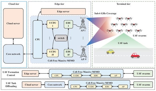
Figure 1.
System design.
- Cloud tier integrates cloud servers and core networks for centralized computation and global resource management;
- Edge tier deploys distributed CF-mMIMO transceivers with edge servers to enable spatial multiplexing and low-latency processing;
- Terminal tier comprises a swarm of K single-antenna UAVs for visual perception tasks.
In the proposed system, inter-UAV communication is indirectly achieved via cloud–edge relaying. Each UAV periodically uploads its status to the cloud server via UDP, which aggregates and broadcasts swarm-wide state updates. This design eliminates direct D2D links, simplifying synchronization and enhancing centralized coordination. To mitigate interference, the CF-mMIMO system monitors channel conditions and dynamically reallocates resources to interference-free sub-bands, ensuring link reliability during swarm operations. The hierarchical structure and functionalities of each tier are detailed below.
2.1. Cloud Tier
In this tier, the cloud server performs the following core functions: algorithmic model training, real-time inference, task scheduling, and comprehensive monitoring of resources, tasks, and network status. The algorithmic model training relies on the robust computational capabilities of cloud-based servers, where optimization is achieved through advanced artificial intelligence (AI) models or iterative algorithms [32,33,34,35]. Real-time inference leverages pre-trained models to generate predictions promptly upon receiving new data, requiring low latency and high throughput [36,37,38]. The task scheduling mechanism dynamically orchestrates resource allocation to maximize parallelism and efficiency in multi-task execution, while integrating fault-tolerant strategies to ensure resilience against potential failures [39,40]. The real-time resource monitoring system tracks resource usage to dynamically adjust allocations. The task monitoring system ensures timely handling of faults by real-time tracking of task status. The network monitoring evaluates performance in real-time to guarantee efficient and secure data transmission. Data and command exchange is facilitated between the core network and edge-tier CPUs through bidirectional interaction. These functionalities are interdependent, collectively forming a highly efficient and reliable system.
2.2. Edge Tier
The edge server centrally manages task scheduling for UAV swarms through real-time data acquisition. By leveraging the real-time status, positional data, and task priorities of all UAVs, the system optimizes task allocation to ensure efficient resource utilization. Furthermore, edge servers continuously monitor system resources, swarm task status, data traffic, and network performance metrics to dynamically optimize communication efficiency among UAV and APs. This centralized management and intelligent scheduling approach not only enhances real-time responsiveness to swarm operations but also improves the overall efficiency of task execution.
Edge servers establish reliable connectivity with UAV swarms via the CF-mMIMO architecture. The architecture ensures robust coverage in dynamic environments through large-scale deployment of APs, playing a critical role in enhancing communication reliability and reducing latency. As illustrated in Figure 1, the proposed architecture comprises N APs, M edge distributed unit (EDU), M user-centric distributed unit (UCDU), and a CPU. The APs handle radio frequency (RF) signal reception/transmission across Sub-6 GHz frequency bands, while the EDU executes distributed precoding and reception processing. The UCDU manages data distribution and combining operations.
In the considered system, it is assumed that no inter-UAV communication exists, thereby resulting in independent tasks. Furthermore, each UAV is served by N APs, where each AP is equipped with antennas. The implementation details of uplink and downlink transmissions are presented separately.
During the uplink phase, the received signal at the n-th AP is expressed as
where denotes the channel coefficient between the k-th UAV and n-th AP, represents the transmitted signal from the k-th UAV, and denotes additive white Gaussian noise (AWGN) with power at n-th AP [41].
By employing detector at the n-th AP, the transmitted signal of the k-th UAV can be collaboratively detected as
where is the indicator function that satisfies if, and only if, the k-th UAV is served by the n-th AP. In a fully distributed architecture, each AP is limited to local CSI, i.e., , and thus performs non-cooperative signal detection (e.g., conventional maximum ratio combining (MRC)). This decentralized strategy inevitably induces significant performance degradation, while full collaboration imposes prohibitive fronthaul overhead.
Following the CF-mMIMO architecture in [42], multiple APs are interconnected with a dedicated EDU for signal detection. Specifically, each user may associate with multiple EDUs but only one UCDU. After demultiplexing multi-user data streams, EDUs forward them to the associated UCDU, which performs signal aggregation from distributed EDUs. The composite partial minimum mean squared error (P-MMSE) detector at the m-th EDU is formulated as [43]
where denotes the transmit power of the k-th UAV, represents the set of UAVs associated with the m-th EDU, and denotes the equivalent channel between the i-th UAV and the m-th EDU. Substituting (3) into (2) yields the recovered uplink signal from the UAVs.
In the downlink phase, the received signal at the k-th UAV is expressed as
where denotes the precoding vector for the k-th UAV at the m-th EDU. Similarly, the downlink data stream for same UAV is exclusively transmitted from the UCDU to multiple EDUs, enabling a downlink coherent joint transmission (CJT) through coordinated beamforming across distributed EDUs [44].
2.3. Terminal Tier
Each UAV is equipped with a flight control unit (FCU), terminal processor, and communication module. The FCU acquires real-time state data including position, velocity, and attitude. The terminal processor handles mission-specific data processing, such as preliminary analysis of camera-captured video streams. Both processed results and raw data are then transmitted in real-time through the communication module to edge and cloud servers for subsequent management, analytical operations, and decision-making optimization. In this paper, we leverage the proposed cloud–edge–end architecture to offload computational tasks from UAVs to ground-based servers, thereby achieving a substantial reduction in computational energy consumption and enhanced operational endurance for UAVs. The communication terminal weighs 3 kg and measures 220 × 135 × 66 mm. It includes a Jetson Orin NX module with 25 W power consumption and 100 Tops AI inference capacity.
2.4. Interference Detection and Mitigation
To ensure robust communication under interference-prone environments, the CF-mMIMO communication layer incorporates several adaptive mechanisms.
First, the system continuously monitors the downlink transmission quality using PDCCH error statistics and ACK/NACK feedback. Based on these indicators, the baseband unit dynamically identifies affected sub-bands in the frequency domain and avoids scheduling data transmissions over heavily interfered channels.
Second, when the system detects persistent synchronization degradation in the current SSB sub-band (e.g., due to narrowband jamming), a seamless sub-band switching mechanism is triggered to reassign SSB transmission to a cleaner frequency region, maintaining synchronization reliability without physical handover.
Third, the system adopts interference-aware DCI mapping strategies. For narrowband interference, non-interleaved mapping is used to concentrate DCI transmission in clean spectrum regions. For comb-type multi-narrowband interference, interleaved mapping is employed to disperse the DCI content across available sub-band gaps, improving the probability of successful decoding.
These mechanisms collectively enhance the system’s anti-jamming capability and ensure reliable control signaling and synchronization in dynamic or hostile RF environments.
3. UAV Formation Control Technologies
UAV formation control techniques primarily include the leader–follower approach, virtual structure method, consensus-based control, artificial potential field method, and behavior-based control.
Among these, the leader–follower approach is currently the most widely adopted and mature method. It features a relatively simple control structure and is easy to implement. However, this method is highly dependent on the leader UAV, and any malfunction of the leader may result in the failure of the entire formation. To address this limitation, a virtual leader can be introduced as the overall formation reference. The position and velocity of this virtual leader are estimated and shared among UAVs in real time. This design enhances the fault tolerance of the formation and reduces its reliance on a single physical leader.
The virtual structure method conceptualizes the UAV formation as a rigid geometric configuration. During coordinated flight, each UAV maintains a fixed relative position within this virtual structure. When the formation changes its shape or trajectory, individual UAVs simply track their assigned virtual coordinates, enabling the formation to adaptively follow pre-defined inspection paths. This method ensures geometric consistency but poses challenges in large-scale implementations due to the rigidity of the structural assumptions.
The consensus-based method enables each UAV to update its state by exchanging information with neighboring UAVs, ultimately achieving global agreement on variables such as position, velocity, or heading. This approach is well-suited for distributed networks and enhances the formation’s responsiveness to dynamic environments. It also improves system robustness, as the loss or failure of a single UAV does not compromise the overall stability. However, consensus algorithms are typically complex and impose stringent requirements on communication channel capacity and latency. Prolonged communication delays or packet losses may prevent the formation from maintaining consistent states across all UAVs.
The artificial potential field method, widely used in trajectory planning, models the influence of obstacles and targets as virtual attractive and repulsive forces. While the goal exerts an attractive force on UAVs, obstacles exert repulsive forces to avoid collisions. The resultant force governs UAV motion and navigation. Although this method is simple and offers good real-time performance, it is limited in handling UAV kinematic constraints, and thus is rarely used in precise formation control tasks.
The behavior-based control method categorizes UAV responses into four fundamental behaviors: collision avoidance, obstacle avoidance, target acquisition, and formation maintenance. Each UAV determines its control actions based on weighted behavior responses to sensory inputs. Inspired by biological swarm intelligence, this method offers high flexibility and fault tolerance. However, it lacks the ability to maintain strict formation geometry and poses difficulties in mathematical stability analysis.
To ensure safe operation in large-scale UAV swarms, collision avoidance between UAVs and dynamic network reconfiguration must be considered. Among the existing formation control strategies, the leader–follower method suffers from poor anti-interference performance and single-point failure risk; the virtual structure method lacks flexibility for large-scale swarm task assignment; and the behavior-based method cannot guarantee global formation stability.
Considering these limitations, we adopt a flocking-based distributed formation control strategy. The flocking algorithm combines the advantages of consensus theory and artificial potential fields, and classifies UAVs, obstacles, and target points as -agents, -agents, and -agents, respectively. Under three key rules—separation, cohesion, and velocity alignment—UAVs can maintain a desired formation shape and move uniformly toward a target direction, while avoiding collisions and ensuring safe inter-UAV spacing. Moreover, flocking supports dynamic splitting and merging of UAV groups, offering excellent scalability and adaptability. The control rules are summarized as follows [45,46]:
- Separation: Each UAV is repelled by the sum of repulsive forces from neighboring agents to avoid collisions.
- Cohesion: Each UAV is attracted toward neighboring agents to maintain team compactness.
- Velocity alignment: Each UAV adjusts its velocity to match the average velocity of its neighbors, ensuring synchronized motion across the swarm.
Based on the aforementioned rules, considering the realistic swarm flight environment, the flocking algorithm adopted in this work is designed as follows.
3.1. Separation
For local repulsive forces, a simple semi-spring model is employed, using a linearly distance-dependent central velocity term. Interaction begins only within a maximum range , beyond which repulsion is ignored.
where is the linear gain of the repulsive force, and denote the coordinate vectors of agent i and j in the global coordinate system, respectively, and is the distance between agent i and j. The total repulsive force on agent i from all neighbors is
3.2. Velocity Alignment
Velocity alignment is achieved by introducing a velocity term based on the difference in velocity vectors among nearby agents. The objective is to synchronize motions and reduce self-induced oscillations due to delays or noise. A smooth velocity decay function, , based on an ideal braking curve is adopted, with constant acceleration at high speed and exponential convergence at low speed.
where r is the distance to the target stopping point, a is the preferred acceleration, and p is a linear gain that determines the crossover between two deceleration phases.
The fundamental principle of the velocity alignment term is to constrain the velocity difference between any two agents such that it does not exceed the maximum allowed by the ideal braking curve at a given distance. As such, this alignment mechanism can be treated as a motion planning term within the force-based motion model
where , denotes the linear coefficient for reducing velocity alignment error, is the velocity relaxation term that allows a certain degree of velocity difference to exist independently of the inter-agent distance. The variable refers to the distance between agent i and the predicted stopping point ahead of agent j. Parameters and represent the pairwise linear gain and acceleration parameters, respectively. The amplitude of the speed difference between agent i and j is denoted by . The total velocity alignment term for agent i with respect to all other agents is given by
In addition, the locality condition of the velocity alignment mechanism is implicitly ensured by defining a maximum interaction range . On the other hand, this formulation allows for flexible scalability in the velocity domain. Specifically, for swarms operating at higher speeds, it is beneficial to begin reducing velocity differences at larger distances to prevent potential collisions and improve formation coherence.
3.3. Collision Avoidance and Obstacle Avoidance
Long-range attraction is not an explicit part of this flocking system. To keep the agents together, a bounded flying arena is defined for the agents, surrounded by soft-repelling virtual walls. One ideal way to define such a repulsion is to define virtual “shield” agents near the arena walls. These virtual agents are rushing towards the arena at a certain velocity. Real agents near the walls should relax their velocities to the velocity of the virtual agents. The velocity alignment term for the virtual agent i is
where is the distance between the virtual agent i and s. Parameter , where is the speed of the virtual agent, perpendicular to the edge of the wall polygon pointing inwards towards the arena, is the reference distance, and is the base virtual agent speed. is the dynamic speed coefficient. For each wall or obstacle, multiple virtual agents can be defined, located at different distances to enhance obstacle avoidance. The same concept can be used to avoid convex obstacles within the arena, but with agents moving outward from the obstacle, rather than inward, as described above for the arena. Another difference is that while all wall polygon edges spawn a separate virtual agent within the arena, obstacles are represented with a single virtual agent located at the closest point of the obstacle polygon relative to the agent. Therefore, for each agent, a velocity component can be defined similarly to , using the same parameters as for the walls.
3.4. Self-Driving
The self-driving term represents the agent’s desired velocity, which aligns with its actual motion direction. To improve adaptability, dynamic self-driving terms can be introduced, including speed adaptation and directional correction.
(1) Speed Adaptation
The actual speed of the swarm , which refers to the final movement speed of the entire swarm of unmanned aerial vehicles under collaborative action, is defined as
where is the basic self-driving speed, is the speed adaptation coefficient, is the speed vector of agent i, and denotes the maximum system speed.
(2) Directional Correction
The final target speed vector of agent i is represented as
where is the direction correction, which adjusts the movement direction of the agent i.
3.5. Final Desired Velocity
The final desired velocity is computed as the vector sum of all interaction forces:
(1) Dynamic Speed Limits
The current maximum speed , which is the maximum speed value that an agent can achieve under specific conditions, is defined as
where is the initial maximum speed, is the adjustment coefficient, is the current swarm size, and is the maximum group size.
(2) Directional Correction
The final target speed vector of agent i is the same as Equation (13).
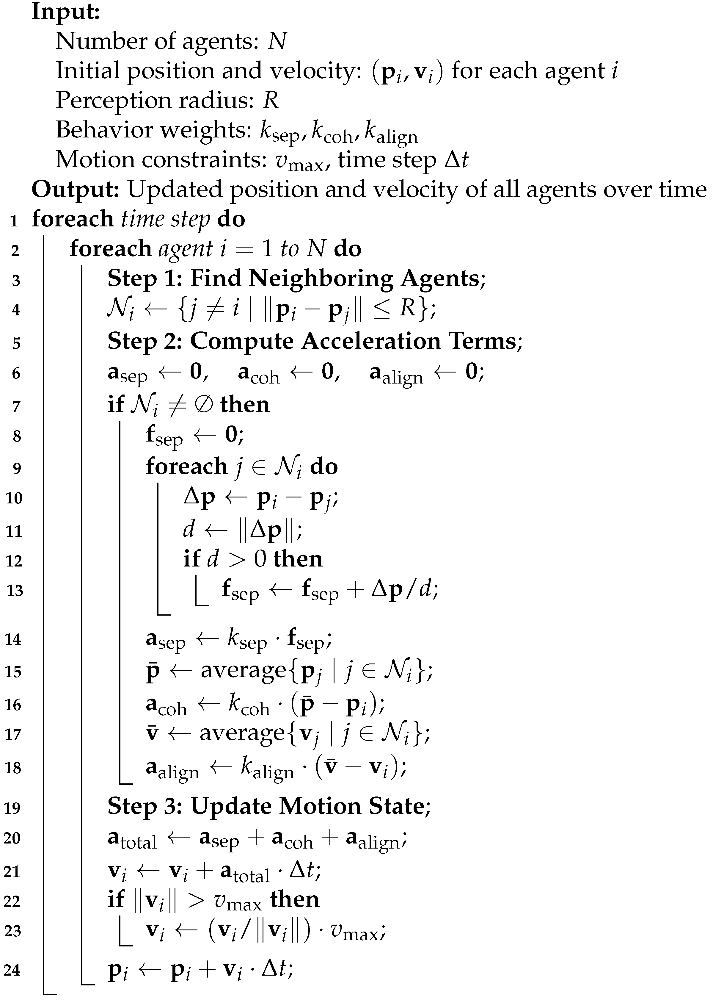
3.6. Solution Based on Flocking Control Algorithm
The algorithm uses three rules, separation, aggregation, and speed alignment, to ensure that the drone group maintains a fixed distance and constant speed during flight, avoids collisions, and achieves the separation and reorganization of any individual. Compared with traditional centralized or distributed formation control methods, the Flocking algorithm shown in Algorithm 1 has better flexibility and robustness, can adapt to complex environmental changes, and improves the coordination ability and task execution efficiency of the drone swarm.
| Algorithm 1: Flocking-based swarm motion control. |
 |
4. Experimental Validation
To validate the proposed CF-mMIMO-based UAV swarm communication and computation framework, we developed a hardware prototype system comprising a cloud–edge collaborative computing platform and a UAV terminal layer, as shown in Figure 2 and Figure 3, respectively. This platform supports real-time task migration, low-latency data exchange, and distributed control in dynamic swarm scenarios.
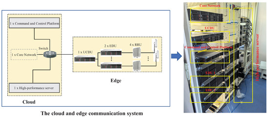
Figure 2.
Cloud and edge communication platform.
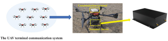
Figure 3.
UAV platform.
4.1. System Architecture Overview
The cloud system in Figure 2 includes a centralized command and control unit, a core network, and a high-performance computing server. It handles model training, real-time inference, task scheduling, and secure bidirectional data exchange. A resource orchestration framework ensures dynamic workload allocation, parallel task execution, and fault tolerance. Modules for resource monitoring, task tracking, data management, and network status evaluation are integrated to support scalable and resilient operation.
The edge system in Figure 2 includes one UCDU, two EDUs, and four RRUs, interconnected with the cloud via fiber-optic links. The UCDU performs modulation/demodulation and handles channel encoding/decoding. The EDUs allocate baseband processing resources dynamically according to traffic load, while the RRUs upconvert baseband signals to RF for long-range CF-mMIMO transmission to UAVs. The edge layer also manages mission scheduling based on UAV status and supports real-time coordination.
The UAV system in Figure 3 consists of nine quadrotors equipped with onboard FCUs, gimbal-mounted cameras, and edge computing modules. The FCU provides real-time state information including position, velocity, and orientation. The gimbal captures live video streams for visual perception. Onboard processors handle lightweight inference or feature extraction and transmit both raw and processed data to the edge/cloud servers. This architecture supports autonomous operation and efficient task execution in dynamic environments.
4.2. Experimental Setup
Each UAV platform has a 1400 mm wheelbase, 15 kg payload capacity, and a full-load flight endurance of 35 min. The onboard Jetson Orin NX (NVIDIA, Santa Clara, CA, USA) module contains 1024 CUDA cores, 64 Tensor cores, and a 6-core Carmel ARM CPU, supporting 100 Tops AI inference.
The cloud server is a Y9000P laptop equipped with an Intel Core i9-13900HX processor (Intel, Santa Clara, CA, USA), NVIDIA RTX 4080 Ti GPU (NVIDIA, Santa Clara, CA, USA), 32 GB DDR5 memory, and a 1 TB SSD. The CF-mMIMO base station operates in the 3.7–3.8 GHz band and is deployed at a 15 m elevation. UAV field trials are conducted 28.44 km from the base station, with UAVs hovering at 5 m altitude and 8 m horizontal spacing.
The CPU/GPU usage on UAVs is monitored via jtop. The GPU usage of cloud and edge servers is tracked using nvidia-smi, and CPU load is measured by aggregating inference thread utilization using top.
4.3. Practical Deployment Considerations
In real-world deployment, several practical challenges is addressed. First, environmental constraints such as beam coverage limitations and Earth curvature effects over long-range links necessitate careful placement of CF-mMIMO base stations. In our field validation in Figure 4, we successfully conducted UAV offloading tests at a distance of 28.44 km from the edge communication station, demonstrating the feasibility of long-range connectivity. Second, the proposed CF-mMIMO system exhibits high scalability, benefiting from large bandwidth and distributed processing. As shown in Figure 4, our hardware testbed successfully supported real-time flight of all nine drones, confirming that the system architecture meets the requirements of large-scale cluster access. Third, in terms of fault tolerance and interference resilience, the cell-free architecture ensures operational continuity even if one or more EDUs are disabled, as each EDU handles local detection and precoding independently. For PDSCH/PDCCH transmission, the system utilizes ACK/NACK feedback to estimate sub-band-level error rates, enabling dynamic avoidance of interfered sub-bands, adaptive modulation and coding scheme (MCS) adjustments, and interleaving. Synchronization robustness is maintained through real-time SSB monitoring; upon detecting loss of sync, the system dynamically switches the synchronization frequency to ensure link continuity.
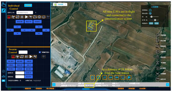
Figure 4.
Ground command and control platform for UAV flight testing.
These practical enhancements demonstrate that the proposed CF-mMIMO-enabled offloading framework is not only technically effective but also resilient and scalable in real-world UAV swarm deployments.
4.4. Experimental Results
For comparison, we evaluate the system performance under two configurations: (i) all object detection is executed locally on UAVs without offloading; and (ii) computation tasks are dynamically offloaded to the cloud using the proposed framework. Figure 5 shows the CPU and GPU usage of the cloud and edge servers, Figure 6 presents the CPU usage on different UAVs, and Figure 7 illustrates their GPU usage. The decrease in GPU utilization results from transferring the YOLOv5 inference to the cloud. Meanwhile, the slight increase in CPU usage is attributed to communication overhead, data formatting, and control signaling required for offloading and feedback coordination.
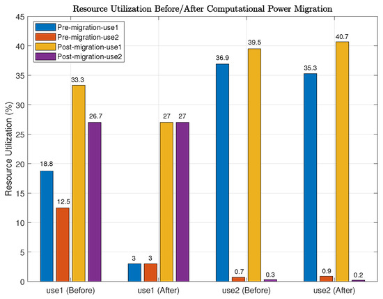
Figure 5.
Comparison of CPU and GPU utilization on the cloud and edge servers before and after computation offloading.
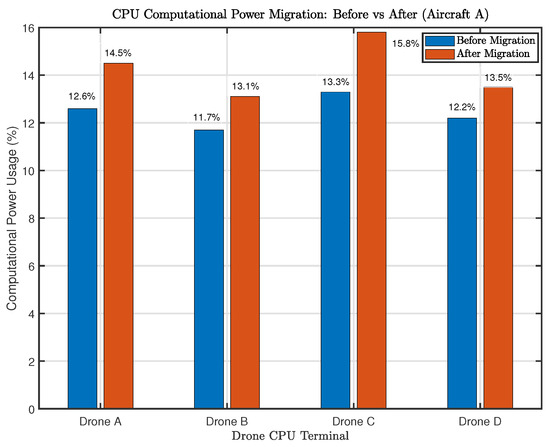
Figure 6.
CPU utilization comparison of different UAVs before and after computation offloading.
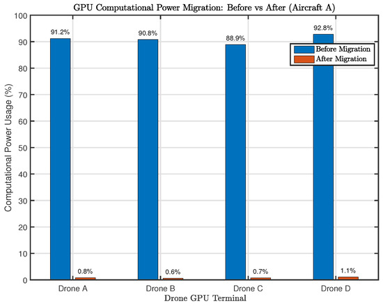
Figure 7.
GPU utilization comparison of different UAVs before and after computation offloading.
According to the measurements, the cloud server’s CPU utilization increased from and to and , respectively, while its GPU usage rose from to . The edge server’s task-related CPU usage slightly increased from to . For the UAVs:
- Drone A: CPU increased from to , GPU dropped from to ;
- Drone B: CPU increased from to , GPU dropped from to ;
- Drone C: CPU increased from to , GPU dropped from to ;
- Drone D: CPU increased from to , GPU dropped from to .
The detection accuracy was quantified using IoU consistency in bounding box outputs. These flight experiments validate the effectiveness of the proposed cloud–edge–end computational orchestration framework and the distributed formation control mechanism. The results demonstrate that after task migration, the target detection algorithm continues to operate correctly. The significant increase in cloud GPU usage and the corresponding reduction in onboard GPU load, without compromising detection accuracy or display latency, confirm the efficiency and reliability of the proposed system.
To analyze latency savings, we measured both communication and computation delays, as shown in Figure 8.
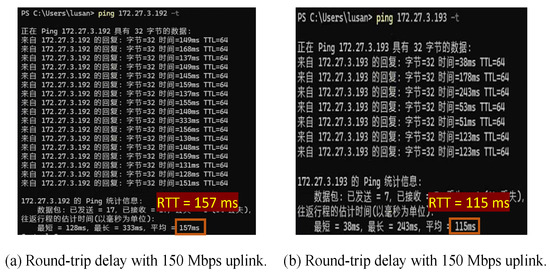
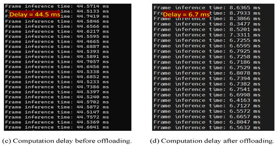
Figure 8.
Latency breakdown under different conditions: (a,b) show end-to-end round-trip time (RTT) under different uplink rates; (c,d) show computation delay before and after offloading.
- Communication latency: After each UAV terminal completed network access, we used iperf to generate uplink traffic and standard ping to measure round-trip time (RTT). With a 100 Mbps uplink rate, the average RTT was 115 ms; increasing the rate to 150 Mbps led to a slightly higher RTT of 157 ms due to increased queuing and resource contention.
- Computation latency: Using the YOLOv5 model on the UAV’s onboard module resulted in an average inference delay of 44.5 ms, due to constrained processing. After offloading the task to the cloud/edge platform, the inference delay dropped to 6.7 ms, achieving a notable latency reduction while maintaining detection accuracy.
These results confirm that the proposed offloading framework improves system responsiveness by significantly reducing both computation and transmission delay components.
5. Conclusions
This paper presented an integrated communication and computation framework for UAV swarms, combining cloud–edge–end collaboration with a CF-mMIMO architecture. A robust CF-mMIMO protocol with synchronization and delay compensation was implemented to ensure reliable wireless connectivity in dynamic swarm environments. The proposed system achieved a reduction in onboard computation while maintaining detection accuracy after migration. Experiments demonstrated that the proposed system significantly improves computational efficiency, communication reliability, and end-to-end latency.
While this study validates the feasibility of CF-mMIMO-based offloading for UAV swarms, future work will focus on scaling to larger swarm sizes via decentralized coordination and adaptive task partitioning. Integrating technologies such as reconfigurable intelligent surfaces (RIS) and non-terrestrial networks (NTNs) may further enhance communication robustness [47]. In addition, AI-driven control using federated or reinforcement learning could enable more autonomous, adaptive behavior. These directions also raise new challenges in latency control, convergence, and reliability under resource constraints. Furthermore, hardware-level enhancements—such as terminal miniaturization, aerodynamic integration, and systematic EMI shielding—will be pursued to reduce onboard load and improve real-world deployability in complex electromagnetic environments.
Author Contributions
J.S. was the main author. H.L., W.S. and D.W. provided the methodology, software, and constructive feedback on every part of this manuscript. W.X. was our supervisor. All authors have read and agreed to the published version of the manuscript.
Funding
This work was supported in part by the National Key Research and Development Program under Grant 2020YFB1806608, and in part by the Special Fund for Key Basic Research in Jiangsu Province No. BK20243015.
Data Availability Statement
The datasets generated and analyzed during the current study are not publicly available due to institutional policy and hardware privacy constraints. Requests to access the data can be directed to the first author at jiansun@seu.edu.cn.
Conflicts of Interest
The authors declare no conflicts of interest.
References
- You, X.H.; Wang, C.X.; Huang, J.; Gao, X.Q.; Zhang, Z.C.; Wang, M.; Huang, Y.M.; Zhang, C.; Jiang, Y.X.; Wang, J.H.; et al. Towards 6G wireless communication networks: Vision, enabling technologies, and new paradigm shifts. Sci. China Inf. Sci. 2020, 64, 1–74. [Google Scholar] [CrossRef]
- Xu, W.; Yang, Z.; Ng, D.W.K.; Levorato, M.; Eldar, Y.C.; Debbah, M. Edge learning for B5G networks with distributed signal processing: Semantic communication, edge computing, and wireless sensing. IEEE J. Sel. Top. Signal Process. 2023, 17, 9–39. [Google Scholar] [CrossRef]
- Li, B.; Fei, Z.; Zhang, Y. UAV communications for 5G and beyond: Recent advances and future trends. IEEE Internet Things J. 2019, 6, 2241–2263. [Google Scholar] [CrossRef]
- Shi, W.; Xu, W.; You, X.H.; Zhao, C.M.; Wei, K.J. Intelligent reflection enabling technologies for integrated and green Internet-of-Everything beyond 5G: Communication, sensing, and security. IEEE Wirel. Commun. 2023, 30, 147–154. [Google Scholar] [CrossRef]
- Mozaffari, M.; Saad, W.; Bennis, M.; Nam, Y.H.; Debbah, M. A tutorial on UAVs for wireless networks: Applications, challenges, and open problems. IEEE Commun. Surv. Tuts. 2019, 21, 2334–2360. [Google Scholar] [CrossRef]
- Jie, H.; Zhao, Z.; Zeng, Y.; Chang, Y.; Fan, F.; Wang, C.; See, K.Y. A review of intentional electromagnetic interference in power electronics: Conducted and radiated susceptibility. IET Power Electron. 2024, 17, 1487–1506. [Google Scholar] [CrossRef]
- Hu, Q.; Cai, Y.; Yu, G.; Qin, Z.; Zhao, M.; Li, G.Y. Joint offloading and trajectory design for UAV-enabled mobile edge computing systems. IEEE Internet Things J. 2019, 6, 1879–1892. [Google Scholar] [CrossRef]
- Yu, Z.; Gong, Y.; Gong, S.; Guo, Y. Joint task offloading and resource allocation in UAV-enabled mobile edge computing. IEEE Internet Things J. 2020, 7, 3147–3159. [Google Scholar] [CrossRef]
- Li, M.; Cheng, N.; Gao, J.; Wang, Y.; Zhao, L.; Shen, X. Energy-efficient UAV-assisted mobile edge computing: Resource allocation and trajectory optimization. IEEE Trans. Veh. Technol. 2020, 69, 3424–3438. [Google Scholar] [CrossRef]
- Hu, X.; Wong, K.; Yang, K.; Zheng, Z. UAV-assisted relaying and edge computing: Scheduling and trajectory optimization. IEEE Trans. Wirel. Commun. 2019, 18, 4738–4752. [Google Scholar] [CrossRef]
- Yang, L.; Yao, H.; Wang, J.; Jiang, C.X.; Benslimane, A.; Liu, Y. Multi-UAV-enabled load-balance mobile-edge computing for IoT networks. IEEE Internet Things J. 2020, 7, 6898–6908. [Google Scholar] [CrossRef]
- Zhao, N.; Ye, Z.; Pei, Y.; Liang, Y.C.; Niyato, D. Multi-agent deep reinforcement learning for task offloading in UAV-assisted mobile edge computing. IEEE Trans. Wirel. Commun. 2022, 21, 6949–6960. [Google Scholar] [CrossRef]
- Yang, H.; Zhao, J.; Xiong, Z.; Lam, K.Y.; Sun, S.; Xiao, L. Privacy-preserving federated learning for UAV-enabled networks: Learning-based joint scheduling and resource management. IEEE J. Sel. Areas Commun. 2021, 39, 3144–3159. [Google Scholar] [CrossRef]
- Shi, W.; Yao, J.C.; Xu, W.; Xu, J.D.; You, X.H.; Eldar, Y.C.; Zhao, C.M. Combating interference for over-the-air federated learning: A statistical approach via RIS. IEEE Trans. Signal Process. 2025, 73, 936–953. [Google Scholar] [CrossRef]
- Yao, J.C.; Shi, W.; Xu, W.; Yang, Z.; Swindlehurst, A.L.; Niyato, D. Byzantine-resilient over-the-air federated learning under zero-trust architecture. IEEE J. Sel. Areas Commun. 2025, 43, 1954–1969. [Google Scholar] [CrossRef]
- Shi, W.; Yao, J.C.; Xu, J.D.; Xu, W.; Xu, L.; Zhao, C.M. Empowering over-the-air personalized federated learning via RIS. Sci. China Inf. Sci. 2024, 67, 219302. [Google Scholar] [CrossRef]
- He, W.; Yao, H.; Mai, T.; Wang, F.; Guizani, M. Three-stage stackelberg game enabled clustered federated learning in heterogeneous UAV swarms. IEEE Trans. Veh. Technol. 2023, 72, 9366–9380. [Google Scholar] [CrossRef]
- Wang, P.; Yang, H.; Han, G.; Yu, R.; Yang, L.; Sun, G.; Qi, H.; Wei, X.; Zhang, Q. Decentralized navigation with heterogeneous federated reinforcement learning for UAV-enabled mobile edge computing. IEEE Trans. Mob. Commun. 2024, 23, 13621–13638. [Google Scholar] [CrossRef]
- Awada, U.; Zhang, J.; Chen, S.; Li, S. AirEdge: A dependency-aware multi-task orchestration in federated aerial computing. IEEE Trans. Veh. Technol. 2022, 71, 805–819. [Google Scholar] [CrossRef]
- Ngo, H.Q.; Ashikhmin, A.; Yang, H.; Larsson, E.G.; Marzetta, T.L. Cell-free massive MIMO versus small cells. IEEE Trans. Wirel. Commun. 2017, 16, 1834–1850. [Google Scholar] [CrossRef]
- Cao, Y.; Wang, P.; Zheng, K.; Liang, X.H.; Liu, D.; Lou, M.; Jin, J.; Wang, Q.; Wang, D.; Huang, Y.M.; et al. Experimental performance evaluation of cell-free massive MIMO systems using COTS RRU with OTA reciprocity calibration and phase synchronization. IEEE J. Sel. Areas Commun. 2023, 41, 1620–1634. [Google Scholar] [CrossRef]
- Wang, D.; You, X.H.; Huang, Y.M.; Xu, W.; Li, J.; Zhu, P.; Jiang, Y.; Cao, Y.; Xia, X.; Zhang, Z.; et al. Full-spectrum cell-free RAN for 6G systems: System design and experimental results. Sci. China Inf. Sci. 2023, 66, 130305. [Google Scholar] [CrossRef]
- Yao, J.C.; Xu, J.D.; Xu, W.; Ng, D.W.K.; Yuen, C.; You, X.H. Robust beamforming design for RIS-aided cell-free systems with CSI uncertainties and capacity-limited backhaul. IEEE Trans. Commun. 2023, 71, 4636–4649. [Google Scholar] [CrossRef]
- Zheng, J.; Zhang, J.; Ai, B. UAV communications with WPT-aided cell-free massive MIMO systems. IEEE J. Sel. Areas Commun. 2021, 39, 3114–3128. [Google Scholar] [CrossRef]
- Liu, C.X.; Feng, W.; Chen, Y.; Wang, C.X.; Ge, N. Cell-free satellite-UAV networks for 6G wide-area Internet of Things. IEEE J. Sel. Areas Commun. 2021, 39, 1116–1131. [Google Scholar] [CrossRef]
- Pan, X.; Zheng, Z.; Huang, X.; Fei, Z. On the uplink distributed detection in UAV-enabled aerial cell-free mMIMO systems. IEEE Trans. Wirel. Commun. 2024, 23, 13812–13825. [Google Scholar] [CrossRef]
- Guo, M.Q.; Gursoy, M.C. Joint activity detection and channel estimation in cell-free massive MIMO networks with massive connectivity. IEEE Trans. Commun. 2022, 70, 317–331. [Google Scholar] [CrossRef]
- Doan, T.X.; Ngo, H.Q.; Duong, T.Q.; Tourki, K. On the performance of multigroup multicast cell-free massive MIMO. IEEE Commun. Lett. 2017, 21, 2642–2645. [Google Scholar] [CrossRef]
- Sun, J.; Shi, W.; Yao, J.C.; Xu, W.; Wang, D.; Cao, Y. UAV-based intelligent sensing over CF-mMIMO communications: System design and experimental results. IEEE Open J. Commun. Soc. 2025, 6, 3211–3221. [Google Scholar] [CrossRef]
- Cao, Y.; Zhang, Z.; Xia, X.; Xin, P.; Liu, D.; Zheng, K.; Lou, M.; Jin, J.; Wang, Q.; Wang, D.; et al. Implementation of a cell-free RAN system with distributed cooperative transceivers under ORAN architecture. IEEE J. Sel. Areas Commun. 2025, 43, 765–779. [Google Scholar] [CrossRef]
- Mohammadi, M.; Mobini, Z.; Ngo, H.Q.; Matthaiou, M. Ten years of research advances in full-duplex massive MIMO. IEEE Trans. Commun. 2025, 73, 1756–1786. [Google Scholar] [CrossRef]
- Yang, K.; Jiang, T.; Shi, Y.; Ding, Z. Federated learning via over-the-air computation. IEEE Trans. Wirel. Commun. 2020, 19, 2022–2035. [Google Scholar] [CrossRef]
- Nie, Y.; Chai, Z.Y.; Lu, L.; Li, Y.L. Task offloading in edge computing: An evolutionary algorithm with multimodel online prediction. IEEE Internet Things J. 2025, 12, 2347–2358. [Google Scholar] [CrossRef]
- Shi, D.; Li, L.; Wu, M.; Shu, M.; Yu, R.; Pan, M.; Han, Z. To talk or to work: Dynamic batch sizes assisted time efficient federated learning over future mobile edge devices. IEEE Trans. Wirel. Commun. 2022, 21, 11038–11050. [Google Scholar] [CrossRef]
- Yuan, X.; Zhang, W.; Yang, J.; Xu, M.; Niyato, D.; Deng, Q.; Li, C. Efficient IoV resource management through enhanced clustering, matching, and offloading in DT-enabled edge computing. IEEE Internet Things J. 2024, 11, 30172–30186. [Google Scholar] [CrossRef]
- Zhang, W.; Yang, D.; Peng, H.; Wu, W.; Quan, W.; Zhang, H.; Shen, X. Deep reinforcement learning based resource management for DNN inference in industrial IoT. IEEE Trans. Veh. Technol. 2021, 70, 7605–7618. [Google Scholar] [CrossRef]
- Nakayama, Y.; Onodera, Y.; Nguyen, A.H.N.; Hara-Azumi, Y. Real-time resource allocation in passive optical network for energy-efficient inference at GPU-based network edge. IEEE Internet Things J. 2022, 9, 17348–17358. [Google Scholar] [CrossRef]
- Saleh, S.; Jolfaei, A.; Tariq, M. Real-time pothole detection with edge intelligence and digital twin in Internet of Vehicles. IEEE Internet Things J. 2025, 12, 4852–4859. [Google Scholar] [CrossRef]
- Laili, Y.; Guo, F.; Ren, L.; Li, X.; Li, Y.; Zhang, L. Parallel scheduling of large-scale tasks for industrial cloud–edge collaboration. IEEE Internet Things J. 2023, 10, 3231–3242. [Google Scholar] [CrossRef]
- Ali, A.; Shah, S.A.A.; Shloul, T.A.; Assam, M.; Ghadi, Y.Y.; Lim, S.; Zia, A. Multiobjective harris hawks optimization-based task scheduling in cloud-fog computing. IEEE Internet Things J. 2024, 11, 24334–24352. [Google Scholar] [CrossRef]
- Shi, W.; Xu, J.; Xu, W.; Yuen, C.; Swindlehurst, A.L.; Zhao, C.M. On secrecy performance of RIS-assisted MISO systems over Rician channels with spatially random eavesdroppers. IEEE Trans. Wirel. Commun. 2024, 23, 8357–8371. [Google Scholar] [CrossRef]
- Elhoushy, S.; Ibrahim, M.; Hamouda, W. Cell-free massive MIMO: A survey. IEEE Commun. Surv. Tutor. 2022, 24, 492–523. [Google Scholar] [CrossRef]
- Zhang, Y.; Peng, Y.; Tang, X.; Xiao, L.; Jiang, T. Large-scale fading decoding aided user-centric cell-free massive MIMO: Uplink error probability analysis and detector design. IEEE Trans. Wirel. Commun. 2024, 23, 10336–10349. [Google Scholar] [CrossRef]
- Yu, X.; Cui, Q.; Haenggi, M. Coherent joint transmission in downlink heterogeneous cellular networks. IEEE Wirel. Commun. Lett. 2018, 7, 274–277. [Google Scholar] [CrossRef]
- Yang, L.; Zhang, W. Beam tracking and optimization for UAV communications. IEEE Trans. Wirel. Commun. 2019, 18, 5367–5379. [Google Scholar] [CrossRef]
- Mei, H.; Yang, K.; Liu, Q.; Wang, K. 3D-trajectory and phase-shift design for RIS-assisted UAV systems using deep reinforcement learning. IEEE Trans. Veh. Technol. 2022, 71, 3020–3029. [Google Scholar] [CrossRef]
- Chen, W.; Wen, C.K.; Li, X.; Jin, S. Channel customization for joint Tx-RISs-Rx design in hybrid mmWave systems. IEEE Trans. Wirel. Commun. 2023, 22, 8304–8319. [Google Scholar] [CrossRef]
Disclaimer/Publisher’s Note: The statements, opinions and data contained in all publications are solely those of the individual author(s) and contributor(s) and not of MDPI and/or the editor(s). MDPI and/or the editor(s) disclaim responsibility for any injury to people or property resulting from any ideas, methods, instructions or products referred to in the content. |
© 2025 by the authors. Licensee MDPI, Basel, Switzerland. This article is an open access article distributed under the terms and conditions of the Creative Commons Attribution (CC BY) license (https://creativecommons.org/licenses/by/4.0/).