
Resonance Circuit Design Eliminating RX-Side Series Capacitor in LCC-LCC WPT Systems Using an RX Shield Coil


Abstract
1. Introduction
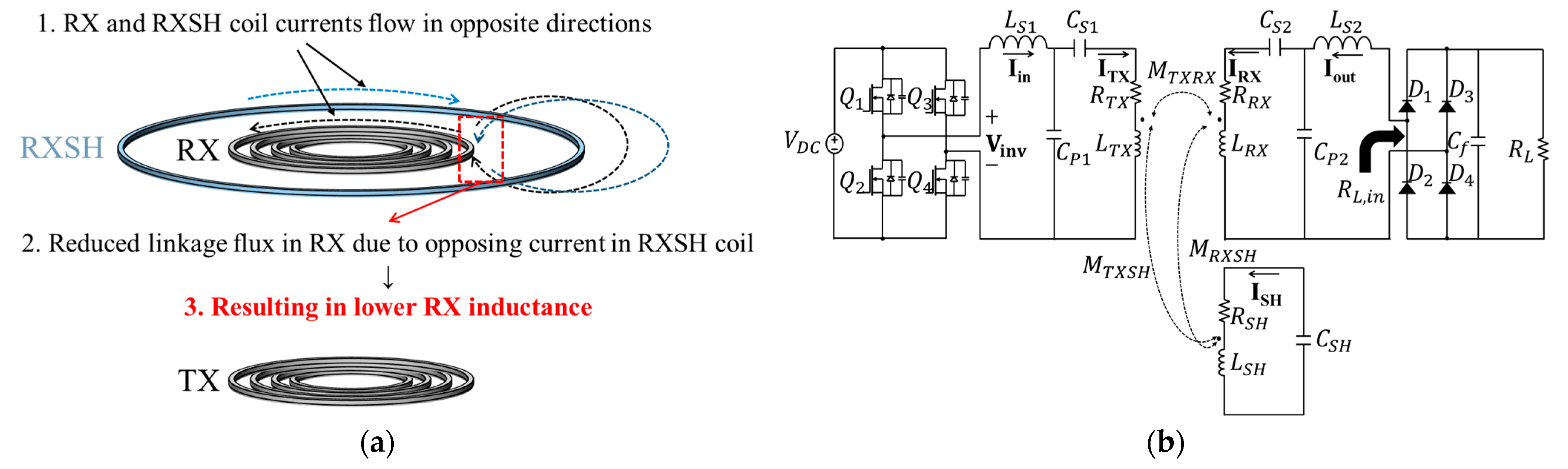
- The analytical modeling of the equivalent inductance variation in the main coil caused by the shielding coil: The introduction of a reactive shielding (SH) coil near the receiving (RX) coil changes the magnetic field distribution, which in turn reduces the equivalent inductance of the RX-side resonant loop. This paper derives analytical expressions that describe how the SH coil parameters affect the RX coil’s inductance. This modeling provides essential insights for accurately designing the resonant circuit in shield-integrated WPT systems.
- Resonant component redesign methodology: Using the derived expressions, we propose a capacitor selection method that eliminates the need for a series capacitor on the RX side and ensures zero-voltage switching (ZVS) or zero-phase-angle (ZPA) operation on the inverter of the TX side. This approach simplifies the circuit structure and improves the robustness of the design under EMF constraints.
- The analytical modeling of input voltage adjustment for output power regulation with a SH coil on the RX side: The reduced coupling caused by SH coil insertion lowers the induced voltage on the RX coil, necessitating an increase in the TX input voltage to maintain constant output power. We present an analytical formulation to predict this voltage shift, aiding system-level power regulation design.
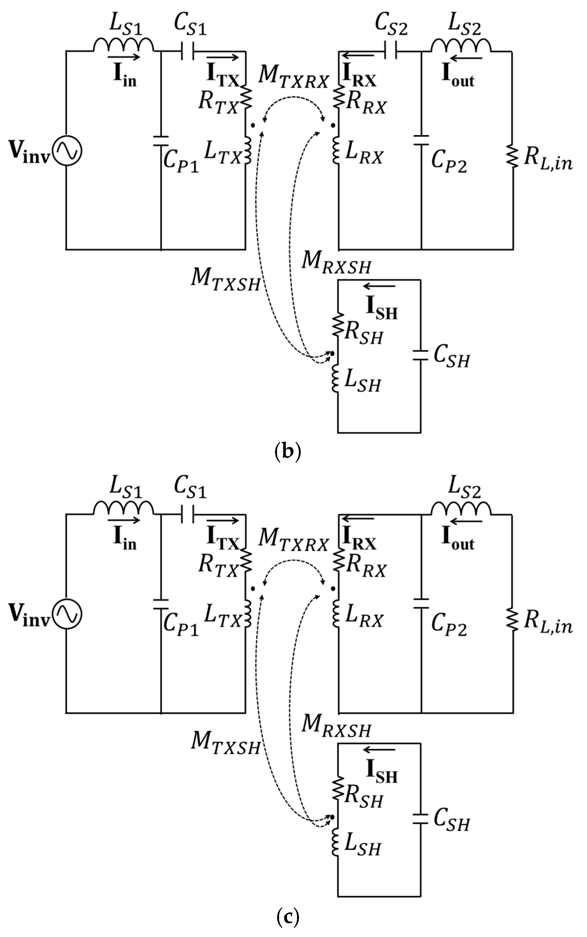
2. Design of LCC-LCC WPT Systems with a Shielding Coil in the Receiver Side
2.1. Analysis of RX Inductance Variation and Design of the SH Coil Resonance Frequency and Input Voltage
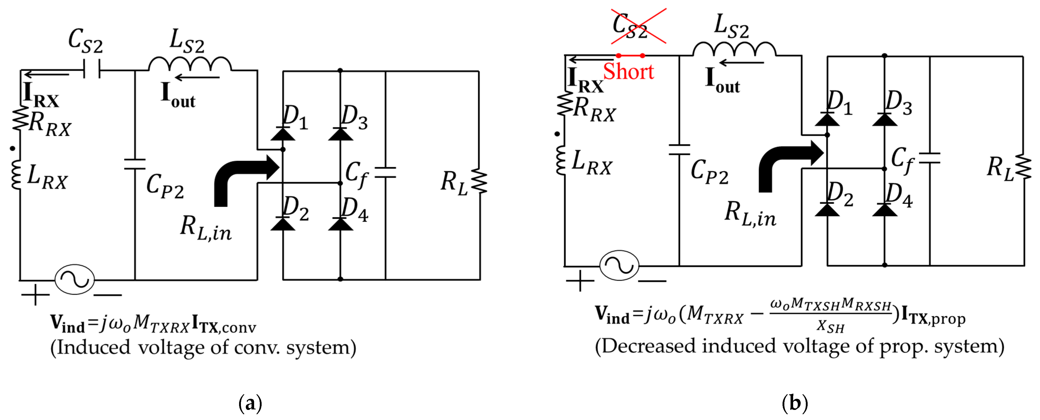
2.2. Selection of the Series Capacitor of the TX Side for Stable Inverter Operation
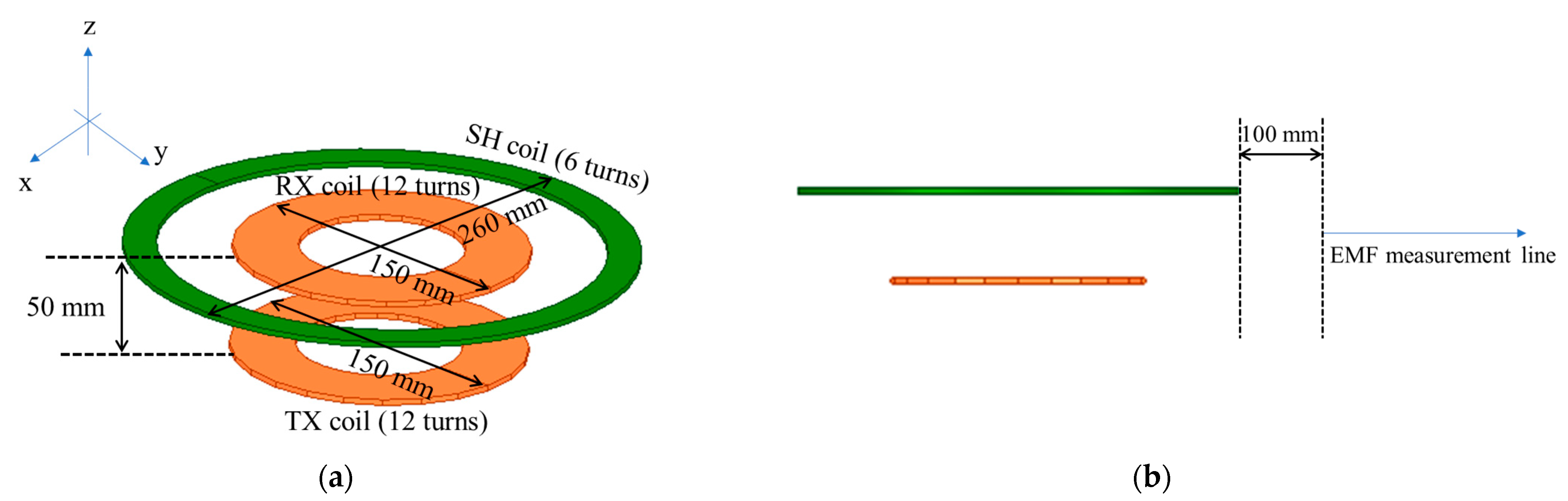
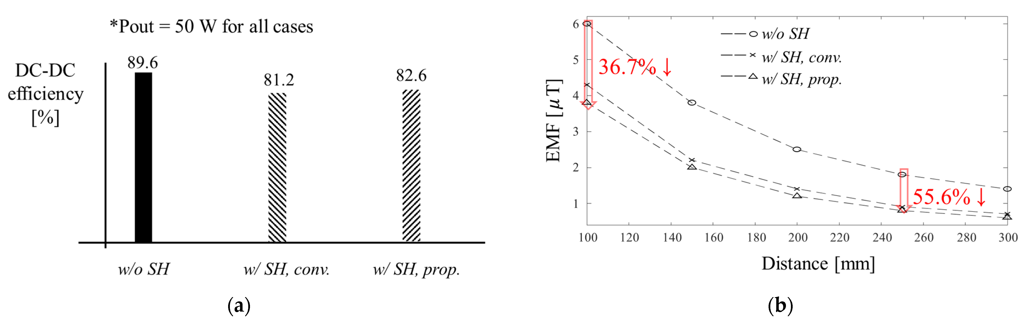
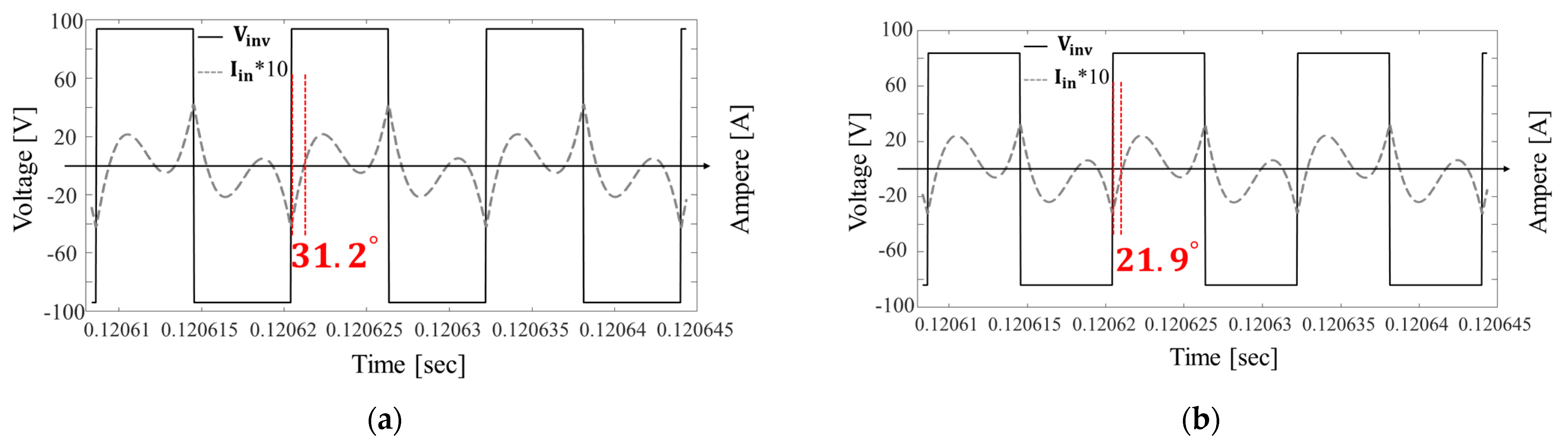
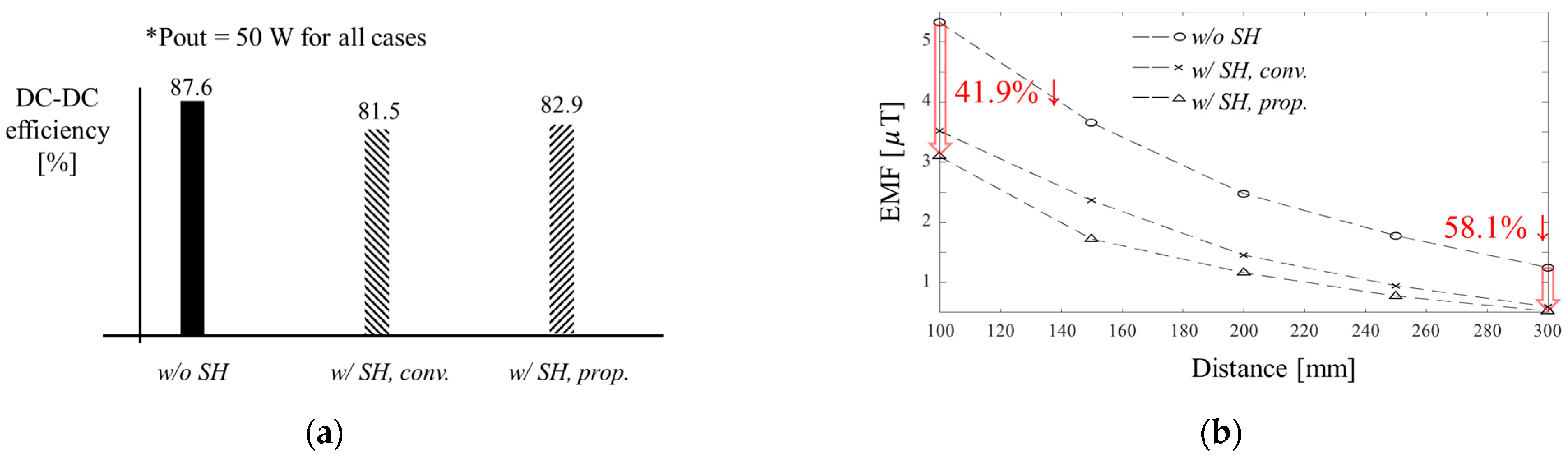
3. Validation of the Proposed Method
3.1. Simulation
3.2. Experiment
4. Conclusions
Author Contributions
Funding
Data Availability Statement
Acknowledgments
Conflicts of Interest
References
- Ahmad, A.; Alam, M.S.; Chabaan, R. A comprehensive review of wireless charging technologies for electric vehicles. IEEE Trans. Transp. Electrif. 2018, 4, 38–63. [Google Scholar] [CrossRef]
- Zhang, W.; Mi, C.C. Compensation topologies of high-power wireless power transfer systems. IEEE Trans. Veh. Technol. 2016, 65, 4768–4778. [Google Scholar] [CrossRef]
- Zhang, Z.; Pang, H.; Georgiadis, A.; Cecati, C. Wireless power transfer—An overview. IEEE Trans. Ind. Electron. 2019, 66, 1044–1058. [Google Scholar] [CrossRef]
- Kiani, M. Wireless power transfer and management for medical applications: Wireless power. IEEE Solid-State Circuits Mag. 2022, 14, 41–52. [Google Scholar] [CrossRef]
- Monti, G.; De Giovanni, G.R.; De Liso, M.; Pascali, M.; Tarricone, L. Wireless power transfer strategies for medical implants: Focus on robustness and EM compatibility. IEEE Microw. Mag. 2021, 22, 28–41. [Google Scholar] [CrossRef]
- Yoda, H. Development of WPT systems for railway vehicles and study for low-frequency application. In Proceedings of the 2024 IEEE Wireless Power Technology Conference and Expo (WPTCE), Kyoto, Japan, 8–11 May 2024; pp. 536–541. [Google Scholar]
- Ahn, J.; Woo, S.; Kim, H.; Song, K.; Huh, S.; Hong, S.E.; Kim, J.; Choi, H.D.; Ahn, S. An out-of-phase wireless power transfer system for implantable medical devices to reduce human exposure to electromagnetic field and increase power transfer efficiency. IEEE Trans. Biomed. Circuits Syst. 2022, 16, 1166–1180. [Google Scholar] [CrossRef]
- International Commission on Non-Ionizing Radiation Protection (ICNIRP). Guidelines for limiting exposure to time-varying electric, magnetic, and electromagnetic fields (up to 300 GHz). Health Phys. 1998, 74, 494–522. [Google Scholar]
- International Commission on Non-Ionizing Radiation Protection (ICNIRP). Guidelines for limiting exposure to time-varying electric and magnetic fields (1 Hz to 100 kHz). Health Phys. 2010, 99, 818–836. [Google Scholar] [CrossRef]
- Park, J.; Kim, D.; Hwang, K.; Park, H.H.; Kwak, S.I.; Kwon, J.H.; Ahn, S. A resonant reactive shielding for planar wireless power transfer system in smartphone application. IEEE Trans. Electromagn. Compat. 2017, 59, 695–703. [Google Scholar] [CrossRef]
- Elnait, K.E.I.; Huang, L.; Tan, L.; Wang, S.; Wu, X. Resonant reactive current shield design in WPT systems for charging EVs. In Proceedings of the 2018 IEEE PES Asia-Pacific Power and Energy Engineering Conference (APPEEC), Kota Kinabalu, Malaysia, 7–10 October 2018; pp. 56–59. [Google Scholar]
- Kim, J.; Ahn, S. Dual loop reactive shield application of wireless power transfer system for leakage magnetic field reduction and efficiency enhancement. IEEE Access 2021, 9, 118307–118323. [Google Scholar] [CrossRef]
- Gu, Y.; Wang, J.; Liang, Z.; Zhang, Z. Mutual-Inductance-Dynamic-Predicted Constant Current Control of LCC-P Compensation Network for Drone Wireless In-Flight Charging. IEEE Trans. Ind. Electron. 2022, 69, 12710–12719. [Google Scholar] [CrossRef]
- Tang, M.; Liu, W.; Zhang, W.; Zhao, C.; Hu, A.P. Robust Wireless Power Transfer for EVs by Self-Oscillating Controlled Inverters and Identical Single-Coil Transmitting and Receiving Pads. Energies 2023, 18, 211. [Google Scholar] [CrossRef]
- Li, X.; Yang, L.; Xu, Z.; Hu, J.; He, Z.; Mai, R. A Communication-Free WPT System Based on Transmitter-Side Hybrid Topology Switching for Battery Charging Applications. AIP Adv. 2020, 10, 045302. [Google Scholar] [CrossRef]
- Shin, Y.; Woo, S.; Lee, C.; Rhee, J.; Huh, S.; Ahn, S. Determination of current ratio to minimize power losses of coils in wireless power transfer system with double-sided LCC topology. In Proceedings of the 2022 Wireless Power Week (WPW), Bordeaux, France, 5–8 July 2022; pp. 95–98. [Google Scholar]
- Kim, H.; Kim, J.; Ahn, J.; Shin, Y.; Park, B.; Huh, S.; Choi, S.; Park, J.; Ahn, S. Determination of compensation capacitor considering the dead-time characteristics for ZVS in wireless power transfer system. IEEE J. Emerg. Sel. Top. Power Electron. 2023, 11, 2501–2513. [Google Scholar] [CrossRef]
- Fu, N.; Deng, J.; Wang, Z.; Wang, W.; Wang, S. A hybrid mode control strategy for LCC–LCC-compensated WPT system with wide ZVS operation. IEEE Trans. Power Electron. 2022, 37, 2449–2460. [Google Scholar] [CrossRef]
- Wang, X.; Xu, J.; Leng, M.; Ma, H.; He, S. A hybrid control strategy of LCC-S compensated WPT system for wide output voltage and ZVS range with minimized reactive current. IEEE Trans. Ind. Electron. 2021, 68, 7908–7920. [Google Scholar] [CrossRef]
- Wang, X.; Xu, J.; Mao, M.; Ma, H. An LCL-based SS compensated WPT converter with wide ZVS range and integrated coil structure. IEEE Trans. Ind. Electron. 2021, 68, 4882–4893. [Google Scholar] [CrossRef]


| Key Attributes | [10] | [11] | [12] | This Work |
|---|---|---|---|---|
| EMF reduction | O | O | O | O |
| Considering of effective inductance variation | X | X | X | O |
| Quantitative input voltage design | X | X | X | O |
| Resonant topology | SS | SS | SS | LCC-LCC |
| Elimination of RX-side series capacitor | X | X | X | O |
| Parameters | Values (μH) |
|---|---|
| 21.9 | |
| 21.9 | |
| 18.7 | |
| 4.5 | |
| 3.1 | |
| 4.5 |
| Parameters | Values | ||
|---|---|---|---|
| Case 1 (ref.) | Case 2 (Reactive SH ) | Case 3 (Reactive SH ) | |
| (kHz) | 85 | ||
| (V) | 56 | 94 | 84 |
| ( H) | 15 | ||
| (nF) | 233.7 | ||
| (nF) | 500 | 560 | |
| (nF) | 1752.9 | - | |
| (nF) | 176.2 | ||
| ( H) | 19.9 | ||
| (nF) | - | 410 | |
| (W) | 50 | ||
| (Ω) | 39 | ||
| Parameters | Values | ||
|---|---|---|---|
| Case 1 (ref.) | Case 2 (Reactive SH ) | Case 3 (Reactive SH ) | |
| 85 kHz | |||
| 60.2 V | 99.9 V | 88 V | |
| / | 20.8 H/39.6 mΩ | ||
| / | 20.1 H/38.6 mΩ | ||
| / | 18.8 H/41.9 mΩ | ||
| 4.0 H | |||
| 3.0 H | |||
| 4.1 H | |||
| / | 15.9 H/54.0 mΩ | ||
| / | 237.3 nF/4.9 mΩ | ||
| / | 569.3 nF/4.8 mΩ | 661.5 nF/ 4.0 mΩ | |
| / | 2036.2 nF/3.0 mΩ | - | |
| / | 188.8 nF/6.0 mΩ | ||
| / | 19.0 H/65.2 mΩ | ||
| / | - | 399.7 nF/3.5 mΩ | |
| 50 W | |||
| 44 Ω | |||
Disclaimer/Publisher’s Note: The statements, opinions and data contained in all publications are solely those of the individual author(s) and contributor(s) and not of MDPI and/or the editor(s). MDPI and/or the editor(s) disclaim responsibility for any injury to people or property resulting from any ideas, methods, instructions or products referred to in the content. |
© 2025 by the authors. Licensee MDPI, Basel, Switzerland. This article is an open access article distributed under the terms and conditions of the Creative Commons Attribution (CC BY) license (https://creativecommons.org/licenses/by/4.0/).
Share and Cite
Shin, Y.; Rhee, J.; Woo, S. Resonance Circuit Design Eliminating RX-Side Series Capacitor in LCC-LCC WPT Systems Using an RX Shield Coil. Electronics 2025, 14, 2686. https://doi.org/10.3390/electronics14132686
Shin Y, Rhee J, Woo S. Resonance Circuit Design Eliminating RX-Side Series Capacitor in LCC-LCC WPT Systems Using an RX Shield Coil. Electronics. 2025; 14(13):2686. https://doi.org/10.3390/electronics14132686
Chicago/Turabian StyleShin, Yujun, Jaewon Rhee, and Seongho Woo. 2025. "Resonance Circuit Design Eliminating RX-Side Series Capacitor in LCC-LCC WPT Systems Using an RX Shield Coil" Electronics 14, no. 13: 2686. https://doi.org/10.3390/electronics14132686
APA StyleShin, Y., Rhee, J., & Woo, S. (2025). Resonance Circuit Design Eliminating RX-Side Series Capacitor in LCC-LCC WPT Systems Using an RX Shield Coil. Electronics, 14(13), 2686. https://doi.org/10.3390/electronics14132686