The proposed MTMC tracking methodology consists of combining several techniques and includes the presentation of a new tracking algorithm that leverages the error patterns of the detector YoloV7, as well as the sequences of rapid bounding box size changes that appear in DOB, FE, and POL errors. In this manner our tracker offers a computationally inexpensive and effective solution. We call the new tracker Multi-Object Tracker based on Corner Displacement (MTCD).
Perspective transformation is used to obtain the positions of the bounding boxes in a plane with real size dimensions, and space constraints are denoted as the metric plane (MP). The positions of the vehicles in the MP allow for the construction of a graph of positions and relative distances between vehicles, which are called “object networks”, and they are useful for reducing FB, FPB, and FNB errors using a spatial analysis (SA) method.
2.3.1. Multi-Object Tracker Based on Corner Displacement
In the current case study, vehicles remain stationary several minutes and perform sudden rapid movements, such as lane changes or simply moving forward. Under these conditions, trackers based on the Intersection over Union (IOU) of bounding boxes and other more complex SORT-like trackers tend to lose more than 30% of vehicles due to the errors described in
Section 2.2. Based on the observed error patterns, a new multi-object tracking algorithm that is robust to those errors is proposed.
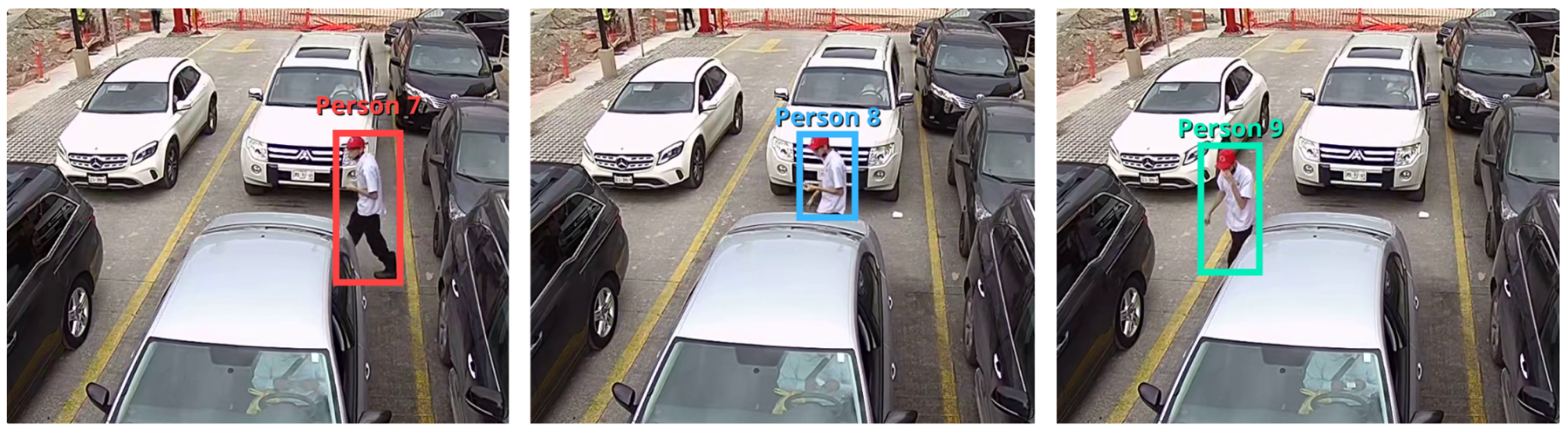
The pattern observed in DOB, FE, and POL errors shows that one of the sides of the BB experiences small displacements and size changes, while the dimension perpendicular to this side changes its magnitude considerably. A human observer watching the BBs through a sequence of frames perceives that the rectangle “stretches” or “contracts” in one direction. The MTCD leverages this characteristic. Thus, a comparison is made between the distances of the four corners of all bounding boxes with their analogues in the previous video frame.
Let
and
be two arbitrary BBs: one detected in video frame
i and the other in
, respectively (consecutive frames). The sides of the rectangles will be denoted as
,
,
, and
, and the notation
will be used to refer to the bottom side of object
. Each side is composed of two points, denoted as 0 and 1, where the order is established clockwise starting from the center of the rectangle. Thus, we can unequivocally express the point we are referring to by adding the index of the point in brackets to the side expression, e.g.,
. To express the calculation of the Euclidean distance between two points, we use the operator
, where
and
are any two points. Using these definitions the length of an arbitrary side of rectangle
can be define with Equation (
1).
Based on this definition, we have outlined the conditions for identifying the same object across consecutive frames in Equations (
2) and (
3).
Equation (
2) ensure that at least one of the sides is close to its position in the previous frame.
The third condition, expressed in Equation (
3), disambiguates intercepted rectangles when the dimensions of the unchanging side are different. When an object rapidly changes one of its dimensions, the bounding box dimension must be maintained to avoid DOB and POL errors, keeping the BB of the vehicle with its dimensions prior to the error. To detect rapid increases in BB size, the condition presented in Equation (
4) is used, where
represents the area of the bounding box of object
i.
The MTCD method is summarized in Algorithm 1.
| Algorithm 1 MTCD algorithm |
- 1:
for all frame in stream do - 2:
if it is the first frame then - 3:
Assign an ID number to each object - 4:
continue - 5:
end if - 6:
for all object in frame do - 7:
for all object in frame do - 8:
for all in [top, right, bottom, left] do - 9:
if Are satisfied conditions ( 2) and ( 3) then - 10:
is associated with , receiving its ID - 11:
if then - 12:
- 13:
end if - 14:
continue to next object in frame - 15:
end if - 16:
end for - 17:
end for - 18:
end for - 19:
end for
|
2.3.2. Method for Spatial Analysis
FB, FPB, and FNB errors result in catastrophic failure for MCT algorithms based on position overlap for the following reasons: A false positive in an FPB, when it occurs in FoV overlap zones, results in the association of multiple different objects or contamination. Each false negative can result in the loss of the trajectory of the vehicle; the fragmentation of bounding boxes into smaller boxes in the case of an FB causes more vehicle instances to be produced, leading to a loss of trajectory information and affecting both recall and precision. The new spatial analysis (SA) algorithm, described in this section allows for the preservation of information about interactions between vehicles and people despite these errors. It is based on the fact that there are multiple fragments of information, which can be connected depending on how their trajectories relate over time. The algorithm works in real time, but associations are not fully determined until vehicles leave the scene.
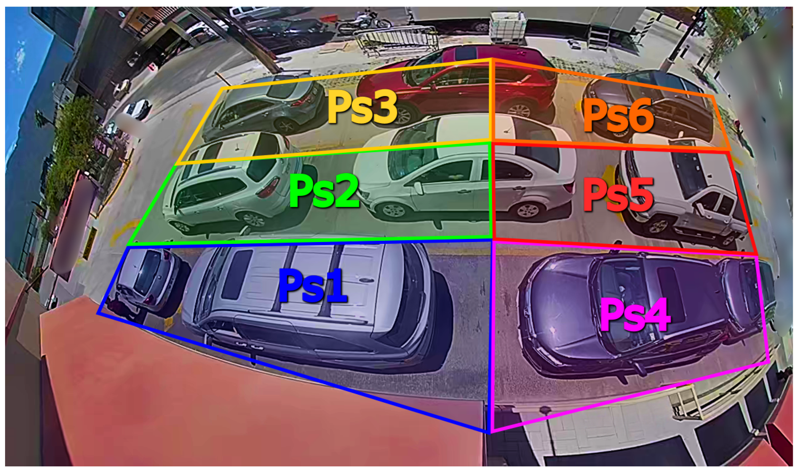
Vehicle positions are represented using a single point. We propose using the centre of the bounding box for vehicles and the centre of the top side for people. Any area traversable by vehicles must be covered with perspective transformation polygons, each with 4 vertices, corresponding to sections between 4 and 8 square meters, as observed in the yellow colour in
Figure 4. Using excessively large transformation polygons leads to errors due to the distortion introduced by the camera, which causes vehicles not to be projected onto the desired position on the plane. The ROIs must be small enough to reduce distortion error.
The next step is to obtain the coordinates of the projections of the transformation polygons onto the MP. The latter must contain recognizable features that aid in the positioning of the polygons; in our case, roof vertices and on-site measured distances in meters are used. For each polygon
, a pair of coordinate sets will be obtained: the projections of the polygon on the plane of camera
j are denoted by
, and its coordinates in the MP are denoted by
. Through direct linear transformation, the homography matrix that relates both sets of coordinates
is calculated. With this matrix, the homogeneous coordinates of a vehicle or person with an arbitrary ID
k, observed by camera
j and located within polygon
during video frame
h, are represented by
, where
and
correspond to its coordinates in pixels. The coordinates of the vehicle on the MP,
, can be approximated using the transformation of Equation (
5).
where
b is a bias factor that is eliminated by simple division.
It is necessary to perform a fine adjustment of the positioning of the polygon vertices so that the mapping of vehicles does not introduce errors into the algorithm. For this adjustment, the projections obtained from the vehicles in the MP must be compared with the expected position in the same plane. In this work, we performed the adjustment by trial and error, as the vehicles must be in the correct lane, and we used the observable features of the MP to validate the fit with the desired position.
For calculating the velocity of a vehicle
represented by
, a first-order approximation of the position derivative is used. The BB can move from one frame to another due to factors other than the car’s motion; thus the estimated position of the vehicle has an error that can be represented as white noise. To reduce the effect of position error in the calculated velocity, the velocity is filtered by taken the average of the last 5 frames as the instant velocity, as presented in Equation (
6).
The next step of the algorithm is to construct an abstract representation (AR) of each tracked object. An AR is a collection of information that contains, among other things, the trajectory of a tracked object. These trajectories are expressed in both the MP coordinates and BB coordinates of the frames of detection. The AR contain references to joints, which in this context refer to another abstract collection of data that represents the association between two objects. The joint contains references to the objects joined and the start time of the union. ARs also contain references to the joints that unite them, forming circular references.
In FoV overlap areas, joints can be generated between pairs of objects seen by multiple cameras, but not between objects from the same camera. Conversely, in the rest of the observed areas, only joints between pairs of objects from the same camera are allowed. The rule for creating a joint is that the coordinates of the objects must be within a distance less than threshold in the same frame. Joints can also be broken if, in the same frame, two objects united by it are at a distance greater than threshold . When an object joins a false positive with a joint and then moves away from it, the joint breaks, preserving its information. Also, if the BB of an object grows or displaces erroneously, briefly generating a joint with a nearby object, this joint should break when the objects separate.
Joints do not break when one of the objects disappears and thus allow the connecting of objects that were first observed in other cameras. The union between an active object and one that disappeared also allows for the transferring of information from a BB to fragments in case of an FB and then recovering the information when the original BB reappears.
Vehicles that are related to others due to a chain of joints and other vehicles belong to an object network (ON), which is a set in which all its elements should, ideally, be the same vehicle. ONs can temporarily include other vehicles and be “contaminated”; however, the proposed rules also allow ONs to be “cleaned,” containing the information of a single object at the end of their trajectories. Vehicles in an ON are not eliminated until time has elapsed since the last time any of its elements were observed.
When a vehicle with a new ID appears for the first time in an area far from FoV intersection zones or vehicle entry zones, it is assumed to be either a false positive or the end of a false negative. To validate the second case, a search is conducted among all inactive object networks for one that was last in a nearby position, with similar dimensions, within a time less than . As an additional condition to identify the end of an FNB, the speed of the vehicle before disappearing is analysed, and its value must be below the speed threshold . If all conditions are met, a joint is made with the disappeared object.
When there is more than one active instance of an object, the object position to create new joints is the average of the positions of the instances. The SA algorithm is condensed in Algorithm 2.
| Algorithm 2 Spatial analysis (SA) algorithm |
- 1:
for all video frames batch b do - 2:
for all camera c do - 3:
for all tracked object do - 4:
if is not vehicle class then - 5:
continue - 6:
end if - 7:
for all polygon do - 8:
if is inside then - 9:
project onto MP using Equation ( 5) - 10:
if already has an AR then - 11:
add new data - 12:
estimate instant velocity using Equation ( 6) - 13:
else - 14:
Create new AR instance - 15:
end if - 16:
end if - 17:
end for - 18:
end for - 19:
end for - 20:
for all each do - 21:
if is new and in a FoV area then - 22:
for all each other of same class do - 23:
if camera then - 24:
if then - 25:
joint(, ) - 26:
end if - 27:
end if - 28:
end for - 29:
else if is new in a non-FoV area then - 30:
for all each other of same class do - 31:
if camera then - 32:
if then - 33:
joint(, ) - 34:
end if - 35:
end if - 36:
end for - 37:
for all each other not active of same class do - 38:
if camera then - 39:
if and iou(, and last velocity of then - 40:
joint(, ) - 41:
end if - 42:
end if - 43:
end for - 44:
end if - 45:
for all in Network of do - 46:
if camera then - 47:
if then - 48:
unjoint(,) - 49:
end if - 50:
end if - 51:
end for - 52:
end for - 53:
end for
|
The bracket after indicates selecting the position in a batch corresponding to the letter inside. Note that ARs are sets of data that store the information of tracklets, and the ON is an abstract graph that connects them temporally.
2.3.3. Methods to Estimate Person–Vehicle Interaction
In the drive-thru case study, staff members first approach vehicles to take orders, then deliver the orders, and finally process payments. The objective of analysing staff–vehicle interactions is to measure the time elapsed from the initial staff interaction with the customer to the final interaction, which serves as a performance metric. In the proposed approach, staff–vehicle interactions are identified based on the distance between the person and the vehicle in the MP, the duration of the interaction, and the angle of interaction. Determining the relationship between the staff and vehicles in video frames is non-trivial because the relative distance in pixels between the vehicle and the person depends on both the actual distance between the objects and the camera, as well as camera distortion at the point of interaction.
For staff location, we also use abstract representations (ARs). However, they are not used to track people but rather to store the interaction. The staff always interacts with vehicles through the window of the driver. Using this fact, the interaction can be defined in terms of the relative position of the staff with respect to the vehicle when the staff is static. To evaluate this, follow the next steps: Let
be the abstract representation of a person in a batch of video frames “
b”, and let
be the abstract representation of a vehicle in the same frame; then
where
and
represent the distance in x and y, respectively, between both objects in meters in the MP coordinates. Therefore,
represents the unit vector of the position of the staff with respect to the vehicle. To calculate if the orientation of one with respect to the other is correct, an initial desired unit vector in MP coordinates is proposed, denoted by
, and finally, the attention conditions are represented by Equations (
8) and (
9).
where • represents a dot product.
When both conditions, distance Equation (
8) and orientation Equation (
9), are met, a person–vehicle joint is generated. This only store information about the beginning and end of the interaction. A person’s AR can contain many joints with various vehicle ARs and vice versa. Unlike vehicle–vehicle joints, person–vehicle joints do not break when both objects move away from each other. Instead, the break occurs when the interaction time between the person and the vehicle is less than the time threshold
. A person’s AR is not eliminated until all vehicles with which they maintain a joint are eliminated. Algorithm 3 shows how joints are formed between interactions of both types of objects:
| Algorithm 3 Person–vehicle interaction algorithm |
- 1:
for all video frames batch b do - 2:
for all camera c do - 3:
for all tracked object do - 4:
if is not person class then - 5:
continue - 6:
end if - 7:
for all polygon in service area do - 8:
if is inside then - 9:
project onto MP using Equation ( 5) - 10:
if already has an AR then - 11:
add new data - 12:
else - 13:
Create new AR instance - 14:
end if - 15:
end if - 16:
end for - 17:
end for - 18:
end for - 19:
for all active of class person do - 20:
for all active of class vehicle in service area do - 21:
Calculate using Equation ( 7) - 22:
if conditions ( 8) and ( 9) are met then - 23:
if joint[, ] exists then - 24:
update times of joint[AR, AR] - 25:
else - 26:
create joint[AR, ] - 27:
end if - 28:
end if - 29:
end for - 30:
end for - 31:
end for
|


 ,
, 


