1. Introduction
In the era of modern digital communication, the demand for high-speed, reliable, and energy-efficient data transmission is ever increasing. Technologies such as satellite communications, the broadband Internet, and digital video broadcasting rely heavily on robust encoding and decoding mechanisms to maintain data integrity and efficiency in the presence of noise and bandwidth limitations [
1]. The Digital Video Broadcasting–Return Channel via Satellite 2 (DVB–RCS2) standard has become a cornerstone for interactive satellite communication systems, where Turbo Codes are widely employed for their near-Shannon-limit error correction capabilities [
2,
3].
To meet the stringent performance and latency requirements of such systems, there is a growing emphasis on optimizing the computational aspects of Turbo encoders. A significant bottleneck in this domain arises from the interleaving operation, which plays a critical role in spreading burst errors but often involves irregular memory access patterns that hinder efficient parallel execution [
4].
Modern computing architectures, including multicore CPUs and SIMD (Single Instruction Multiple Data) vector units, offer substantial potential for accelerating encoding operations. However, many encoding algorithms remain inherently sequential or are poorly adapted to these hardware capabilities, resulting in the suboptimal utilization of computational resources [
4]. To address these limitations, it is essential to devise generic and reconfigurable strategies that restructure traditional sequential implementations into parallelizable and vector-friendly formats [
5,
6].
Such approaches involve not only rethinking memory access patterns but also creating algorithmic frameworks that align with the architectural strengths of modern processors. In this context, we propose a novel Reconfigurable Vector-Processed Interleaving Algorithm tailored specifically for the DVB-RCS2 Turbo encoder. The proposed approach is designed to exploit data-level parallelism, enhance memory access efficiency, and support reconfiguration for scalability across varying hardware platforms.
1.1. Error Correction
Wireless communication channels are inherently susceptible to various noise sources and interference, which can significantly degrade the integrity of transmitted information. As data transfer rates escalate to meet the demands of modern applications, there is an imperative need for encoding schemes that not only facilitate rapid data transmission but also ensure robust error detection and correction mechanisms. Forward Error Correction (FEC) techniques address this need by enabling the receiver to identify and correct errors without necessitating retransmission, thereby enhancing data reliability and reducing latency.
Turbo Codes (TCs), introduced in the early 1990s, marked a significant milestone by approaching the theoretical limits of channel capacity as defined by Shannon’s seminal work on information theory [
1,
7]. By incorporating redundant bits and leveraging iterative decoding processes, TC allows for effective error correction even in noisy environments. The fundamental principles of TC have been instrumental in shaping subsequent developments in error-correction methodologies.
In recent years, the landscape of FEC has evolved to meet the stringent requirements of next-generation wireless systems, including 5G and 6G networks [
8]. Emerging coding schemes such as Low-Density Parity-Check (LDPC) codes and Polar codes have gained prominence due to their superior error correction capabilities and suitability for high-throughput applications. These codes offer enhanced performance in terms of bit error rates and decoding efficiency, which makes them integral to modern communication standards.
Moreover, innovative approaches like the Error Correction Code Transformer have been proposed to unify various decoding strategies within a single framework [
9]. This Transformer-based architecture demonstrates the potential to handle multiple linear block codes, including LDPC and Bose–Chaudhuri–Hocquenghem (BCH) codes, thereby offering flexibility and efficiency in decoding processes. Such advances are pivotal in addressing the diverse error correction needs of contemporary wireless communication systems.
In addition, adaptive hybrid FEC schemes have been developed to dynamically respond to fluctuating channel conditions. For example, combining Reed–Solomon (RS) and LDPC codes with adaptive algorithms like Kalman filters enables real-time adjustments to coding parameters, optimizing error correction performance in scenarios such as video transmission over unreliable networks [
10,
11].
These progressive developments in error correction techniques underscore the ongoing commitment to improving data integrity and transmission efficiency in the face of evolving communication challenges [
12].
1.2. Turbo Encoders
TCs, a subdivision of the Parallel Concatenated Convolutional Codes family, are widely used, mainly because of their adjustability for the purpose of real-time implementations (e.g., in satellite communications [
13]). TCs are in use in wireless ATMs, Third-Generation systems and in video broadcasting [
12,
14]. Every TE is constructed by two main operation blocks: an interleaver and a convolution encoder. While the encoding is the purpose of a TE, interleaving causes substantial operation latency and performance skew. Interleaving is the action of creating a permutation of the input data by a deterministic shuffle.
Modulo calculations are a common tool used in programming implementations in order to keep the data in line with a finite vector size or memory allocated array. Modulo calculations are a hardware obstacle that needs to be addressed, especially when dealing with various and large modulo bases. In the TE interleaving block, the modulo is a repeated operation consuming both power and computation time. This article presents a vector-oriented implementation of the permutation stage of a specific TE described by the DVBRCS2 standard.
1.3. Vector Processor and Parallel Processing
A Vector Processor (VP) differs from a Scalar Processor (SP) by its ability to process a single instruction on multiple data. That is, a single operation is performed simultaneously on N independent elements (N being the given length of the vector). The VP can fetch N elements using a single load operation, thus saving time in both fetching and decoding the data and instructions [
15,
16]. In the VP architecture, it is essential to redefine operations while indicating whether the operation is performed on a scalar or a vector of a certain size. The vectors could be of constant/dynamic length. Vector Processors significantly accelerate data-parallel tasks such as multimedia encoding, digital signal filtering, and cryptographic computations [
17,
18,
19]. In Turbo Encoders, the interleaver must permute entire packets of bits—often millions of elements—in one operation, creating a processing bottleneck ideally addressed by SIMD-style vector units [
17].
Our simulations revealed that 78% of processing cycles were of this stage; therefore, improving the performance of the permutation algorithm will result with speedup of the whole application. Using a VP allows to efficiently manipulate the input data by adequate vector and parallel operations, thus enhancing the performance of the runtime application both in memory access (R/W) and in total cycles. The algorithmic solution presented in this paper is general and can be reconfigured by the basic DVB-RCS2 parameters.
1.4. Turbo Encoder Interleaving in DVB-RCS2 and Broader Applicability
The DVB-RCS2 system is a standardized specification developed to support interactive satellite communication services, primarily in broadband applications [
20]. One of the most demanding components of DVB-RCS2 is its Turbo Encoder, which provides strong Forward Error Correction (FEC) capabilities to ensure reliable transmission over high-latency, noisy satellite links [
13,
21].
The Turbo Encoder in DVB-RCS2 requires data interleaving through permutation functions, which depend on parameters
. These permutations are algebraically defined and dynamically vary depending on payload size and configuration [
13]. This results in a computational burden, especially for real-time embedded systems such as satellite modems or onboard processing units [
22].
Our algorithm specifically targets the permutation block in the Turbo Encoder, offering
Low-latency, real-time execution on vectorized DSPs (e.g., CEVA-XC4500) [
23];
A modular phase-based structure (Load–Execute–Store) which facilitates reconfigurability and portability;
Efficient memory access patterns and alignment with hardware instructions, improving both throughput and resource usage.
Broader Applicability
Beyond DVB-RCS2, the core structure of our algorithm—bit-level manipulation, dynamic permutation, and vectorized execution—can be adapted to similar systems, including the following:
DVB-S2X: This is an advanced broadcast and interactive satellite communication standard that also relies on interleaved FEC coding [
20,
24].
5G NR Uplink Control Channel (PUCCH): This is where interleavers and permutation-based coding are used in HARQ feedback [
25].
WiMAX and LTE Turbo Coding: They use similar permutation structures and may benefit from hardware-optimized interleaver implementations [
26].
SpaceWire and CCSDS standards: They may require error-correction schemes in onboard satellite data links [
27].
1.5. Related Work
The demand for ever-higher data rates has driven the development of specialized turbo-encoding hardware. Texas Instruments TCI6618 multicore DSP, for example, delivers up to 582 Mbps, while NXP MSC8157 SoC sustains 330 Mbps on similar workloads [
28]. Beyond DSPs, FPGA-based implementations on Xilinx Zynq UltraScale+ platforms have achieved throughputs exceeding 800 Mbps by exploiting deeply pipelined, parallel interleaver designs [
29]. More recently, heterogeneous SoCs like Intel’s Versal ACAP—with its onboard AI engines—have demonstrated Turbo Encoder rates up to 1.2 Gbps by offloading interleaving and encoding kernels to dedicated vector units [
30].
On the software side, fine-grained SIMD optimizations on AVX-512 and ARM-NEON architectures yield performance improvements of over 60% compared to scalar implementations [
31]. Building on these advances, our work introduces a novel algorithm that entirely eliminates modulo operations via vector-coalesced indexing, further boosting the interleaver throughput on modern VP architectures.
In addition to DSP and FPGA solutions, general-purpose GPUs have been leveraged to accelerate turbo encoding for scenarios requiring ultra-low latency. “GPU acceleration for Turbo encoding on modern architectures such as NVIDIA Ampere has been explored. Existing implementations achieve multi-hundreds of Mbps to low-Gbps throughput by parallelizing interleaver and Max-Log-MAP kernels across thousands of threads—providing sub-millisecond latency suitable for highly responsive communication systems [
32].
Recent ASIC research on Turbo and related channel coding has emphasized energy-efficient, high-throughput designs suited to next-generation radio systems. For instance, LTE-compliant Turbo decoder ASICs fabricated in 65 nm and 130 nm CMOS arrayed parallel architectures to achieve 300–400 Mbps throughput with under 200 mW power consumption [
33]. Similarly, ASN-coset code ASIC implementations in advanced nodes have demonstrated area efficiencies of 120 Gbps/mm² and power consumption near 100 mW [
29]. On the memory front, 3D-stacked logic-in-memory systems show that integrating near-memory compute tightly with high-bandwidth stacked DRAM can deliver substantial memory-bound performance gains [
34]. Taken together, these results indicate that custom memory hierarchies and 3D-stacked Turbo encoder ASICs designed with folded interleavers and near-memory compute could realistically achieve multi-gigabit throughput under sub-200 mW power budgets.
The organization of this paper is as follows:
Section 2 describes the specific TE implemented set by the DVB-RCS2 standard.
Section 3, describes the original serial permutation algorithm and implementation. This algorithm serves as a reference for the speedup factor calculations.
Section 4, describes the proposed vectorial and parallel permutation algorithm.
Section 5 describes portability and architectural considerations.
Section 6 describes the simulation-based analysis and depicts the results graphically. Finally,
Section 7 concludes the results and achievements and proposes future research possibilities.
2. The Turbo Encoder
Figure 1 depicts the TE implemented by the DVB-RCS2 standard. It has a coding rate of 1:3, meaning that for every input bit, there are three output bits. The input is a 2-bit stream denoted as A and B. The output codeword is composed of three couplets: (1) The original A and B couplet remains unchanged. (2) A and B are encoded by the ‘Encoder Core’, a convolutional calculation block. (3) N couplets are delayed and rearranged in the ‘Permutation’ block, then encoded via the ‘Encoder Core’ block.
The permutation stage of the TE is determined by five parameters,
and
, with ranges defined by the DVB-RCS2 standard, and vector size N, the number of couplets in bits. The specific parameters used in the implementation are in compliance with the DVB-RCS2 standard and are detailed in
Table 1 [
13].
The original A and B couple are unchanged.
A and B are encoded by the ‘Encoder Core’, a convolutional calculation block.
N couplets are delayed and rearranged in the ‘Permutation’ block, then encoded via the ‘Encoder Core’ block.
The permutation stage of the TE is determined by five parameters,
and
, with ranges defined by the DVB-RCS2 standard, and vector size
N (the number of couplets in bits). The specific parameters used in the implementation are in compliance with the DVB-RCS2 standard and are detailed in
Table 1 [
13].
Initial simulations running a simple existing serial implementation of this TE result in the permutation stage taking up to 78% of the application (cycle-wise) and show potential parallelism features such as repetitiveness modulo calculations which could be reconfigured to enhance performance.
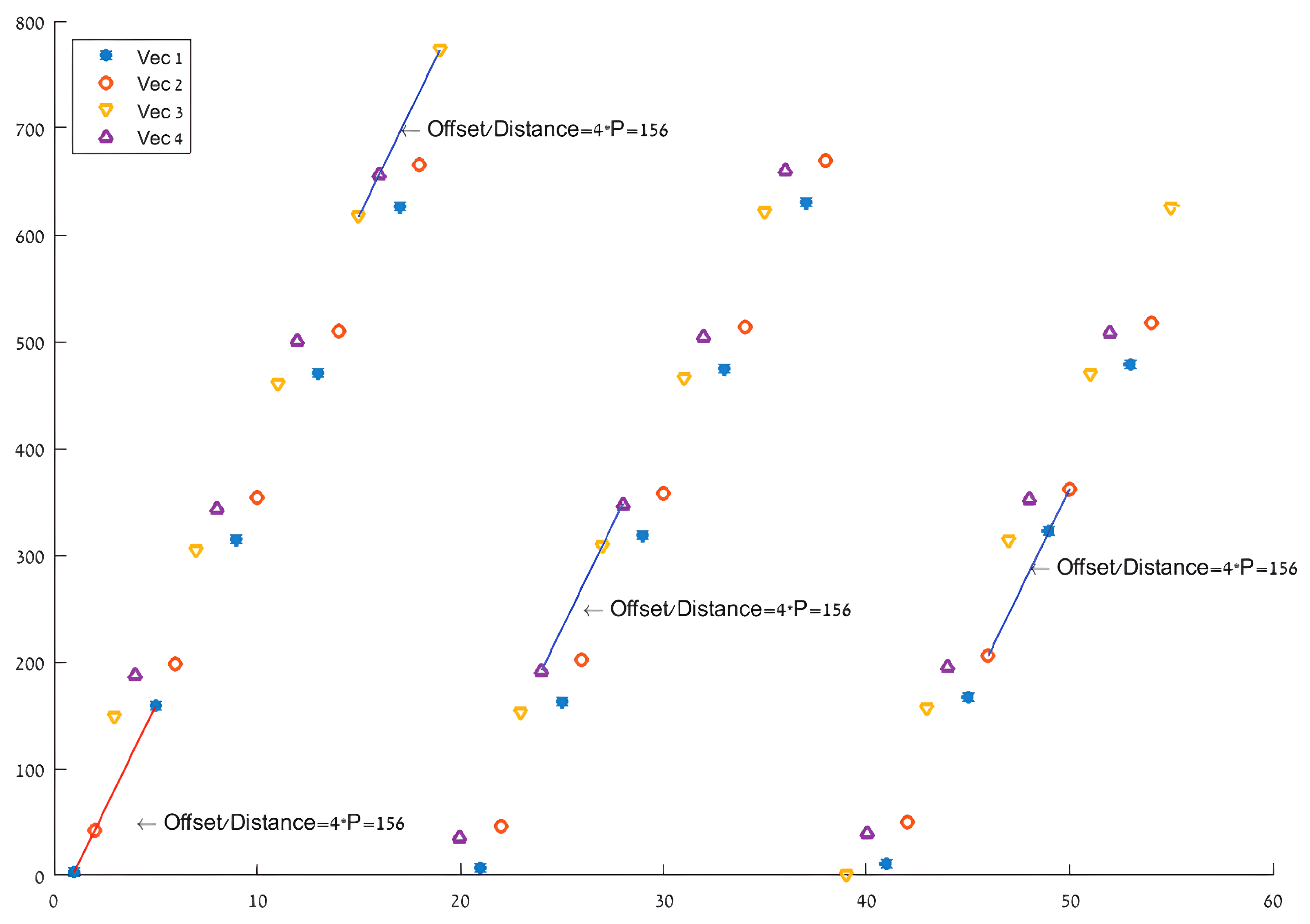
Figure 2 depicts an example of the permuted indexes by original indexes (for
and matching parameters from
Table 1) and shows the constant
incrimination leading to the new parallel approach described in
Section 4. The turbo encoder permutation stage is carried out in two levels.
- (1)
Describes a swap of the bit couplets for every odd-indexed component
- (2)
Describes a calculated rearrangement of the indexes based on the chosen parameters. Further elaboration of the latter can be found in
Section 4.
3. Serial Implementation
The serial implementation serves as a reference for speedup and relies on Look Up Tables (LUTs). For every input vector, given its length and matching parameters (taken from
Table 1), the program (i) creates a LUT by deterministic calculations matching the permutation indexes of each input bit, (ii) loads each bit and its designated new index, and (iii) stores the bit in a new output vector. This process is ineffective for two main reasons:
The LUT calculations are determined by the DVB-RCS2 standard.The modulo-based calculations are complex for any processor and are a changing parameter, disabling simple hardware solutions for these dynamic calculations. Given a finite collection of sets of vector length and parameters, saving all pre-calculated LUT is an option. However, real-time processors run on finite and usually small-sized program memory space (MS), bounding the MS that can be reserved for LUTs.
Saving the pre-calculated LUT in memory doesn’t solve the following issue. Once the LUT is calculated, the program loads bit-by-bit with its matching new index from the LUT, then the bit is stored to its designated index in the output vector. Loading and storing bit-by-bit (and index-by-index) results in excessive memory access.
The presented vector algorithm solves these problems by processing the data in max-sized streams (loading and storing more than one bit at a time) and by replacing the modulo-based calculations of the LUT with data and memory manipulations, resulting in lower run-time and memory access. The asymptotic tight bound computational complexity of the serial algorithm is .
4. New Approach: Parallel Vector Processing Based Algorithm
Using a Vector DSP with a Very Large Instruction Word (VLIW) architecture requires a different approach compared to the original straightforward approach detailed in
Section 3. The main idea is based on manipulating the data vector-wise instead of bit-by-bit and taking advantage of the modulo attributes originating from (2) and (3).
Figure 2 indicates modulo-induced strides from one index to the next. There are four different groups of indexes derived from the four cases in (3). These strides constitute the basis of the developed vector-wise algorithm described in the following subsections. The algorithm is based on configurable parameters defined by a standard, ensuring a comprehensive and generic solution, thus enabling further research possibilities as elaborated in
Section 7.
Basing the algorithm on Load–Execute–Store operations fitted with the CEVA-XC4500 DSP attributes creates phases. Each phase consists of iterations of execution operations that are performed in one work cycle of the DSP. The following subsections elaborate on these operations, which combined implement the permutation block of the TE. The presented algorithm was constructed for a specific VP and a specific TE but could be easily modified to various VPs and or different TEs. We chose to test and demonstrate the method on the CEVA-XC4500 and implement the TE described by the DVB-RCS2 standard.
4.1. Bit to Word
As in other DSP architectures, the CEVA-XC4500 DSP requires padding of the original input data for more efficient data manipulation. Hence, the first phase in the algorithm is padding every input data bit with 15 zeros. Consequently, every original input-data bit is now represented as one Word (16 bits) as shown in
Figure 3.
The CEVA-XC4500 DSP is capable of storing 512 bits in one store operation. Following that
, loading 32 bits of the original input-data stream will resolve in 512 bits of padded data as the result of one iteration of this phase. The number of iterations needed for all the original input-data stream to be processed is
, where N is the number of couplets in bits (see
Figure 1). Hence, the output vector of this phase is of size
[bits] or
[words].
Notes: The CEVA-XC4500 DSP is capable of storing 512 bits in one
store operation. Following that
, loading 32 bits of the original input-data stream results in 512 bits of padded data in one iteration of this phase. Therefore, the number of iterations needed for all the original input-data stream to be processed is
, where
N is the number of couplets in bits (see
Figure 1). Hence, the output vector of this phase is of size
[bits] or
[words].
Notes:
The permutation stage is identical to every two bits of the original input couplet (A and B), and so we refer to every padded couplet as a Double-Word (DW). In addition, the architecture of the CEVA-4500 DSP is designed to processes DWs; therefore, the next two phases of permutation are performed on N DWs.
The Bit-to-Word phase is added as an input rearrangement requirement of the specific DSP implementation. Four other processors will/will not require different input rearrangements, which will affect the results.
4.2. Transpose
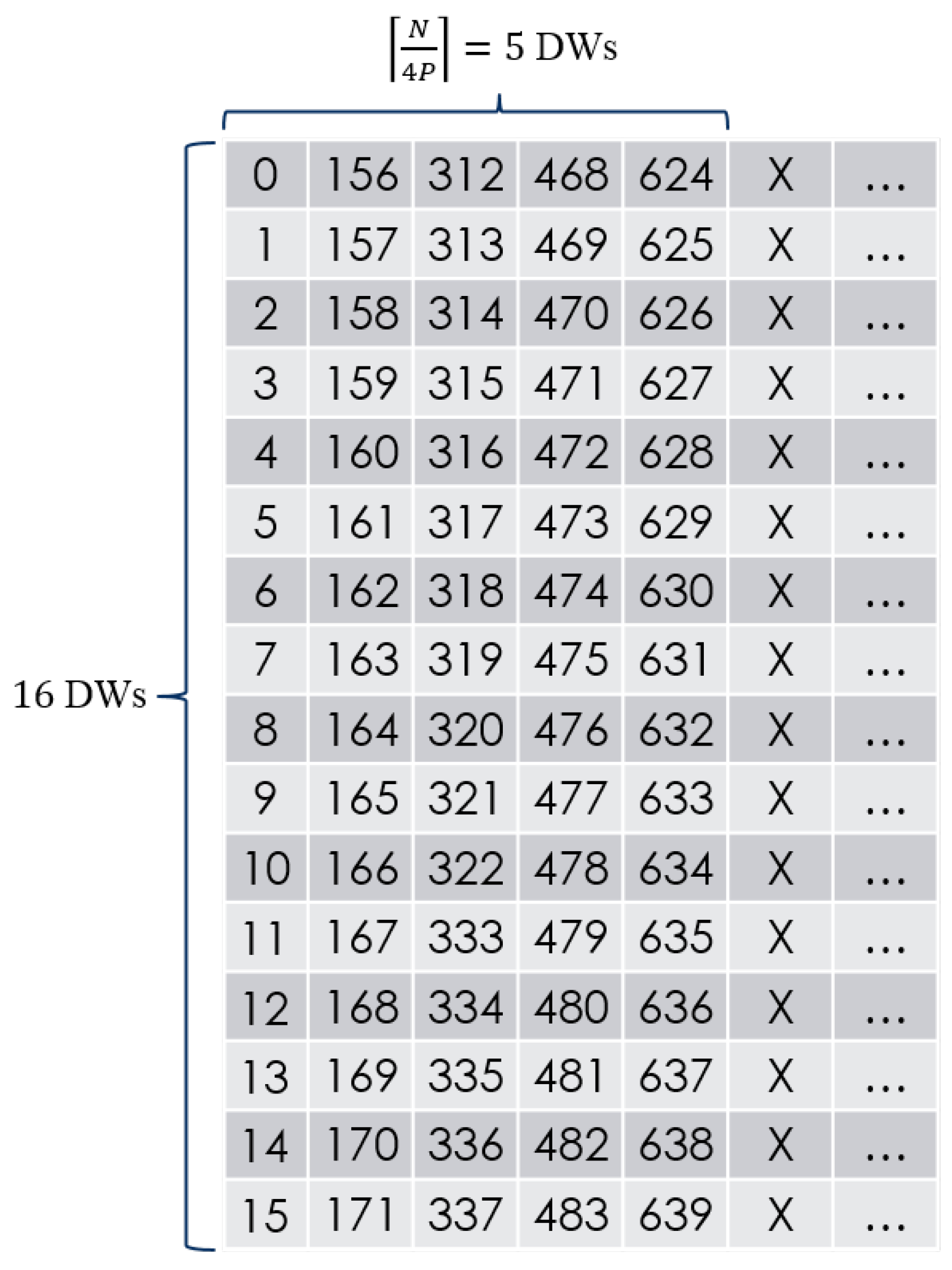
Referring to the input DW vector as a virtual 2D matrix of
, the vector is accessed with constant strides defined by the number of columns
as seen in
Figure 4. This virtual 2D matrix is transposed such that indexes
are the successors of indexes
j. The CEVA-XC4500 DSP best transposes blocks of
[DWs]; therefore, a block of 4 rows, each of 16 [DWs], is loaded from the memory.
Figure 5 shows an example first block of the virtual 2D matrix illustrated in
Figure 4. The
block to be transposed is defined by four rows of 16 consecutive DWs. The
row of block
i starts at
and
is the number of blocks to be transposed. The number of stuffed rows in the last block is
.
Figure 6 shows the same block illustrated in
Figure 5. Each row is stored in a continuous manner. The next row is stored at the end of the previous row. The next block rows are stored at the end of the previous block.
Notes:
An important part of this phase is swapping the words of odd-indexed (, ) DWs, meaning that in every odd-indexed DW, the high word and the low word are swapped. This swapping implements the permutation inside the bit-couplet as required. The CEVA-XC4500 DSP can swap words while loading any DW, meaning the bit-level swapping is implemented without influencing the processing time or memory access.
The chosen vector size and parameter sets used in simulations require transposing matrices of up to eight rows. An expansion of this algorithm for larger-sized matrices might be possible but was not simulated.
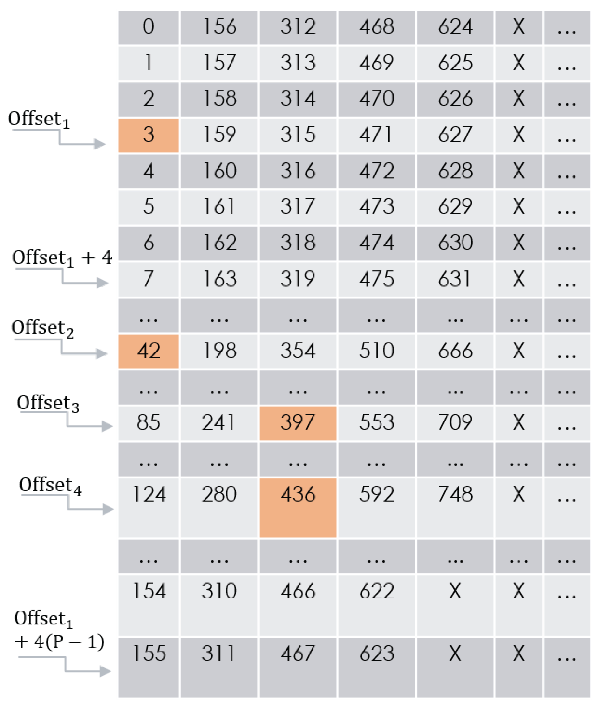
4.3. Concatenation
This phase creates four vectors by concatenating rows of the transposed 2D matrix of the previous phase. The four initial rows are chosen by four pre-calculated offsets determined by the DVB-RCS2 standard parameters , and P:
;
;
;
.
The strides taken from one row to the next are determined by . We continue and construct each vector by concatenating the row G from it. Knowing there are rows in the transposed 2D matrix and 4 vectors, consequently, there are concatenations to be performed.
Note: In
Figure 7, all row numbers must wrap around, keeping the index in range:
. Some parameter sets dictate a starting point for concatenation that is not the first DW of the first chosen row. The first DW for each
is defined by
Figure 8 depicts the virtual 2D matrix illustrated in
Figure 4. In this example
. Hence, using the expressions above, one may obtain
;
;
;
;
;
(always true since
);
,
;
.
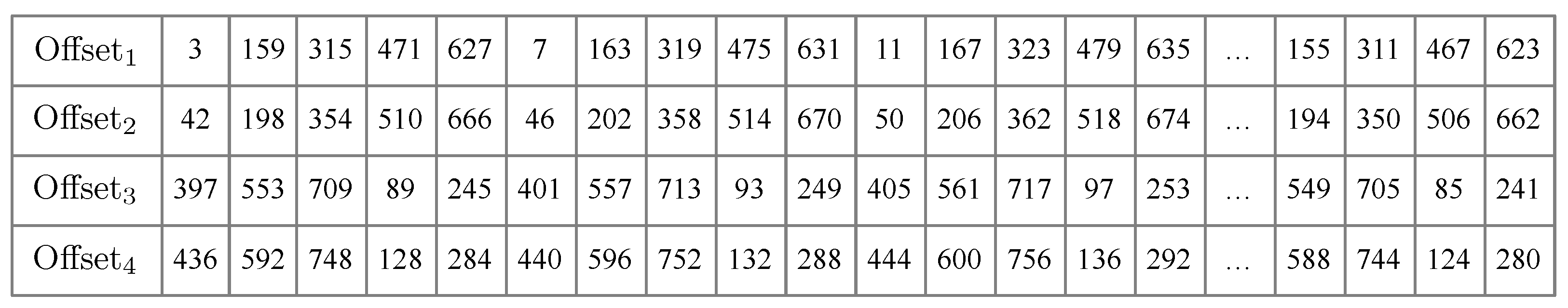
Figure 9 shows an example of the four result vectors in positions
, which are the output of the concatenation phase and serve as the input for the ordering phase.
4.4. Ordering
The ordering phase organizes its input as one long vector. This is achieved by loading the four vectors and transposing them using a similar transposition process to the one described in the transpose phase. Here, every iteration transposes blocks of [DWs] with the following differences:
The rows transposed are now stored in an orderly fashion, which match the desired output vector (no need for reconstruction of the transposed matrix).
The vectors are of the same size , meaning that stuffed data will exist only to fill the last block transposed.
Therefore, the number of blocks transposed is
, and the number of stuffed columns in the last block is
.
Figure 10 illustrates the
[DWs] matrix before reordering, and the output of this phase
N [DWs] after permutation (example).
4.5. Word to Bit
The final operation of the algorithm is unpadding the output vector of the ordering phase from the redundant zeros that were added to the original data in the ”bit to word” phase.
This concludes the vector-wise permutation stage implementation. Given
N bit couplets and matching parameters, following these phases, the result vector will contain
N bit couplets after permutation. The described are compatible with the DVB-RCS2 standard and are as generic as possible, having little data adjustments to best fit CEVA’s DSP and being able to be reconstructed to fit any VP with very few and minor changes to the overall algorithm. The asymptotic tight bound computational complexity of the vector-wise algorithm can be written as
5. Portability and Architectural Considerations
The proposed algorithm, while currently implemented and optimized for the CEVA-XC4500 DSP, is designed with portability in mind. Its structure and computational logic are not inherently tied to any CEVA-specific hardware features. Rather, the algorithm is built upon a general Load–Execute–Store (LES) model, which is applicable across a wide range of parallel and vector processing architectures.
5.1. SIMD-Based Processor Architectures
The algorithm’s parallelizable structure makes it suitable for Single Instruction, Multiple Data (SIMD) platforms such as ARM NEON and Intel AVX-512:
Vector operations used in the CEVA VLIW DSP correspond directly to SIMD instructions, such as fused multiply-add, shuffle, and permutation operations [
23].
Memory access patterns, designed for predictable strides or block memory regions, align well with SIMD memory models that favor aligned loads and stores [
35].
The required modifications include adapting the vector width, register usage, and instruction scheduling according to the target architecture’s instruction set and vector length (e.g., 128-bit for NEON, 256/512-bit for AVX2/AVX-512) [
36,
37].
5.2. Adaptation to FPGA Platforms
The phased structure of the algorithm (Load → Execute → Store) aligns naturally with hardware description paradigms:
Each phase can be pipelined in a hardware design, allowing concurrent execution and reduced latency [
38].
Data access regularity makes it feasible to construct dedicated memory controllers and buffer interfaces using standard RTL or HLS tools [
39,
40].
The deterministic operation flow makes the algorithm highly suitable for static scheduling and resource sharing—both essential in FPGA-based designs [
41].
5.3. Required Modifications for Portability
To adapt the algorithm to other platforms, the following components must be reconsidered:
Vector Register Width and Alignment: Modify the iteration tiling or blocking strategy based on the available register width and alignment requirements [
35,
42].
Instruction Mapping: Replace CEVA-specific VLIW operations with equivalent SIMD instructions or pipelined hardware operators.
Memory Layout Adjustments: Adapt the memory access code to fit the memory hierarchy and bus architecture of the new platform (e.g., cache-coherent memory on ARM vs. block RAM on FPGA).
Threading/Concurrency: For multicore CPUs or GPUs, introduce parallelism at a coarser granularity using OpenMP, CUDA, or thread-level task splitting [
43].
6. Simulations and Results
Performance analysis was carried out using the CEVATOOLBOX profiler designed for CEVA’s DSPs. The profiler creates a table detailing (1) the cycle count of each function in the code and total cycle count results and (2) the number of
Read/
Write operations performed in each function and total
Read/
Write results. Unlike the approach of enhancing each function of a code/algorithm individually, the proposed vector implementation revises the whole permutation process. Hence, serial and vector algorithms are fundamentally incompatible; therefore, we consider only the overall results of the permutation stage detailed in
Table 2.
The simulations were executed for 11 vector sizes and matching parameter sets given in
Table 2. For each parameter set, we compared the serial and vector-wise results and calculated the speedup using
where
and
are the counts of read, write, and total cycles of the serial- and vector-wise implementations, respectively.
Figure 11 illustrates the measured speedup factors for read, write, and total cycle counts across eleven vector sizes ranging from 56 bits to 2396 bits. Each cluster of three bars corresponds to a single vector size on the x-axis, with the height of the blue, orange, and green bars indicating the speedup achieved in the read operations, write operations, and overall cycle count, respectively.
Several trends are apparent:
Read speedup grows rapidly with the vector size, peaking at 734.5× for N = 1192 bits before tapering off at the largest size.
Write speedup also increases, with its maximum of 484.4× again at N = 1192 bits, reflecting the efficiency of coalesced vector writes.
Total-cycle speedup shows substantial gains, exceeding 296× at N = 492 bits and remaining above 124× at the maximum vector size.
The non-monotonic variations particularly in total-cycle speedup stem from parameter-dependent algorithm phases (e.g., number of blocks per transpose) rather than the vector size alone. Overall, even at the smallest vector length, the parallel interleaver consistently outperforms the serial baseline, confirming the effectiveness of our vector-wise implementation.
As shown, the algorithm maintains linear complexity with respect to vector size, and the performance improves due to the efficient memory access patterns enabled by the vectorized architecture. In particular, the ratio of read/write cycles to the total execution cycles remains stable, demonstrating the model’s predictable scaling behavior. This efficiency makes the proposed solution viable for real-time applications, even as data payload sizes grow.
The memory footprint was also monitored during these runs and remained bounded due to the fixed-size permutation buffers reused across iterations, which supports practical implementation in embedded environments.
7. Conclusions and Future Work
In this work, we have introduced a novel Reconfigurable Vector-Processed Interleaving Algorithm for the DVB-RCS2 Turbo Encoder, designed specifically to exploit the SIMD and VLIW features of modern DSP architectures. By restructuring the interleaving stage around Load–Execute–Store phases and eliminating costly per-bit modulo operations through vector-coalesced indexing, our approach outperforms the traditional serial implementation in every tested scenario.
The vector-wise algorithm implementation outperforms the serial implementation for all tested cases. Speedups were achieved even though the DSP hardware required padding and unpadding of the original data and the final result, respectively. A hardware that is better fit for the parallel algorithm, enabling the Transpose, Concatenation, and Ordering phases to be executed on bits rather than words, will improve the superiority of the parallel algorithm over the serial implementation.
Comprehensive profiling on the CEVA-XC4500 platform, using the CEVA-Toolbox profiler, demonstrated consistent speedups across eleven vector sizes: up to 7.3× read, 4.8× write, and 3.4× total cycle reductions (see
Table 2 and
Figure 11). These gains were achieved despite the overheads of data padding and alignment required by the DSP hardware, underscoring the robustness of the vector-wise method even on non-ideal architectures [
44].
Beyond the raw throughput, the vector-wise algorithm offers strong scalability: its parameter-driven design directly maps onto different DVB-RCS2 block lengths and puncturing rates without code restructuring. This reconfigurability makes it a prime candidate for integration into next-generation satellite modems and multicore SoCs, where both flexibility and high performance are critical.
Future work will involve a detailed power consumption analysis of the algorithm across different hardware configurations, with an emphasis on low-power satellite and IoT systems. We also plan to explore the scalability of the algorithm under broader parallel processing architectures, such as multicore vector DSPs or SIMD-capable FPGAs. Additional optimizations will investigate adaptive parameter tuning to maximize throughput and energy efficiency depending on varying vector sizes and system constraints.
Author Contributions
Conceptualization, M.B., O.B. and S.G.; methodology, M.B., O.B. and S.G.; software, M.B. and O.B.; validation, M.B. and O.B.; formal analysis, M.B. and O.B.; writing—original draft preparation, M.B., O.B., S.G. and Y.B.-S.; writing—review and editing, M.B., E.M., S.G. and Y.B.-S.; visualization, M.B., O.B. and Y.B.-S.; supervision, S.G. and Y.B.-S.; project administration, S.G. and Y.B.-S. All authors have read and agreed to the published version of the manuscript.
Funding
This research received no external funding.
Data Availability Statement
Data are contained within the article.
Conflicts of Interest
The authors declare no conflict of interest.
References
- Berrou, C.; Glavieux, A.; Thitimajshima, P. Near Shannon limit error-correcting coding and decoding: Turbo-codes. 1. In Proceedings of the ICC ’93 Geneva: IEEE International Conference on Communications, Geneva, Switzerland, 23–26 May 1993; Volume 2, pp. 1064–1070. [Google Scholar] [CrossRef]
- Djellouli, M.R.; Chouakri, S.A.; Ghaz, A. Performance of the Duo-Binary Turbo Codes in DVB-RCS2 System. Telecommun. Radio Eng. 2024, 83, 43–54. [Google Scholar] [CrossRef]
- Xue, Q.; Wang, J.; Chen, M.; Tang, X.; Zhu, J. Efficient receiver for dvb-rcs2 synchronization problems. In Proceedings of the 2023 4th Information Communication Technologies Conference (ICTC), Nanjing, China, 17–19 May 2023; pp. 167–171. [Google Scholar]
- Xue, Q.; Wang, J.; Chen, M.; Tang, X.; Zhu, J. Code-aided Synchronization for DVB-RCS2. In Proceedings of the 2023 IEEE 98th Vehicular Technology Conference (VTC2023-Fall), Hong Kong, China, 10–13 October 2023; pp. 1–6. [Google Scholar]
- Rowshan, M.; Qiu, M.; Xie, Y.; Gu, X.; Yuan, J. Channel coding towards 6G: Technical overview and outlook. IEEE Open J. Commun. Soc. 2024, 5, 2585–2685. [Google Scholar] [CrossRef]
- Fritschek, R.; Schaefer, R.F. MinGRU-Based Encoder for Turbo Autoencoder Frameworks. arXiv 2025, arXiv:2503.08451. [Google Scholar]
- Shannon, C.E. A mathematical theory of communication. Bell Syst. Tech. J. 1948, 27, 379–423. [Google Scholar] [CrossRef]
- Pennanen, H.; Hänninen, T.; Tervo, O.; Tölli, A.; Latva-aho, M. 6G: The Intelligent Network of Everything—A Comprehensive Vision, Survey, and Tutorial. arXiv 2024, arXiv:2407.09398. [Google Scholar]
- Yan, Y.; Zhu, J.; Zheng, T.; He, J.; Dai, L. Error Correction Code Transformer: From Non-Unified to Unified. arXiv 2024, arXiv:2410.03364. [Google Scholar]
- Xiong, Y.; Liu, Z.; Xu, L.; Hua, X.; Wang, Z.; Bi, T.; Jiang, T. Adaptive Hybrid Forward Error Correction Coding Scheme for Video Transmission. ZTE Commun. 2024, 22, 85. [Google Scholar]
- Cai, S.; Zhao, S.; Ma, X. Free ride on LDPC coded transmission. IEEE Trans. Inf. Theory 2021, 68, 80–92. [Google Scholar] [CrossRef]
- Du, X. Performance Analysis of Several Common Error Correction Codes. Appl. Comput. Eng. 2023, 14, 211–219. [Google Scholar] [CrossRef]
- Douillard, C.; Jezequel, M.; Berrou, C.; Tousch, J.; Pham, N.; Brengarth, N. The Turbo Code Standard for DVB-RCS. In Proceedings of the International Symposium on Turbo Codes and Related Topics (ISTC), Brest, France, 4–7 September 2000; pp. 535–538. [Google Scholar]
- Oletu, G.; Rapajic, P. The performance of turbo codes for wireless communication systems. In Proceedings of the 2011 3rd International Conference on Computer Research and Development, Shanghai, China, 11–13 March 2011; Volume 4, pp. 346–349. [Google Scholar] [CrossRef]
- Sordillo, S.; Cheikh, A.; Mastrandrea, A.; Menichelli, F.; Olivieri, M. Customizable Vector Acceleration in Extreme-Edge Computing: A RISC-V Software/Hardware Architecture Study on VGG-16 Implementation. Electronics 2021, 10, 518. [Google Scholar] [CrossRef]
- Lee, A.; Patel, R.; Kumar, S. Vector-Processing for Mobile Devices: Benchmark and Analysis. arXiv 2023, arXiv:2309.02680. [Google Scholar]
- Wang, Z.; Li, M.; Chen, R. Vectorization Programming Based on HR DSP Using SIMD. Electronics 2023, 12, 2922. [Google Scholar] [CrossRef]
- Smith, J.; Müller, A. Support Post-Quantum Cryptography with SIMD Everywhere on ARMv8. In Proceedings of the ICPP Workshops ’24: The 53rd International Conference on Parallel Processing Workshops, Gotland, Sweden, 12–15 August 2024. [Google Scholar] [CrossRef]
- Zhao, T.; Ye, Z. ZeroVex: A Scalable and High-performance RISC-V Vector Processor Core for Embedded Systems. In Proceedings of the 2024 IEEE 35th International Conference on Application-specific Systems, Architectures and Processors (ASAP), Hong Kong, China, 24–26 July 2024; pp. 32–33. [Google Scholar] [CrossRef]
- Digital Video Broadcasting (DVB). Second Generation DVB Interactive Satellite System (DVB-RCS2); Part 2: Lower Layers for Satellite Standard. 2012. Available online: https://dvb.org/?standard=dvb-rcs2-lower-layer-satellite-specification (accessed on 1 March 2025).
- Benedetto, S.; Montorsi, G. Unveiling turbo codes: Some results on parallel concatenated coding schemes. IEEE Trans. Inf. Theory 1996, 42, 409–428. [Google Scholar] [CrossRef]
- Ghosh, A.; Zhang, J.; Andrews, J.G.; Muhamed, R. Fundamentals of LTE; Prentice Hall: Hoboken, NJ, USA, 2010. [Google Scholar]
- CEVA DSP Architecture. Available online: https://www.ceva-dsp.com (accessed on 11 June 2025).
- ETSI. Digital Video Broadcasting (DVB); Second Generation Framing Structure, Channel Coding and Modulation Systems for Broadcasting, Interactive Services, News Gathering and Other Broadband Satellite Applications. Part II: S2-Extensions (DVB-S2X). 2005, pp. 22–27. Available online: https://dvb.org/?standard=second-generation-framing-structure-channel-coding-and-modulation-systems-for-broadcasting-interactive-services-news-gathering-and-other-broadband-satellite-applications-part-2-dvb-s2-extensions (accessed on 11 June 2025).
- TS 138 211 V16.4.0— NR; Physical Channels and Modulation. European Telecommunications Standards Institute (ETSI): Sophia Antipolis, France, 2020. Available online: https://www.etsi.org/deliver/etsi_ts/138200_138299/138211/16.04.00_60/ts_138211v160400p.pdf (accessed on 11 June 2025).
- Andrews, J.G.; Ghosh, A.; Muhamed, R. Fundamentals of WiMAX; Prentice Hall: Hoboken, NJ, USA, 2007. [Google Scholar]
- CCSDS 131.0-B-3; TM Synchronization and Channel Coding—Blue Book. CCSDS: Washington, DC, USA, 2017. Available online: https://ccsds.org/Pubs/131x0b5.pdf (accessed on 1 March 2025).
- Nordmark, O. Turbo Code Performance Analysis Using Hardware Acceleration. 2016. Available online: https://www.diva-portal.org/smash/get/diva2:1098448/FULLTEXT01.pdf (accessed on 11 June 2025).
- Tong, J.; Wang, X.; Zhang, Q.; Zhang, H.; Dai, S.; Li, R.; Wang, J. A High-Throughput Hardware Implementation of GN-Coset Codes. arXiv 2020, arXiv:2004.09897. [Google Scholar]
- Brown, N. Exploring the Versal AI engines for accelerating stencil-based atmospheric advection simulation. In Proceedings of the 2023 ACM/SIGDA International Symposium on Field Programmable Gate Arrays, Monterey, CA, USA, 12–14 February 2023; pp. 91–97. [Google Scholar]
- Pohl, A.; Cosenza, B.; Juurlink, B. Vectorization cost modeling for NEON, AVX and SVE. Perform. Eval. 2020, 140, 102106. [Google Scholar] [CrossRef]
- Tian, J.; Rivera, C.; Di, S.; Chen, J.; Liang, X.; Tao, D.; Cappello, F. Revisiting Huffman coding: Toward extreme performance on modern GPU architectures. In Proceedings of the 2021 IEEE International Parallel and Distributed Processing Symposium (IPDPS), Portland, OR, USA, 17–21 June 2021; pp. 881–891. [Google Scholar]
- Studer, C.; Benkeser, C.; Belfanti, S.; Huang, Q. Design and Implementation of a Parallel Turbo-Decoder ASIC for 3GPP-LTE. IEEE J.-Solid-State Circuits 2011, 46, 95–106. [Google Scholar] [CrossRef]
- Mutlu, O.; Ghose, S.; Gómez-Luna, J.; Ausavarungnirun, R.; Sadrosadati, M.; Oliveira, G.F. A Modern Primer on Processing in Memory. arXiv 2020, arXiv:2012.03112. [Google Scholar]
- Hennessy, J.L.; Patterson, D.A. Computer Architecture: A Quantitative Approach, 6th ed.; Morgan Kaufmann: Burlington, MA, USA, 2019. [Google Scholar]
- Intel Corporation. Intel® 64 and IA-32 Architectures Optimization Reference Manual. 2022. Available online: https://www.intel.com/content/www/us/en/content-details/671488/intel-64-and-ia-32-architectures-optimization-reference-manual-volume-1.html (accessed on 11 June 2025).
- Wang, K.C. ARMv8 Architecture and Programming; Springer International Publishing: Cham, Switzerland, 2023; pp. 505–792. [Google Scholar]
- Maxfield, C. The Design Warrior’s Guide to FPGAs; Newnes: Oxford, UK, 2004. [Google Scholar]
- Kuon, I.; Rose, J. Measuring the gap between FPGAs and ASICs. IEEE Trans. Comput.-Aided Des. Integr. Circuits Syst. 2007, 26, 21–30. [Google Scholar] [CrossRef]
- Cong, J.; Liu, B.; Neuendorffer, S.; Noguera, J.; Vissers, K.; Zhang, Z. High-level synthesis for FPGAs: From prototyping to deployment. IEEE Trans. Comput.-Aided Des. 2011, 30, 473–491. [Google Scholar] [CrossRef]
- Coussy, P.; Morawiec, A. High-Level Synthesis: From Algorithm to Digital Circuit; Springer: Berlin/Heidelberg, Germany, 2008. [Google Scholar]
- Karrenberg, R.; Hack, S. Whole-function vectorization. In Proceedings of the International Symposium on Code Generation and Optimization (CGO 2011), Chamonix, France, 2–6 April 2011; pp. 141–150. [Google Scholar] [CrossRef]
- OpenMP Architecture Review Board. OpenMP Application Programming Interface Version 5.0; OpenMP Architecture Review Board: Beaverton, OR, USA, 2018. [Google Scholar]
- Schubert, C.; Ott, M. Specialized Scalar and SIMD Instructions for Error Correction Codes Decoding on RISC-V Processors. IEEE Access 2024, 12, 762–775. [Google Scholar]
| Disclaimer/Publisher’s Note: The statements, opinions and data contained in all publications are solely those of the individual author(s) and contributor(s) and not of MDPI and/or the editor(s). MDPI and/or the editor(s) disclaim responsibility for any injury to people or property resulting from any ideas, methods, instructions or products referred to in the content. |
© 2025 by the authors. Licensee MDPI, Basel, Switzerland. This article is an open access article distributed under the terms and conditions of the Creative Commons Attribution (CC BY) license (https://creativecommons.org/licenses/by/4.0/).


 ,
, 


