1. Introduction
With the increasing global reliance on renewable energy, offshore wind power is experiencing rapid development due to its advantages, such as large-scale wind farms and stable wind speeds [
1,
2,
3]. By 2050, offshore wind power is expected to become a cornerstone of global decarbonization efforts [
4]. As wind farms are being constructed farther from the coast, transmission distances can extend up to hundreds of kilometers [
5]. High-voltage alternating current (HVAC) transmission faces challenges in long-distance submarine cables, such as excessive capacitive currents and high line losses [
6,
7]. In contrast, high-voltage direct current (HVDC) transmission has emerged as the preferred solution for long-distance offshore wind power transmission due to its high efficiency, the elimination of reactive power compensation requirements, and cost-effectiveness [
8,
9].
Modular multilevel converter (MMC)-based voltage-source converter (VSC-HVDC) systems enable bidirectional active and reactive power control while providing black-start capability. However, their extensive use of power electronic devices results in larger sizes, higher costs, and significantly increased investment and maintenance challenges for offshore platforms [
10,
11]. Compared to MMC converters, diode rectifier units (DRUs) offer higher reliability, lower cost, and more compact size [
12]. Nevertheless, pure DRUs cannot support reverse power flow or independently form a grid, making it difficult to meet the requirements for AC voltage formation, black-start functionality, and reactive power support in offshore wind farms [
13]. Most existing studies rely on wind turbines with inherent grid-forming capabilities, but this approach often leads to increased control complexity or higher costs [
14].
To meet the requirements of AC voltage formation and black-start capability in offshore wind farms while reducing costs, academia has proposed various hybrid topologies combining DRU and MMC technologies. A typical DRU-MMC system leverages the unidirectional conduction characteristic of the DRU, where the DRU handles the majority of power transmission during normal operation, while the MMC only needs to handle around 30% of the rated power, significantly reducing construction costs [
15]. References [
16,
17,
18] propose connecting the DRU and a small-capacity MMC in parallel on the AC or DC side. Here, the MMC provides grid-forming capability to establish AC voltage while its power reversal capability enables black-start power supply for the offshore wind farm and reactive power support for the DRU. However, due to the DC voltage withstand limitations of the power electronic devices, the offshore MMC still requires hundreds of submodules, resulting in relatively large size and weight, making it difficult to meet the economic requirements of offshore wind grid integration. References [
19,
20,
21] propose a series-connected DRU-MMC configuration on the DC side, forming the offshore converter station. Since the offshore MMC only needs to withstand part of the DC voltage, the required number of submodules is significantly reduced, leading to lower equipment costs and footprints, thereby improving the economic feasibility of offshore wind integration. However, due to the series connection between the DRU and MMC, as well as the unidirectional power flow characteristic of the DRU, the offshore wind farm cannot directly absorb power from the onshore grid for startup. Moreover, the rated DC voltages of the offshore and onshore MMCs are unequal, requiring the onshore MMC to operate in step-down mode, making black-start implementation challenging under this topology.
To overcome this problem, researchers have proposed various solutions, such as deploying diesel generators, energy storage systems, or parallel-connected AC cables from existing offshore platforms. Reference [
22] suggested using internal power sources like diesel generators at offshore wind farms to achieve black-start for power transmission systems. However, the operation and maintenance of these internal power sources increase investment costs. Reference [
23] proposed drawing an AC cable from an existing offshore AC system in wind power transmission networks to enable black-start in DRU-HVDC-based wind farms. However, this approach has significant limitations, as it relies on pre-existing offshore wind collection systems. Reference [
24] introduced DC-side directly connected energy storage to DRU-MMC systems, achieving black-start and frequency support for wind farms. Nevertheless, the inclusion of energy storage increases construction and investment costs. Reference [
25] presented a method using an onshore full-bridge and half-bridge hybrid MMC to enable step-down DC voltage operation during the initial startup phase for black-start capability. However, the surge in the number of required switching devices reduces the economic feasibility of offshore wind grid integration. In summary, further research is still needed to achieve a highly cost-effective black-start solution for fully grid-following DRU-MMC series-connected HVDC systems.
For fault detection and handling in DC systems, reference [
26] presents a combined relay–converter overcurrent protection scheme. Reference [
27] introduces a fault detection and isolation technique for multi-terminal DC microgrids. However, research on faults during black-start processes remains limited. This paper provides a brief analysis of the current and voltage protection configurations and fault handling during black-start operations.
To address the aforementioned challenges, this paper proposes a four-stage black-start strategy based on the switching of an auxiliary step-down transformer on the onshore MMC. The proposed method achieves black-start capability and wind turbine grid synchronization for fully grid-following offshore wind farms without requiring full-bridge submodules or energy storage systems. This approach significantly reduces costs by simply adding a small-capacity step-down transformer at the onshore converter station and leveraging the controllable components within the DRU-MMC system through proper switching and control strategies. The simulation results demonstrate excellent system stability performance under this strategy.
The structure of this paper is organized as follows:
Section 1 presents the introduction, outlining the research background and motivation;
Section 2 introduces the DRU-MMC series topology for offshore wind power transmission systems and analyzes its steady-state control principles;
Section 3 elaborates, in detail, on the proposed black-start strategy and its control implementation process;
Section 4 validates the proposed strategy’s effectiveness through PSCAD/EMTDC simulation studies;
Section 5 compares five black-start strategies;
Section 6 concludes the paper and discusses potential future research directions.
2. System Topology and Control Principles
2.1. System Topology
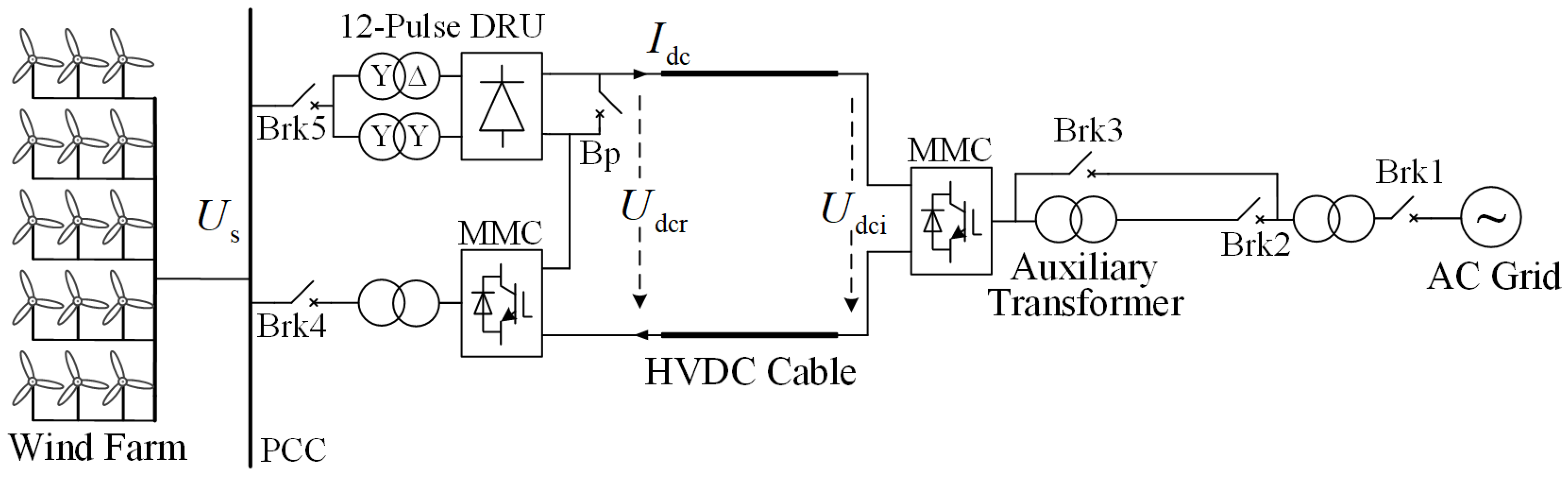
The topology of an offshore wind power DC transmission system based on a series-connected DRU-MMC hybrid converter is shown in
Figure 1. The offshore hybrid converter consists of a 12-pulse DRU and an auxiliary half-bridge MMC, where
represents the DC voltage of the hybrid converter formed by the series connection of the DRU and MMC on the DC side,
denotes the DC voltage of the onshore inverter MMC, and
is the DC current of the hybrid converter. Both the DRU and MMC are connected to the offshore wind farm collection point on the AC side, where
signifies the AC grid-side bus voltage of the rectifier station. An AC circuit breaker Brk5 is installed on the DRU’s AC side, while a DC bypass switch Bp is configured on the DC side. The onshore station comprises a half-bridge MMC. Direct-drive wind turbines interface with the offshore platform via AC collection before transmission to the onshore converter station through the series-connected DRU-MMC hybrid converter. A low-capacity auxiliary step-down transformer is installed on the onshore station’s AC side. Bypass switches Brk2 and Brk3 regulate the auxiliary transformer’s engagement and disengagement during black-start procedures.
2.2. Steady-State Characteristics of the DRU
In the 12-pulse DRU, the following fundamental relationships can be established:
where
denotes the RMS voltage at the converter transformer’s valve side,
is the DC current,
is the DC active power, and
is the commutation reactance. Using (1)–(3), the active power of the DRU can be expressed as:
According to (4), it can be deduced that when the DC voltage of the DRU remains constant, its active power exhibits a positive correlation with the valve-side voltage . Consequently, during steady-state operation, the active power output of the DRU can be effectively regulated by adjusting the voltage at the converter terminal.
2.3. Control Strategy for Onshore MMC
The steady-state control of the onshore MMC comprises two parts: DC voltage control and reactive power control. The active component of the control system maintains a constant DC bus voltage. However, an improper selection of the DC voltage reference value may lead to operational instability. Specifically, setting this reference too low can cause a voltage mismatch between the MMC’s DC port and the valve-side voltage, potentially resulting in severe overmodulation that could compromise system stability. Meanwhile, the reactive power component regulates the AC-side reactive power output. This capability allows for flexible reactive power adjustment in response to grid-connected AC system requirements. Through this control strategy, the onshore MMC can stabilize the DC-side voltage under various operating conditions while maintaining reactive power balance in the system, thereby providing the foundation for subsequent black-start operations.
2.4. Control Strategy for Offshore Auxiliary MMC
The auxiliary MMC regulates the offshore PCC voltage through a dual-loop control strategy while simultaneously suppressing second-harmonic circulating currents. Since the offshore auxiliary MMC and the DRU are connected in series on the DC side, they share the same DC current, whereas the DC voltage of the DRU varies with the current. Consequently, variations in the transmission power of the series-connected hybrid converter directly influence the terminal voltage of the offshore MMC. To ensure DC voltage stability in both the MMC and DRU under fluctuating transmission power, an additional PI loop is integrated into the conventional V/f control of the MMC. The deviation between the measured DC-side voltage of the MMC and the reference DC voltage is processed by the PI loop, with its output serving as the reference value for the outer-loop d-axis voltage component. The
-V/f control and traditional V/f control can be switched during black-start to compensate for DC voltage variations encountered in the black-start process. The corresponding control block diagram is illustrated in
Figure 2.
When the offshore MMC switches to traditional V/f control, the d-axis reference value of the outer-loop controller is held constant to maintain the offshore PCC voltage at a predetermined level. Upon adopting the additional DC voltage control strategy in the auxiliary MMC, the DC voltages of both the MMC and DRU remain stable despite variations in wind power. If wind power decreases, resulting in a decline in DC voltage, the controller responds by reducing the voltage amplitude at the PCC. This adjustment elevates the MMC’s DC voltage back to its reference value, simultaneously restoring the DRU’s DC voltage to its rated level. The additional DC voltage controller can be expressed as:
3. Black-Start Control Strategy
3.1. Four-Stage Operational Process
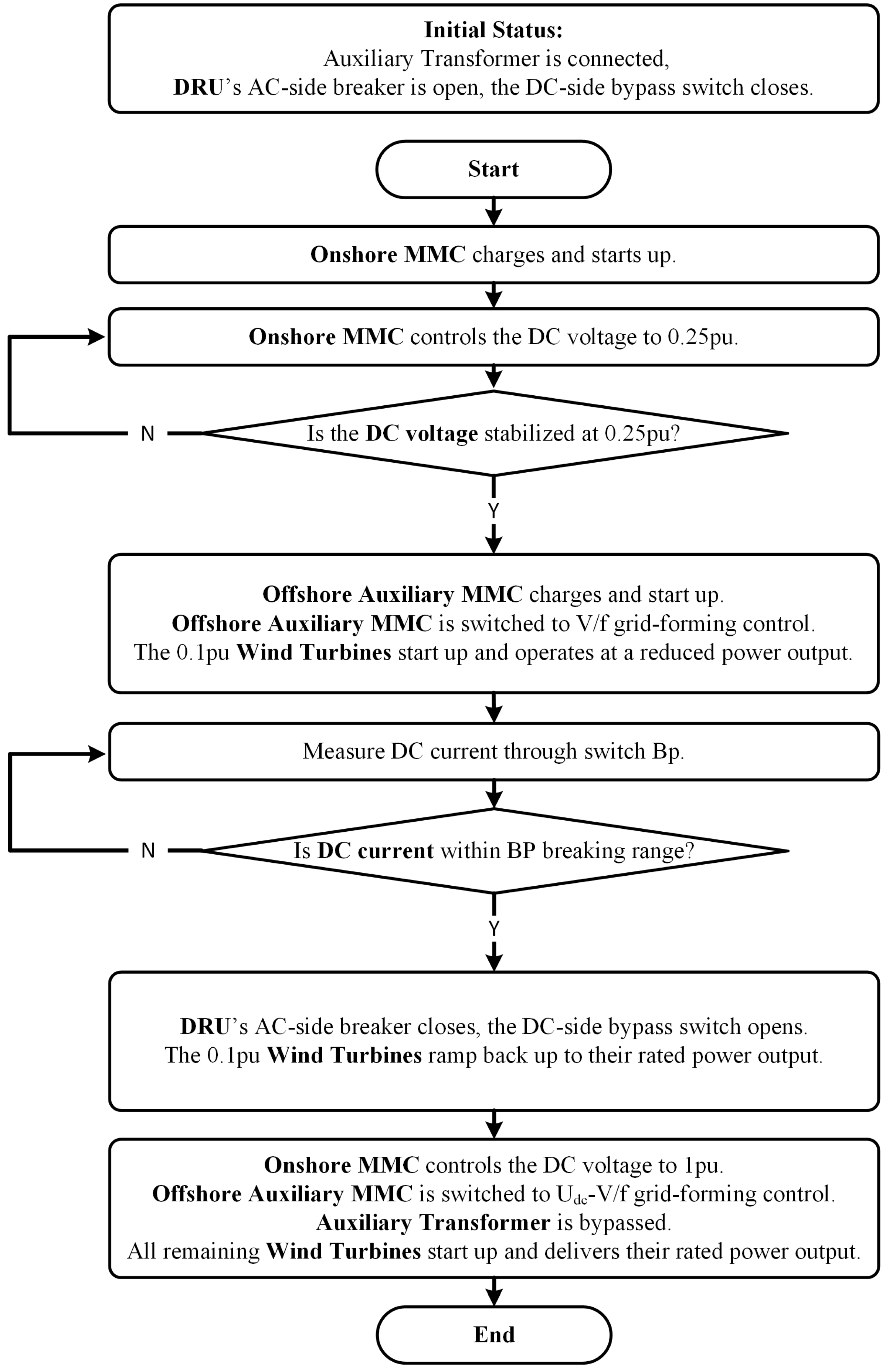
Building upon the steady-state control strategy discussed in
Section 2, this chapter elaborates on the black-start process and specific control procedures for the offshore wind power DC transmission system based on the series-connected DRU-MMC hybrid converter. The proposed black-start strategy comprises four stages, with the complete black-start control flowchart shown in
Figure 3.
Stage 1
During the initial stage of black-start, the submodule capacitor voltages in all converters are zero, and no voltage is present on the DC side of the system. The DRU’s AC-side circuit breaker Brk5 is open, while the DC-side bypass switch Bp is closed. The small-capacity step-down transformer in the onshore MMC converter station remains connected. By closing the AC circuit breaker Brk1, the onshore grid charges the submodule capacitors in the onshore MMC. Once the capacitor energy is sufficient for control operation, the onshore MMC is activated, and control is enabled. The active power component then regulates the DC-side voltage to maintain a constant 0.25 pu. Owing to the presence of the low-capacity step-down transformer, the valve-side voltage of the onshore MMC is maintained at a relatively low level, thereby allowing the DC-side voltage to be regulated to 0.25 pu.
Stage 2
The offshore MMC draws active power from the onshore MMC through the DC line to charge its submodule capacitors. Once the capacitor energy is sufficient for control, the offshore MMC engages V/f grid-forming control. Subsequently, a pre-selected subset of wind turbines, representing 0.1 pu of the wind farm’s rated capacity, is started and synchronized with the offshore AC system. Their active power output is then governed through real-time communication and supplementary control algorithms. This ensures that the DC current transmitted through the DC line by the offshore converter is reduced during the startup process, enabling the successful disengagement of the DRU’s DC-side bypass switch.
Stage 3
Since the wind turbines are currently outputting only a small amount of active power, the offshore converter transmits minimal active power to the DC side. Consequently, the DC current flowing through bypass switch Bp remains well within its breaking capacity limits. Subsequently, the DRU’s AC-side switch Brk5 closes, while its DC-side bypass switch Bp opens, bringing the DRU into operation. Through communication, the wind turbines are then released from their active power output limitations, enabling their active power output to increase.
Stage 4
Following the full integration of the DRU-MMC series hybrid converter into the DC system, the onshore MMC ramps up its DC voltage reference from 0.25 pu to 1 pu. During this transition, the submodule capacitors accumulate energy, resulting in a corresponding increase in capacitor voltage. Concurrently, the auxiliary MMC implements additional DC voltage control to maintain system voltages within safe operational limits and prevent any equipment from exceeding its rated voltage. Subsequently, Brk3 is closed, while Brk2 is opened, bypassing the low-capacity step-down transformer on the onshore MMC’s AC side. This operation enables the valve-side voltage of the MMC to its designated steady-state value. Finally, the remaining wind turbines are progressively commissioned and synchronized with the offshore AC system, enabling the wind farm to achieve full rated power output. As a result of this, the black start of the DC system is completed.
3.2. Communication During Black-Start Process
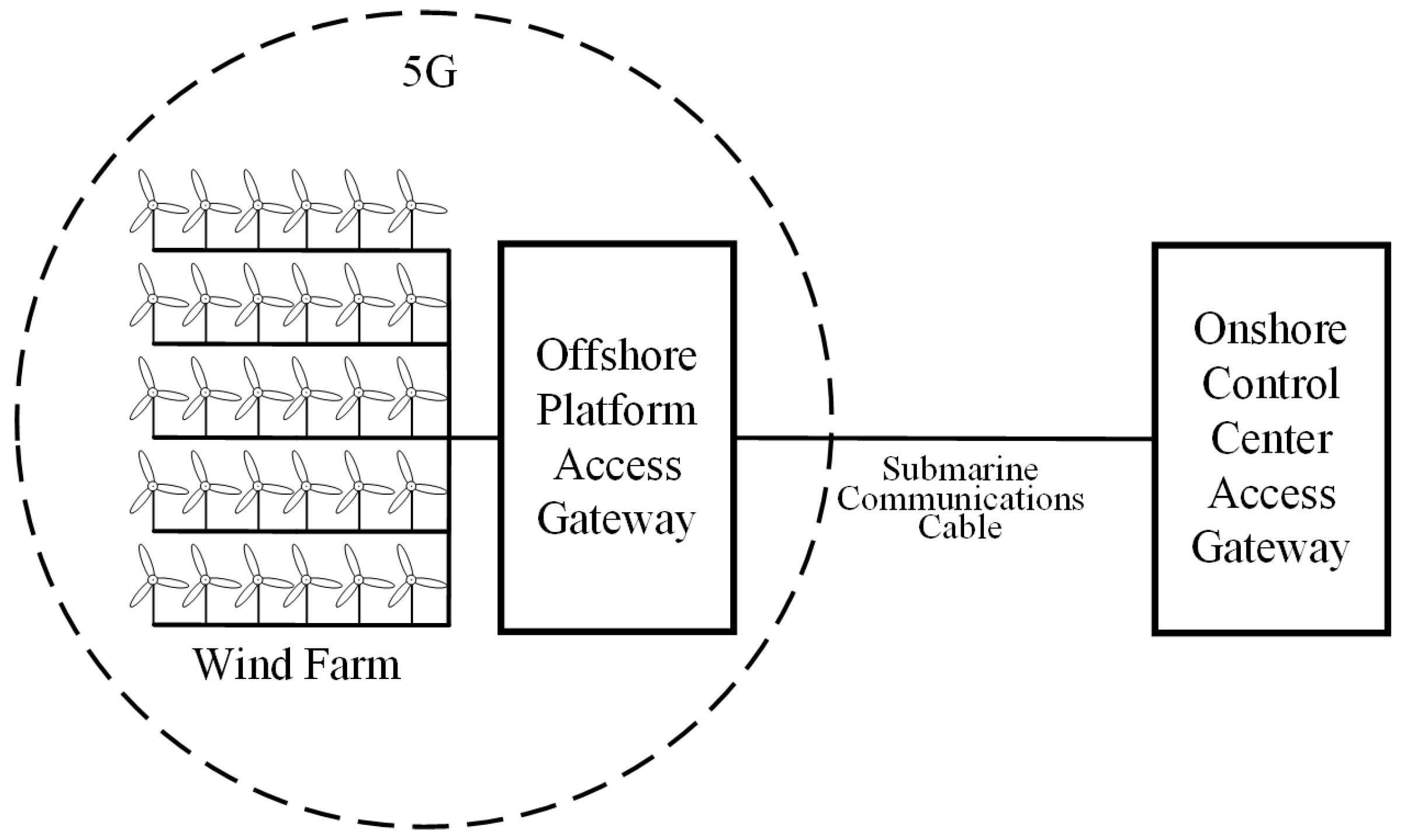
The communication between offshore and onshore converter stations relies on optical fiber communication via composite submarine cables. For the offshore converter station, the communication method employs a hybrid approach combining PTN (Packet Transport Network) and integrated small cells. This configuration ensures high stability, robust environmental adaptability, and multi-service transmission capabilities, fulfilling the functional requirements of offshore wind power communication systems.
The 5G-integrated small cell is a highly compact micro-base station capable of 5G access. By integrating the 5G small cell with the PTN gateway and leveraging broadband PTN access, this system enables efficient and reliable 5G signal coverage. The offshore platform ensures wireless coverage across the wind farm through the PTN network and integrated small cells. Each wind turbine tower is equipped with a small cell, while the A-devices (Access Gateways) on the offshore converter platform and within individual turbines are interconnected via fiber-optic links. The A-devices on the offshore platform transmit data back to those at the onshore control center through optical fiber. The communication architecture for the offshore converter station is depicted in
Figure 4.
To improve the reliability of the communication system, a backup solution using LEO (Low Earth Orbit) satellite communication is implemented as a redundancy mechanism in case of 5G communication failure.
The communication between offshore and onshore converter stations employs optical fiber transmission through composite submarine cables, with a maximum latency of 30 ms. Between the offshore converter station and individual wind turbines, communication is based on 5G technology, forming the offshore wind farm’s communication network through the PTN system and integrated small cells on the converter platform, with a maximum latency of 50 ms. As a backup solution, LEO satellite communication exhibits slightly higher latency compared to 5G communication. Therefore, the communication delay for the offshore AC system is conservatively estimated at 100 ms.
Stage 1 of the black-start process operates without offshore-onshore communication. In Stage 2, after the onshore MMC has established DC-side voltage, the onshore converter station transmits a charging command to the auxiliary MMC via optical fiber communication. Following the successful remote charging of the auxiliary MMC, the onshore station issues a startup command after a 30 ms delay. Upon the offshore MMC startup confirmation, the offshore converter station transmits a startup signal via 5G communication to activate the preselected 0.1 pu wind turbines. After a stabilization period, once these turbines achieve steady-state operation, the offshore station sends a command to reduce their active power output. In Stage 3, after the DC-side switch Bp of the DRU opens, the offshore converter station sends a rated power operation command via 5G to the 0.1 pu wind turbines. In Stage 4, the offshore converter station transmits a signal via optical fiber communication to the onshore converter station, instructing it to raise the DC voltage reference to 1 pu. After acknowledgment from the onshore station, the offshore MMC engages additional DC voltage control. Once the auxiliary transformer is bypassed and the system stability is confirmed, the onshore converter station signals the offshore converter station via optical fiber communication. The offshore station then uses 5G to issue startup commands to the remaining wind turbines, synchronizing them with the offshore AC system.
Based on the above analysis of communication during the black-start process, the proposed black-start method does not impose stringent requirements on communication speed. The system maintains stable operation in all phases where communication is required. In the event of communication system failures during the process, the backup communication approach can still successfully complete the startup procedure.
4. Simulation Verification
4.1. Black-Start Strategy Simulation
To validate the correctness of the proposed black-start strategy, a simulation model of the offshore wind power DC transmission system based on the DRU-MMC series hybrid converter was established in PSCAD/EMTDC. The key parameters are listed in
Table 1. The simulation was conducted in PSCAD/EMTDC 4.6.3 with a time step of 50 μs. In the simulation results and analysis, the positions of each switch are shown in
Figure 1. The valve-side voltage of the onshore MMC is measured between the AC output side of the onshore MMC bridge arm and the connected transformer. The DC-side voltage of the onshore MMC is measured at the DC terminal of the onshore MMC. The DC-side voltage of the offshore MMC is measured at the DC terminal of the offshore MMC. The AC system voltage at the offshore PCC is measured at the connection point between the wind farm and the offshore converter station. The active power of the wind farm is measured at the connection point between the wind farm and the offshore converter station. The DC current is measured at the positive pole of the onshore MMC’s DC terminal. The DC-side voltage of the DRU is measured at its DC terminal. The wind turbine frequency is measured at the connection point between the wind turbine and the offshore AC collection system.
According to the black-start strategy proposed in
Section 3, the simulation is divided into four stages. In the initial stage of a black start, the submodule capacitor voltages of the onshore MMC converter station are zero, and the DC system has no voltage. The DRU AC-side circuit breaker Brk5 remains open, while the DC-side bypass switch Bp is closed. By closing the AC circuit breaker Brk1, the onshore grid begins charging the submodule capacitors in the onshore MMC. Due to the connection of the small-capacity auxiliary transformer, the effective valve-side voltage of the onshore MMC decreases from the rated 220 kV to 80 kV. After the onshore MMC is put into operation, the valve-side voltage rapidly stabilizes. The three-phase valve-side voltage waveforms of the onshore MMC are shown in
Figure 5a. At 2 s, the constant DC voltage control is enabled with a reference value set to 0.25 pu. The DC-side voltage of the onshore MMC is illustrated in
Figure 5b. Since the AC-side valve-side operates at a reduced voltage level, no overmodulation occurs even at this lower DC voltage.
After the onshore MMC is successfully started and stabilized, the system proceeds to Stage 2. At 5 s, the offshore auxiliary MMC begins drawing power from the DC side to charge and boost its DC voltage, as shown in
Figure 6a. At 6 s, the offshore auxiliary MMC activates V/f control with its voltage amplitude command set to a constant 1 pu. The AC voltage at the offshore PCC point rises to near its rated value, illustrated in
Figure 6b. At 6.5 s, a wind turbine with 0.1 pu capacity starts and connects to the offshore AC system, with its output active power shown in
Figure 6c. At 7.5 s, through communication and additional control strategies, the active power output of the wind turbines is reduced to ensure the DC line current remains within the breaking capacity of bypass switch Bp. This guarantees the successful subsequent connection of the DRU, with the corresponding DC current shown in
Figure 6d.
When the active power output of the wind turbine unit drops to a low level, the system enters the third stage. At 11 s, the DC current has decreased to within the breaking capacity of the bypass switch Bp. Subsequently, the AC-side switch Brk5 of the DRU closes, the DC-side switch Bp opens, and the DRU is connected to the system for operation. The DC voltages of the offshore platform auxiliary MMC and the DRU are shown in
Figure 7a. At 11.5 s, communicating with the turbines again to restore the active power output of the connected 0.1 pu wind turbine to its rated value. The variation in wind power active power is illustrated in
Figure 7b.
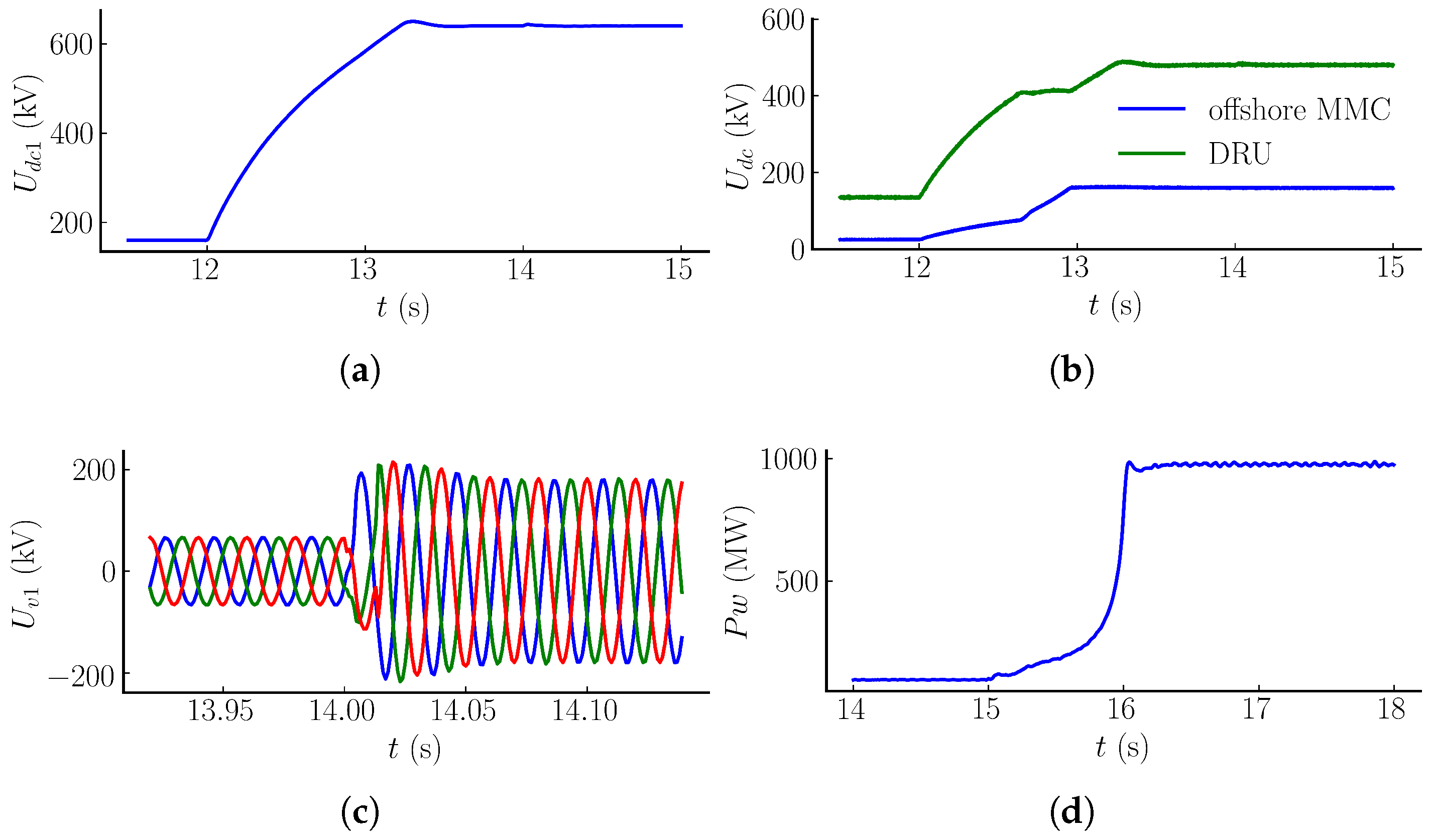
With the DRU officially put into operation, the system enters the fourth stage. At 12 s, the DC voltage reference of the onshore MMC is increased to 1 pu. By absorbing energy from the system, the onshore MMC raises the submodule capacitor voltage, and its DC voltage is shown in
Figure 8a. Simultaneously, the offshore auxiliary MMC engages additional DC voltage control to maintain a constant proportional distribution of DC voltage between the DRU and the auxiliary MMC under steady-state conditions, as illustrated in
Figure 8b. By 14 s, the DC port voltage of the offshore series converter has stabilized. The bypass switch Brk3 closes, Brk2 opens, and the auxiliary step-down transformer on the AC side of the onshore MMC is disconnected. The effective value of the MMC valve-side voltage rises to its rated 220 kV level, with the waveform shown in
Figure 8c. At 15 s, the remaining wind turbines in the wind farm are all started and connected to the offshore AC system. The output power of the wind farm increases to its rated value, as depicted in
Figure 8d. Ultimately, the stable operation of the wind farm is achieved, delivering steady-state rated power.
During the startup process, the phase-locked loop (PLL) frequency waveforms of the wind turbine units exhibit distinct behaviors across different stages. The PLL frequency waveform of the 0.1 pu wind turbine unit activated in Stage 2 is shown in
Figure 9a, while that of the 0.9 pu wind turbine unit activated in Stage 4 is presented in
Figure 9b. The frequency waveforms reveal that when the DRU is connected, the 0.1 pu wind turbine unit in Stage 2 experiences a frequency transient before stabilizing. During the rapid power ramp-up of the wind turbine activated in Stage 4, all wind turbine frequencies undergo minor disturbances, and the frequency variations in the 0.1 pu unit in Stage 2 align with those of the 0.9 pu unit in Stage 4. Throughout the remaining black-start process, the PLL frequencies of the wind turbines remain stable.
The simulation results from the four stages described above demonstrate that the variations in voltage, current, and power remain stable throughout the black-start process. The control strategies implemented during each stage of black-start operate stably and effectively, ensuring successful integration and stable operation of all wind turbines. Furthermore, the system effectively regulates voltage and power variations during different phases of the black-start process.
4.2. Simulation Test of Adaptability to Wind Speed Fluctuations During Black Start
Considering the wind speed fluctuations during the startup process of the wind farm, a black-start simulation was performed. The wind speed waveform is shown in
Figure 10a, while the total active power output of the wind farm is illustrated in
Figure 10b. The DC voltage waveforms of the offshore MMC and DRU are presented in
Figure 10c, and the PLL frequency of the wind turbine is shown in
Figure 10d. The simulation results demonstrate that the system maintains stable operation during startup despite wind speed variations. The proposed black-start strategy maintains system stability under wind speed fluctuations during the initiation process.
4.3. Discussion on the Black-Start Strategy
4.3.1. Synchronization Stability Issues of Wind Turbines
During the startup process in Stage 2, after the offshore auxiliary MMC is activated, V/f control is applied to establish the offshore AC voltage with predefined frequency and amplitude. In the subsequent 0.1 pu wind turbine startup phase, if some wind turbines experience synchronization issues due to failures in their PLL controls or other reasons, their synchronization capability decreases, resulting in fluctuations in both active and reactive currents. This results in oscillations in the d-axis and q-axis current components of the offshore MMC, which propagate to the DC voltage under its control, causing it to oscillate. If a significant number of wind turbines within the 0.1 pu group lose synchronization, prolonged and severe voltage fluctuations will be detected, triggering the AC voltage protection devices across the offshore AC system and ultimately forcing the offshore converter station into a blocked state. Similarly, in Stage 4, during the process of connecting all wind turbines in the wind farm, if a large number of turbines lose synchronization, substantial voltage fluctuations will occur in the offshore AC system. Consequently, the offshore converter station will enter a blocked state, and the AC voltage protection devices in various parts of the offshore AC system will operate.
4.3.2. Black-Start Duration
In practical engineering applications, the phase current amplitude during the charging of the valve side in each converter during the startup process is limited to 50 A by current-limiting resistors. For the onshore MMC and offshore MMC mentioned before, the respective charging times are approximately 10 s and 3 s. Considering the wind farm startup duration, the 0.1 pu wind turbine group requires 1 min for startup, whereas the 0.9 pu group necessitates 9 min. Additionally, a margin of 10 s is added to the control time intervals for each phase of the startup process. As a result, the total black-start duration is approximately 12 min.
4.3.3. Fault Handling and Protection Coordination During Black-Start Process
During the black-start process, the limitations of device voltage withstand capability and current-carrying capacity require that the protection settings for submodule voltage, DC port voltage, and bridge arm current remain consistent with the steady-state design values. In Stage 3 of the proposed black-start strategy, the DC-side switch Bp of the DRU undergoes an opening/closing action, which may cause a certain degree of overvoltage. However, since the total DC voltage of the onshore station during this stage of the black-start strategy is 0.25 pu and the wind turbines operate under low active power control, the DC current level is very low. Consequently, the bypass switch Bp does not induce excessively high DC voltage spikes when opening, as shown in
Figure 7a. After the DRU is connected, the DC voltage is shared between the DRU and the offshore MMC, leading to a rapid decrease in the offshore MMC’s DC voltage. This results in submodule capacitor voltage drops, and the rapid dissipation of the stored capacitor energy. The bridge arm current of the offshore MMC temporarily reaches a relatively high level. This current flows through the DRU and travels from the DC line to the onshore station. Therefore, to limit the magnitude of the offshore MMC bridge arm current, current-limiting resistors can be installed on the DRU’s AC side during integration. In Stage 4, when the onshore MMC increases the DC-side voltage command value to 1 pu, overvoltage risks at various DC ports may arise. To mitigate this, a linear ramp-up is introduced during the adjustment of the command value at the onshore MMC. The voltage command rises gradually from 0.25 pu to 1 pu over a defined period, preventing abrupt changes that could trigger DC-side overvoltage. This approach avoids activating submodule voltage and DC port voltage protections. With the aforementioned method, the protection settings for submodule voltage, DC port voltage, and bridge arm current can maintain their steady-state design values during the black-start process, removing the necessity to relax them during startup. If a fault such as a short circuit occurs during the startup process, the converter can promptly enter a blocked state, while other protection mechanisms in the system can also respond in time, thereby enhancing system reliability.
5. Comparison of Five Black-Start Strategies
Taking the simulation system provided in
Section 4 as an example, an analysis is conducted on five black-start schemes for MMC-DRU series-connected offshore wind power transmission. The comparative results of these black-start schemes are summarized in
Table 2.
For offshore wind farms employing diesel generators as a black-start solution, the initial step involves charging the offshore auxiliary MMC, followed by energizing the wind farm. Considering the startup of a 0.1 pu wind farm, its auxiliary equipment power consumption is 5%, corresponding to 5 MW. The power loss of auxiliary equipment on the offshore converter platform is estimated at 2% of the MMC capacity, corresponding to 8 MW. To account for the surplus power required during charging, this solution employs a 20 MW diesel generator with an approximate cost of 1.5 million USD. Additionally, the increased costs associated with fuel weight and volume on the offshore platform, as well as the rise in operation and maintenance costs due to repeated black-start scenarios under windless conditions, must be considered. This approach is applicable to all wind power projects with offshore platforms and has virtually no technical limitations. Its advantages lie in fewer switching operations, low complexity, and high reliability. Notably, the inverter-side DC voltage maintains stability during startup, which enables flexible black-start sequencing in multi-terminal DC configurations while demonstrating robust scalability.
The cost of utilizing an AC submarine cable from an existing offshore wind power transmission system for a black start depends on the distance between wind farms. This method leverages the existing offshore AC system to provide black-start power for newly constructed wind farms, offering high reliability and low complexity. However, this solution has notable limitations, as it requires the presence of another wind farm in close proximity, making it applicable only in specific projects and resulting in poor scalability.
In the DC-side energy-storage-based black-start solution, the charging time required for the energy storage system to energize the MMC and the wind farm is closely related to the total battery capacity. Considering the auxiliary equipment power consumption of the 0.1 pu wind farm and the need to charge both terminal MMCs and the 0.1 pu wind farm for 10 min, the configuration requires an 0.83 MWh energy storage battery and 300 energy storage submodules. Utilizing 4500 V/1200 A IGBTs, the additional total cost is approximately 1.6 million USD. This solution is highly sensitive to startup time. Increasing reliability by extending the startup duration would lead to higher energy storage capacity and costs. The scheme involves the complex control of the energy storage system and DC switching operations. Moreover, the change in DC voltage during the startup process poses challenges for adaptation to multi-terminal offshore wind integration scenarios.
The onshore hybrid MMC solution requires replacing 50% of the half-bridge submodules with full-bridge modules, necessitating additional 1800 IGBTs rated at 4500 V/3000 A, resulting in a substantial cost increase of 10 million USD. While this approach offers DC fault-clearing capability and high reliability, it requires the coordinated control of DC circuit breakers for DRU switching and low-power operation of the wind farm, resulting in medium-level complexity. The variation in DC voltage at the inverter station during the startup process also limits its applicability in multi-terminal offshore wind integration scenarios.
In the black-start scheme based on a low-capacity auxiliary transformer, the selected auxiliary transformer has a rated capacity of 120 MVA and a voltage ratio of 220 kV/80 kV, requiring an additional cost of approximately 0.55 million USD. This scheme requires the coordination of DC switches with DRU operation and low-power operation of the wind farm, resulting in moderate complexity. During the startup process, considering the 50 ms switching coordination time, switch Brk3 is first closed to bypass the auxiliary transformer. A current-limiting resistor is installed on the bypass branch to reduce the bypass current, followed by opening switch Brk2 to disconnect the auxiliary transformer. Finally, the connected current-limiting resistor is bypassed to reduce converter transmission losses and ensure that the auxiliary transformer disconnection process does not cause thermal faults due to overcurrent. Compared to the hybrid MMC scheme, this approach lacks DC fault-clearing capability, resulting in moderate reliability. It is also affected by DC voltage variations at the inverter station, making it less adaptable to multi-send-end offshore wind grid integration.
6. Conclusions
This paper proposes a four-stage black-start strategy based on the switching of an auxiliary step-down transformer at the AC side of the onshore MMC for an offshore wind power DC transmission system comprising grid-following wind turbines and series-connected DRU-MMC hybrid converters. The additional cost introduced for black-start implementation is limited to installing a small-capacity step-down transformer at the onshore station. This strategy preserves the cost advantage of the DRU architecture while meeting the black-start requirements of wind farms.
The strategy sequentially accomplishes: the pre-charging of the onshore MMC submodule capacitors and low-voltage DC control, the charging of the offshore auxiliary MMC submodule capacitors and AC voltage establishment, the low-active-power control of wind turbines, and DRU integration and transition to rated wind power operation. The simulation results demonstrate that this method maintains system stability during stage transitions and successfully achieves black-start for offshore wind farms.
However, the proposed black-start scheme presented in this paper still has limitations. The method fails to provide inertia support to the power grid during the start-up process due to the inability to achieve fast and effective active power control. Moreover, when faults occur during black-start operations, the converter station must be blocked for fault handling, requiring further research on fault ride-through capabilities during the start-up process. Since the proposed strategy necessitates the onshore converter station to reduce DC voltage during start-up, its application in multi-terminal DC systems or hybrid topologies with other light rectifier stations would require initiating the black-start process with the series topology first. Consequently, this method faces flexibility constraints when extended to multi-terminal systems.
From a stability analysis perspective, this paper only evaluates the strategy’s robustness by introducing wind speed fluctuations during the start-up process, lacking a small-signal analysis of the transition phases between different black-start stages to ensure process stability. Additionally, the validation of the proposed black-start strategy in this study relies solely on PSCAD/EMTDC simulations, without further hardware-in-the-loop (HIL) simulations or physical experiments for more comprehensive verification.
Future research directions may include the following:
Enhance the dynamic response capability of the black-start process by investigating fast active-power-control-based inertia support strategies and developing fault ride-through schemes suitable for the startup phase to improve system robustness against grid disturbances.
For multi-terminal DC application scenarios, explore coordinated black-start methods for DRU-MMC series topologies with other rectifier stations, improving system scalability by optimizing startup sequences or introducing multi-voltage level control.
Deepen the study of stability mechanisms by establishing small-signal models for transition processes at each stage to reveal the influence of key parameters on stability and designing corresponding stability margin optimization strategies.
Construct an HIL test platform or conduct physical experiments to validate the adaptability of strategies, thereby providing more robust practical foundations for engineering applications.
Author Contributions
Conceptualization, F.L. and D.C.; methodology, F.L.; software, H.C.; validation, T.H. and G.W.; formal analysis, S.L.; investigation, Y.H.; resources, H.Y.; writing—original draft preparation, F.L.; writing—review and editing, F.L.; visualization, D.C.; supervision, Y.H.; project administration, F.L.; funding acquisition, Y.H. All authors have read and agreed to the published version of the manuscript.
Funding
This research was funded by the Science and Technology Project of China Southern Power Grid Co., Ltd. (Grant: GDKJXM20231022).
Data Availability Statement
The original contributions presented in this study are included in the article. Further inquiries can be directed to the corresponding author.
Conflicts of Interest
Authors Feng Li, Danqing Chen, Honglin Chen, Shuxin Luo and Hao Yu were employed by the company Grid Planning & Research Center of Guangdong Power Grid Co., Ltd. The remaining authors declare that the research was conducted in the absence of any commercial or financial relationships that could be construed as a potential conflict of interest.
References
- Díaz, H.; Guedes Soares, C. Review of the current status, technology and future trends of offshore wind farms. Ocean Eng. 2020, 209, 107381. [Google Scholar] [CrossRef]
- Zhou, H.; Yao, W.; Zhou, M.; Ai, X.; Wen, J.; Cheng, S. Active Energy Control for Enhancing AC Fault Ride-Through Capability of MMC-HVDC Connected With Offshore Wind Farms. IEEE Trans. Power Syst. 2023, 38, 2705–2718. [Google Scholar] [CrossRef]
- Huang, Y.; Zhang, J.; Wang, G.; Xu, Z. Transient stability analysis and improvement of isolated renewable energy bases with VSC-DC transmission. CSEE J. Power Energy Syst. 2025, 1–11. [Google Scholar] [CrossRef]
- Xu, Z.; Jin, Y.; Zhang, Z.; Huang, Y. Eight Typical Schemes of Offshore Wind Power Transmission and Their Key Technical Problems. Energies 2023, 16, 658. [Google Scholar] [CrossRef]
- Deng, J.; Cheng, F.; Yao, L.; Xu, J.; Mao, B.; Li, X.; Chen, R. A review of system topologies, key operation and control technologies for offshore wind power transmission based on HVDC. IET Gener. Transm. Distrib. 2023, 17, 3345–3363. [Google Scholar] [CrossRef]
- Reidy, A.; Watson, R. Comparison of VSC based HVDC and HVAC Interconnections to a Large Offshore Wind Farm. In Proceedings of the IEEE Power Engineering Society General Meeting, 2005, San Francisco, CA, USA, 12–16 June 2005; pp. 71–78. [Google Scholar] [CrossRef]
- Alassi, A.; Bañales, S.; Ellabban, O.; Adam, G.; MacIver, C. HVDC Transmission: Technology Review, Market Trends and Future Outlook. Renew. Sustain. Energy Rev. 2019, 112, 530–554. [Google Scholar] [CrossRef]
- Martinez-Turegano, J.; Vidal-Albalate, R.; Ano-Villalba, S.; Bernal-Perez, S.; Blasco-Gimenez, R. Protection Strategies for the Connection of Diode Rectifier-Based Wind Power Plants to HVdc Interconnectors. IEEE J. Emerg. Sel. Top. Power Electron. 2021, 9, 7018–7031. [Google Scholar] [CrossRef]
- Yang, B.; Liu, B.; Zhou, H.; Wang, J.; Yao, W.; Wu, S.; Shu, H.; Ren, Y. A critical survey of technologies of large offshore wind farm integration: Summary, advances, and perspectives. Prot. Control Mod. Power Syst. 2022, 7, 17. [Google Scholar] [CrossRef]
- Xiao, H.; Huang, X.; Huang, Y.; Liu, Y. Self-Synchronizing Control and Frequency Response of Offshore Wind Farms Connected to Diode Rectifier Based HVDC System. IEEE Trans. Sustain. Energy 2022, 13, 1681–1692. [Google Scholar] [CrossRef]
- Li, Z.; Song, Q.; An, F.; Zhao, B.; Yu, Z.; Zeng, R. Review on DC transmission systems for integrating large-scale offshore wind farms. Energy Convers. Econ. 2021, 2, 1–14. [Google Scholar] [CrossRef]
- Bidadfar, A.; Saborio-Romano, O.; Cutululis, N.A.; Sorensen, P.E. Control of Offshore Wind Turbines Connected to Diode-Rectifier-Based HVdc Systems. IEEE Trans. Sustain. Energy 2021, 12, 514–523. [Google Scholar] [CrossRef]
- Zhang, Z.; Zhao, X. Startup Control of Grid-Forming Offshore Wind Turbines Connected to the Diode-Rectifier-Based HVDC Link. IEEE Trans. Sustain. Energy 2025, 16, 407–418. [Google Scholar] [CrossRef]
- Zhang, H.; Xiang, W.; Lin, W.; Wen, J. Grid Forming Converters in Renewable Energy Sources Dominated Power Grid: Control Strategy, Stability, Application, and Challenges. J. Mod. Power Syst. Clean Energy 2021, 9, 1239–1256. [Google Scholar] [CrossRef]
- Wu, Y.; Zhang, L.; Zhou, Y.; Hu, Z.; Zhao, X.; Zhuang, Q. A hybrid HVDC converter based on MMC and diode rectifier for offshore wind farm integration. In Proceedings of the 2021 International Conference on Power System Technology (POWERCON), Haikou, China, 10–11 November 2021; pp. 1476–1480. [Google Scholar] [CrossRef]
- Chang, Y.; Cai, X. Hybrid Topology of a Diode-Rectifier-Based HVDC System for Offshore Wind Farms. IEEE J. Emerg. Sel. Top. Power Electron. 2019, 7, 2116–2128. [Google Scholar] [CrossRef]
- Nami, A.; Rodriguez-Amenedo, J.L.; Arnaltes, S.; Alvarez, M.A.C.; Baraciarte, R.A. Hybrid HVDC System for Offshore Wind Farms Connection Using Series-connected Diode Rectifier Units. In Proceedings of the 2019 21st European Conference on Power Electronics and Applications (EPE’19 ECCE Europe), Genova, Italy, 2–6 September 2019; pp. P.1–P.10. [Google Scholar] [CrossRef]
- Fang, Z.; Cai, X.; Shi, X.; Lyu, J.; Yang, R.; Rao, F. Diode rectifier-based hybrid high-voltage direct current converter for offshore wind farms. IET Renew. Power Gener. 2023, 17, 907–919. [Google Scholar] [CrossRef]
- Nguyen, T.H.; Lee, D.C.; Kim, C.-K. A cost-effective converter system for HVDC links integrated with offshore wind farms. In Proceedings of the IECON 2013—39th Annual Conference of the IEEE Industrial Electronics Society, Vienna, Austria, 10–13 November 2013; pp. 7978–7983. [Google Scholar] [CrossRef]
- Cardiel-Álvarez, M.Á.; Nami, A.; Arnaltes, S.; Rodriguez-Amenedo, J.L. Hybrid bipolar VSC-DRU HVdc connection for offshore wind farms. Int. J. Electr. Power Energy Syst. 2023, 151, 109170. [Google Scholar] [CrossRef]
- Chen, L.; Wang, J.; Li, Z.; Guo, C.; Zhang, B.; Li, Z. Steady-State Analysis of the DR-MMC Based Hybrid Topology for Offshore Wind Power Transmission. IEEE Trans. Power Electron. 2025, 40, 3177–3188. [Google Scholar] [CrossRef]
- Li, R.; Yu, L.; Xu, L.; Adam, G.P. Coordinated Control of Parallel DR-HVDC and MMC-HVDC Systems for Offshore Wind Energy Transmission. IEEE J. Emerg. Sel. Top. Power Electron. 2020, 8, 2572–2582. [Google Scholar] [CrossRef]
- Xie, L.; Yao, L.; Cheng, F.; Li, Y.; Liang, S. Coordinate control strategy for stability operation of offshore wind farm integrated with Diode-rectifier HVDC. Glob. Energy Interconnect. 2020, 3, 205–216. [Google Scholar] [CrossRef]
- Wang, Y.; Tang, B.; Chang, Y.; Wang, C.; Li, Z. Black-Start and Frequency Response Control Strategies for Offshore Wind Power Transmitted by DR-MMC Series-Connected HVDC System. In Proceedings of the 2024 9th Asia Conference on Power and Electrical Engineering (ACPEE), Shanghai, China, 11–13 April 2024; pp. 2640–2646. [Google Scholar] [CrossRef]
- Wang, Z.; Wang, J.; Zhao, Z.; Li, T.; Sheng, J. Black Start-Up Strategy of MMC in Series with Diode Rectifier Converter for Offshore Wind Farms. In Proceedings of the 2023 IEEE 2nd International Power Electronics and Application Symposium (PEAS), Guangzhou, China, 10–13 November 2023; pp. 570–575. [Google Scholar] [CrossRef]
- Baran, M.E.; Mahajan, N.R. Overcurrent Protection on Voltage-Source-Converter-Based Multiterminal DC Distribution Systems. IEEE Trans. Power Deliv. 2007, 22, 406–412. [Google Scholar] [CrossRef]
- Dogra, R.; Rajpurohit, B.S.; Tummuru, N.R.; Marinova, I.; Mateev, V. Fault Detection Scheme for Grid-connected PV based Multi-terminal DC Microgrid. In Proceedings of the 2020 21st National Power Systems Conference (NPSC), Gandhinagar, India, 17–19 December 2020; pp. 1–6. [Google Scholar] [CrossRef]
| Disclaimer/Publisher’s Note: The statements, opinions and data contained in all publications are solely those of the individual author(s) and contributor(s) and not of MDPI and/or the editor(s). MDPI and/or the editor(s) disclaim responsibility for any injury to people or property resulting from any ideas, methods, instructions or products referred to in the content. |
© 2025 by the authors. Licensee MDPI, Basel, Switzerland. This article is an open access article distributed under the terms and conditions of the Creative Commons Attribution (CC BY) license (https://creativecommons.org/licenses/by/4.0/).


