Article

Hop-by-Hop Multipath Overlay Routing for Optimizing Network Resource Allocation in WANs

1
National Network New Media Engineering Research Center, Institute of Acoustics, Chinese Academy of Sciences, Beijing 100190, China
2
School of Electronic, Electrical and Communication Engineering, University of Chinese Academy of Sciences, Beijing 100049, China
*
Author to whom correspondence should be addressed.
Electronics 2025, 14(13), 2542; https://doi.org/10.3390/electronics14132542
Submission received: 29 May 2025 / Revised: 20 June 2025 / Accepted: 22 June 2025 / Published: 23 June 2025
(This article belongs to the Section Networks)

Abstract

The widespread deployment and rapid expansion of data centers have intensified the traffic between data centers and users, which highlights the need to improve Wide Area Network (WAN) link utilization. Existing centralized traffic control methods based on Software-Defined Wide Area Networks(SD-WAN) often rely on source-based routing, resulting in limited path diversity and inefficient network resource allocation. To address these issues, we propose a hop-by-hop multipath routing method for overlay networks, leveraging the routing decision-making capabilities of intermediate nodes. First, we introduce a Multipath Overlay node Placement (MOP) algorithm to establish an overlay network for hop-by-hop multipath transmission. The spatial relationships among overlay nodes are considered to enhance the diversity of multi-hop multipath overlay routing. Next, we propose an Overlay Next-Hop Selection (ONHS) algorithm for intermediate overlay nodes. This algorithm adjusts transmission paths at intermediate overlay nodes by sensing the network congestion state of overlay tunnels, enhancing the efficiency of network resource utilization. The results demonstrate that, under various topologies and with different numbers of overlay nodes, MOP significantly improves both end-to-end path diversity and link utilization for hop-by-hop multipath transmission. Additionally, ONHS effectively mitigates congestion escalation during next-hop selection.

1. Introduction

The rapid advancement of technologies such as AI and big data analytics is driving the expansion of data centers worldwide [1]. The increase in data centers has intensified the traffic across the wide area networks (WANs), which connect the vast storage and computing capacities in data centers to users and service providers. The features of this traffic are large volume, long distance, and delay requirements. Thus, the efficient utilization of network resources in WANs has become critical. One solution is the use of overlay networks [2]. It is built on top of a legacy network, and can re-route traffic with overlay routing decisions generally made by centralized controllers. Existing overlay solutions are mostly implemented with SD-WANs [3] and built on private clouds, leading to limitations in scalability and flexibility. To overcome this problem, we propose to leverage overlay networks as a public infrastructure that efficiently allocates network resources to all users. The primary challenge is ensuring scalability in overlay routing while optimizing all-to-all transmission performance.
Existing overlay routing solutions predominantly rely on source-based routing, which utilizes pre-determined paths with multiprotocol label switching (MPLS) [4] or segment routing [5]. As the network scale increases, the number of paths grows exponentially, which expands the computational complexity and control cycles of the centralized resource allocation. While an intermediate overlay node can dynamically re-route packets, source-based routing limits routing decisions to the network edges. In contrast, hop-by-hop multipath routing offers multiple next-hop options for each destination, and avoids loops through Loop Free Invariant (LFI) [6] or directed acyclic graphs (DAGs) [7]. This method allows dynamic path switching at intermediate nodes and provides a design space for large-scale overlay routing. However, in the overlay network, tunnels can share overlapped underlay links, which diminishes the performance gain of switching next hops. We tackle this problem from the perspective of overlay node placement and path selection.
The placement of overlay nodes is determined by the service requirements. For all-to-all multipath transmission, nodes are chosen either by minimizing single-hop path overlap [8], maximizing the throughput region [9]. For specific transmissions pairs [10,11,12], overlay nodes are selected based on network topology to ensure that the number of paths meets predefined criteria. These methods are aligned with source-based or single-hop overlay routing. In multi-hop overlay routing, all-to-all routing performance needs to be considered to enable optimal hop-by-hop routing. In order to generate paths with minimal overlap [10], it is necessary to increase the path diversity between any two overlay nodes by leveraging the max-flow min-cut theorem. This study improves the path diversity by increasing the number of utilized underlay links and reducing the overlap among overlay tunnels.
Next-hop selection determines the end-to-end paths of multipath routing. Elastic data flows in the network are capable of dynamically adjusting the transmission rates in response to the available network resources [13]. Compared with the fixed selection of paths in source-based routing, the selection of end-to-end paths grows exponentially with the number of traversed intermediate nodes in hop-by-hop routing. Due to the overhead of tracking end-to-end paths at intermediate nodes, flow information is not recorded and flows are divided into smaller units (flowlets [14], etc). When congestion occurs, flows switch to paths with lower congestion levels and gradually saturate all the available paths. This enables elastic allocation of network resources. However, there are obstacles in this process. On the one hand, the overlap of underlay paths reduces the potential transmission gain from path switching. On the other hand, the limited decision-making information at intermediate overlay nodes makes it difficult to identify globally optimal paths.
This study investigates a hop-by-hop multipath transmission scheme for an overlay network. Building on the existing hop-by-hop multipath routing algorithm, this study mainly focuses on the unique challenges in the overlay network. To alleviate the impact of path overlap on overlay transmission, we propose a multipath overlay node placement (MOP) algorithm and an overlay next-hop selection (ONHS) algorithm. The novelty and strengths of the proposed MOP and ONHS algorithms are as follows:
  • MOP is designed to improve the path diversity in overlay node placement. Existing methods are based solely on single-hop and multi-hop overlay routing, serving only specific transmission node pairs. Instead, MOP focuses on the path diversity of each overlay and provides richer path selection for all-to-all transmission.
  • ONHS introduces a next-hop selection mechanism at the intermediate node. Unlike existing state-of-the-art methods that adopt source-based path selection, dynamic path selection at intermediate nodes not only provides a higher transmission bottleneck, but also responds in real time to the emerging congestion/failure.
In the construction of the overlay network, MOP is developed to increase all-to-all path diversity for hop-by-hop multipath transmission. After performing the static multipath routing algorithm, ONHS efficiently selects the next hop in case of congestion. In short, the contributions of this study are as follows.
  • We propose a hop-by-hop overlay multipath routing method designed for WANS. Building on existing hop-by-hop multipath routing, this method improves transmission efficiency by enhancing path diversity, reducing path overlap, and efficiently utilizing link resources.
  • We introduce MOP, an overlay node placement algorithm that supports hop-by-hop overlay multipath routing. MOP employs a heuristic strategy to enhance both hop-by-hop path diversity and underlay link utilization, thereby improving the performance of all-to-all multipath transmissions. The experiment results demonstrate that MOP consistently improves both end-to-end path diversity and link utilization across different topologies and varying numbers of overlay nodes.
  • We introduce ONHS, a next-hop selection algorithm for overlay multipath routing. ONHS incorporates a local next-hop selection mechanism at intermediate overlay nodes and a global selection strategy for multi-hop routing. The method enhances multipath routing by avoiding the delivery of traffic to congested tunnels. The experimental results show that ONHS reduces the escalation of congestion by at least 20% across various network topologies.
The rest of the paper is structured as follows. Section 2 reviews the related work of this research from the perspective of overlay node placement and overlay multipath routing. Section 3 elaborates on the design of MOP and ONHS, and the implementation of the hop-by-hop multipath routing in the overlay network. Section 4 evaluates the performance of the proposed algorithm. Finally, Section 5 concludes this study.

2. Related Works

2.1. Overlay Node Placement

The overlay nodes can re-route traffic on alternative paths to avoid congestion or failures. The selection of overlay nodes affects the performance of an overlay network. Reference [8] proposed the topology-aware node placement heuristics. The method classifies nodes with similar path diversity and latency into clusters through network measurements. The overlay nodes in a single ISP are randomly selected from every cluster, while the overlay nodes across multiple ISPs are also studied to maximize topology diversity between ISPs. Although the measurement-based method is simple to deploy, it only considers single-hop overlay routing. Reference [10] introduced a genetic algorithm (GA) that maximizes path diversity while minimizing the number of relays. This method defines the end-to-end path diversity of source-destination pairs and optimizes the network implementation by maximizing the minimum path diversity. The path diversity defined in this method is based on end-to-end paths, which lack scalability. Reference [12] defines the Overlay Routing Resource Allocation (ORRA) problem, which selects the minimum number of overlay nodes to meet confined transmission costs. Ref. [9] proposed an overlay node placement algorithm based on the shortest path tree, which can cover all the underlay paths with the minimum number of nodes. While this method can utilize all the underlay links, it does not consider link overlap in multipath transmission, and only fits source-based routing methods. Another approach to network node placement is based on centrality, which does not consider routing characteristics and path overlap [15].
In this study, overlay nodes not only record routing information and perform traffic weight distribution, but also make routing decisions. Moreover, instead of serving specific transmission pairs, this study addresses a more general scenario, all-to-all multipath transmission. This requires considering the positional relationships between all nodes, rather than between specific node pairs.

2.2. Overlay Multipath Routing

Multipath routing improves transmission throughput and reliability by obtaining multiple paths between transmission pairs. It can be categorized into two types: source-based and hop-by-hop. The source-based approach is widely used in SD-WAN scenarios. A centralized controller collects the network information and computes the transmission paths, with the endpoints routing the transmission paths in the packets via MPLS [4] or SRv6 [5]. Based on the concept of routing on disjoint paths, RB-trees [16] generate two independent trees for each destination. SPDP [17] improves the performance by reducing path stretch while generating disjoint paths. These methods only support source-selectable routing, in which the source chooses the routes from pre-calculated paths. To improve scalability, deflection routing [18] provides each router with a set of alternate next-hops and ensures loop-free paths. Path splicing [19] further lowers the cost of routing by introducing multiple routing trees. Each router can flexibly change the routing trees to form multipath, but lacks a mechanism to prevent routing loops. Ref. [20] computes multiple fully disjoint trees while maintaining efficiency and scalability. These methods give the selection of the best path a global perspective, making it suitable for large-scale data transmission. However, it has shortcomings such as long control cycles and limited scalability. Hop-by-hop multipath routing primarily obtains transmission paths by deploying distributed algorithms on network nodes. Since common network devices only support OSPF and IS-IS protocols, the application of such algorithms is not widespread in WANs. In the distributed routing protocol LISP [21,22], nodes can change transmission paths based on the current congestion status and register the path information in a centralized mapping system. The endpoint nodes determine the transmission path by querying the mapping system. However, this approach still requires a registration query process and does not achieve full distribution. A common method is to assign priorities to different next hops [23]. Since overlay nodes are capable of measuring load, Ref. [13] introduces a semi-distributed method. The centralized controller generates transmission paths elastically based on network traffic, and intermediate nodes make routing decisions in response to congestion events. Since overlay nodes support more functionalities, this study intends to implement hop-by-hop multipath routing based on overlay nodes to enhance the scalability of multipath routing. The reference [24] estimates the underlay queue backlogs through a centralized approach to determine the optimal transmission strategy for overlay nodes and proves it to be throughput-optimal.
Most existing overlay routing is source-based routing, which adopts topology planning in determining the efficiency and cost of the overlay networks. Resilient overlay networks (RON) [25] adopt a link-state routing protocol with short-interval probes, which causes a lack of scalability. Ref. [8] proposed a topology-aware overlay network that improves performance of end-to-end communications by leveraging path redundancy and maximizing path independence. Ref. [26] focused on designing overlay topologies by minimizing both overlay link creation costs and routing costs. Ref. [27] developed a minimal-cost communication network topology that adheres to predefined reliability constraints. Reference [28] proposed a method for dynamically configuring the topology based on service requirements. In [28], path overlap can be detected in both known and unknown underlay topologies. To introduce hop-by-hop multipath routing in an overlay network, an important issue is the overlap of underlay paths. While most existing methods rely on a global perspective, this study proposes a hop-by-hop multipath routing approach that avoids path overlap by incorporating both global and local perspectives.

3. System Design

The goal of this study is to establish an overlay network that supports all-to-all hop-by-hop multipath transmission. In this network, the underlay network performs shortest-path routing, while the overlay network performs hop-by-hop multipath routing. To ensure the performance of overlay multipath transmission, two key principles are employed in the design.
  • Maximized path diversity and underlying links utilization.
    During the routing process, it is essential to fully utilize multiple paths to bypass potential transmission bottlenecks. This requires minimizing the overlap of end-to-end paths and maximizing the use of underlying links. The metric is commonly found in classic algorithms related to overlay node placement [8,10,12] and multipath routing [16]. Maximized path diversity and underlying link utilization imply that end-to-end transmission experiences smaller transmission bottlenecks and higher resilience.
  • Cost-effective intermediate node path switching
    Intermediate nodes can flexibly switch paths when congestion occurs. In path switching, the next-hop node with the lowest cost and congestion relief is prioritized, avoiding unnecessary and excessive detours. This metric frequently appears in multipath routing algorithms, such as k-shortest paths and centralized path selection [13]. Achieving transmission with lower costs means the efficient utilization of network resources.
The construction of the overlay network in this study involves the following steps. First, overlay nodes are selected from the underlay network, which serve as user access points and perform hop-by-hop multipath transmission. The placement of overlay nodes ensures path diversity for all-to-all transmissions. Second, an existing hop-by-hop multipath routing algorithm (LFI, MARA) is performed on the overlay topology based on the cost of tunnels. The cost is determined by the propagation delay and capacity of tunnels. It generates the next hop set for each intermediate node and ensures loop-free transmission. Third, overlay nodes periodically assess the load of tunnels to their adjacent nodes, and selectively choose the next-hops to mitigate the occurrence of unnecessary or excessive detours. Figure 1 illustrates the structure of the network. In the underlay layer, solid nodes represent standard network routing devices that support only shortest-path routing, while hollow nodes represent overlay nodes that support overlay-based multipath routing proposed in this paper. Overlay nodes are fully connected and capable of perceiving the status information of the overlay layer. The status and routing rules of the overlay layer nodes can be managed and maintained through the controller.
In the overlay hop-by-hop multipath routing process, each intermediate node keeps a routing table with multiple next hops for each destination. Periodically, the selection of the next-hop node is narrowed based on the load of each tunnel. For example, Table 1 presents a routing table of the overlay network in Figure 1. The routing table includes the next-hop sets of every overlay node destined to node E, along with the cost and current load of each next-hop. For Node A, the shortest path to Node E is (A,C,E). When the load of tunnel (A,C) indicates that congestion occurs in its underlay links, the next hop of node A is adjusted to Node B and Node D. Node B has a lower cost than Node D, making it prioritized in the path selection. When the load of tunnel (C,E) indicates that congestion occurs in its underlay links, the next hop of node B is limited to Node D. The details of the overlay multipath transmission process are as follows:
1.
The controller generates the next-hop set for each overlay node based on existing hop-by-hop multipath algorithms.
2.
At regular time intervals, the controller adjusts the original next-hop set of each overlay node based on the load conditions of all tunnels.
3.
During transmission, when a data packet arrives, the overlay node selects the next hop based on the destination of the packet. It chooses the lowest-cost, non-congested node from its multipath next-hop set.
Table 2 summarizes the mathematical symbols in this paper. The rest of the section is structured as follows. Section 3.1 illustrates the overlay node placement algorithm, Section 3.2 explains the next hop selection algorithm for hop-by-hop multipath routing in the overlay network, and Section 3.3 introduces the implementation of the hop-by-hop overlay multipath routing algorithm.

3.1. Overlay Node Placement

The underlay network is represented as G ( V , E ) , where V is the set of underlay routers and E is the set of underlay edges. Assume that the cost of each link e E is assigned with its latency and capacity, and the graph is connected. The overlay network is layered on top of the existing underlay network. Compared with traditional IP nodes, overlay nodes are capable of dynamically switching the next-hop overlay node, detecting local congestion, and functioning as access points for users and service providers. The goal of overlay node placement is to select a subset from the underlay node set V, and replace it with overlay nodes. Overlay nodes communicate through tunnels. Based on the adjacency relationships between nodes, an overlay topology can be constructed. The cost of constructing the overlay network is influenced by the number of deployed overlay nodes. Consequently, previous studies search for the minimum number of overlay nodes to meet the transmission requirements. In this study, the overlay network performs flexible hop-by-hop routing to meet all-to-all (rather than specific) transmission demands. Therefore, we assume that m overlay nodes are implemented to maximize the performance of multipath transmission on the overlay network. Theoretically, as the number of nodes increases, the benefit of multipath routing improves until it reaches an optimal point.
The placement of the overlay nodes influences the performance and efficiency of the overlay network. According to the max-flow min-cut theorem, the end-to-end maximum bandwidth is equal to the transmission bottlenecks, which are determined by the number of disjoint paths. Overlay routing can utilize multiple disjoint underlying paths, thus improving the transmission bandwidth and reliability. In order to reduce path overlap in overlay multipath routing and increase the utilization of underlying paths, we analyze the characteristics of the hop-by-hop multipath.
As the underlay network employs the shortest path routing algorithm, the underlying links used by an overlay network are the shortest path tree between the overlay nodes. Overlay nodes can alter the next-hop in hop-by-hop multipath routing, utilizing underlay links that are not in the shortest path tree rooted at the destination. By bypassing congested or failed paths, multipath routing enhances the overall transmission efficiency. As shown in Figure 2, on the shortest path tree with the destination node as d s t , each node can follow the shortest path to reach the destination. Node A, as an overlay node, can dynamically switch to the next hop overlay nodes B, C, D, or E, with Node B as shortest path and C, D, E as backup. However, if tunnel (A, C), (A, D), or (A, E) overlap with tunnel (A, B) (as shown in Figure 2b), the congestion in tunnel (A, B) cannot be completely bypassed, resulting in a transmission bottleneck. When overlay node A is replaced by node F, the overlap between tunnel (F, C), (F, D), (F, E) and (F, B) is reduced (as shown in Figure 2c), making it a better choice for node placement. In order to improve the overall ability to bypass congested or failed paths, the overlap of the next-hop of each overlay node is considered.
Another factor is the occupation of the underlay links. Based on the research in literature [
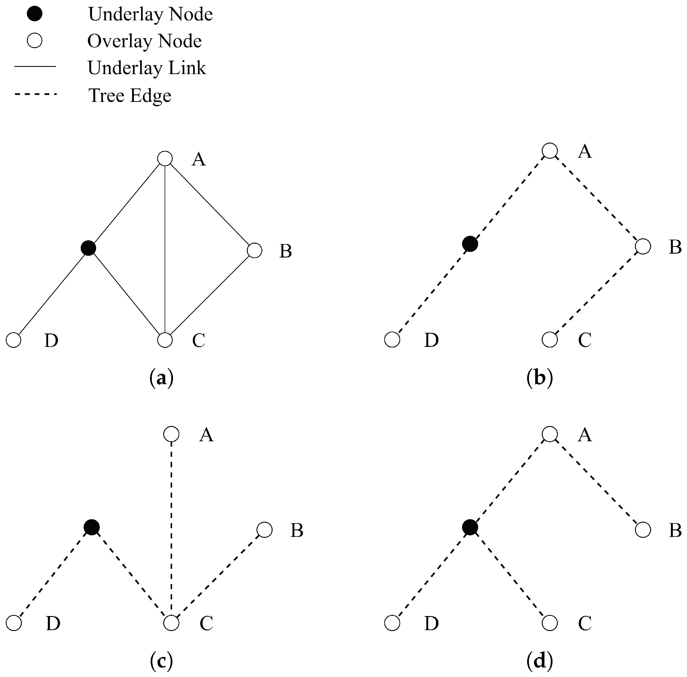
9], we observe that the underlying links occupied by the overlay network are formed by a concatenation of shortest path trees with the overlay nodes as roots and their neighboring nodes as leaves. Obviously, gaining access to a larger number of underlay paths through a small number of overlay nodes can enhance the efficiency and potentially diversify the paths of overlay multipath routing. Figure 3 illustrates an example of underlay link utilization. Figure 3a shows the complete topology, while Figure 3b–d represents the underlay links occupied by overlay nodes B, C, and D to their neighboring overlay nodes, respectively.
However, we find that these two metrics are not consistent. To reduce path overlap, nodes with high centrality are more likely to appear in the transmission path, which helps to decrease path overlap (as shown in Figure 2). On the other hand, to increase the diversity of underlay paths, it is preferable to choose nodes where there is a discrepancy between the degree of the shortest path tree and the degree of the graph. (as shown in Figure 3). To describe the ability of overlay nodes to bypass congested or failed paths, we study hop-by-hop path diversity d n for overlay node n. We define the underlay link utilized by the shortest paths of the overlay tunnel between node x and y as
l ( x , y ) = { l | l shortest underlay paths between x and y }
Assuming the set of neighboring overlay nodes for node n is denoted as S n , the set of underlay paths occupied by node x and its neighbors is defined as
U n = s S n l ( s , n )
The overlap of the tunnel ( n , m ) with the tunnel between the node n and its other neighbor node is defined as
Overlap ( n , m ) = l ( n , s ) s S n { m } l ( s , n ) l ( n , s )
The hop-by-hop path diversity d n of overlay node n is defined as the sum of independent paths, which can be calculated by Algorithm 1. The ultimate goal of enhancing d n of overlay nodes is to increase the end-to-end path diversity for all-to-all multipath transmission. The end-to-end path diversity D ( x , y ) is defined as the total number of independent paths obtained from hop-by-hop multipath routing. We believe that the local path diversity of overlay nodes determines the end-to-end transmission path diversity in the network.   
Algorithm 1: Path Diversity Calculation
Electronics 14 02542 i001
Theorem 1. 
The number of overlay nodes is m. If  n = 0 m d n reaches the maximum, then the path diversity of all-to-all end-to-end transmissions also reaches its maximum.
Proof of Theorem 1. 
Assume the contrary, that n = 0 m d n does not reach its maximum, implying that the end-to-end path diversity is not maximized. If  d n is not maximized for some node n, it indicates that there are redundant or insufficient independent paths between node n and its neighbors. Thus, the set of underlay paths U n , occupied by node n and its neighbors, will also be suboptimal. This results in a decrease in the total path diversity of the network. A reduction in d n leads to fewer independent paths, which in turn reduces the end-to-end path diversity.
Therefore, if  n = 0 m d n does not reach its maximum, the end-to-end path diversity cannot be maximized, leading to a contradiction. Hence, if  n = 0 m d n reaches its maximum, the end-to-end path diversity of all overlay transmissions must also reach its maximum.   □
In addition to the path diversity between overlay nodes, user access should also be considered. Clustering of overlay nodes leads to inefficiency in serving a large number of underlay users. This study measures the scale of the overlay multipath service by the number of utilized underlay links, with fewer links indicating a higher concentration of overlay nodes. Let N be the set of selected overlay nodes. The multipath overlay node placement (MOP) problem is formulated as follows:
a r g m a x N n N ( d n + α U n )
s . t . N = m
In the above optimization problem, the first term maximizes the overall path diversity in the overlay network. The second term introduces the number of underlying links to promote sparsity in the selected nodes. α is the coefficient of U n , which determines the weight of link utilization and path diversity in the objective function. The constraint (4) limits the number of overlay nodes. In practice, the locations of some service-providing nodes, such as data centers, are predetermined. In such cases, the positions of the rest nodes are calculated based on fixed location of predetermined nodes in the optimization problem.
The problem can be reduced to the Maximum Coverage Problem [29], which has been proven to be NP-hard. To obtain a near-optimal solution in a reasonable time frame, this study adopts a genetic algorithm [30] to solve the above problem. In each generation, the next population is obtained through crossover and mutation, ultimately resulting in an optimal combination of overlay nodes. The complexity of this algorithm primarily depends on the population size P, the overlay node number L, and the number of generations G. The overall time complexity is O ( G · P · L ) and the space complexity is O ( P · L ) .
The overlay node placement problem discussed above aims to maximize overall benefit with a fixed number of nodes. In practice, however, there are scenarios in which the number of overlay nodes is chosen based on the average benefits of the overlay nodes or other specific optimization objective [9]. In the context of this study, the objective is to maximize the path diversity of overlay hop-by-hop multipath routing. Define the objective function
F ( N ) = n N ( d n + α U n )
In the MOP problem described above, once the number of overlay nodes m exceeds a certain threshold, additional nodes contribute only marginal improvements to multipath transmission performance. For both underlay link utilization and overall hop-by-hop path diversity, the marginal gains diminish as m increases, suggesting that the first derivatives of these metrics with respect to the number of overlay nodes exhibit convexity. However, when underlay link utilization and hop-by-hop path diversity are combined into a single objective function F ( N ) , differences in their respective growth behaviors may lead to the presence of local optima. To assess the effectiveness of increasing the number of overlay nodes, we define the optimal number as the smallest value of m for which the marginal improvement falls below a predefined threshold ϵ , i.e.,
d F ( m ) d m > ϵ .
Given that the selection of N is topology-dependent and cannot be expressed analytically, the optimal number of overlay nodes is determined via a search-based method. Let i denote the step size for incrementing the number of overlay nodes. The MOP algorithm evaluates F at each interval, and the derivative is approximated using the finite difference:
β = F ( x ) F ( x i ) i .
When β = ϵ , the corresponding value x is selected as the optimal number of overlay nodes. If two candidate values of x satisfy the condition, the larger (right-hand side) value is chosen to ensure sufficient coverage of performance gains.

3.2. Overlay Hop-by-Hop Routing

To address the congestion issues caused by large-scale data transfers and increase the efficiency of the network layer, we propose a best-effort approach where both load and cost are taken into account. In the hop-by-hop multipath routing algorithm, the cost of the tunnels is determined by latency, which is assumed to be relatively stable. Intermediate nodes can flexibly adjust paths by switching to an alternative next hop. During path selection, tunnels with lower costs are prioritized to reduce transmission costs. When congestion or failures occur, intermediate overlay nodes switch to paths with higher costs but a lower degree of congestion. The existing hop-by-hop multipath routing schemes ensure transmission reachability through LFI or DAG. In overlay networks, tunnels with different endpoints may have overlapping underlay links, which fail to bypass transmission bottlenecks.
In the previous section, the overlay node placement method partially reduces path overlap by maximizing the path diversity of overlay nodes. However, path overlap cannot be eliminated with a limited number of overlay nodes. Path overlap in dynamic multipath routing can easily lead to a decrease in transmission efficiency. Examples are illustrated in Figure 4. A flow from source node A to destination node F has two paths: (A, B, C, F) and (A, B, D, E, C, F). Node A has node F and node D as its next hops. In the next hop selection, tunnel (A, F) and tunnel (A, D) overlap at the underlay link (A, B). The tunnel with the lower cost is (A, F). If link (A, B) is congested, switching the path to (A, D) cannot alleviate congestion. However, if link (B, C) becomes the bottleneck, tunnel (A, D) can bypass congestion. Another scenario involves multi-hop path selection. In this case, the link (C, F) is congested. Although tunnel (A, D) is not congested, switching paths is unable to alleviate congestion while degrading the performance.
We address the issue by measuring the load of the adjacent tunnels at every overlay node. The Discounting Rate Estimator (DRE) [31] is a low-overhead measurement method for high-speed traffic, which is widely applied in data center networks and wide-area networks. It maintains a register that increases with the arrival of each packet and periodically (every T) decreases according to a factor α . The value of the register is proportional to the transmission rate, with a coefficient of T / α . In the following discussion, it is assumed that the tunnel load is obtained through DRE and represented in a normalized form.
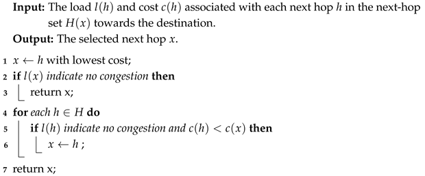
During the routing, if the load of path (A, F) is heavier than the load of path (A, D, E, F), it means that two paths do not share the bottlenecks and path (A, D, E, F) is an alternative path. If both tunnel (A, F) and tunnel (A,D) are overloaded, congestion occurs at the overlapping link (A, B) and switching paths to (A, D) is invalid. And when the tunnel (A, D) is not overloaded, it is unclear whether the link (B, C) or link (C, F) is congested. Algorithm 2 presents the single-hop path selection Algorithm. The algorithm makes decisions at each node based on local load information, selecting non-congested nodes with the lowest cost from the next-hop set.   
Algorithm 2: Single-hop path selection
Electronics 14 02542 i002
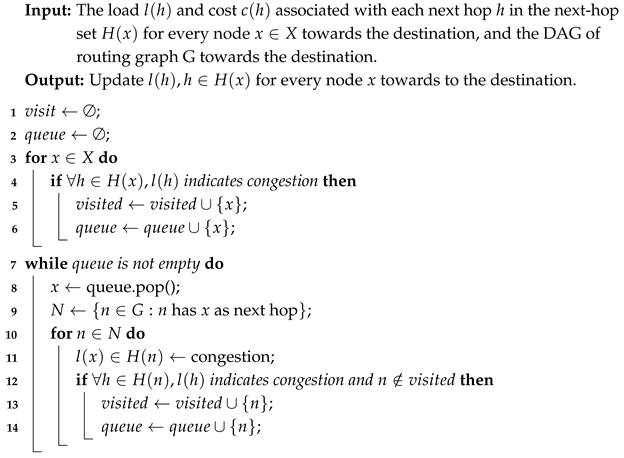
While single-hop congestion is easy to identify, multi-hop path selection needs global coordination. The goal of multi-hop path selection is to avoid transmitting data to congested areas and to filter the paths that cannot bypass congestion. During this process, network resources are effectively allocated to transmissions that are unlikely to cause congestion. This method determines congestion based on the load of the links and removes the next hops that lead to unavoidable bottlenecks. The load information of the tunnel is periodically uploaded to the controller, and the controller updates the next-hop selection results based on the calculated data by Algorithm 3. The excluded next-hops are marked as congested. According to the approach in Algorithm 2, congested next hops have lower priority, which leads data towards non-congested paths and helps to effectively allocate network resources. The complexity of the algorithm for each destination is O ( m + k ) , and the complexity for all-to-all transmission is O ( m ( m + k ) ) , where m is the number of overlay nodes and k is the number of overlay tunnels.
We place the centralized controller at the location closest on average to all nodes. This controller periodically gathers load information of the tunnel from the network. The control delay introduced by this periodic data collection is minimal. Firstly, the periodic approach allows the system to distribute control operations over time, reducing the need for constant adjustments and thereby minimizing latency. Secondly, by strategically positioning the controller near the average center of all nodes, communication latency is further reduced. Furthermore, as observed from the experiments, the impact of Algorithm 3 on the number of paths is significantly smaller than that of Algorithm 2. Therefore, we believe that implementing Algorithm 3 on a centralized controller using a periodic method is appropriate.
Algorithm 3: Multi-hop path selection
Electronics 14 02542 i003

3.3. Resilience in Overlay Routing

Although this study primarily focuses on addressing the congestion issues caused by large-scale data transmission, as it focuses on overlay multipath routing, it also provides resilience against link and node failures. We discuss this from the perspective of overlay node placement and multipath routing.
For Overlay node placement, research on resilience typically aims to find multiple paths that do not share overlapped links/nodes. In this study, the definition of path diversity in node placement is closer to the link overlapped scenario. As the number of independent paths increases, the intermediate node can switch paths to avoid disruptions in the event of a link failure. The definition of path diversity can easily be extended to link overlapped scenarios. Therefore, we believe that the overlay node placement algorithm MOP can also improve the resilience of WAN.
As the overlay routing in this study is based on existing multipath algorithms, it can also support multipath algorithms like red-black trees and SPDP, which can obtain completely non-overlapping paths for resilience. Compared with the limited non-overlapping paths maintained at the edge, this study utilizes intermediate nodes to maintain a greater number of non-overlapping paths and to immediately respond to link/node failures by switching the next-hop node. For overlay routing, we believe that failures are a subset of congestion issues. When the failure of the link/node is detected, it can also be bypassed by changing the next hops.

3.4. Implementation

The overlay hop-by-hop multipath routing is achieved by embedding both the next-hop address and the destination address in the packet header. This approach can be implemented using VXLAN [32], and is also compatible with standard IPv6 protocols [33]. For the IPv6 protocol, we can fill the next-hop address into the destination address field, and place the actual destination address in the IPv6 extension header. At each overlay node, when receiving a packet, if the next-hop address matches itself, it will search for the next hop with the destination address, and change the next-hop address with the result. The workflow of processing packets at the overlay nodes is illustrated in Figure 5. In the underlay network, each router performs shortest-path routing with the next hop locator as the destination. Figure 6 illustrates the relationship of packet fields and the overlay routing information during the overlay hop-by-hop multipath transmission. At each overlay node, the Next Hop Locator is updated according to the lookup of the Destination Locator C on the routing table.
In the process of next-hop selection, since the flow states are not maintained at intermediate overlay nodes, the same data flow is likely to be distributed across multiple paths. This process can increase the bandwidth of a single flow, but the differences in delay between paths can cause out-of-order of packets. For some reliable transport protocols, such out-of-order delivery can significantly degrade performance. The existing solution is to perform path selection based on flowlets or data units. However, in the proposed scheme, each overlay node has the potential to distribute the same flow across multiple next-hop nodes. Using time or length to segment data units can easily lead to the further fragmentation of data flows at each overlay node, which fails to limit the degree of out-of-order delivery at the receiver. To ensure in-order delivery for a certain number of packets, we propose encapsulating a number of packets. Each intermediate node identifies the segment of the encapsulated packet by its header and selects the next hop for each encapsulated unit. The number of packets to be encapsulated is beyond the scope of this study.

4. Performance Evaluation

This section conducts a simulation on the method proposed in Section 3. First, we experiment with the overlay node placement algorithm for hop-by-hop multipath overlay routing. Then, the performance of next-hop selection algorithms on the generated overlay network is evaluated.

4.1. Experiment Settings

The simulation employs real-world topologies ta2 and germany50 from SNDlib [34], and Abovenet (AS6461) from Rocketfuel [35]. Additionally, a large-scale topology ( | V | = 500 ) is randomly generated using the Erdős-Rényi model [36] for further validation. The topology information are demonstrated in Table 1. The cost of edges is calculated from the data set or is randomly generated.
We first evaluate the overlay placement algorithm MOP. The purpose of MOP is to improve the performance of all-to-all multipath transmission, rather than focusing on specific demands. Therefore, we choose the node placement algorithm in the topology-aware network (TAO) [8], which also focuses on overall performance, as a comparison scheme. In the classic topology-aware network [8], the node placement algorithm targets the single-hop overlay routing scenario, with the goal of reducing path overlap. For the genetic algorithm that solves MOP, we choose a population size of 50, a genetic generation of 100 and a mutation rate of 0.1. The parameter α in the optimization problem is chosen to be 0.2. The main performance metrics for comparison include hop-by-hop path diversity, underlay link utilization, and end-to-end path diversity. The evaluation is divided into three main parts.
In the first step, we applied both algorithms to the topologies in Table 3 to evaluate the performance of path diversity and underlay link utilization. For different numbers of overlay nodes m, we conducted 10 experiments and computed the average results.
In the second step, we verify the relationship between node path diversity and end-to-end path diversity. The next-hop node set for each overlay node is calculated using the existing hop-by-hop multipath routing algorithm MARA and LFI. The average underlay path number and average overlay path number are chosen as the matrix of all-to-all end-to-end path diversity. The number of underlay paths reflects the number of end-to-end disjoint paths, while the number of overlay paths indicates the diversity of next-hop node selections of overlay nodes. Each set of experiments was repeated 10 times, and the results were averaged to obtain the mean value.
In the third step, we evaluated the overlay node number selection method for the Germany50 and TA2 topologies. In the experiments, the objective function F was evaluated for varying numbers of overlay nodes using the MOP algorithm. The corresponding values of β for each number of overlay nodes are derived after performing MOP 10 times and averaging the outcomes.
In the evaluation of the overlay multipath selection algorithm, we analyze the gains of ONHS under different congestion levels. The performance is evaluated under various numbers of overlay nodes on the topologies Germany50 and TA2 from Table 3. The next-hop sets for each overlay node are generated with existing hop-by-hop multipath routing algorithms MARA-MC. The level of network congestion is simulated by randomly selecting a subset of overlay tunnels. In each set of experiments, γ = 10 % ,   20 % ,   30 % ,   40 % of overlay tunnels are randomly selected to simulate congestion. Each experiment is repeated 10 times. ONHS is employed on each congested topology and filters out invalid paths that cause congestion in multipath routing. The experiments validated the performance of the single-hop and multi-hop path selection algorithms by calculating the ratio of paths that were filtered out. The local single-hop algorithm is more direct than the multi-hop algorithm. Therefore, for the single-hop path selection algorithm, the ratio represents the proportion of valid single-hop paths to the total number of paths. In contrast, for the multi-hop path selection algorithm, the ratio reflects the proportion of valid multi-hop paths to valid single-hop paths. The path number above also includes underlay path number and overlay path number, which reflect the diversity of physical transmission paths and the flexibility in overlay path selection, respectively.
The network performance is evaluated through the ns-3 simulator using the Germany50 topology. Nodes A, B, and C are pre-selected as overlay and endpoint nodes for the transmissions. MOP and TAO then place an additional 17 of the 20 overlay nodes, respectively. Next-hop sets are generated using Loop-Free Invariant (LFI). Instead of utilizing centralized source-based methods with a limited number of paths, a hashing method is adopted as the comparison scheme for ONHS. This method hashes the header of the packets to select paths at intermediate nodes, which is referred to as HI. The underlay link capacity is set to 100 Mbps with a 1 ms latency. Traffic is generated between applications A->B and A->C. The traffic pattern follows that of a previous study [37] on inter-datacenter multipath transmission in WANs. The request arrival times are modeled as a Poisson process, with the expected transfer rate following an exponential distribution with a mean of 6 Mbps. The request arrival rate is set to 50 requests per second and 80 requests per second. The experiment runs for 24 s, with requests generated during the first 2 s.
The innovation of this study primarily lies in the network layer. The impact of out-of-order delivery on the reliable transmission mechanism of the TCP protocol prevents the reflection of path diversity at the network layer. This study opts to use the UDP protocol. Additionally, in the ns-3 simulation environment, a flow control mechanism is introduced that incorporates network-layer available bandwidth awareness and additive increase/multiple decrease (AIMD) to regulate the transmission rate. The simulation evaluates the throughput of all the transfers in combinations of MOP + ONHS, MOP + HI and TAO + ONHS.
The simulations are conducted on a PC equipped with 6 Intel Core i5-12500 2.60 GHz CPUs, 16 GB of memory, and a 512 GB hard disk, running the Ubuntu 22 operating system. The node placement algorithm and overlay multipath selection algorithm are simulated with Python 3.10. The transmission performance evaluation is simulated using ns3-3.40.

4.2. Overlay Node Placement Algorithm

Figure 7, Figure 8, Figure 9 and Figure 10 show the performance of path diversity and underlay link utilization under different numbers of overlay nodes for the topologies of Table 3. The upper and lower bounds of the error bars represent the maximum and minimum values of the results, respectively. In different topologies, MOP outperforms TAO in both link utilization and overall path diversity. In topologies with fewer routers, such as Germany50 (Figure 7a) and ta2 (Figure 8a), the link utilization of these two algorithms differs significantly, whereas in topologies with more routers, like Abovenet (Figure 9a) and Generate Graph (Figure 10a), the gap in link utilization is stable. In terms of diversity, the performance of MOP and TAO is close in fewer overlay nodes. As the number of overlay nodes increases, the performance in diversity is related to the characteristics of the topologies. For ta2 (Figure 8b) and Abovenet (Figure 9b), the diversity of MOP gradually increases and becomes more than twice that of TAO, while the outcome of TAO even shows a decreasing trend with the increase in overlay nodes. For Germany50 (Figure 7b) and the generated graph (Figure 10b), the gap between the two algorithms in terms of diversity does not increase significantly with the number of overlay nodes.
Figure 11, Figure 12, Figure 13 and Figure 14 illustrate the number of paths in the underlay and overlay layers for different numbers of overlay nodes in the topologies of Table 3. The upper and lower bounds of the error bars in the figure represent the maximum and minimum average end-to-end path counts, respectively. The experimental results show that the existing hop-by-hop multipath routing algorithms combined with the proposed node placement algorithm MOP achieve higher numbers of average underlay and overlay paths. In the figures, the trends of the underlay average path number and overlay average path number with respect to the number of overlay nodes are generally similar. The underlay average paths are less than the overlay average paths, due to the overlap of underlay links among overlay paths. In Figure 11, the path number first increases and then decreases. This is mainly due to the limited number of routers. When the number of overlay nodes approaches the number of routers, there is a reduction in the number of neighboring nodes for each router, leading to a decrease in next-hop choices. As shown in Figure 7a, when the number of nodes exceeds 15, the increase in link utilization slows significantly, indicating that adding more overlay nodes has a diminishing effect on improving link utilization. Correspondingly, in Figure 11b, it can be observed that the underlay end-to-end path number decreases as the number of overlay nodes exceeds 15. Additionally, from Figure 7b, when the number of overlay nodes exceeds 25, the growth rate of diversity gradually slows, suggesting that the addition of more overlay nodes does not contribute significantly to diversity. Similarly, in Figure 11b, when the number of overlay nodes exceeds 25, the overlay average path number begins to decrease instead of continuing to increase. In Figure 11 and Figure 12, the hop-by-hop multipath algorithm corresponding to TAO shows a decrease in path number as the number of overlay nodes increases, while the hop-by-hop multipath algorithm corresponding to MOP maintains an increase in path number with the growth of overlay nodes. This indicates that MOP can effectively leverage node selection to fully exploit the path diversity of the hop-by-hop multipath routing. In Figure 14, the underlay average path number and overlay average path number are the closest in different numbers of overlay nodes, indicating that the overlap of underlay links in overlay paths is relatively low.
Figure 15 shows the value of β under various numbers of overlay nodes in the topologies Germany50 and TA2. In both topologies, β demonstrates a general trend of an initial increase followed by a subsequent decline as the number of overlay nodes grows. Compared with TA2, the objective function of Germany50 attains a lower maximum value, and a smaller number of overlay nodes is sufficient to realize the full potential of multipath overlay transmission. For example, setting the threshold γ = 2 , which represents the minimum marginal gain of the objective function F required of adding a single overlay node, results in an optimal overlay node count of 25 for the Germany50 topology and 35 for the TA2 topology. Accordingly, similar trends can be observed in Figure 7 and Figure 8, where the improvements in link utilization and path diversity become marginal beyond 25 overlay nodes for the Germany50 topology and beyond 35 nodes for the TA2 topology. In Figure 11 and Figure 12, the growth in the end-to-end path number also plateaus after 25 overlay nodes for Germany50 and 35 for TA2.

4.3. Overlay Multipath Next-Hop Selection Algorithm

Figure 16 and Figure 17 show that the ratio of valid paths for single-hop path selection under different congestion levels and overlay node numbers in the topologies Germany50 and TA2. It can be observed that the single-hop path selection effectively filters out congested paths. Notably, the filtering effect on overlay paths is more significant than that on underlay paths. This is because overlay paths tend to overlap with one another. By filtering paths, network resources can be more efficiently allocated to transmissions on links that are less likely to experience congestion. As the level of network congestion increases, the number of filtered paths also increases. The number of filtered paths is influenced by the number of overlay nodes and the end-to-end path count of the overlay topology. For example, in Figure 16, for topologies with a higher number of end-to-end paths (overlay nodes = 20 and 30 in Figure 11), the number of filtered paths is smaller compared with topologies with a more limited path diversity (overlay nodes = 10 and 40 in Figure 11).
Figure 18 and Figure 19 show that the ratio of valid paths for multi-hop path selection under varying congestion levels and overlay node numbers in the topologies Germany50 and TA2. It can be observed that the number of paths filtered further in multi-hop path selection is smaller than that in single-hop path selection. Similarly, as the level of network congestion increases, the number of filtered paths also rises. The impact of multi-hop path selection is limited at low congestion levels, but becomes more significant as congestion increases. This suggests that periodically applying multi-hop path selection based on tunnel link utilization can fully leverage the algorithm’s potential.
Figure 20 illustrates the variation in the total throughput over time for different combination methods with request arrival rates of 50 and 80. From both graphs, it can be observed that TAO+ONHS, due to the limited path diversity introduced by TAO node placement, experiences a smaller transmission bottleneck compared with the other two methods, resulting in a longer time to complete all the transmissions. For MOP+HI, the throughput curve drops earlier than that of MOP+ONHS under both request arrival rates of 50 and 80. This is because, under the hashing method, each flow has only a single transmission path. When the utilization of this path reaches its maximum, the flow cannot be diverted to an alternative path. The generated traffic randomly selects two destination nodes, leading to roughly equal amounts of each flow type. When one type of flow completes, the transmission bottleneck is halved (Figure 20a), causing the overall transmission to complete more slowly than with MOP+ONHS.

5. Conclusions

In this study, we propose a hop-by-hop multipath routing approach for overlay networks aimed at large-scale all-to-all transmission in WANs. Compared with existing source-based methods, hop-by-hop multipath routing offers improved link utilization and scalability. The method consists of two key components. First, we propose an overlay node placement algorithm, MOP, which enhances the performance of hop-by-hop multipath transmission. To minimize path overlap and optimize underlay link utilization, we define hop-by-hop path diversity for each overlay node and optimize the overall diversity with a heuristic algorithm. Second, we present a next-hop selection algorithm, ONHS, designed to adjust transmission paths at intermediate overlay nodes by sensing the network congestion state of overlay tunnels. The path selection process considers both single-hop and multi-hop scenarios. For single-hop path selection, the algorithm relies on local congestion information to make decisions for the next-hop node. For multi-hop path selection, the algorithm leverages global congestion awareness, temporarily filtering out certain next-hop nodes to reduce congestion in multi-hop paths, which alleviates the overall network congestion.
We validated the performance of our method through experiments on real-world and randomly generated large-scale topologies. Simulations conducted with ns-3 demonstrated the effectiveness of both MOP and ONHS. The results show that MOP achieves higher underlay link utilization, greater hop-by-hop path diversity, and an increased number of end-to-end paths across various topologies and overlay node configurations. Furthermore, the ONHS algorithm successfully avoids congested tunnels in both single-hop and multi-hop path selections, alleviating congestion and optimizing network performance.  

Author Contributions

Conceptualization, Y.Z. and C.W.; methodology, Y.Z. and C.W.; software, Y.Z.; writing—original draft preparation, Y.Z.; writing—review and editing, Y.Z., C.W. and H.D.; supervision, C.W. and H.D.; project administration, H.D.; funding acquisition, H.D. All authors have read and agreed to the published version of the manuscript.

Funding

This work was funded by the National Key R&D Program of China: Application Demonstration of Polymorphic Network Environment for Computing from the Eastern Areas to the Western. (Project No. 2023YFB2906404).

Data Availability Statement

Data are contained within the article.

Acknowledgments

We would like to express our gratitude to Rui Han, Yong Xu and Hongyu Liu for their meaningful support for this work.

Conflicts of Interest

The authors declare no conflicts of interest.

Abbreviations

    The following abbreviations are used in this manuscript:
SD-WANSoftware-Defined Wide Area Networks
WANWide Area Network
MPLSMultiprotocol Label Switching
LFILoop Free Invariant
DAGsDirected Acyclic Graphs
ISPInternet Service Provider
GAGenetic Algorithm
OSPFOpen Shortest Path First
IS-ISIntermediate System to Intermediate System

References

  1. Srivathsan, B.; Sorel, M.; Sachdeva, P. AI Power: Expanding Data Center Capacity to Meet Growing Demand. 2024. Available online: https://www.mckinsey.com/industries/technology-media-and-telecommunications/our-insights/ai-power-expanding-data-center-capacity-to-meet-growing-demand (accessed on 29 October 2024).
  2. Zheng, K.; Liu, X.Y.; Liu, X.; Zhu, Y. Hybrid Overlay-Underlay Cognitive Radio Networks With Energy Harvesting. IEEE Trans. Commun. 2019, 67, 4669–4682. [Google Scholar] [CrossRef]
  3. Rajagopalan, S. An Overview of SD-WAN Load Balancing for WAN Connections. In Proceedings of the 2020 4th International Conference on Electronics, Communication and Aerospace Technology (ICECA), Coimbatore, India, 5–7 November 2020; pp. 1–4. [Google Scholar] [CrossRef]
  4. Nedyalkov, I.; Georgiev, G. Performance Comparison of IP Network Using MPLS and MPLS TE. In Proceedings of the 2021 12th National Conference with International Participation (ELECTRONICA), Sofia, Bulgaria, 27–28 May 2021; pp. 1–4. [Google Scholar] [CrossRef]
  5. Ventre, P.L.; Salsano, S.; Polverini, M.; Cianfrani, A.; Abdelsalam, A.; Filsfils, C.; Camarillo, P.; Clad, F. Segment Routing: A Comprehensive Survey of Research Activities, Standardization Efforts, and Implementation Results. IEEE Commun. Surv. Tutorials 2021, 23, 182–221. [Google Scholar] [CrossRef]
  6. Vutukury, S.; Garcia-Luna-Aceves, J. MDVA: A distance-vector multipath routing protocol. In Proceedings of the IEEE INFOCOM 2001. Conference on Computer Communications. Twentieth Annual Joint Conference of the IEEE Computer and Communications Society (Cat. No.01CH37213), Anchorage, AK, USA, 22–26 April 2001; Volume 1, pp. 557–564. [Google Scholar] [CrossRef]
  7. Ohara, Y.; Imahori, S.; Van Meter, R. MARA: Maximum Alternative Routing Algorithm. In Proceedings of the IEEE INFOCOM 2009, Rio De Janeiro, Brazil, 19–25 April 2009; pp. 298–306. [Google Scholar] [CrossRef]
  8. Han, J.; Watson, D.; Jahanian, F. Topology aware overlay networks. In Proceedings of the IEEE 24th Annual Joint Conference of the IEEE Computer and Communications Societies, Miami, FL, USA, 13–17 March 2005; Volume 4, pp. 2554–2565. [Google Scholar] [CrossRef]
  9. Jones, N.M.; Paschos, G.S.; Shrader, B.; Modiano, E. An Overlay Architecture for Throughput Optimal Multipath Routing. IEEE/ACM Trans. Netw. 2017, 25, 2615–2628. [Google Scholar] [CrossRef]
  10. Bui, V.; Zhu, W.; Bui, L.T. Optimal Relay Placement for Maximizing Path Diversity in Multipath Overlay Networks. In Proceedings of the IEEE GLOBECOM 2008—2008 IEEE Global Telecommunications Conference, New Orleans, LA, USA, 30 November–4 December 2008; pp. 1–6. [Google Scholar] [CrossRef]
  11. Roy, S.; Pucha, H.; Zhang, Z.; Hu, Y.C.; Qiu, L. On the Placement of Infrastructure Overlay Nodes. IEEE/ACM Trans. Netw. 2009, 17, 1298–1311. [Google Scholar] [CrossRef]
  12. Cohen, R.; Raz, D. Cost-Effective Resource Allocation of Overlay Routing Relay Nodes. IEEE/ACM Trans. Netw. 2014, 22, 636–646. [Google Scholar] [CrossRef]
  13. Benedetto, E.; Filippini, I.; Elias, J.; Martignon, F.; Shen, Y. Semi-distributed Traffic Engineering for Elastic Flows in Software Defined Networks. In Proceedings of the ICC 2022—IEEE International Conference on Communications, Seoul, Republic of Korea, 16–20 May 2022; pp. 1082–1087. [Google Scholar] [CrossRef]
  14. Kandula, S.; Katabi, D.; Sinha, S.; Berger, A. Dynamic load balancing without packet reordering. SIGCOMM Comput. Commun. Rev. 2007, 37, 51–62. [Google Scholar] [CrossRef]
  15. Tian, S.; Liao, J.; Wang, J.; Qi, Q. Overlay routing network construction by introducing Super-Relay nodes. In Proceedings of the 2014 IEEE Symposium on Computers and Communications (ISCC), Madeira, Portugal, 23–26 June 2014; pp. 1–6. [Google Scholar] [CrossRef]
  16. Ramasubramanian, S.; Harkara, M.; Krunz, M. Linear time distributed construction of colored trees for disjoint multipath routing. Comput. Netw. 2007, 51, 2854–2866. [Google Scholar] [CrossRef]
  17. Babarczi, P.; Rétvári, G.; Rónyai, L.; Tapolcai, J. Routing on the Shortest Pairs of Disjoint Paths. In Proceedings of the 2022 IFIP Networking Conference (IFIP Networking), Catania, Italy, 13–16 June 2022; pp. 1–9. [Google Scholar] [CrossRef]
  18. Yang, X.; Wetherall, D. Source selectable path diversity via routing deflections. SIGCOMM Comput. Commun. Rev. 2006, 36, 159–170. [Google Scholar] [CrossRef]
  19. Motiwala, M.; Elmore, M.; Feamster, N.; Vempala, S. Path splicing. SIGCOMM Comput. Commun. Rev. 2008, 38, 27–38. [Google Scholar] [CrossRef]
  20. Lopez-Pajares, D.; Rojas, E.; Mishra, M.P.; Jindgar, P.; Alvarez-Horcajo, J.; Manso, N.; Desmarais, J. MDTA: An efficient, scalable and fast Multiple Disjoint Tree Algorithm for dynamic environments. Comput. Commun. 2025, 229, 107989. [Google Scholar] [CrossRef]
  21. Farinacci, D. RFC 6830: The Locator/ID Separation Protocol. 2013. Available online: https://datatracker.ietf.org/doc/rfc6830/ (accessed on 20 December 2018).
  22. Phung, C.D.; Coudron, M.; Secci, S. Internet acceleration with LISP traffic engineering and multipath TCP. In Proceedings of the 2018 21st Conference on Innovation in Clouds, Internet and Networks and Workshops (ICIN), Paris, France, 20–22 February 2018; pp. 1–8. [Google Scholar] [CrossRef]
  23. Schneider, K.; Zhang, B.; Benmohamed, L. Hop-by-Hop Multipath Routing: Choosing the Right Nexthop Set. In Proceedings of the IEEE INFOCOM 2020—IEEE Conference on Computer Communications, Beijing, China, 27–30 April 2020; pp. 2273–2282. [Google Scholar] [CrossRef]
  24. Liu, B.; Liang, Q.; Modiano, E. Tracking MaxWeight: Optimal Control for Partially Observable and Controllable Networks. IEEE/ACM Trans. Netw. 2023, 31, 1809–1821. [Google Scholar] [CrossRef]
  25. Andersen, D.; Balakrishnan, H.; Kaashoek, F.; Morris, R. Resilient overlay networks. In Proceedings of the Eighteenth ACM Symposium on Operating Systems Principles (SOSP ’01); ACM Press: New York, NY, USA, 2001; pp. 131–145. [Google Scholar] [CrossRef]
  26. Kamel, M.; Scoglio, C.; Easton, T. Optimal Topology Design for Overlay Networks. In Proceedings of the NETWORKING 2007. Ad Hoc and Sensor Networks, Wireless Networks, Next Generation Internet; Akyildiz, I.F., Sivakumar, R., Ekici, E., Oliveira, J.C.d., McNair, J., Eds.; Springer: Berlin/Heidelberg, Germany, 2007; pp. 714–725. [Google Scholar]
  27. Elshqeirat, B.; Soh, S.; Rai, S.; Lazarescu, M. Topology Design with Minimal Cost Subject to Network Reliability Constraint. IEEE Trans. Reliab. 2015, 64, 118–131. [Google Scholar] [CrossRef]
  28. Zad Tootaghaj, D.; Ahmed, F.; Sharma, P.; Yannakakis, M. Homa: An Efficient Topology and Route Management Approach in SD-WAN Overlays. In Proceedings of the IEEE INFOCOM 2020—IEEE Conference on Computer Communications, Toronto, ON, Canada, 6–9 July 2020; pp. 2351–2360. [Google Scholar] [CrossRef]
  29. Megiddo, N.; Zemel, E.; Hakimi, S.L. The Maximum Coverage Location Problem. SIAM J. Algebr. Discret. Methods 1983, 4, 253–261. [Google Scholar] [CrossRef]
  30. Lambora, A.; Gupta, K.; Chopra, K. Genetic Algorithm—A Literature Review. In Proceedings of the 2019 International Conference on Machine Learning, Big Data, Cloud and Parallel Computing (COMITCon), Faridabad, India, 14–16 February 2019; pp. 380–384. [Google Scholar] [CrossRef]
  31. Alizadeh, M.; Edsall, T.; Dharmapurikar, S.; Vaidyanathan, R.; Chu, K.; Fingerhut, A.; Lam, V.T.; Matus, F.; Pan, R.; Yadav, N.; et al. CONGA: Distributed congestion-aware load balancing for datacenters. In Proceedings of the 2014 ACM Conference on SIGCOMM (SIGCOMM ’14), Chicago, IL, USA, 17–22 August 2014; ACM: New York, NY, USA, 2014; pp. 503–514. [Google Scholar] [CrossRef]
  32. Mahalingam, M. RFC 7348: Virtual eXtensible Local Area Network (VXLAN): A Framework for Overlaying Virtualized Layer 2 Networks over Layer 3 Networks. Available online: https://datatracker.ietf.org/doc/rfc7348/ (accessed on 21 January 2020).
  33. Deering, S.; Hinden, R. RFC 8200: Internet Protocol, Version 6 (IPv6) Specification. Available online: https://datatracker.ietf.org/doc/rfc8200/ (accessed on 4 February 2020).
  34. Orlowski, S.; Pióro, M.; Tomaszewski, A.; Wessäly, R. SNDlib 1.0–Survivable Network Design Library. In Proceedings of the 3rd International Network Optimization Conference (INOC 2007), Spa, Belgium, 22–25 April 2007. [Google Scholar]
  35. Mahajan, R.; Spring, N.; Wetherall, D.; Anderson, T. Inferring link weights using end-to-end measurements. In Proceedings of the 2nd ACM SIGCOMM Workshop on Internet Measurment (IMW ’02), Marseille, France, 6–8 November 2002; ACM: New York, NY, USA, 2002; pp. 231–236. [Google Scholar] [CrossRef]
  36. Gómez-Gardeñes, J.; Moreno, Y. From scale-free to Erdos-Rényi networks. Phys. Rev. E 2006, 73, 056124. [Google Scholar] [CrossRef]
  37. Dong, X. LINA: A Fair Link-Grained Inter-Datacenter Traffic Scheduling Method with Deadline Guarantee. IEEE Trans. Cogn. Commun. Netw. 2023, 9, 507–520. [Google Scholar] [CrossRef]
Figure 1. An example of hop-by-hop overlay multipath transmission.
Electronics 14 02542 g001
Figure 2. An example of overlay node selection. (a) Shows the shortest path tree of d s t and the tunnels of overlay node A. (b) Shows the underlay paths of the tunnels of overlay node A. (c) Shows the underlay paths of the tunnels of overlay node F.
Electronics 14 02542 g002
Figure 3. An example of utilizing underlay links by shortest path trees. (a) Shows the example topology. (b) Shows the shortest path tree of overlay node B. (c) Shows the shortest path tree of overlay node C. (d) Shows the shortest path tree of overlay node D.
Electronics 14 02542 g003
Figure 4. An example of bypassing congestion using hop-by-hop routing.
Electronics 14 02542 g004
Figure 5. The workflow of processing packets at overlay nodes.
Electronics 14 02542 g005
Figure 6. Changing packet fields during hop-by-hop transmission.
Electronics 14 02542 g006
Figure 7. Link utilization and path diversity vs. overlay nodes in Germany50.
Electronics 14 02542 g007
Figure 8. Link utilization and path diversity vs. overlay nodes in TA2.
Electronics 14 02542 g008
Figure 9. Link utilization and path diversity vs. overlay nodes in Abovenet.
Electronics 14 02542 g009
Figure 10. Link utilization and path diversity vs. overlay nodes in generated graph.
Electronics 14 02542 g010
Figure 11. Underlay and overlay average path number vs. overlay nodes in Germany50.
Electronics 14 02542 g011
Figure 12. Underlay and overlay average path number vs. overlay nodes in TA2.
Electronics 14 02542 g012
Figure 13. Underlay and overlay average path number vs. overlay nodes in Abovenet.
Electronics 14 02542 g013
Figure 14. Underlay and overlay average path number vs. overlay nodes in generated graph.
Electronics 14 02542 g014
Figure 15. Logical relationship of components in overlay node selection.
Electronics 14 02542 g015
Figure 16. The ratio of single-hop path selection to overlay nodes in Germany50.
Electronics 14 02542 g016
Figure 17. The ratio of single-hop path selection to overlay nodes in in TA2.
Electronics 14 02542 g017
Figure 18. The ratio of multi-hop path selection to overlay nodes in Germany50.
Electronics 14 02542 g018
Figure 19. The ratio of multi-hop path selection to overlay nodes in TA2.
Electronics 14 02542 g019
Figure 20. Total throughput vs. time in 20-node overlay network.
Electronics 14 02542 g020
Table 1. Routing table destined for node E in Figure 1.
NodeNext HopCostLoad
AB20.2
D30.2
BC20.9
D20.2
CE20.5
DC20.9
E30.2
Table 2. Summary of the symbols.
SymbolsDefinition
GThe underlay graph
d n The hop-by-hop overlay path diversity of overlay node n
D ( x , y ) The end-to-end path diversity between node x and node y
l ( x , y ) The underlay link set of tunnel between node x and node y
mThe number of overlay nodes
N The location of overlay nodes
O v e r l a p ( x , y ) The overlap of tunnel ( x , y ) with node x and S n
SThe neighbor nodes of node n
U n The total underlay links occupied by node n with S n
FThe objective function of overlay node placement
α The coefficient of U n
β The finite difference of F
γ The level of node congestion
Table 3. The topologies of the experiment.
Topology | V | | E |
Germany505088
TA265108
Abovenet (AS6461)141374
Generate Graph5001262
Disclaimer/Publisher’s Note: The statements, opinions and data contained in all publications are solely those of the individual author(s) and contributor(s) and not of MDPI and/or the editor(s). MDPI and/or the editor(s) disclaim responsibility for any injury to people or property resulting from any ideas, methods, instructions or products referred to in the content.

