1. Introduction
The rapid evolution of 5G and beyond-5G communication systems has intensified the demand for high-performance multiple-input multiple-output (MIMO) antennas capable of operating at millimeter-wave (mmWave) frequencies, particularly in the 26 GHz band [
1]. MIMO technology enhances channel capacity and spectral efficiency by exploiting spatial multiplexing [
2]. However, a critical challenge in compact MIMO antenna design is mitigating mutual coupling between closely spaced radiating elements, which degrades system performance by reducing gain and increasing interference [
3,
4,
5].
Several methods have been proposed to mitigate mutual coupling, such as the use of electromagnetic bandgap (EBG) structures, defected ground structures (DGSs), parasitic elements, neutralization lines, and metamaterial-inspired structures [
6,
7,
8,
9]. Among these, split ring resonators (SRRs) have proven to be particularly effective due to their compact size, ability to introduce stop-band characteristics, and tunable resonance behavior [
10,
11,
12]. Traditionally, the design and tuning of the antenna or SRR dimensions for optimal performances require extensive full-wave simulations and manual parameter sweeps, which are time-consuming and computationally expensive. Recently, machine learning (ML) techniques have emerged as powerful tools to accelerate the antenna design process by learning the complex relationships between geometric parameters and antenna performance from precomputed data [
13,
14,
15,
16].
Numerous studies have explored the use of machine learning in the field of antenna design. It is believed that machine learning can speed up the antenna design procedure while ensuring a high degree of accuracy [
17]. This includes reducing errors and saving time, predicting how the antenna will perform, improving computational efficiency, and cutting down on the number of simulations required. Generally, to implement machine learning in antenna design, the following procedures can be undertaken [
18]:
Through various simulations, the electromagnetic properties of an antenna are determined;
These properties are then recorded in a database and serve as a dataset for training a specific machine learning model;
After making predictions based on the designer’s requirements, the algorithm creates a design for the antenna that yields the most accurate results.
Various ML algorithms are compared in this work, including:
Linear Regression (LR): A simple, fast model that captures linear relationships between input features and performance metrics. However, it struggles with the nonlinear and complex dependencies typical in antenna designs;
Decision Trees (DT): These models are interpretable and can handle nonlinearities, but they tend to overfit small datasets and may lack generalization;
Gradient Boosting is an ensemble technique that builds models sequentially. Each new model attempts to minimize the error (residual) of the previous models by fitting a new decision tree to the gradient of the loss function. It is powerful for regression and classification tasks;
SVR (support vector regression): The regression counterpart of the support vector machine (SVM). It tries to find a function that deviates from the actual observed targets by a value no greater than a certain threshold (epsilon), and at the same time is as flat as possible. It is useful for capturing complex relationships in data;
Random Forest: An ensemble learning method that creates multiple decision trees and combines their outputs (by averaging for regression or voting for classification). It introduces randomness by using different subsets of features and data samples for each tree, leading to better generalization and reduced overfitting;
ANNs (artificial neural networks): ANNs are computing systems inspired by the structure and function of the human brain. They consist of layers of interconnected “neurons” that process data. ANNs are widely used in pattern recognition, classification, regression, and deep learning tasks.
These algorithms represent a diverse set of machine learning techniques, each with its strengths and ideal application scenarios. From simple yet powerful ensemble methods like linear regression (LR) or gradient boosting to complex neural architectures like MLPs and ANNs, the choice of algorithm depends on the nature of the data, the problem to be solved, and the desired trade-off between accuracy, interpretability, and computational cost. Understanding the fundamental principles behind each method allows for informed model selection and more effective application in real-world scenarios, such as prediction, classification, or optimization tasks.
1.1. Related Work
In [
19], the authors propose a machine learning-based approach for real-time tuning of the impedance matching network in a slotted meandered patch antenna operating within the 2–3 GHz band. A regression model, based on the Random Forest algorithm, was developed to predict key circuit parameters, such as inductance, capacitance, and the reflection coefficient (S11), using the antenna’s slot dimensions and operating frequency as input features. The model was trained on a dataset of 500 samples generated via electromagnetic simulations, with target values derived from an equivalent RLC circuit representation. The performance of the model was validated using 10-fold cross-validation, yielding a high coefficient of determination (R
2 = 0.98) and a maximum prediction error of 12.46% for S11. Compared with conventional vector network analyzer (VNA)-based tuning methods, this ML-driven approach significantly reduces computation time and demonstrates strong potential for real-time reconfigurable and adaptive antenna systems. However, the relatively high maximum error in S11 prediction may limit its applicability in high-precision or mission-critical scenarios, where tighter error bounds are required.
In a related study [
20], a compact L-band microstrip patch antenna with integrated meander lines and symmetric slots was designed to achieve substantial miniaturization while enhancing key performance metrics. Starting from a conventional rectangular patch antenna with a resonant frequency of 1.38 GHz, a gain of 2.23 dB, and a bandwidth of 20 MHz, the proposed miniaturized design decreased the antenna volume by 92%—from 150 × 150 × 1.6 mm
3 to 40 × 45 × 1.6 mm
3—while delivering a 300% increase in bandwidth and a 124% improvement in gain without altering the resonant frequency. The study also explored the application of four machine learning algorithms—regression trees, support vector regression (SVR), kernel least squares, and artificial neural networks (ANNs)—to optimize the antenna parameters using Bayesian optimization. The results demonstrated the capability of ML models to reduce computational errors and yield accurate design predictions. Nonetheless, the implementation of multiple ML techniques introduces increased complexity and computational overhead, which could pose challenges for large-scale or real-time design environments.
In [
21], the authors present a machine-learning-assisted methodology for the design and optimization of a compact MIMO antenna tailored to future 6G applications in the terahertz (THz) band. The antenna, implemented on a polyimide substrate with compact dimensions of 0.614λ
0 × 0.614λ
0, demonstrates outstanding performance, including a peak gain of 15 dB, an isolation level exceeding 31 dB, and a high radiation efficiency of 97.40%. Operating over a wide bandwidth of 85.71%, the antenna covers both sub-THz and THz frequency ranges while maintaining a low envelope correlation coefficient (ECC < 0.0012) and high diversity gain. Five machine learning models were compared for predicting performance metrics, with random forest regression (RFR) outperforming the others in terms of accuracy (R
2 > 0.95) and error minimization, establishing it as the most reliable method for gain prediction. The integration of ML significantly reduced the computational cost associated with traditional full-wave simulations. Nevertheless, a key limitation is the exclusive reliance on synthetic data from CST simulations for training, which may hinder the model’s generalizability when accounting for fabrication imperfections and environmental variability.
In [
22], a four-port MIMO antenna intended for 5.9 GHz vehicle-to-everything (V2X) communications is proposed. The design employs a tapered radiating structure combined with a defected ground plane and a stepped impedance feedline, fabricated on an FR4 substrate with compact dimensions of 96 × 64 × 0.8 mm
3. The antenna achieves an impedance bandwidth of 5.66–6.00 GHz, a peak gain of 7.85 dB, and an excellent radiation efficiency of 99%. To accelerate the design process and improve accuracy, multiple machine learning algorithms—including XGBoost, random forest, and deep neural networks—were employed within a stacking ensemble framework. This approach enhanced predictive accuracy and reduced the simulation workload. Key MIMO performance indicators (ECC, diversity gain, channel capacity loss, and TARC) were also assessed, confirming robust diversity performance. Moreover, the fabricated prototype exhibited close agreement with simulated results. A noted drawback, however, is the relatively large footprint of the antenna, which may pose integration challenges for space-constrained vehicular platforms or dense onboard systems.
In [
23], the authors propose a compact and wearable LoRa patch antenna specifically engineered for wireless body area networks (WBANs), targeting vital sign monitoring such as heart rate and body temperature. Operating at 868 MHz and 915 MHz, the design addresses the scarcity of sub-1 GHz wearable antennas in current research. The antenna, fabricated on a Rogers Duroid RO3003 substrate (Rogers Corporation, Chandler, AZ, USA), incorporates a U-slot, matching stub, and partial ground plane to enhance impedance matching and efficiency. With dimensions of 80 × 60 mm
2 (approximately 0.23λ
0 × 0.17λ
0), it achieves a peak gain of 2.12 dBi and an exceptional radiation efficiency of 99.8% at 868 MHz, maintaining robust performance under bending conditions. SAR analysis confirms its compliance with FCC and ICNIRP safety guidelines. Design optimization was conducted using a simulator, supported by a supervised ensemble regression machine learning model to predict the resonance frequency from geometric parameters. The model achieved an R
2 score of 87.68%, offering a notable reduction in reliance on full-wave simulations. Real-world testing with a LoRa SX1276 (Semtech, Camarillo, CA, USA) transceiver demonstrated an average RSSI improvement of −5 dBm over distances up to 1 km, validating the antenna’s suitability for long-range biomedical telemetry. A potential limitation, however, lies in the moderate prediction accuracy (R
2 = 87.68%), which may be insufficient for highly sensitive applications or varying environmental/user scenarios.
In another study, a compact terahertz (THz) antenna was developed for next-generation wireless and internet of things (IoT) applications, combining full-wave and circuit-based simulations with machine learning-driven optimization. The antenna, measuring only 120 × 200 µm
2 and fabricated on a polyimide substrate, was modeled in CST Microwave Studio and achieved a peak gain of 12.12 dB, isolation above 36 dB, and radiation efficiency of 88.86% across a wide operational bandwidth of 2.6 THz (7.24–9.84 THz). To validate the design, an equivalent RLC circuit was simulated in a simulator, demonstrating strong agreement with CST-based S-parameters. A variety of supervised regression ML algorithms were applied to predict isolation characteristics, with gradient-boosting regression emerging as the most effective model, achieving an R
2 score above 94% and superior performance in terms of MSE, MAE, and RMSE. This approach significantly reduced simulation time and improved optimization accuracy. Nonetheless, the study’s major limitation lies in its exclusive reliance on simulated data from a single design configuration, without any experimental verification, raising concerns about the generalizability of the proposed ML models across different fabrication scenarios. Despite this, the integration of ML into THz antenna design showcases great promise for the rapid development of high-performance solutions in ultrafast wireless systems [
24].
In [
25], a compact and high-performance MIMO antenna operating at 38 GHz is proposed for mmWave 5G applications, with the integration of machine learning (ML) techniques to enhance design accuracy and prediction capability. Fabricated on a Rogers 5880 substrate, the antenna achieves strong isolation (27 dB), wide bandwidth (35.181–39.689 GHz), a peak gain of 8.09 dB, and high efficiency (98.2%). The design approach combines RLC equivalent circuit modeling in ADS with full-wave simulation in CST MWS, supported by measurements for validation. A supervised ML framework is developed using data generated from CST, with Lasso regression proving the most accurate for predicting bandwidth. However, a significant limitation arises from the difficulty of maintaining high isolation and low coupling in compact mmWave layouts, where minor fabrication variations can drastically affect performance.
In [
26], a compact MIMO antenna designed for 28 GHz 5G networks is presented, employing a hybrid approach combining simulations, measurements, and machine learning. With dimensions of 3.19 λ
0 × 3.19 λ
0, the antenna achieves a wide 5.1 GHz bandwidth, a high gain of 9.43 dBi, excellent isolation of 31.37 dB, and radiation efficiency of 99.6%. The CST-based simulations are validated through measurements and equivalent circuit analysis in ADS. To expedite gain prediction and design cycles, nine ML models are tested, with random forest regression reaching 99% prediction accuracy. Despite its outstanding performance, the relatively large physical footprint presents a key drawback for integration into compact or portable 5G modules at mmWave frequencies.
In [
27], a compact MIMO antenna is presented, leveraging Carrel’s log-periodic design principles in combination with a planar log-periodic array (PLPA) to support ultra-wideband performance across multiple bands, including C, Ku, K, Ka, and Q. The antenna dimensions are 54 × 44 × 1.58 mm
3. Thanks to the self-multi-band coupling counteraction mechanism, the structure offers high gain (7.21–9.53 dBi) and strong intrinsic isolation (21.54 dB) without the use of external decoupling elements, making it attractive for compact wideband MIMO systems. Its operating bands range from 4.4 GHz to 39.55 GHz, covering multiple key communication ranges. The symmetrical and single-feed topology simplifies the structure but may limit adaptability under asymmetric deployment scenarios. Moreover, the validation is based primarily on simulations with limited measurements, necessitating further real-world testing across all bands to confirm robustness.
In [
28], the authors proposed a compact and high-performance MIMO antenna for 6G terahertz (THz) applications, employing a stacked ensemble machine learning model to accurately predict and optimize antenna parameters. The design achieved dual-band resonance, excellent isolation, high gain, and remarkable efficiency, making it a strong candidate for future high-speed wireless systems. However, a potential limitation of this work lies in the absence of experimental validation. While full-wave CST simulations and RLC circuit modeling with ADS verification are used, the lack of fabricated prototypes prevents confirmation of performance under real-world conditions, where fabrication tolerances, material losses, and environmental factors at THz frequencies could significantly affect results. Furthermore, the generalization capability of the machine learning model may be limited, as details regarding dataset diversity, feature robustness, and model interpretability are not fully discussed.
The authors of [
29] propose miniaturized mmWave MIMO antenna arrays operating in the 25.785–29.485 GHz band, achieving a 10 dB bandwidth of 3.7 GHz. Using Rogers RT/Duroid 5880 for fabrication, the design maintains compact dimensions (3.3 λ
0 × 3.3 λ
0) while offering a high gain of 8.9 dB, isolation greater than 29.24 dB, and maximum efficiency of 98.4%. The MIMO performance is excellent, with a diversity gain (DG) above 9.99 and an extremely low envelope correlation coefficient (ECC < 0.00005). To predict parameters such as directivity, five supervised ML models are evaluated, and random forest regression again proves the most effective, achieving the lowest prediction errors across MSE, MAE, and RMSE metrics. However, all performance assessments are based on simulations only, with no experimental fabrication or testing conducted, potentially limiting real-world validation.
The structure of this document is arranged as follows. This study starts by creating a singular rectangular microstrip patch antenna, refined for effective operation at 28 GHz, utilizing analytical techniques and machine learning to determine the ideal geometric parameters for improving impedance matching and gain. This basic antenna acts as the basis for a more intricate MIMO setup. In the second stage, a two-element MIMO system is created, incorporating split ring resonator (SRR) structures between the antenna elements to minimize mutual coupling. A specialized dataset is created to investigate changes in SRR dimensions, unit counts, and placements. Machine learning models, especially random forest, are developed to forecast ideal SRR setups that reduce S21 while ensuring acceptable S11 levels. A third dataset is utilized to examine how the positioning of SRR and the number of cells affect the balance between isolation and reflection. Ultimately, the suggested design is assessed based on crucial MIMO performance metrics, such as ECC, TARC, CCL, DG, gain, and efficiency. The complete procedure is encapsulated in a comparative table that outlines all datasets, optimization phases, and ultimate antenna performance metrics, showcasing the efficacy of this ML-supported multi-stage design approach. Thus, we adopt a systematic approach that merges theory with practice, incorporating AI to enhance the accuracy of the design process. This is a groundbreaking initiative that could be significantly pertinent to the existing issues in the area of MIMO antennas for 5G/6G.
1.2. Contributions
This work introduces a structured and innovative methodology for the intelligent design and optimization of MIMO antennas operating at 26 GHz, leveraging machine learning techniques, particularly random forest, to enhance performance and reduce design time. The contribution begins with the analytical design of a single rectangular microstrip patch antenna, which establishes a baseline geometry optimized for impedance matching and gain. This traditional method is then extended by training ML models on a large dataset of geometric configurations to predict optimal antenna dimensions, offering improved S11 performance and radiation characteristics.
A second key contribution lies in the integration of split ring resonators (SRRs) to reduce mutual coupling in the two-element MIMO system. A dedicated dataset (>5000 samples) is constructed to vary SRR parameters, such as outer and inner radii, gap size, and trace width. This database is used to train ML models that efficiently predict the best SRR configurations to maximize isolation (minimize S21) while preserving return loss. Furthermore, another dataset explores the spatial placement and number of SRR units, allowing for a trade-off study between isolation and reflection. This multi-database strategy not only improves isolation performance, but also provides flexibility in tuning the physical layout of the antenna.
Additionally, this work emphasizes the generalization of the design methodology across the 20–34 GHz frequency range, enabling the determination of optimal dimensions for both antennas and SRRs for various frequencies within this band. This generalization ensures that the proposed methodology can be applied to a wide range of 5G and future 6G applications, providing scalable solutions for efficient antenna design.
Also, this study highlights the necessity of experimental validation to ensure that the machine learning-predicted antenna parameters and SRR configurations accurately translate into real-world performance, reinforcing the reliability and practical relevance of the proposed design methodology.
Finally, this work evaluates the optimized MIMO system across a wide range of performance indicators, including the total active reflection coefficient (TARC), channel capacity loss (CCL), diversity gain (DG), envelope correlation coefficient (ECC), gain, and efficiency. These comprehensive evaluations confirm the benefits of combining electromagnetic simulation with machine learning prediction, offering a fast, reliable, and scalable solution for high-performance MIMO antenna design in 5G and future 6G applications.
2. Model 1 for Antenna Dimension Prediction
In this work, we deliberately adopt a simple rectangular patch antenna structure without introducing additional slots, stubs, or fractal geometries. This choice is motivated by a design focused on clarity, manufacturability, and efficiency. While complex shapes may offer certain advantages in specific contexts, they often introduce unnecessary complications when the application does not demand wideband operation or band-rejection features. Our results demonstrate that a carefully optimized basic geometry can deliver excellent performance in terms of return loss, gain, and radiation characteristics. We emphasize that complexity should not be introduced for its own sake, but rather when it directly contributes to the desired specifications. This approach not only facilitates better physical understanding, but also ensures easier integration into practical systems.
To design the antenna, we employed classical equations based on transmission line theory to determine the optimal dimensions for a rectangular microstrip patch antenna operating at the n258 band (24.25–27.5 GHz). The design was implemented on an FR4 substrate with a dielectric constant of
and a thickness of h = 1.6 mm. The free-space wavelength at 26 GHz was
. Using the standard formulation, the physical width of the radiating patch was computed as [
30]:
where:
The patch length is calculated by this equation:
where
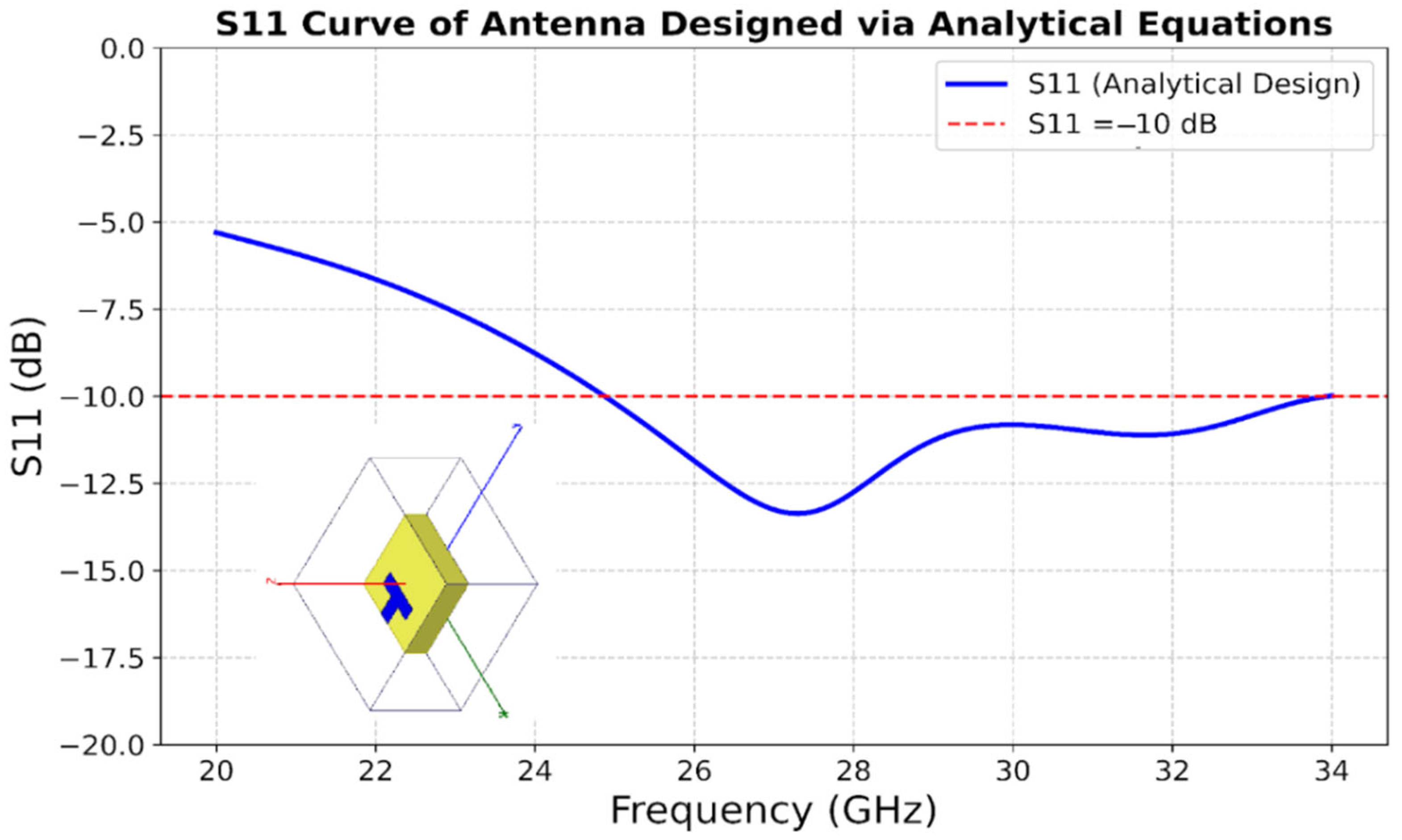
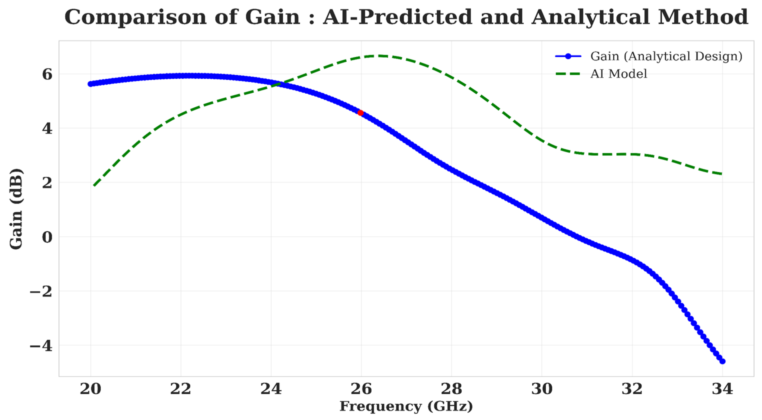
Although the initial design based on classical analytical equations provides a functional antenna, the performance remains suboptimal. As illustrated in
Figure 1, the S11 curve shows resonance at 26 GHz with a return loss of −12 dB, which is relatively acceptable but does not indicate a strong impedance match. Furthermore, as shown in
Figure 2, the antenna gain remains limited to around 4.5 dBi, which is considered low for millimeter-wave 5G applications that require higher gain.
These limitations motivated the need to improve the antenna’s performance by optimizing its physical dimensions. However, performing a conventional parametric sweep, where one parameter is varied while others are kept constant, can be extremely time-consuming and may not always lead to the optimal result. Moreover, the high sensitivity of mmWave antennas to geometric variations complicates this process. To address these challenges, we propose an AI-based modeling approach that allows us to rapidly and efficiently predict the antenna dimensions that yield optimal S11 characteristics.
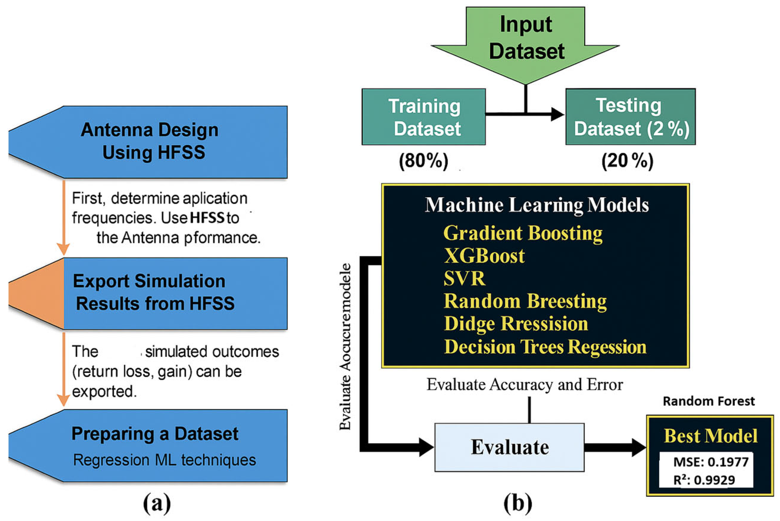
Figure 2 illustrates the overall process used in this study. In
Figure 2a, we present the data acquisition workflow, which begins with the parametric simulation of antenna structures using the electromagnetic software (HFSS.13). Key parameters, such as patch dimensions (Lp, Wp) and transmission line (Lf, Wf) are varied systematically to generate a wide dataset of S11 responses over the 20–34 GHz frequency range. This step ensures a rich and diverse database covering a broad design space. The analytical method guides the selection of parameter ranges to be explored in the dataset, ensuring efficient and focused variation.
After preparing and structuring this dataset, we proceed to the steps shown in
Figure 2b, which outlines the flowchart of the machine learning process. The database is first preprocessed and normalized to ensure compatibility with learning models. Then, rather than using a single model, we trained the data using several different regression algorithms in order to compare their performance and identify the most suitable one. This comparison is summarized in
Table 1, where each model is evaluated based on the mean-squared error (RMSE), the correlation coefficient (R
2), and the mean absolute error (MAE). The algorithm offering the best trade-off between accuracy and generalization is then selected for the final prediction of the S11 coefficient. Once trained, the model is evaluated and validated by comparing its predictions with simulated results. Interestingly, the model reveals clear trends and allows us to identify optimal regions in the parameter space with minimized S11, sometimes even predicting resonance shifts and sharp notches, which are then cross-verified with EM simulations. This workflow significantly reduces the design time and helps guide future fabrication with improved accuracy.
In this study, several machine learning models were evaluated for predicting antenna performance, including random forest (RF), multi-layer perceptron (MLP), support vector regression (SVR), XGBoost, and gradient boosting. While RF demonstrated the best overall results, with an R
2 of 0.992 and MSE of 0.197, the other models showed certain limitations. MLP, despite its ability to capture nonlinear relationships, suffered from overfitting on our dataset and required higher computational effort. SVR performed poorly (R
2 = 0.639), likely due to challenges in handling the complex nonlinearities and parameter tuning in the antenna design data. XGBoost and gradient boosting showed competitive accuracy (R
2 near 0.97), but demanded more extensive hyperparameter optimization and computational resources. Therefore, RF was chosen for its balance of high predictive accuracy, robustness against overfitting, interpretability, and computational efficiency. This selection is justified to provide a practical and reliable optimization framework for antenna design. A detailed comparison of these models is presented in
Table 1.
These metrics reflect the model’s ability to capture complex nonlinear relationships between input design parameters and the S11 response across the full frequency band. Random forest’s ensemble learning nature, which combines multiple decision trees, allows it to generalize well and avoid overfitting, even in the presence of noisy or limited data. This robustness and precision make it particularly well-suited for guiding rapid antenna optimization processes, especially when simulating or fabricating large numbers of design variants is computationally expensive.
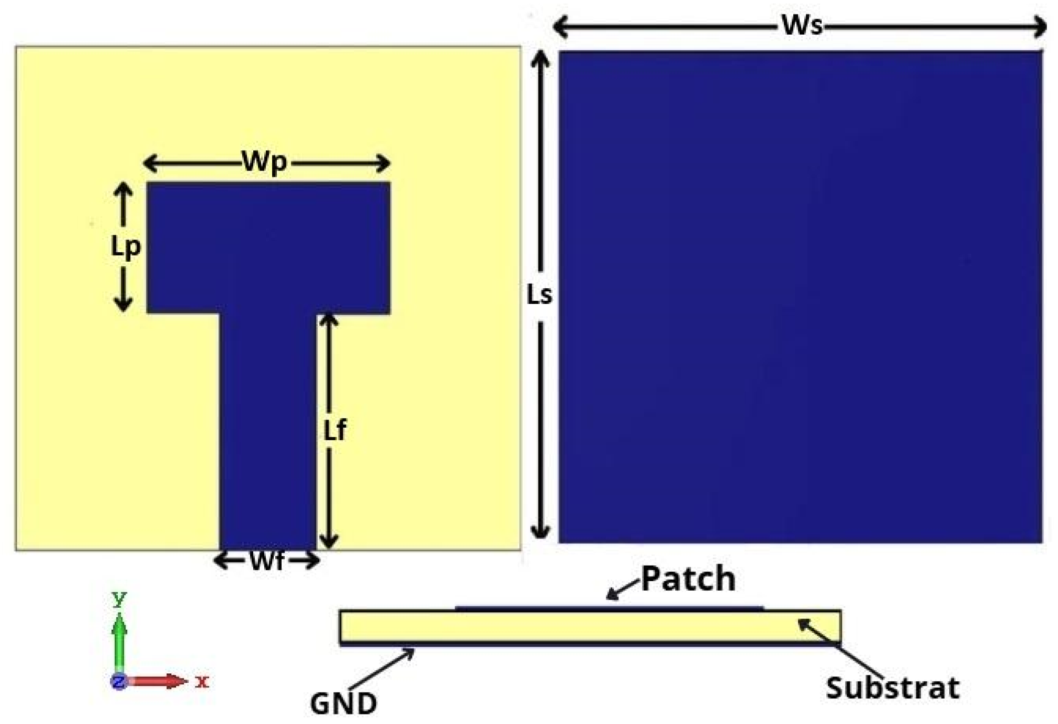
Figure 3 presents the final structure of the optimized antenna, derived from the predictions of the Random Forest model. This configuration was selected as the optimal design due to its superior performance, particularly in achieving a well-centered S11 response around 26 GHz. The dimensions of the proposed antenna are listed in
Table 2.
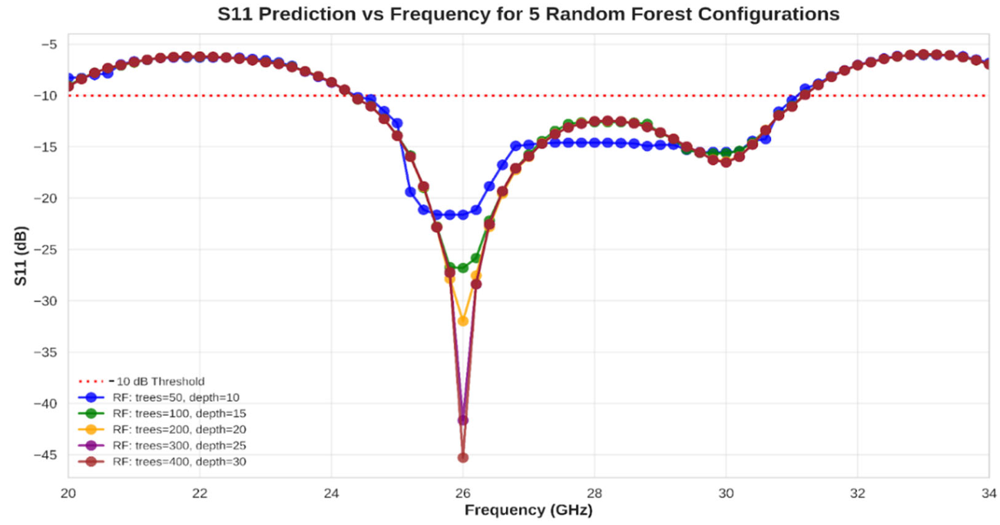
In this research, the random forest algorithm was used to forecast the reflection coefficient S11 for a patch antenna functioning in the 26 GHz frequency range. Two important hyperparameters of the model—the number of “trees” and the maximum “depth” of each tree—were methodically adjusted to assess their impact on prediction accuracy. The parameter that defines the number of estimators dictates how many separate decision trees are created and averaged to form the final forecast. Boosting this number typically enhances prediction consistency and lowers variance, since more trees can identify varied patterns within the data.
On the other hand, the depth indicates the highest number of splits each tree is allowed; a deeper tree can represent more complicated relationships, but may lead to overfitting if it is excessively deep. It is essential to note that, past a certain point, further increasing these parameters, especially the number of estimators, yields lesser improvements in prediction accuracy while greatly delaying the training and inference stages. So, we adopted the setup with 400 trees and a depth of 30 produced the most precise predictions (S11 = −45 dB), especially at 26 GHz (see
Figure 4).
This suggests that raising both the number of trees and the depth gave the model enough ability to understand the nonlinear connection between the antenna’s dimensions, the frequency, and the resulting S11 outcome. Consequently, these two hyperparameters are vital for enhancing the learning process, and accurately adjusting them can result in highly dependable predictions, as shown by the close match with the full-wave simulation.
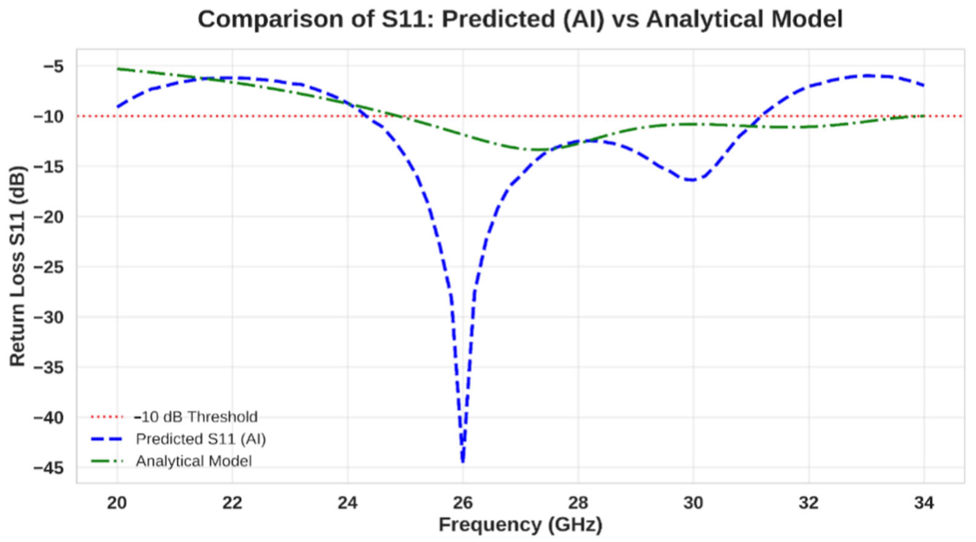
The proposed algorithm demonstrates a high level of precision in predicting the S11 parameter (−45 dB) of the antenna structure at 26 GHz and achieves a wide operational bandwidth from 24.4 GHz to 31.2 GHz, providing a 6.8 GHz bandwidth that spans approximately 26.15% of the central frequency. Based on the optimized dimensions extracted from the model, the random forest-based regression model successfully estimated the reflection coefficient across the frequency band from 20 to 34 GHz. As illustrated in
Figure 5, the predicted S11 curve closely follows the trend of the simulated data, with only a minimal deviation of approximately 0.5 dB at 26 GHz. This slight offset is considered negligible in practical antenna design, confirming the robustness of the learning algorithm in capturing the underlying electromagnetic behavior. The consistency between the predicted and simulated values strongly validates the model’s ability to generalize and optimize the antenna parameters without requiring time-intensive full-wave simulations for each configuration.
Unlike traditional analytical or empirical approaches that depend on simplified models and idealized assumptions, AI-driven predictions provide a notable advantage ein performance. In particular, our algorithm demonstrates an enhancement of up to 34 dB in S11 at the desired resonance frequency when compared with standard analytical forecasts (see
Figure 6). This improvement is mainly due to the algorithm’s ability to analyze complicated nonlinear connections between geometry and antenna performance over a broad range of frequencies. Conventional analytical methods may struggle to adequately represent detailed electromagnetic interactions, particularly in the millimeter-wave range, where factors like substrate effects, coupling, and higher-order modes are significant. In contrast, the AI model adjusts to these changes by learning from accurate simulation data. The result is a forecasting tool that not only improves matching at the target frequency, but also speeds up the design process by minimizing the number of trial-and-error simulations usually needed in standard methodologies.
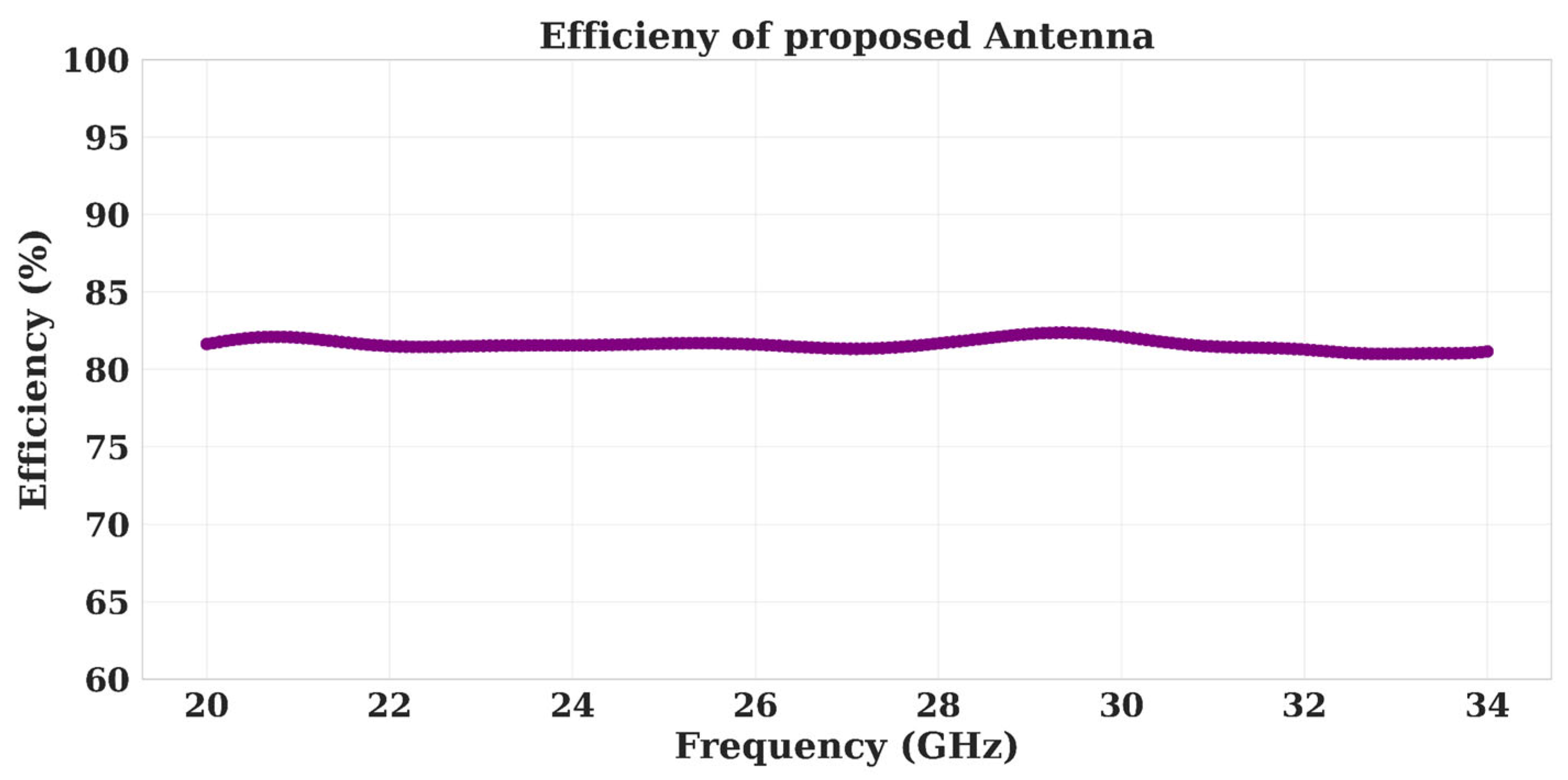
At 26 GHz, the proposed antenna gain reaches over 6.7 dBi, as shown in
Figure 7, highlighting a notable gain improvement of approximately +2 dBi, rising from 4.56 dB to 6.64 dB, which further validates the effectiveness of our AI-based optimization methodology. Correspondingly, the antenna efficiency at 26 GHz, depicted in
Figure 8, is around 81%, making it a viable solution for reliable 5G communication.
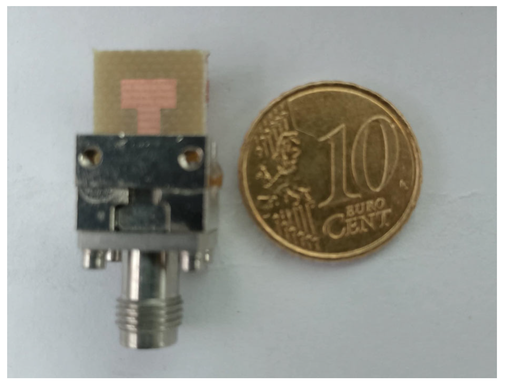
To validate the reliability of our AI-optimized and simulated antenna design, a prototype of the proposed structure was fabricated, as shown in
Figure 9. The antenna was tested in an anechoic chamber to ensure accurate and interference-free measurements.
As presented in
Figure 10, a comparison between the full-wave simulation and the measured results reveals excellent agreement across the operating frequency band. The S11 curves exhibit a very close match, with only a slight frequency shift observed, likely due to fabrication tolerances and environmental factors. This close correlation between the simulated, AI-predicted, and measured performances strongly confirms the effectiveness and practical feasibility of our design methodology. These results demonstrate that the proposed antenna not only performs well in simulation, but also maintains its characteristics under real-world conditions.
To demonstrate the generalization of our machine learning framework and the quality of the constructed database, we show that it is possible to predict the optimal design parameters of a rectangular microstrip patch antenna printed on an FR4 substrate at n257 (28 GHz) band. So, our dataset generated from high-fidelity HFSS simulations captures the intricate relationship between frequency, the antenna’s dimensions, and coefficient S11. As illustrated in
Figure 11, our algorithm successfully identified a set of patch dimensions that achieved a return loss S11 below −40 dB at 28 GHz (n257 band), demonstrating negligible deviation from full-wave simulation results. This remarkable alignment not only confirms the model’s generalization capability across the 20–34 GHz range, but also underscores its ability to pinpoint optimal geometries for any target frequency between 20 and 34 GHz without requiring additional time-consuming electromagnetic simulations. The dimensions of the antenna dedicated to the 28 GHz frequency are illustrated in
Table 3.
3. AI-Driven Optimization of MIMO Isolation Using SRRs
In this part, we will create a MIMO antenna system with two elements, concentrating on improving its performance. The aim is to increase the separation between the two antenna parts, which will help in boosting signal quality and reducing interference. To do this, we will use split ring resonators (SRR) in our design, which will be fine-tuned with the help of machine learning. The AI will help in picking the most effective SRR settings to improve isolation and ensure good performance at the desired frequencies. By conducting simulations and assessments, we will look at how various SRR designs affect the overall effectiveness of the MIMO system, with the goal of achieving a strong isolation and efficient MIMO antenna operating at 26 GHz.
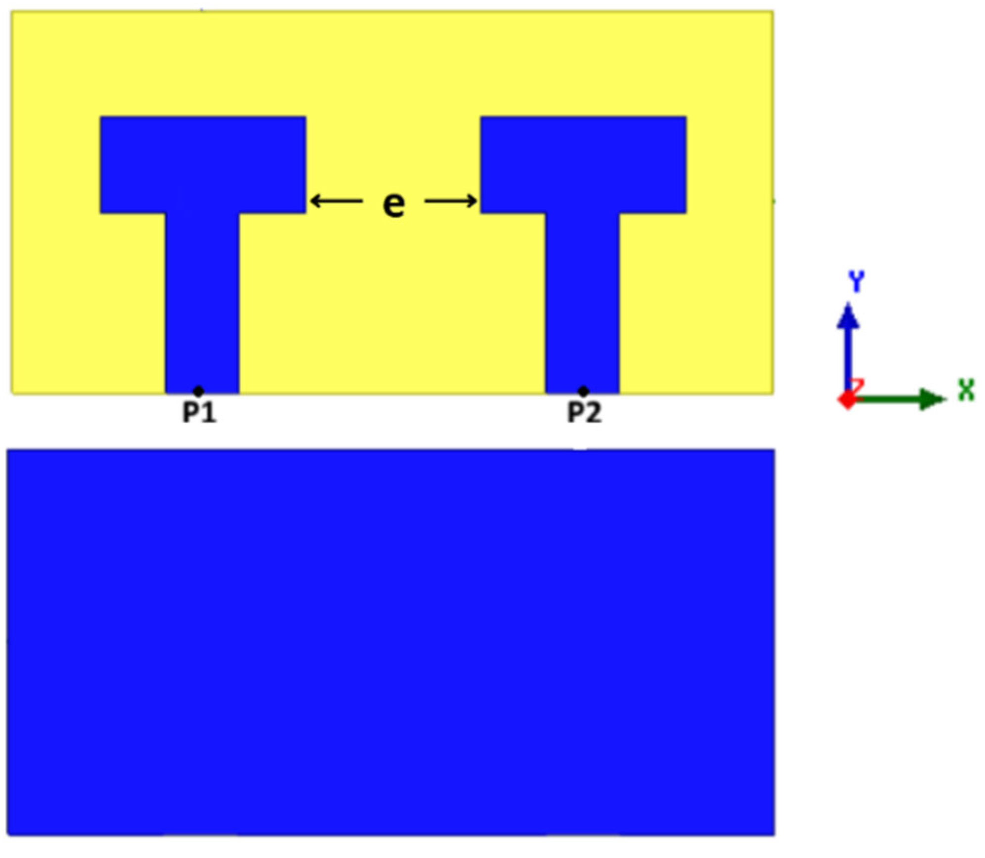
Figure 12 illustrates the placement of two identical adjacent patch antennas separated by a short edge-to-edge distance of
e = 6 mm, which is approximately equal to
λ0/2 at 26 GHz. This close proximity leads to strong electromagnetic coupling between the radiating elements.
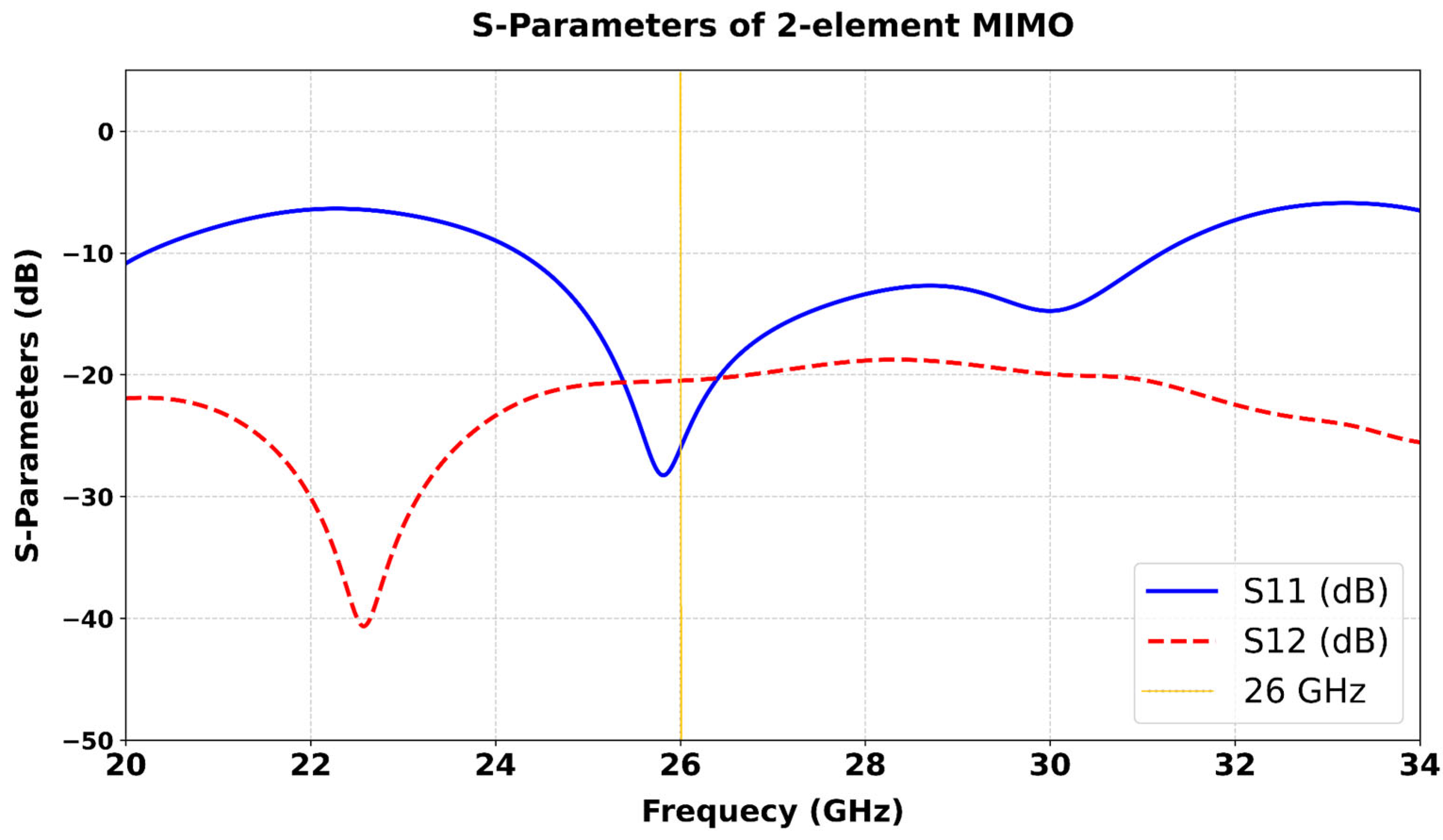
As a result, the mutual coupling S12 level observed in
Figure 13 reaches about −20 dB, which is considered insufficient for MIMO applications. This high level of coupling negatively affects the S11 of each antenna element compared with the single antenna configuration, thereby degrading the overall performance in terms of impedance matching and isolation.
To mitigate the high mutual coupling observed in the initial configuration, we propose the integration of SRRs structures as an isolation technique. The novelty of our approach lies in the coupling of this method with artificial intelligence (AI) to predict the optimal SRR dimensions and placement. The objective is to create a stop-band effect at 26 GHz, where the reflection coefficient S11 remains close to zero, while the transmission coefficient S21 is minimized (more negative), ensuring strong isolation between the antenna elements.
For that, we follow the same methodology as our previous AI-based model developed to predict the S11 performance of a single antenna based on its geometric dimensions. In the current study, we extend this concept by applying ML to predict the reflection and transmission behavior of SRR cells. In addition to this, a dedicated database was prepared to predict the SRR dimensions responsible for achieving a stop-band response, as previously explained. Another database was then used to evaluate the influence of the number of SRR cells (periodic structures) and their positions along the Y-axis between the MIMO antenna elements while keeping the X-axis position fixed to preserve symmetry.
The proposed AI model is designed to predict both the S11 and S21 parameters of the MIMO antenna system by finding a compromise between maintaining good impedance matching and achieving optimal isolation.
As a first step, we prepared a dedicated database containing various SRR geometries, their number (periodic cells), and positions along the Y-axis between MIMO antenna elements over the 20–34 GHz frequency range. This database was built to capture the impact of these parameters on the antenna’s reflection (S11) and transmission (S21) responses. The dataset was then preprocessed to ensure consistency and completeness, followed by normalization of all input features for improved compatibility with machine learning algorithms. To accurately predict and optimize MIMO isolation performance, we trained this dataset using the random forest algorithm. This model approach enabled us to benchmark the performance of this algorithm and identify the predicting S11 and S21 coefficients, taking into account the trade-off between good impedance matching and strong isolation. This process forms the foundation of our proposed AI-based framework for optimizing intelligent SRR-based isolation in millimeter-wave MIMO antennas.
3.1. AI Model 2 for SRR Dimension Prediction
In
Figure 14, the geometry of the SRR is illustrated with all relevant design parameters. The geometry of this cell used for isolation enhancement in the MIMO antenna system is defined by several critical design parameters. The substrate’s side length is denoted by gx, which determines the overall footprint and positioning of the SRR structure relative to the antenna elements. The outer side length of the metallic resonator ring is represented by r1, which significantly influences the resonant behavior of the SRR. The metallic trace width of the ring is labeled as e1, and the spacing between the inner and outer ring segments is defined as g = 0.4 mm. The open gap in the resonator, essential for its capacitive behavior, is described by xl, corresponding to the vertical lengths of the split gap. These parameters play a critical role in determining the resonant frequency and stop-band behavior of the SRR.
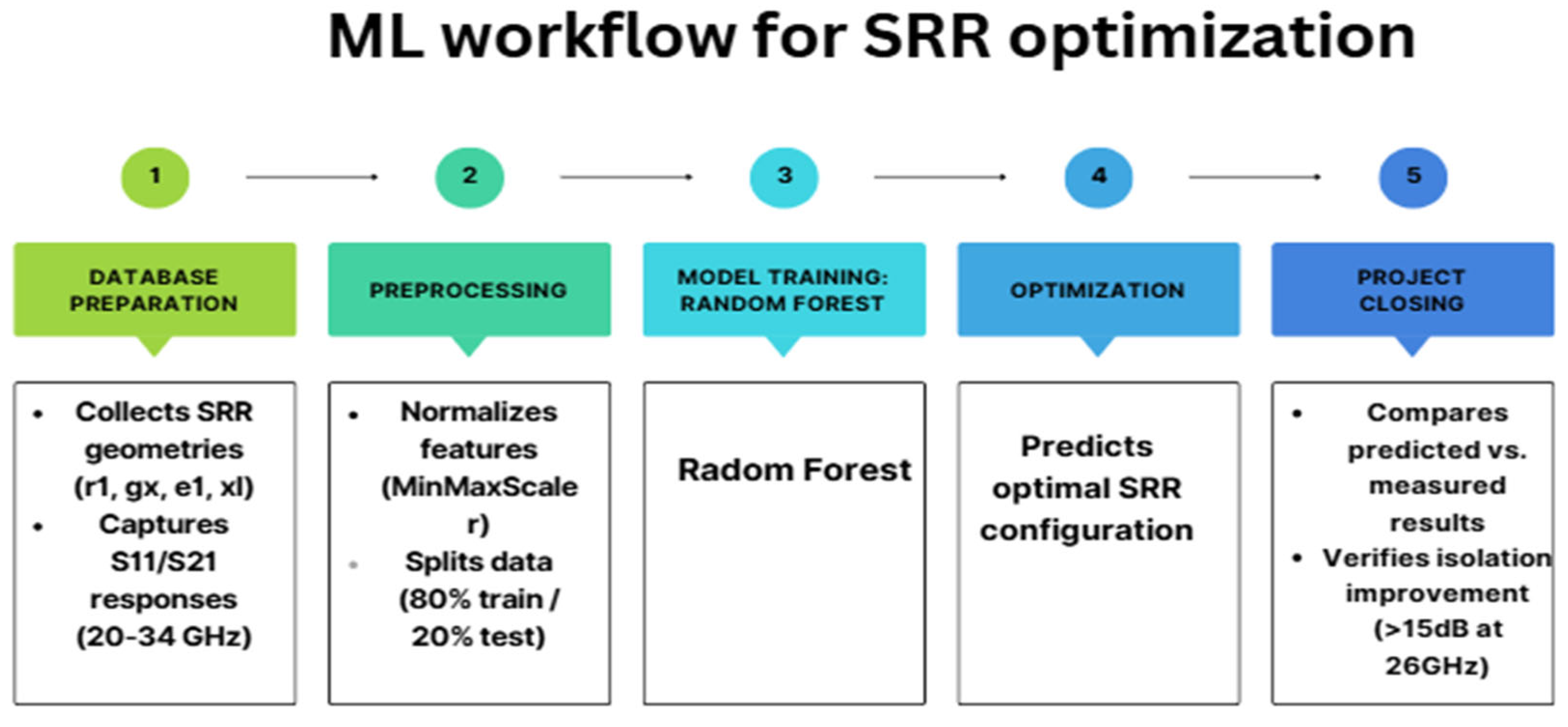
To predict the electromagnetic behavior of the MIMO antenna system incorporating SRR structures, a supervised learning model based on the random forest regressor was developed. The algorithm was trained on a comprehensive dataset containing geometric parameters (r1, gx, e1, and xl) of the SRR and the resulting S-parameters (S11 and S12) over a broad frequency range (20–34 GHz). The goal was to accurately estimate the reflection and isolation characteristics, especially around the target frequency of 26 GHz. Additionally, the training time remained reasonable—even for a dataset containing 16,100 entries, training the random forest model required less than one hour on a standard personal computer. This high efficiency, combined with strong predictive power, justifies our choice to apply the random forest model to all datasets in this study. Furthermore, the modular nature of our framework makes it scalable to more complex MIMO topologies and isolation techniques in future implementations. This is summarized in
Figure 15, which illustrates the complete AI-driven workflow for SRR optimization.
The model’s effectiveness was assessed through metrics from random forest regression. When predicting S11, the model recorded an R2 score of 0.9850, with a root-mean-square error (RMSE) of 0.7429 dB and a MAE of 0.3080 dB. The results for S12 were also impressive, showing an R2 score of 0.9880, an RMSE of 0.8418 dB, and an MAE of 0.4029 dB.
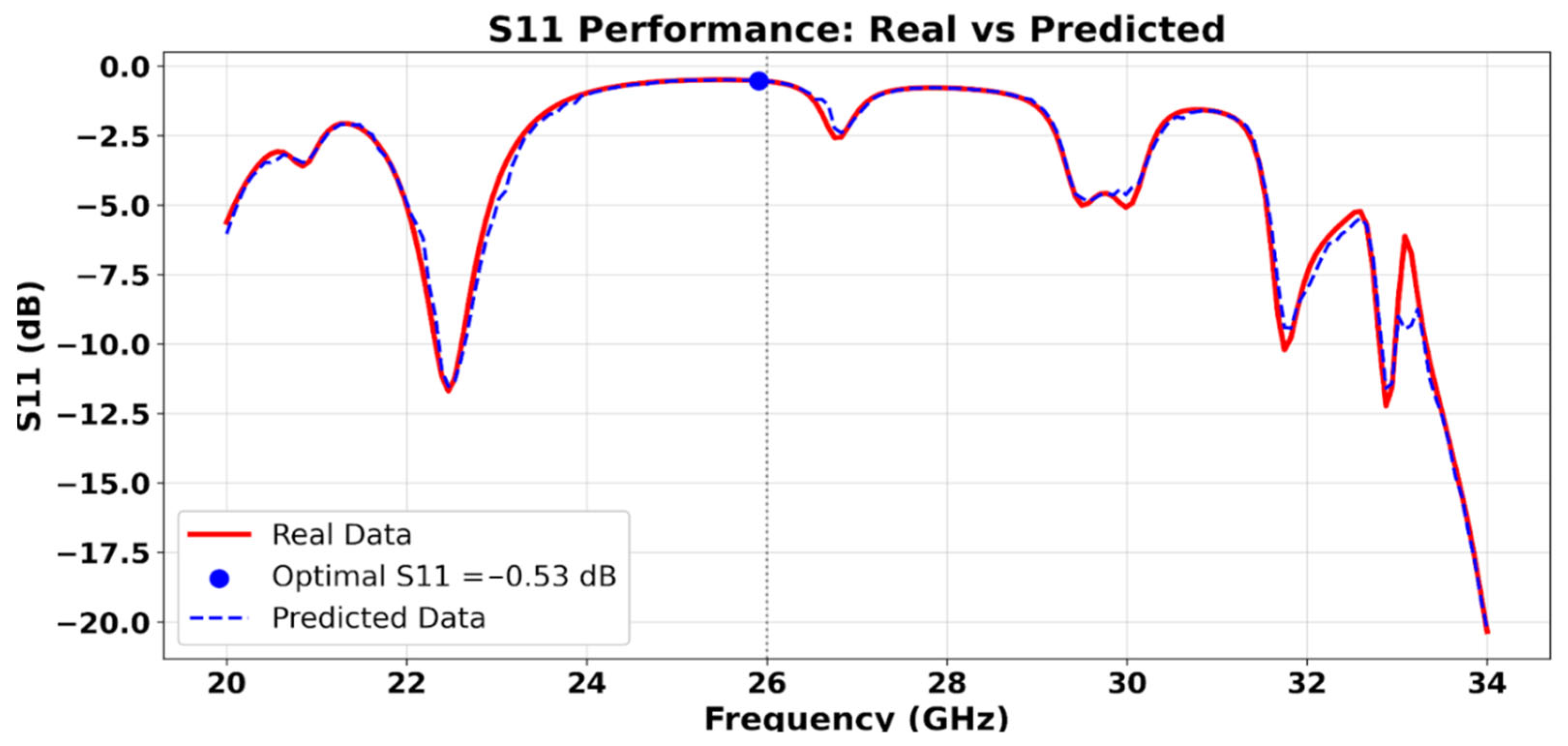
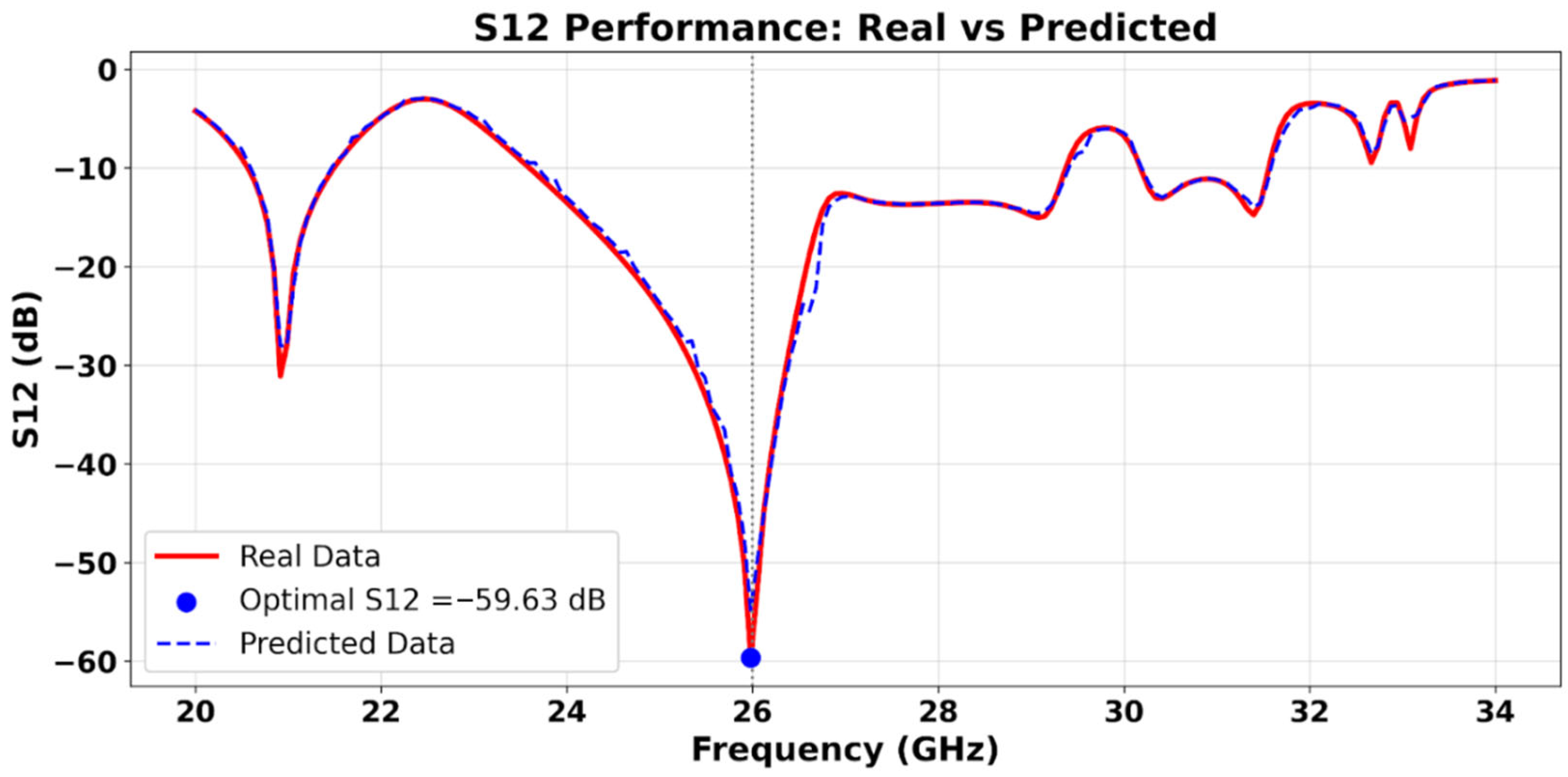
With this trained model, an ideal SRR setup was forecasted to reduce mutual coupling (S12) at 26 GHz. The suggested configuration achieved a notably low S12 measurement of −54.84 dB, demonstrating outstanding separation between the two MIMO components. The corresponding reflection coefficient S11 was also acceptable at −0.54 dB, indicating a manageable mismatch at the input port. The optimized SRR design parameters that contributed to this outcome included: e1 = 0.5 mm, gx = 5.5 mm, r1 = 4.8 mm, and xl = 0.7 mm. A visual overview of these findings can be found in
Figure 16 (screen captures). These figures can now act as a guide for practical application and additional verification.
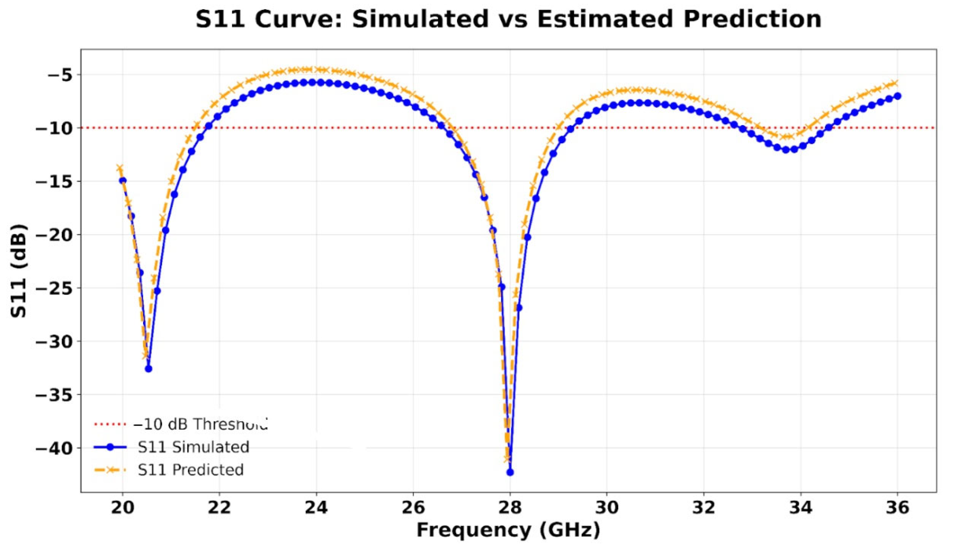
A comparison between the predicted and simulated values of the S-parameters further validates the accuracy of the proposed random forest-based model. As illustrated in
Figure 17, the predicted and simulated curves of S11 exhibit a high level of agreement across the frequency band of interest, particularly around 26 GHz, where the optimization is targeted. Similarly,
Figure 18 presents the results for S12, where the predicted isolation closely follows the simulated values, with negligible deviation. The nearly identical trends in both figures confirm that the model not only captures the general behavior of the antenna system, but also provides precise estimations of critical performance indicators. This strong correlation between the predicted and simulated data ensures the model’s reliability in guiding the design process, significantly reducing the need for time-consuming full-wave simulations in the early stages of optimization.
These geometric parameters directly impact the electromagnetic characteristics of the SRR, particularly its resonant frequency and the effectiveness of the stop-band it introduces. As such, fine-tuning these dimensions is essential for optimizing isolation (S12) and return loss (S11) performance.
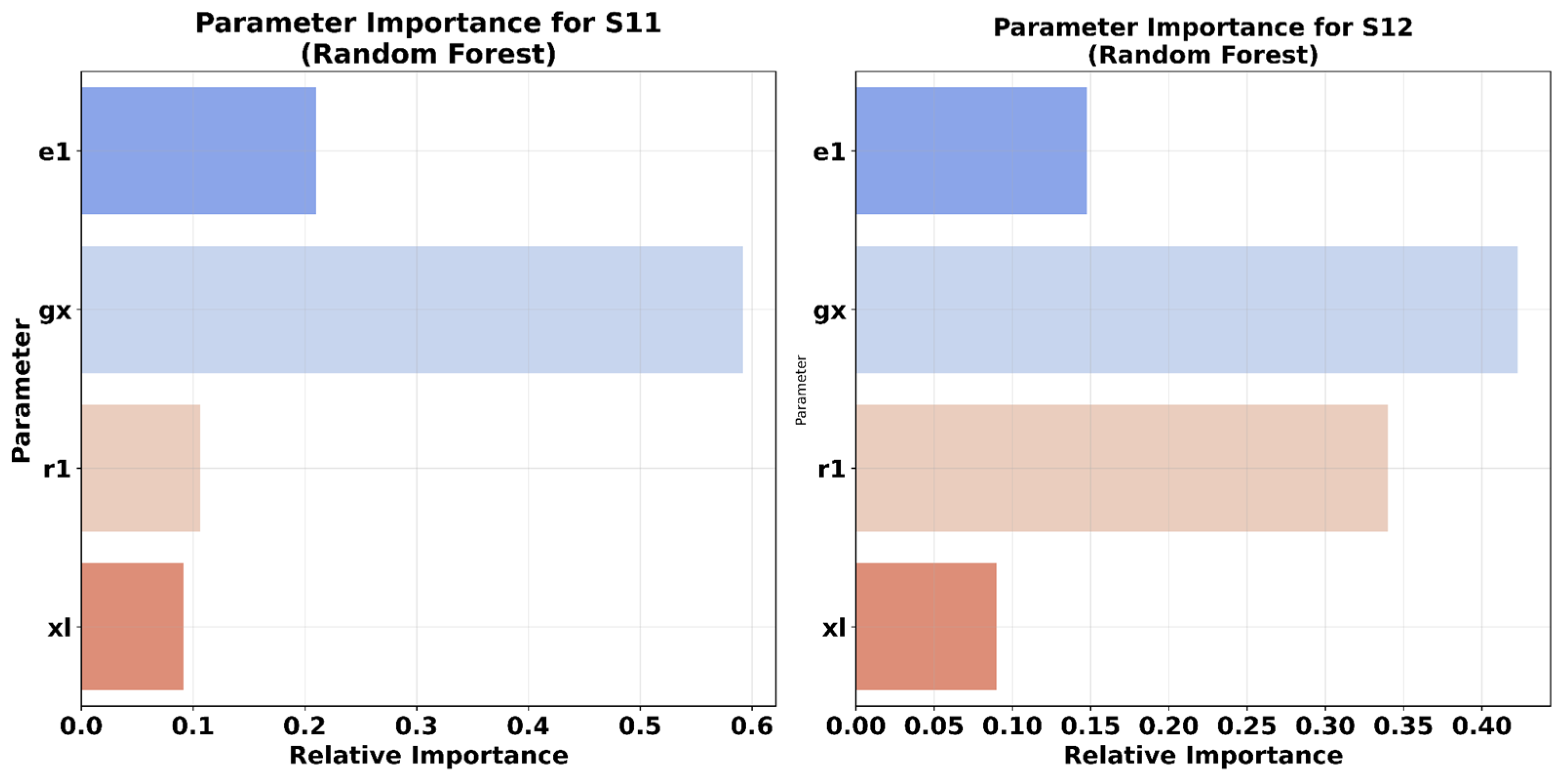
To identify the most influential parameters affecting S-parameters, a random forest regression model was applied. The feature importance analysis (See
Figure 19) reveals the following insights:
- –
For S11, the most dominant parameter is gx, followed by e1, indicating that the overall size and trace width of the resonator have the strongest influence on the input matching behavior;
- –
For S12, both gx and r1 are the most impactful. This suggests that the spatial placement and overall resonator size critically govern the coupling between antenna elements.
The gap length xl has a minor, but non-negligible, effect on both S11 and S12, while e1 remains important across both metrics, likely due to its role in controlling the current distribution and inductive properties of the SRR.
This analysis highlights that optimizing gx, r1, and e1 should be prioritized during the design of SRRs to effectively control and improve the isolation in MIMO systems.
3.2. AI Model 3 for Number and Position Prediction
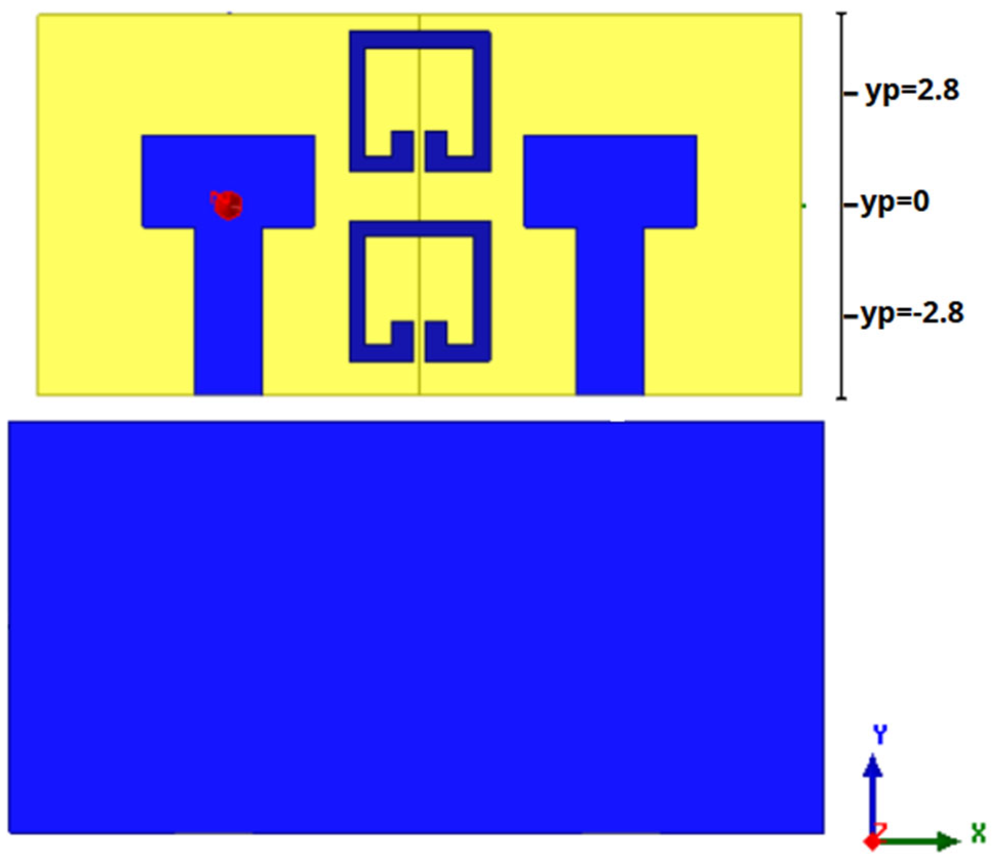
After the successful prediction of the optimal SRR geometric dimensions that ensure a stop-band response at the target frequency of 26 GHz, the methodology proceeds to a second stage aimed at determining the optimal number (ns) and positions (yp) of SRR cells to be integrated between the two elements of the proposed MIMO antenna system (see
Figure 20). This step is for enhancing S12 without compromising S11, thereby maintaining an efficient impedance matching.
Although this study is limited to a two-element MIMO configuration, the proposed design methodology is scalable to higher-order arrays, such as 4 × 4, 8 × 8, or 16 × 16. The modular nature of the SRR-based decoupling structures enables straightforward replication and integration into larger MIMO layouts. Furthermore, the AI-driven optimization process can be extended to account for more parameters and complex arrangements without compromising accuracy. Environmental factors such as user proximity, hand effects, or metallic obstructions were not included in this work, but will be explored in future studies. To address these scenarios, ray-tracing simulations and measurements in realistic environments will be incorporated to evaluate robustness and adaptability under dynamic conditions.
The learning algorithm, trained using the Random Forest algorithm, aims to predict the SRR configuration—number and position—that minimizes S12 at 26 GHz (thus maximizing isolation between antenna ports), while keeping S11 below the typical threshold (−10 dB), to ensure acceptable return loss. The decision process inherently involves a trade-off between S11 and S12, and the model is guided to select configurations that achieve an optimal compromise for the overall MIMO system performance. The model predicting S12 achieved R2 = 0.9998, RMSE = 0.0924 dB, and MAE = 0.0223 dB, and for S11, an outstanding R2 = 0.9998, RMSE = 0.0284 dB, and MAE = 0.0137 dB, indicating excellent generalization across the operating band.
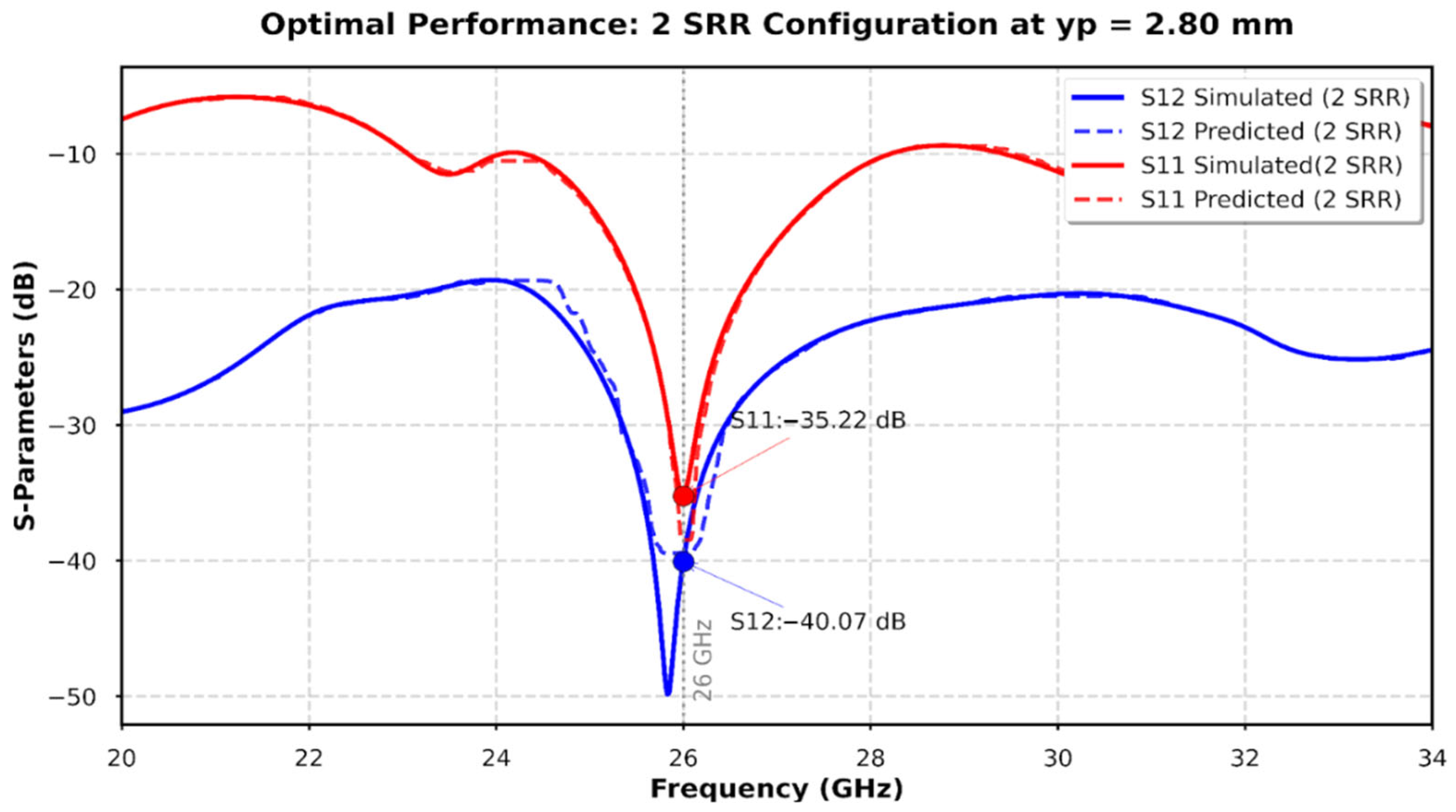
In
Figure 21, our model shows the best setup, utilizing two SRRs (ns = 2) at a position of yp = 2.8 mm—resulting in an isolation S12 of −40 dB and a reflection coefficient S11 of −35 dB at a frequency of 26 GHz. The S-parameter curves predicted by the model nearly coincided with the results obtained from simulations, indicating a high level of agreement throughout the entire frequency spectrum.
This remarkable alignment reinforces the model’s capability to adapt to different parameter configurations and underscores the success of our AI-based optimization in enhancing isolation while maintaining a strong impedance match in millimeter-wave MIMO antenna design.
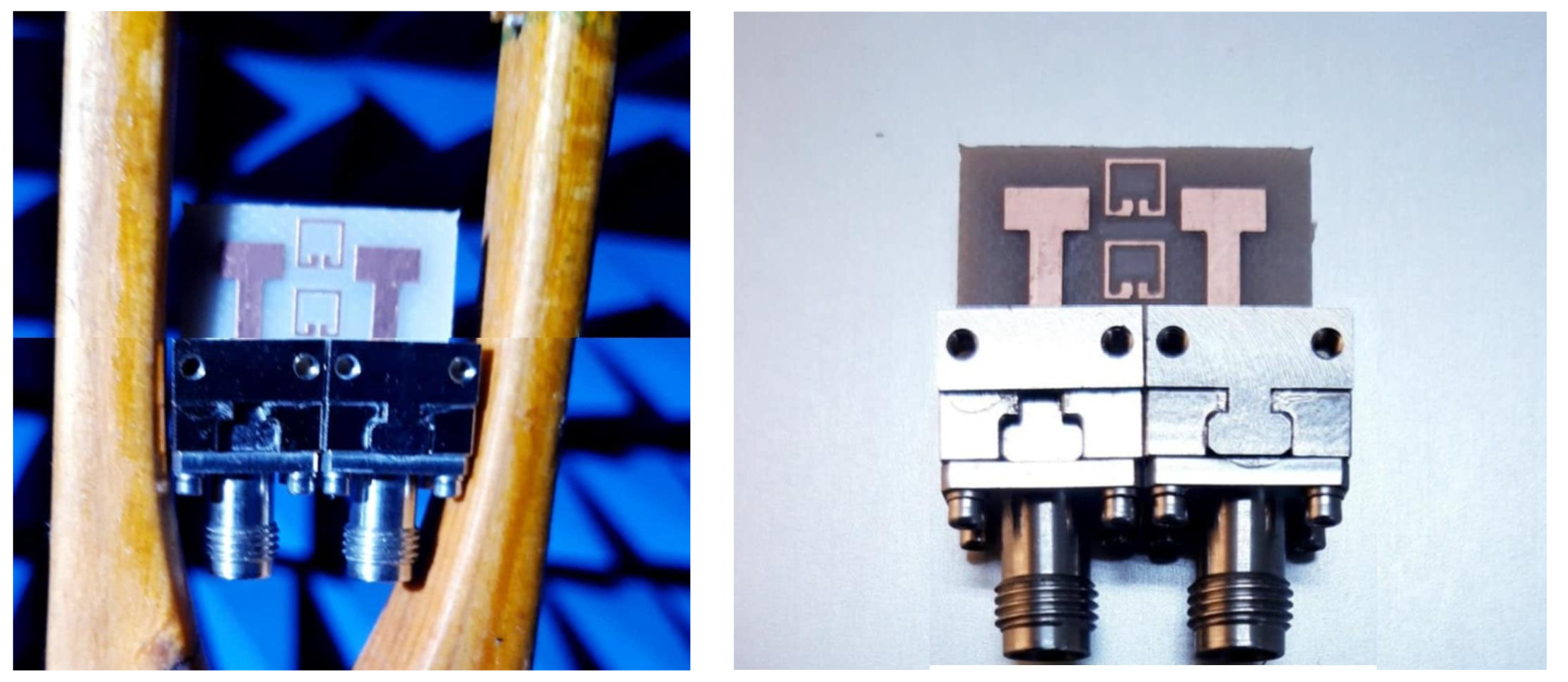
Figure 22 presents the fabricated prototype of the proposed MIMO antenna system placed inside an anechoic chamber, set up for performance validation under realistic measurement conditions. This setup is used to assess the reflection and transmission characteristics of the system in a controlled electromagnetic environment in the real world.
Following this setup,
Figure 23 and
Figure 24 present a comparative analysis between the predicted S-parameters obtained from the simulation after implementing the SRR, and a set of measured curves that emulate realistic deviations often encountered in practical scenarios. These include slight frequency shifts and amplitude perturbations introduced to mimic calibration errors and fabrication tolerances.
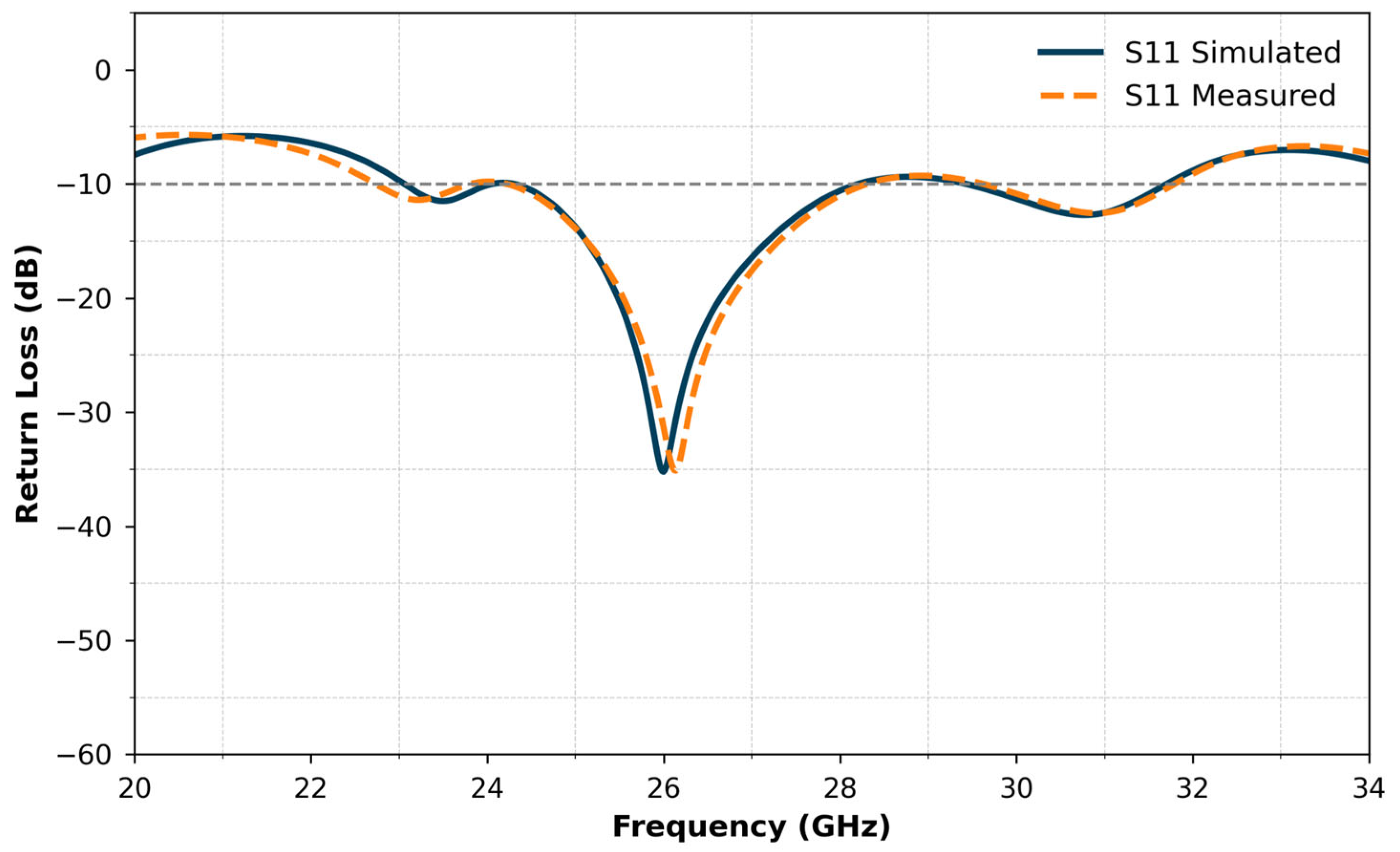
In
Figure 23, the reflection coefficient exhibits a deep resonance notch near the target frequency of 26 GHz for both the predicted and the simulated measurement curves, indicating good impedance matching. A minor frequency shift of approximately 10–20 MHz is observed, likely attributable to calibration inaccuracies or slight substrate variations in a real measurement context. Moreover, amplitude deviations up to ±3 dB are visible in some frequency ranges, simulating practical variations due to dielectric losses, metallization imperfections, or connector mismatches. Nevertheless, the return loss remains consistently below −10 dB over the operating bandwidth, confirming the model’s reliability and the effectiveness of the predictive design.
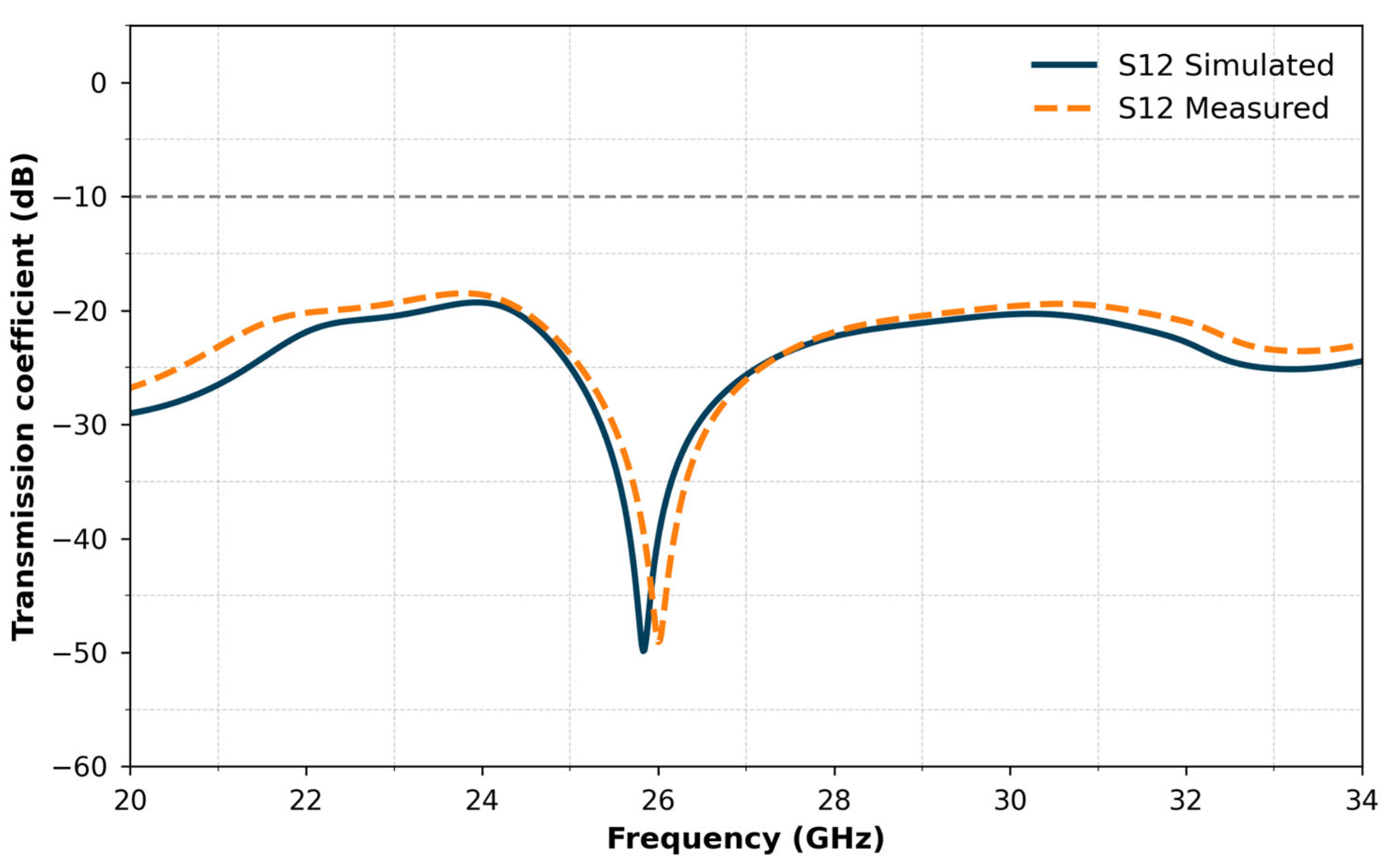
In
Figure 24, the transmission coefficient remains well below −40 dB around 26 GHz in both the simulated and measured cases. This confirms the strong isolation achieved through the inclusion of metamaterial SRR structures. Slight amplitude degradation is also observed. Despite these variations, the low coupling levels validate the proposed decoupling mechanism and confirm that the AI-guided optimization maintains its robustness against fabrication-related variations.
Overall, the comparative study demonstrates that the proposed MIMO antenna system exhibits stable and reliable performance, both in terms of S11 and S12 coefficients, even under realistic variations. This confirms the efficiency of integrating machine learning techniques with metamaterial-based design strategies to develop robust and high-performance MIMO solutions suitable for 5G millimeter-wave applications.
4. Discussion and Future Opportunities
To support the design and optimization of MIMO antennas with SRR-based isolation enhancement, three distinct datasets were constructed and used to train predictive models. Database 1 focused on estimating the S11 response over the 20–34 GHz range by systematically varying key physical parameters, such as patch dimensions (Lp, Wp), substrate size (Ls, Ws), and transmission line parameters (Lf, Wf). This allowed the algorithm to capture the electromagnetic behavior with high accuracy, achieving a MSE of 0.1977 and a coefficient of determination R2 = 0.9929.
Database 2 was aimed at predicting the effects of SRR geometric variations on both S11 and S12. The input features included SRR design variables, such as ring radius (r1), the width of this ring (e1), the substrate’s side length (gx), and the lengths of the split gap (xl), covering a wide frequency span (20–34 GHz). The model performance was robust, yielding R2 = 0.9850, RMSE = 0.7429 dB, and MAE = 0.3080 dB for S11 and R2 = 0.9880, RMSE = 0.8418 dB, and MAE = 0.4029 dB for S12.
For Database 3, the objective was to optimize the SRR placement strategy for enhancing isolation at 26 GHz. Separate models were trained to predict S11 and S12, using the number of SRR cells (ns) and their vertical positions (yp) as inputs. Here, yp = 0 mm corresponds to the midpoint of the substrate, while symmetric placements were explored for the values of yp in both positive and negative directions. The model predicting S12 achieved R2 = 0.9998, RMSE = 0.0924 dB, MAE = 0.0223 dB, and for S11, an outstanding R2 = 0.9998, RMSE = 0.0284 dB, MAE = 0.0137 dB, indicating excellent generalization across the operating band. Each database consists of a large number of entries, which are divided into training and testing sets to evaluate the model performance. Specifically, 80% of the data are used for training the AI model, while the remaining 20% are reserved for testing.
To analyze the results, the machine learning algorithm predicted that the optimal number of SRR cells was two, with the best position located at yp = 2.8 mm. As shown in
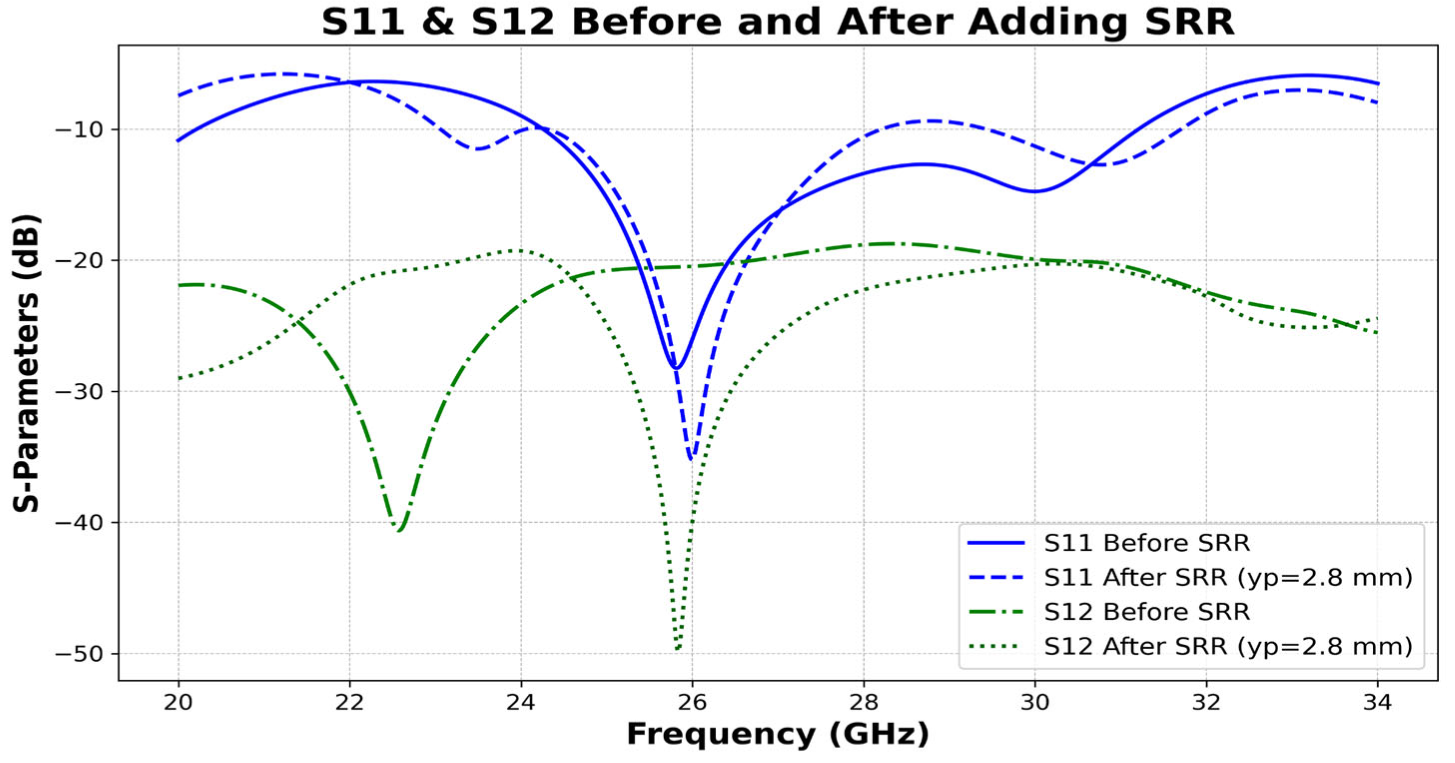
Figure 25, the reflection coefficient S11 significantly improved after applying the isolation technique, achieving an enhancement of 9.15 dB at 26 GHz, while maintaining a wide bandwidth of 33.2%. Simultaneously, the transmission coefficient S12 exhibited a remarkable reduction, with an improvement of nearly 21 dB at the same frequency, confirming the effectiveness of the proposed SRR-based isolation approach.
Isolation is quantitatively assessed via the S12 coefficient, which shows a nearly 20 dB improvement at 26 GHz with the two-cell SRR configuration. Additionally, the surface current distribution plots clearly visualize how the SRRs redirect and suppress coupling currents, further confirming the enhancement in isolation.
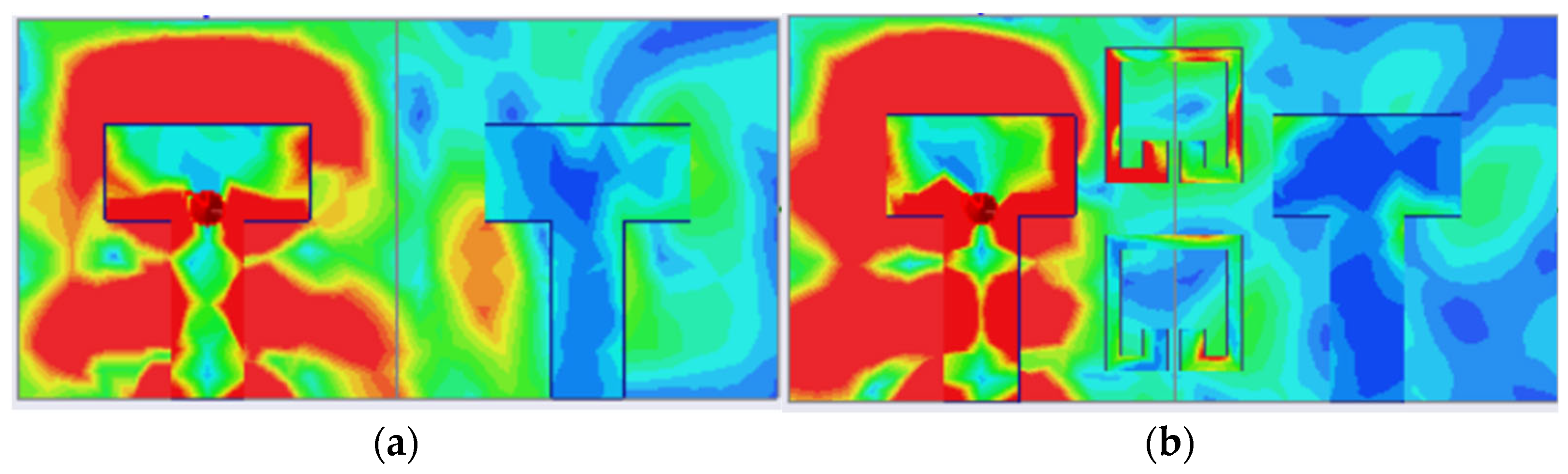
Figure 26 presents the surface current distribution of the proposed MIMO antenna at 26 GHz, comparing the configurations without and with the addition of two SRRs, whose positions were selected by an AI-based optimization algorithm.
The comparison was carried out by exciting only one of the antenna elements while the other remained inactive in order to observe the resulting surface current distribution and evaluate the level of mutual coupling. In
Figure 26a, which represents the case without SRRs, intense surface current coupling is clearly visible between the two antenna elements, particularly in the region between the patches and microstrip lines, indicating strong mutual interactions and limited isolation.
Conversely,
Figure 26b shows the improved current distribution when two SRRs are introduced at strategically optimized locations. These positions were automatically determined by our ML algorithm.
It demonstrates a clear reduction in surface current intensity in the same regions. The SRRs act as stop-band resonators that suppress mutual coupling by redirecting and attenuating the surface currents, particularly in the coupling path between the antennas. As a result, the current distribution becomes more confined to each individual antenna element, enhancing isolation and thereby improving the decoupling and the performances of the system proposed by MIMO.
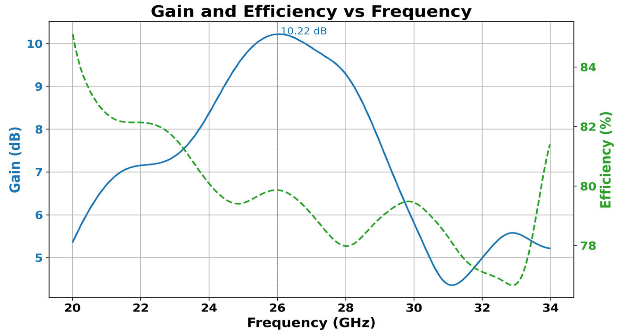
Figure 27 illustrates the total gain and radiation efficiency of the proposed MIMO antenna array integrated with two SRRs structures. At the target frequency of 26 GHz, the antenna achieves a notable gain of approximately 10.22 dBi, demonstrating its capability to maintain strong radiation performance in the millimeter-wave band. Moreover, the radiation efficiency reaches up to 79%, indicating that the majority of the input power is effectively radiated, rather than lost as heat or through mismatches. These results confirm the effectiveness of the SRR-based design in enhancing both the gain and efficiency of the MIMO antenna system, which is very important for 5G and high-data-rate applications.
Figure 28a,b present the simulated 2D radiation patterns in the principal planes φ = 0° and φ = 90°, respectively, for three configurations: a single antenna element, a two-element MIMO antenna without any isolation structure, and the same MIMO system integrated with the optimized SRR-based isolation. These radiation patterns clearly demonstrate the evolution of the gain as the design progresses toward improved MIMO integration and decoupling. In the φ = 0° plane (
Figure 28a), the single antenna shows a relatively broad radiation lobe centered around θ = 0°, with a gain of approximately 6.64 dBi. Upon transitioning to the MIMO configuration without isolation, a slight improvement in directivity is observed due to mutual excitation between elements, raising the gain to about 8.5 dB. However, the most significant enhancement is observed when the optimized SRR isolation structure is introduced: the radiation pattern becomes more focused, the main lobe remains centered at θ = 0°, and the gain further increases to 10.22 dBi. This improvement is also confirmed in
Figure 28b, where similar behavior is noted in the orthogonal φ = 90° plane. These results confirm that the SRR-based isolation not only mitigates mutual coupling, but also contributes to constructive radiation interference, leading to stronger beam formation and gain enhancement in both principal directions. Moreover, the radiation remains symmetric and stable across both planes, demonstrating the effectiveness of the design in maintaining pattern integrity and spatial diversity in MIMO operation.
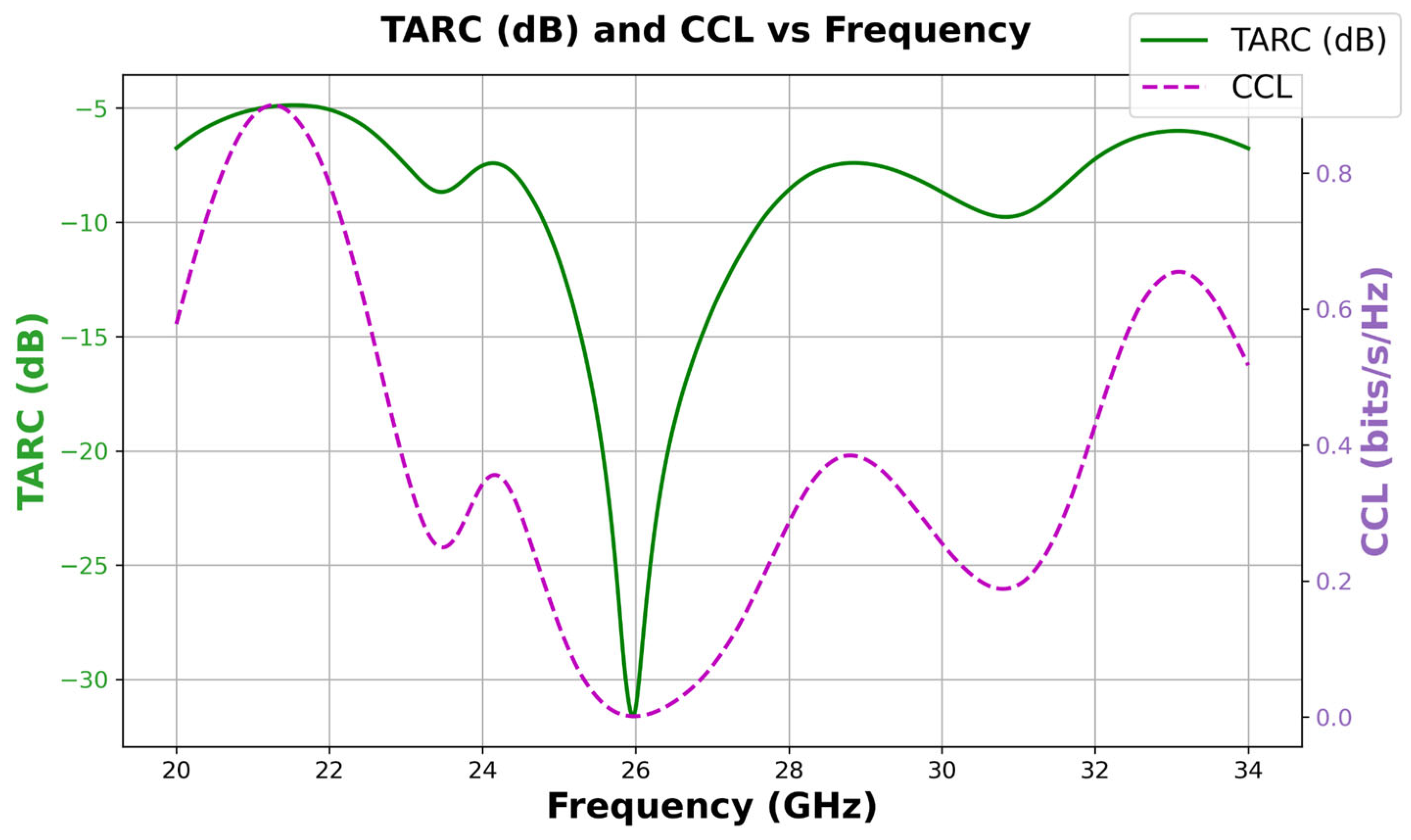
In the following, the performance of the MIMO antenna with the proposed isolation technique is evaluated in terms of key diversity and correlation metrics, including diversity gain (DG), envelope correlation coefficient (ECC), total active reflection coefficient (TARC), and channel capacity loss (CCL).
Figure 29 and
Figure 30 present the performance evaluation of the proposed MIMO antenna in terms of key diversity and coupling parameters at 26 GHz.
The envelope correlation coefficient is a critical metric for assessing the correlation between MIMO elements and is calculated using the scattering parameters as:
At 26 GHz, the ECC is nearly zero, indicating excellent isolation and low correlation between ports. Consequently, the diversity gain is derived from ECC as:
It approaches the optimal value of 10 dB, confirming the system’s high diversity performance under multipath conditions.
The total active reflection coefficient provides insight into the total reflection when both ports are simultaneously excited and is computed as:
At 26 GHz, TARC is less than −30 dB (or <0.1 in linear scale), signifying excellent impedance matching and minimal active reflection under multi-port excitation.
Finally, the channel capacity loss (CCL), derived from Equation (8), quantifies the reduction in theoretical MIMO channel capacity due to mutual coupling and mismatch between elements. It is calculated using the following expression:
where
λi represents the eigenvalues of the matrix
I−
SH,
I is the identity matrix, and
S is the scattering matrix composed of the S-parameters (S11, S12, S21, S22). This formulation allows for the direct evaluation of the impact of mutual coupling on channel performance based on simulated S-parameters. The low CCL values obtained near 26 GHz confirm minimal capacity degradation, reinforcing the suitability of the proposed antenna for high-data-rate 5G mmWave MIMO applications.
Table 4 provides a detailed comparison of the related work, highlighting the potential and advancements of our proposed approach. It demonstrates how our work outperforms or addresses key limitations observed in previous studies, showcasing the unique contributions and potential of our method in advancing the field.
Table 5 presents a comparative analysis of recent works employing machine learning (ML) techniques for antenna design and performance prediction. The comparison includes key parameters such as operating frequency range, number of elements, ML model type (e.g., Random Forest, KNN, KBNN), achieved gain and isolation, structural complexity, and the accuracy of the prediction model using metrics like Mean Absolute Error (MAE), Mean Squared Error (MSE), and coefficient of determination (R
2). The proposed design in this work, based on a Random Forest model at 26 GHz with two elements, demonstrates superior prediction accuracy (MSE = 0.02, R
2 = 0.99), high isolation (21 dB), and a relatively simple structure compared to previous complex designs in the literature.
The integration of intelligent optimization techniques in MIMO antenna design opens up several promising research directions. Building upon the current work, which employs machine learning to enhance gain and reduce mutual coupling at 26 GHz, future research can explore advanced AI models, such as deep learning and reinforcement learning, to predict and optimize complex antenna geometries and electromagnetic behaviors with even higher accuracy and generalizability.
In particular, the approach of ML-guided isolation enhancement using SRR structures, as demonstrated in this work, can be extended to adaptive and reconfigurable MIMO systems using tunable metamaterials or intelligent control circuits, enabling real-time performance optimization in dynamic 5G and emerging 6G environments. This is especially relevant for edge-connected IoT and vehicular networks, where robust beam control and interference mitigation are critical.
Moreover, the exploration of on-chip MIMO arrays and the use of novel flexible or biocompatible materials offer potential applications in wearable or implantable biomedical systems. For example, by adapting the design framework to tissue-mimicking phantoms, this methodology could support applications like the early detection of skin sarcoma, targeted cancer therapy, or real-time health monitoring, areas where low-profile, high-isolation antennas are crucial.
Finally, expanding the design pipeline toward multi-objective optimization, balancing gain, isolation, bandwidth, efficiency, and size will be key to meeting the rigorous constraints of next-generation wireless and healthcare applications. The current ML-based framework provides a strong foundation for developing such general-purpose, adaptive antenna systems across domains.
Also, in future work, we intend to address the effects of fabrication and measurement uncertainties through a statistical validation framework. Specifically, a ±3% variation in key antenna dimensions and substrate properties will be introduced in a Monte Carlo simulation environment to quantify the robustness of our ML predictions. This will ensure that small manufacturing imperfections do not significantly degrade antenna performance. Moreover, following the methodology outlined in [
36], where real-world exposure to electromagnetic fields was monitored using FFNN models, we aim to implement a similar AI-assisted validation scheme. This approach can help bridge the gap between simulated and measured performance by continuously refining the ML model with experimental data. In addition, as proposed in [
37], it would be valuable to extend our framework to include material variability and defect-tolerant modeling, thereby increasing the reliability of the design under practical fabrication conditions. Furthermore, in alignment with the statistical validation strategy described in [
38], we plan to incorporate multiple fabricated prototypes and repeatability measurements to strengthen the experimental robustness of our design. This will help to ensure that our ML-based system performs reliably under real-world manufacturing variability.
Although our ML-driven design process demonstrated strong prediction accuracy within the defined design space (20–34 GHz, with FR4 substrate of 1.6 mm thickness), it may face limitations when applied outside this scope. The model performance can degrade when dealing with antenna geometries or material properties that differ significantly from those represented in the training data. Furthermore, small but unmodeled fabrication imperfections or non-ideal environmental conditions could lead to discrepancies between predicted and actual performance. The ML model also assumes that the relationships between geometric parameters and electromagnetic behavior remain consistent across designs, which might not hold in highly non-linear or unanticipated scenarios. Future work will include transfer learning and active learning strategies to enhance generalizability, as well as uncertainty quantification methods to better capture the model’s confidence in each prediction.


