
A Printed Hybrid-Mode Antenna for Dual-Band Circular Polarization with Flexible Frequency Ratio


Abstract
1. Introduction
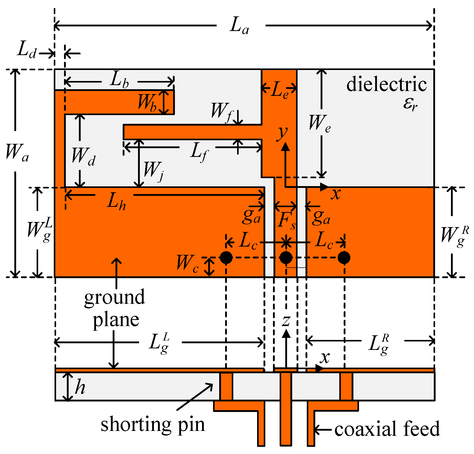
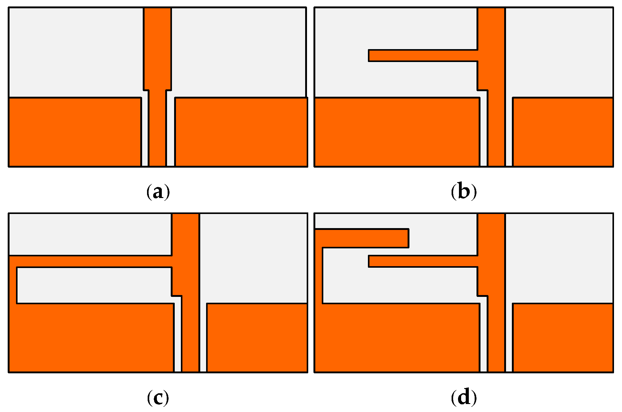
2. Antenna Design
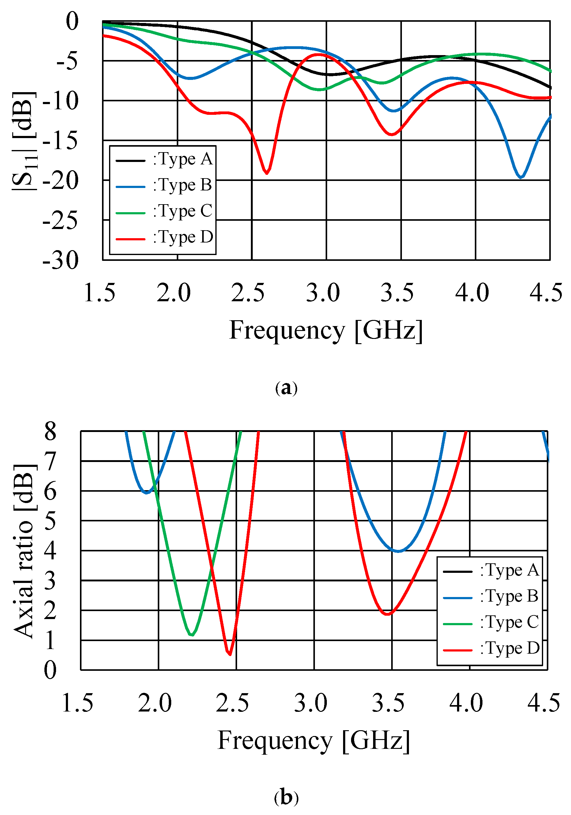
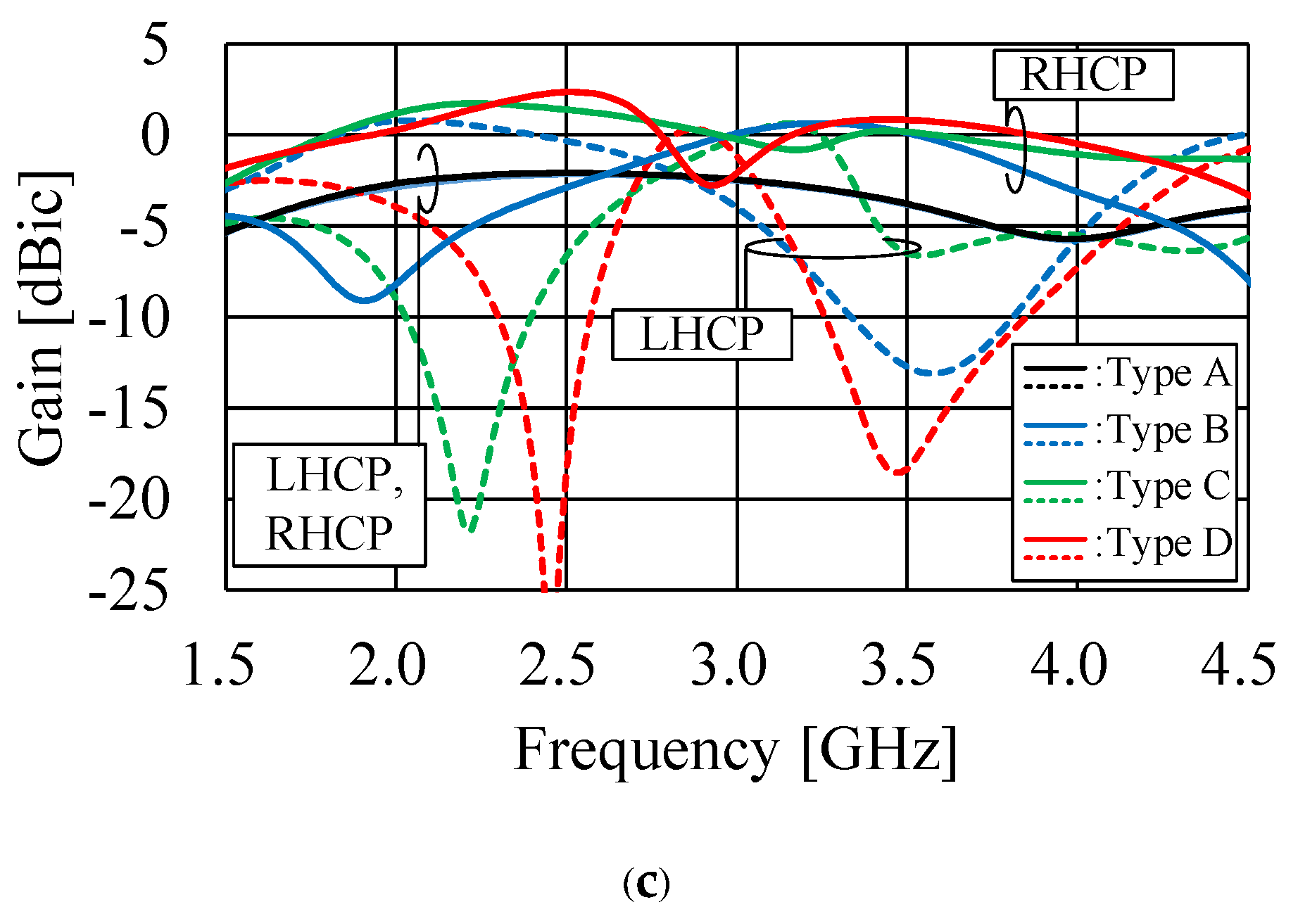
3. Antenna Characteristics
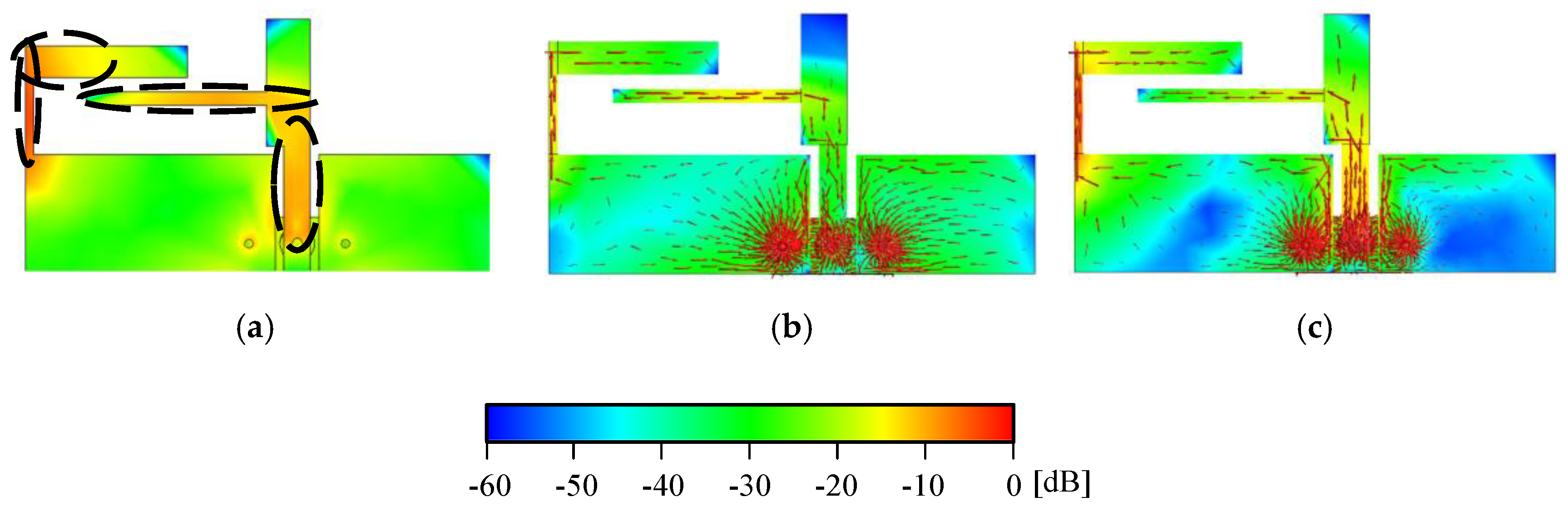
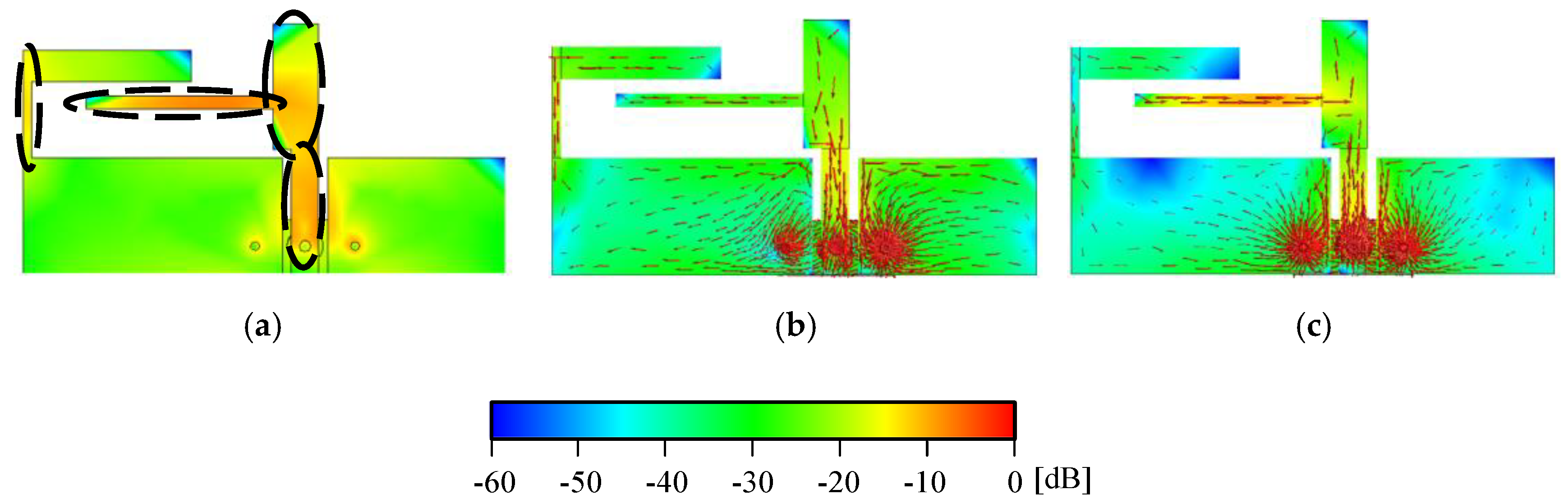
4. Operational Principles
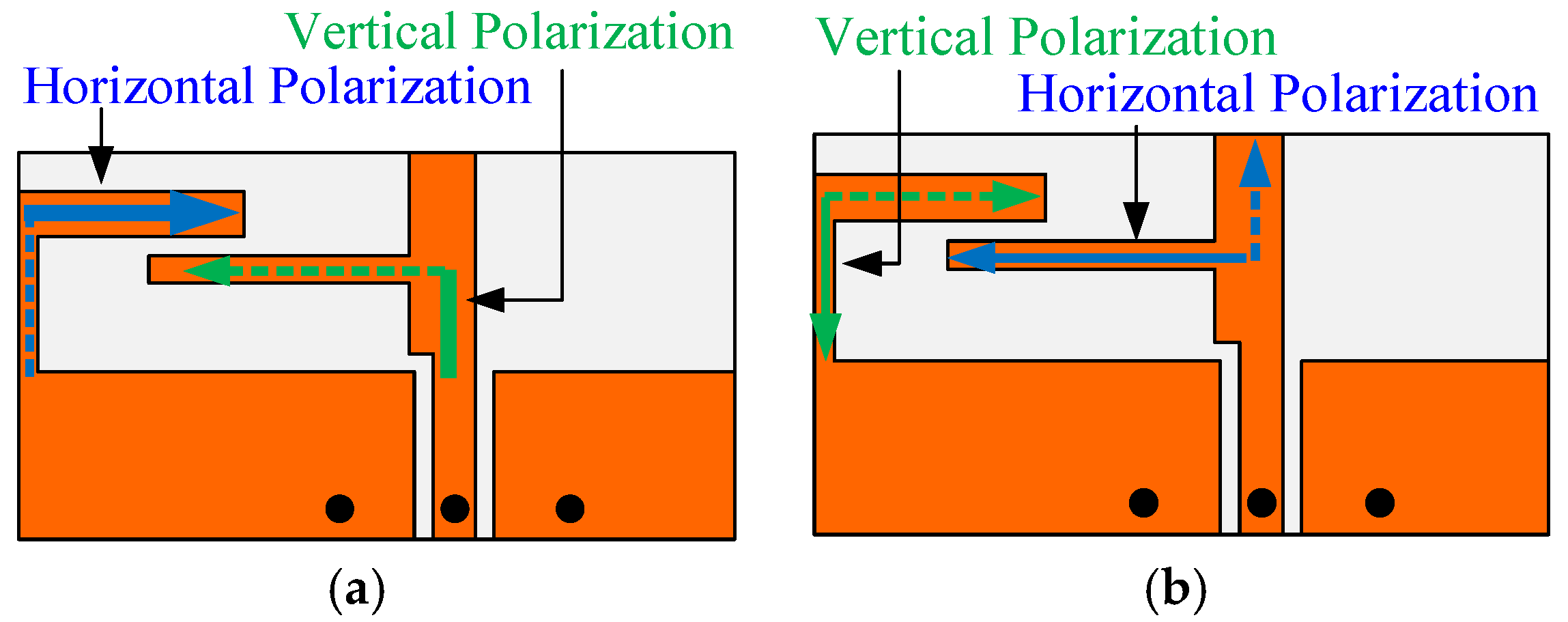
4.1. Dual-Band Single-Sense CP
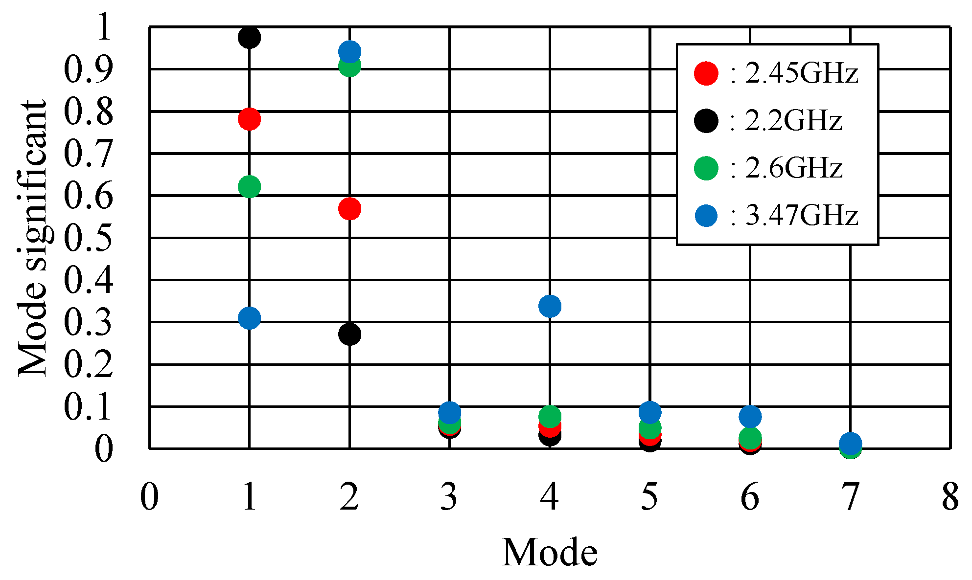
4.2. Resonant Mode of Dual Band
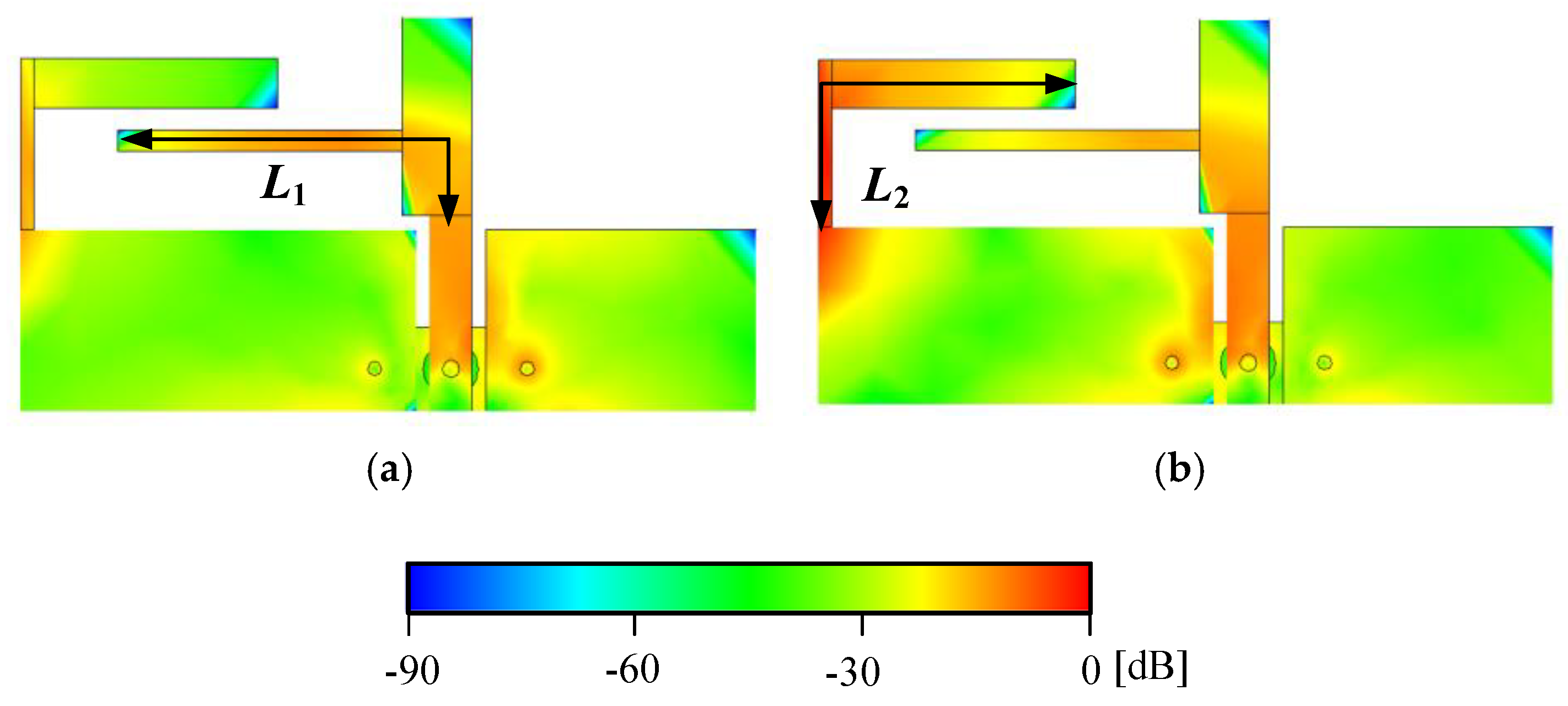
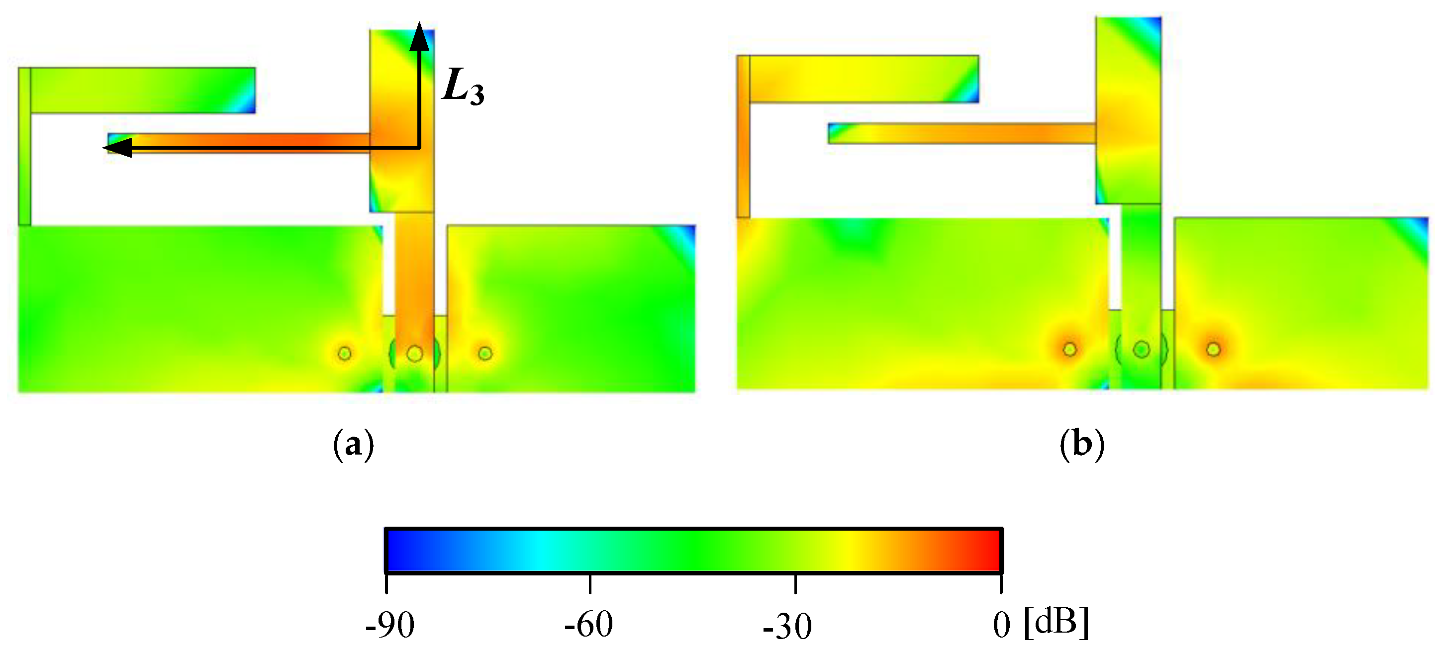
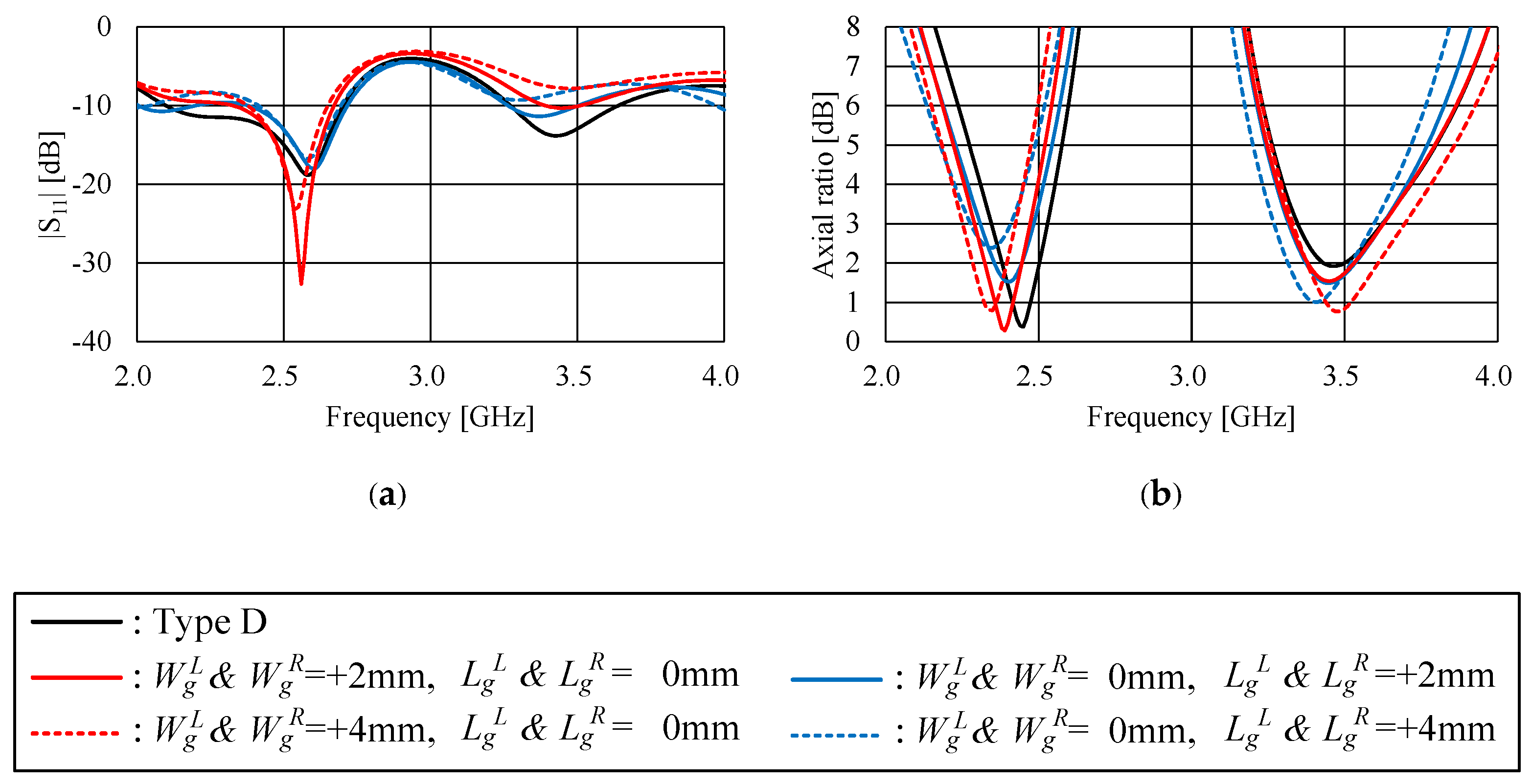
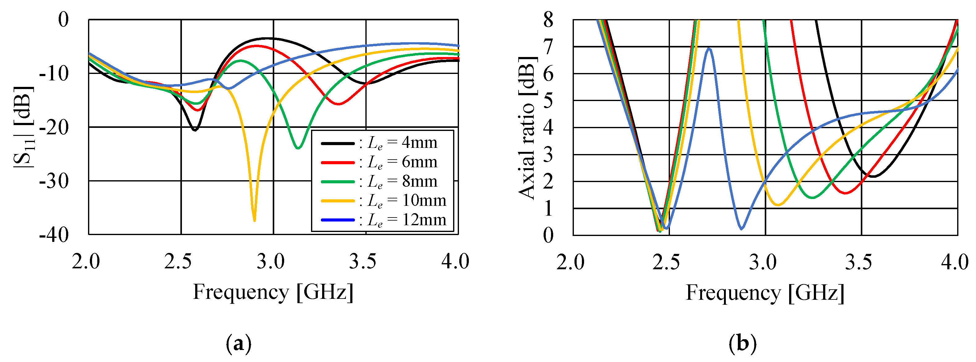
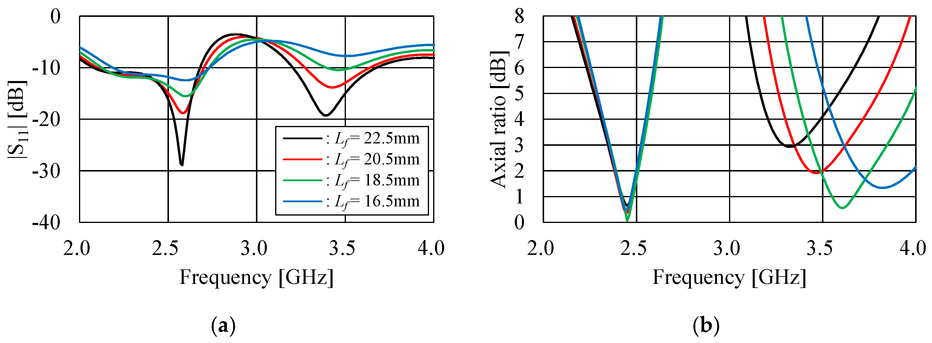
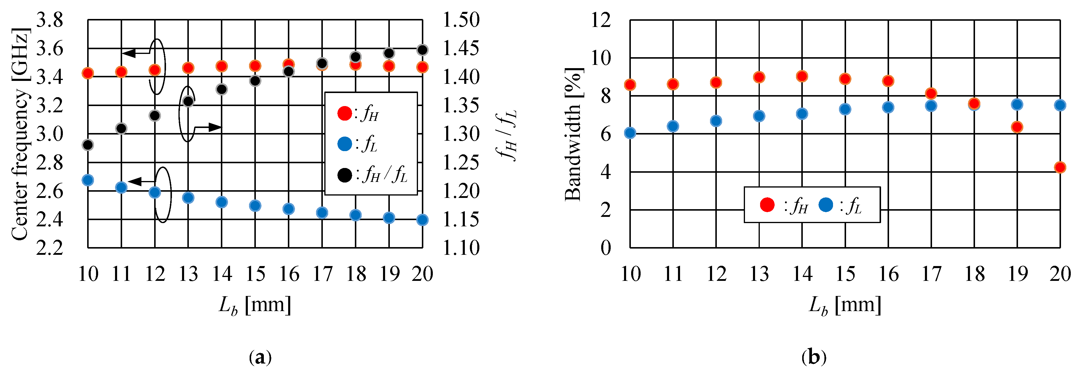
5. Parametric Studies
5.1. Ground Plane
5.2. L-Shaped and T-Shaped Elements
6. Conclusions
Author Contributions
Funding
Data Availability Statement
Conflicts of Interest
References
- Bao, X.L.; Ammann, M.J. Dual-frequency circularly-polarized patch antenna with compact size and small frequency ratio. IEEE Trans. Antenn. Propag. 2007, 55, 2104–2107. [Google Scholar] [CrossRef]
- Nasimuddin; Chen, Z.N.; Qing, X. Dual-band circularly-polarized S-shaped slotted patch antenna with a small frequency-ratio. IEEE Trans. Antenn. Propag. 2010, 58, 2112–2115. [Google Scholar]
- Sung, Y. Dual-band circularly-polarized pentagonal slot antenna. IEEE Antenn. Wireless Propag. Lett. 2011, 10, 259–261. [Google Scholar] [CrossRef]
- Chen, C.-H.; Yng, E.K.N. Dual-band circularly-polarized CPW-fed slot antenna with a small frequency ratio and wide bandwidths. IEEE Trans. Antenn. Propag. 2011, 59, 1379–1384. [Google Scholar] [CrossRef]
- Xu, Y.; Zhu, L.; Liu, N.-W. Design approach for a dual-band circularly polarized slot antenna with flexible frequency radio and similar in-band gain. IEEE Antenn. Wireless Propag. Lett. 2022, 21, 1037–1041. [Google Scholar] [CrossRef]
- Kandasamy, K.; Majumder, B.; Mukherjee, J.; Ray, K.P. Dual-band circularly polarized split ring resonators loaded square slot antenna. IEEE Trans. Antenn. Propag. 2016, 64, 3640–3645. [Google Scholar] [CrossRef]
- Yi, H.; Qu, S.-W. A Novel Dual-Band Circularly polarized antenna based on electromagnetic band-gap structure. IEEE Antenn. Wireless Propag. Lett. 2013, 12, 1149–1152. [Google Scholar] [CrossRef]
- Deng, C.; Li, Y.; Zhang, Z.; Pan, G.; Feng, Z. Dual-band circularly polarized rotated patch antenna with a parasitic circular patch loading. IEEE Antenn. Wireless Propag. Lett. 2013, 12, 492–495. [Google Scholar] [CrossRef]
- Sahana, C.; Nirmala, D.M.; Jayakumar, M. Dual-Band Circularly Polarized Annular Ring Patch Antenna for GPS-Aided GEO-Augmented Navigation Receivers. IEEE Antenn. Wireless Propag. Lett. 2022, 21, 1737–1741. [Google Scholar]
- Chen, W.-W.; Wu, Q.-S.; Zhang, X. Unified design of dual-band and triband dual-sense circularly polarized patch antennas under quad-mode operation. IEEE Antenn. Wireless Propag. Lett. 2025, 24, 1332–1336. [Google Scholar] [CrossRef]
- Liang, W.; Jiao, Y.-C.; Luan, Y.; Tian, C. A dual-band circularly polarized complementary antenna. IEEE Antenn. Wireless Propag. Lett. 2015, 14, 1153–1156. [Google Scholar] [CrossRef]
- Tan, M.-T.; Wang, B.-Z. A dual-band circularly polarized planar monopole antenna for WLAN/Wi-Fi Applications. IEEE Antenn. Wireless Propag. Lett. 2016, 15, 670–673. [Google Scholar] [CrossRef]
- Saini, R.K.; Dwari, S.; Mandal, M.K. CPW-fed dual-band dual-sense circularly polarized monopole antenna. IEEE Antenn. Wireless Propag. Lett. 2017, 16, 2497–2500. [Google Scholar] [CrossRef]
- Chen, C.; Yung, E.K.N. Dual-band dual sense circularly-polarized CPW-fed slot antenna with two spiral slots loaded. IEEE Trans. Antenn. Propag. 2009, 57, 1829–1833. [Google Scholar] [CrossRef]
- Bao, X.L.; Ammann, M.J. Monofilar spiral slot antenna for dual-frequency dual-sense circularly-polarization. IEEE Trans. Antenn. Propag. 2011, 59, 3061–3065. [Google Scholar] [CrossRef]
- Xu, R.; Li, J.-Y.; Liu, J.; Zhou, S.-G.; Wei, K.; Xing, Z.-J. A simple design of compact dual-wideband square slot antenna with dual-sense circularly polarized radiation for WLAN/Wi-Fi communications. IEEE Trans. Antenn. Propag. 2018, 66, 4884–4889. [Google Scholar] [CrossRef]
- Wu, Q.-S.; Lin, Z.-K.; Du, Z.-X.; Zhang, X. A dual-band dual-sense circularly polarized slot antenna with cascaded nonradiative resonator. IEEE Antenn. Wireless Propag. Lett. 2024, 23, 3123–3127. [Google Scholar] [CrossRef]
- Kumar, K.; Dwari, S.; Mandal, M.K. Dual-band dual-sense circularly polarized substrate integrated waveguide antenna. IEEE Antenn. Wireless Propag. Lett. 2018, 17, 521–524. [Google Scholar] [CrossRef]
- Zhao, Z.; Liu, F.; Ren, J.; Liu, Y.; Yin, Y. Dual-sense circularly polarized antenna with a dual-coupled line. IEEE Antenn. Wireless Propag. Lett. 2020, 19, 1415–1419. [Google Scholar] [CrossRef]
- Liu, N.-W.; Zhu, L.; Liu, Z.-X.; Zhang, Z.-Y.; Fu, G. Frequency-ratio reduction of a low-profile dual-band dual-circularly polarized patch antenna under triple resonance. IEEE Antenn. Wireless Propag. Lett. 2020, 19, 1689–1693. [Google Scholar] [CrossRef]
- Yang, H.; Liu, X.; Fan, Y.; Xiong, L. Dual-band textile antenna with dual circular polarizations using polarization rotation AMC for off-body communications. IEEE Trans. Antenn. Propag. 2022, 70, 4189–4199. [Google Scholar] [CrossRef]
- An, N.; Zhang, Y. Dual-band dual-sense circularly polarized antenna utilizing a radiating slot antenna as feeding structure. IEEE Antenn. Wireless Propag. Lett. 2024, 23, 1321–1325. [Google Scholar] [CrossRef]
- Fujimoto, T.; Guan, C.-E. A compact printed hybrid-mode antenna for dual-band deal-sense circular polarization. IET Microw. Antennas Propag. 2023, 17, 777–785. [Google Scholar] [CrossRef]
- Balanis, C.A. Antenna Measurements. In Antenna Theory, 3rd ed.; John Wiley & Sons, Ltd.: New York, NY, USA, 2005; pp. 1001–1048. [Google Scholar]
- Stutzman, W.L.; Thiele, G.A. Antenna Measurements. In Antenna Theory and Design, 3rd ed.; John Wiley & Sons, Ltd.: New York, NY, USA, 2012; pp. 559–586. [Google Scholar]
- Han, M.; Dou, W. Compact clock-shaped broadband circularly polarized antenna based on characteristic mode analysis. IEEE Access 2019, 7, 159952–159959. [Google Scholar] [CrossRef]
- Supreeyatitikul, N.; Lertwiriyaprapa, T.; Krairiksh, M.; Phongcharoenpanich, C. CMA-based four-element broadband circularly polarized octagonal-ring slot antenna array for S-band satellite applications. IEEE Access 2022, 10, 130825–130838. [Google Scholar] [CrossRef]


| BW (Low Band) [%] | BW (High Band) [%] | Size [λL2] | Size [λH2] | fH/fL | Gain (Low Band) [dBic] | Gain (High Band) [dBic] | Single/Dual (Sense) | |
|---|---|---|---|---|---|---|---|---|
| [1] | 0.98 | 1.08 | 0.06 | 0.087 | 1.21 | 1.35 | 3.5 | single |
| [2] | 6.87 | 0.57 | 0.221 | 0.365 | 1.27 | single | ||
| [3] | 7.13 | 3.25 | 1.440 | 8.649 | 2.45 | 3.7 | 3.2 | single |
| [4] | 9.09 | 11.11 | 0.129 | 0.213 | 1.29 | 2.5–4 | single | |
| [5] | 2.84 | 2.10 | 0.754 | 2.599 | 1.86 | 4.79 | 4.27 | single |
| [5] | 3.88 | 1.38 | 0.805 | 1.309 | 1.28 | 4.47 | 4.23 | single |
| [23] | 7.32 | 9.04 | 0.0741 | 0.151 | 1.44 | 1.5 | 5.2 | dual |
| This work | 5.30 | 9.90 | 0.100 | 0.208 | 1.44 | 3.3 | 2.4 | single |
| Min. AR [dB] | Freq. [GHz] | [dB] | [°] | |
|---|---|---|---|---|
| Type B | 5.92 | 1.92 | 4.66 (−7.64, −12.3) | −67 (118.0, −175.0) |
| Proposed (Type D) | 0.44 | 2.45 | 0.35 (−2.77, −3.12) | 87.7 (−85.3, −173.0) |
| Min. AR [dB] | Freq. [GHz] | [dB] | [°] | |
|---|---|---|---|---|
| Type B | 3.97 | 3.54 | 3.05 (−3.63, −6.68) | 77.0 (178.0, 101.0) |
| Proposed (Type D) | 1.85 | 3.47 | 1.11 (−3.22, −4.33) | 78.5 (177.0, 98.50) |
| Mode 1 | Mode 2 | Mode 3 | Mode 4 | |
|---|---|---|---|---|
| 2.45 GHz | 142.54° −37.46° | 234.37° 54.37° | 93.32° −86.68° | 266.93° 86.93° |
| 3.47 GHz | 108.21° −71.79° | 167.32° −12.68° | 94.92° −85.08° | 250.15° 70.15° |
Disclaimer/Publisher’s Note: The statements, opinions and data contained in all publications are solely those of the individual author(s) and contributor(s) and not of MDPI and/or the editor(s). MDPI and/or the editor(s) disclaim responsibility for any injury to people or property resulting from any ideas, methods, instructions or products referred to in the content. |
© 2025 by the authors. Licensee MDPI, Basel, Switzerland. This article is an open access article distributed under the terms and conditions of the Creative Commons Attribution (CC BY) license (https://creativecommons.org/licenses/by/4.0/).
Share and Cite
Fujimoto, T.; Guan, C.-E. A Printed Hybrid-Mode Antenna for Dual-Band Circular Polarization with Flexible Frequency Ratio. Electronics 2025, 14, 2504. https://doi.org/10.3390/electronics14132504
Fujimoto T, Guan C-E. A Printed Hybrid-Mode Antenna for Dual-Band Circular Polarization with Flexible Frequency Ratio. Electronics. 2025; 14(13):2504. https://doi.org/10.3390/electronics14132504
Chicago/Turabian StyleFujimoto, Takafumi, and Chai-Eu Guan. 2025. "A Printed Hybrid-Mode Antenna for Dual-Band Circular Polarization with Flexible Frequency Ratio" Electronics 14, no. 13: 2504. https://doi.org/10.3390/electronics14132504
APA StyleFujimoto, T., & Guan, C.-E. (2025). A Printed Hybrid-Mode Antenna for Dual-Band Circular Polarization with Flexible Frequency Ratio. Electronics, 14(13), 2504. https://doi.org/10.3390/electronics14132504