Article

Enhancing Grid Strength in High-Renewable Systems: Selecting Retired Thermal Power Units Retrofit to Synchronous Condensers Based on Multi-Dimensional Evaluation Method

1
Northeast Branch of State Grid Corporation of China, Shenyang 110170, China
2
Department of Electric Power Engineering, North China Electric Power University, Baoding 071003, China
*
Author to whom correspondence should be addressed.
Electronics 2025, 14(12), 2467; https://doi.org/10.3390/electronics14122467
Submission received: 16 May 2025 / Revised: 14 June 2025 / Accepted: 16 June 2025 / Published: 18 June 2025

Abstract

With the rapid development of renewable energy in China, thermal power units are facing decommissioning issues, while the power system is confronted with severe challenges such as reduced grid strength and insufficient voltage support. For power systems with multiple renewable energy stations, the short-circuit ratio at the connection points of renewable energy stations is an important indicator for measuring grid strength. Engineering requirements specify that the short-circuit ratio at these connection points should not be lower than 2.0. This study focuses on transforming retired thermal power units into synchronous condensers to improve the short-circuit ratio at renewable energy station connection points. This paper first studies the impact of thermal power unit operation, shutdown, and synchronous phasor operation on the short-circuit ratio, deriving the short-circuit ratio expressions for renewable energy stations under different states of thermal power units. It further analyzes the impact of different main transformer capacities and unit transformation capacities on the short-circuit ratio. Next, a multi-dimensional evaluation system is constructed, incorporating the change in short-circuit ratio at grid-connection points of multiple renewable energy stations ( Δ M R S C R S ), the main transformer capacity within short-circuit ratio enhancement range ( S T ), the pre-retrofit short-circuit ratio level at grid-connection points of multiple renewable energy stations ( S G ), and the retrofitted unit capacity ( M R S C R S ) to comprehensively assess the transformed thermal power units. Finally, a case analysis conducted on the modified IEEE-39 bus system using the PSASP platform verifies that operating thermal power units as synchronous condensers can significantly enhance the short-circuit ratios of multiple renewable energy sites. Given that small-capacity thermal units are approaching retirement, there is a stronger preference for retrofitting these smaller units as synchronous condensers. The multi-dimensional evaluation method proposed in this study specifically identifies small-capacity thermal units as the most suitable candidates for such retrofitting. This approach provides theoretical support for implementing synchronous condenser operation in retired thermal power units and promotes the coordinated optimization of grid security and renewable energy integration.

1. Introduction

With the transformation of the global energy structure and the promotion of “double carbon” goals, the installed capacity of new energy systems continues to increase, and power systems are undergoing a profound change from synchronous machine-dominated to power electronic equipment-dominated. With the large-scale grid connection of new energy sources, represented by wind power and photovoltaic systems, as well as the gradual retirement of traditional thermal power units, the power grid exhibits the “double-high” characteristics of a “high proportion of new energy and high-power electrification” [1,2]. In this context, advancing the retrofitting, upgrading, and functional role transformation of China’s thermal power units in a coordinated manner is an essential task for achieving the “double carbon” goals and accelerating the construction of a new power system [3,4,5]. While this shift enhances the share of clean energy, it also poses significant challenges to the power grid, including insufficient renewable energy accommodation, weakened voltage support, and reduced grid strength.
Increasing the reactive power supply can improve the voltage support capacity of the grid. Commonly used suppliers of reactive power include power capacitors, static var compensators (SVCs), static var generators (SVGs), and synchronous condenser. Garrido, C and Falaghi, H mention that capacitors and SVCs have a weak reactive power output capacity at low voltages and cannot effectively meet the compensation demand [6,7]. Sun, Y mentions that SVGs tend to introduce harmonics, are more complex to maintain, and have a limited range of reactive power compensation [8]. Wang, Y mentions that high-capacity synchronous condensers have a strong reactive power regulation capability, high stability, and are suitable for long-distance transmission systems, but they are also bulky, slow to start, and have high investment and maintenance costs [9]. Suo et al. mentions that distributed synchronous condensers have the advantages of superior transient dynamic characteristics, high security, stability, and short-time overload capacity, and are easy to operate and maintain, but their adaptability to large power grids is poor, and they are costly to install [10,11,12,13,14,15,16]. As the proportion of new energy continues to rise, the stock of conventional thermal power units has been steadily decreasing. In response, policy measures are actively promoting the decommissioning of non-heating units below 300 MW and encouraging residential heating and industrial power consumption to be concentrated in large-scale units of 600 MW and above, thereby creating conditions for the subsequent reuse of retired units. The “Opinions on Improving the Mechanisms and Policy Measures for Green and Low-Carbon Energy Transition”, issued by the National Development and Reform Commission and the National Energy Administration in January 2022, explicitly states that existing sites and supporting facilities of decommissioned thermal power plants may be repurposed into new energy storage facilities or synchronous condensers [17]. Subsequently, in 2023, the Central China Energy Regulatory Office of the National Energy Administration revised the “Detailed Rules for the Management of Auxiliary Services in Power Plants and Grid-Connected Operation”, further refining both the compensation methods and technical standards for conversion to synchronous condensers. These updates provide solid policy and economic support for thermal power units transitioning to synchronous condenser operation [18]. Existing research [19,20,21] indicates that retrofitting decommissioned thermal units as synchronous condensers can supply reliable dynamic reactive power support to the grid while being more cost-effective than installing new synchronous condensers. However, there remains a lack of systematic, scientific evaluation of the grid-support effectiveness of such converted units.
In traditional power grids dominated by synchronous machines, the amount of change in the short-circuit ratio has been widely used to evaluate grid strength due to its simple expression and clear physical meaning [22]. However, with the integration of multiple high-voltage direct current (HVDC) systems and large-scale penetration of renewable energy, the multi-infeed and multi-terminal characteristics of modern grids have significantly enhanced reactive coupling effects among power sources, making the single short-circuit ratio index inadequate for accurately reflecting actual voltage stability. To address this, the international council on large electric systems (CIGRE) proposed the multi-infeed short-circuit ratio (MISCR) concept based on Thevenin equivalent networks and node impedance matrix theory. MISCR incorporates interactive effects between different infeed into traditional short-circuit capacity assessment, demonstrating that the conventional short-circuit ratio represents a special limiting case of MISCR, while establishing more appropriate grid strength classification criteria for multi-HVDC scenarios [23,24]. When wind and photovoltaic resources become dominant grid-connected generation units, their fault current characteristics—constrained by current-limiting mechanisms, dynamic reactive power regulation, and distributed connection modes—make even MISCR insufficient for fully characterizing grid strength in renewable-rich systems. In Reference [25], Xin, H proposed a generalized short-circuit ratio index based on a decoupling method, which further clarifies the physical mechanism of traditional DC short-circuit ratio in multi-infeed scenarios. In Reference [26], Wang, S proposed an analysis method based on the equivalent impedance approach and the influence factor method to investigate the variation patterns of the multi-infeed short-circuit ratio (MISCR) with increasing DC infeed loops. It further dissected the fundamental reasons why some existing literature mistakenly assumed that the MISCR could exceed the single-infeed short-circuit ratio. Addressing this, in Reference [27], Sun, H mentions that enhanced the MISCR framework by considering voltage magnitude/phase differences between nodes and incorporating the impedance relationships among renewable energy stations, thereby proposing the multiple renewable energy station short-circuit ratio (MRSCR). This metric preserves MISCR’s multi-infeed interaction analysis while capturing distributed renewable stations’ phase coupling and reactive support characteristics during faults. When specific impedance types and phase conditions satisfy certain approximations, MRSCR naturally degenerates to conventional MISCR, maintaining mathematical consistency between old and new indices. Current grid strength evaluation primarily relies on single short-circuit ratio indices, but the mere variation of MRSCR still fails to accurately reflect the enhancement effects of synchronous generator phase modulation on grid strength. Therefore, there is urgent need to develop more comprehensive evaluation metrics for the holistic assessment of these impacts.
In traditional power system research, various evaluation methods have been proposed to analyze grid strength and stability under different operating conditions. With the large-scale integration of high-penetration renewable energy, system operation complexity has increased significantly, and a single metric is no longer sufficient for comprehensive grid assessment. Consequently, multi-dimensional comprehensive evaluation approaches have gradually attracted widespread attention. Reference [28] improves the Analytic Hierarchy Process (AHP) to perform multi-level quantification of voltage sag severity, achieving a refined assessment of voltage quality issues. Reference [29] combines AHP with trapezoidal fuzzy complementary judgment matrices to reduce subjectivity in evaluation and enhance consistency. Reference [30] applies the entropy weight method to objectively assign weights to grid flexibility indicators across different operating scenarios, providing a scientific basis for indicator weight allocation. Reference [31] introduces multiple rounds of expert scoring combined with relative importance ranking of indicators to assess the demand for auxiliary energy storage in renewable power plant retrofits. Although these methods have achieved significant results in their respective areas, existing research on integrating subjective and objective weights remains insufficient, often biased toward a single dimension and thus unable to balance subjectivity and objectivity adequately. Moreover, there is still a lack of systematic evaluation of the effect that operating synchronous condensers—converted from retired thermal power units—has on grid strength. In view of this gap, the present paper aims to construct a multi-dimensional evaluation method that accommodates both subjective and objective weights to quantitatively assess the gain in grid strength resulting from converting retired thermal power units into synchronous condensers, thereby providing theoretical support for retrofitting thermal units to synchronous condenser operation and for the large-scale integration of renewable energy.
This study focuses on the problems of weakened grid strength and insufficient voltage support capacity in the context of a high proportion of new energy grid-connectedness, examines the synchronous condenser operation of thermal power units in the new energy aggregation area, and proposes a multi-dimensional evaluation method to evaluate its enhancement effect. First, a mathematical model is constructed for the enhancement of the MRSCR via the synchronous condenser operation of thermal power units to quantify the regulation mechanism of self and mutual impedance. Second, three indicators are proposed to establish an evaluation index for the synchronous condenser operation of thermal power units: multiple renewable energy station short-circuit ratio improvement, unit modification capacity, and main transformer capacity. Finally, a multi-scenario examples of the IEEE-39 node system is carried out based on the PSASP platform to verify the effectiveness of the proposed model in improving the short-circuit ratio and the strength of the grid, providing a theoretical basis and an engineering reference for planning a new energy grid with a high percentage of new energy and retrofitted retired units.

2. Effect of Synchronous Condenser Operation of Thermal Power Units on Short-Circuit Ratio

2.1. Definition of Short-Circuit Ratio

The short-circuit ratio can be used to measure the strength of a new energy power system grid, providing an important reference for grid planning and layout, electrical equipment capacity selection, and so on [32,33,34,35,36]. For a new energy field station connected to the AC system, the short-circuit ratio of the new energy station’s grid-connected points is defined as the new energy field station grid point three-phase short-circuit capacity and new energy electrical equipment injected active power ratio, as shown in Equation (1):
S C R = S ac P N = 1 Z pu
where SCR represents the short-circuit ratio of the new energy station grid-connected points; S ac represents the three-phase short-circuit capacity of the AC system; P N represents the new energy electrical equipment injected active power; and Z pu represents the per-unit value of the system impedance. Per-unit value is obtained by dividing an electrical quantity by its base value, which is a standardized method used in power system analysis. In this study, the base voltage is set at 220 kV, and the system base power is established as 100 MVA.

2.2. Impact of Thermal Units on Short-Circuit Ratio

The short-circuit capacity of the grid point of the new energy field station is the apparent power at the short-circuit point when a three-phase short circuit occurs at the node. It is a parameter that characterizes the strength of the power system’s power supply capacity. Numerically, it is equal to the product of the short-circuit current and rated voltage at the short-circuit point when a three-phase short circuit occurs at the grid-connected points of the new energy field station.

2.2.1. Short-Circuit Ratio of New Energy Field Station During Thermal Power Unit Power Generation Operation

For a simple power system containing a new energy field station and a thermal power unit, a diagram is shown in Figure 1.
In this figure, S RE 1 , P RE 1 , and Q RE 1 are the complex power, active power, and reactive power output from the new energy station; U RE i is the rated voltage of the grid-connected bus of the new energy station; Z T 1 and Z T 2 are the impedance of the step-up transformer of the new energy station; Z T 3 is the impedance of the transformer of the new energy gathering station; Z T 4 is the impedance of the step-up transformer of the thermal power field; Z 1 and Z 2 are the impedance of the transmission line; Z S is the equivalent impedance of the system; and Z G is the equivalent impedance of the thermal power unit.
When a three-phase short circuit occurs at the new energy field station grid point i, the short-circuit capacity of the new energy grid point is shown in Equation (2):
S ac i = U RE i I k = U RE i 2 ( Z T 1 + Z T 2 ) / / ( Z 1 + Z T 3 + ( Z S / / ( Z 2 + Z T 4 + Z G ) ) )
Considering the coupling relationship between the thermal power unit and the new energy field station, a short-circuit ratio at point i of the new energy grid connection is shown in Equation (3).
S C R S , i = S ac i P RE 1 + Z i j Z i i P 1
where Z i i is the self-impedance of node i, and Z i j is the mutual impedance of node i and node j.

2.2.2. Short-Circuit Ratio of New Energy Field Station After Thermal Power Unit Shuts Down

When the thermal power unit is shut down, the simple power system shown in Figure 1 becomes the system shown in Figure 2.
The short-circuit capacity of the new energy grid point i can be expressed as follows:
S ac i = U RE i I k = U RE i 2 ( Z T 1 + Z T 2 ) / / ( Z 1 + Z T 3 + Z S )
The short-circuit ratio at the grid-connected point i of the new energy field station is shown in Equation (5):
S C R S , i = S ac i P RE 1
where P RE 1 is the output power of the new energy field station after the shutdown of the thermal power unit. Assuming that the load and the power fed into the grid remain unchanged, the output power of the wind farm increases after the thermal power generator is shut down; the output power of the wind farm should be equal to the output power of the wind farm before the shutdown and the sum of the output power of the thermal power plant, that is, P RE 1 = P RE 1 + P 1 .
Comparing Equations (2) and (4), it can be seen that the short-circuit capacity S ac i of the grid-connected point decreases after the shutdown of the thermal power unit; comparing Equations (3) and (5), the denominator of Equation (5) is larger than the denominator of Equation (3) because the self-impedance is generally larger than the mutual impedance. For a thermal power unit with a larger capacity, the increase in the denominator of Equation (5) is larger than that of the numerator, and the short-circuit ratio of the grid-connected points of the new energy station decreases after the shutdown of the thermal power unit.

2.2.3. Short-Circuit Ratio of New Energy Field Station During Synchronous Condenser Operation of Thermal Power Unit

When the thermal power unit is retrofitted for synchronous condenser operation, Figure 1 becomes Figure 3.
The short-circuit capacity of the new energy field station i after being retrofitted to a synchronous condenser is shown in Equation (6):
S ac i = U RE i I k = U RE i 2 ( Z T 1 + Z T 2 ) / / ( Z 1 + Z T 3 + ( Z S / / ( Z 2 + Z T 4 + Z p ) ) )
where Z P is the equivalent impedance of the thermal power unit during synchronous condenser operation. According to the requirements of the standard DL/T2658-2023 [37], “Technical specification for fast dynamic response synchronous regulator”, the d-axis sub-transient reactance X d of the synchronous condenser should not be greater than 0.14, and the d-axis sub-transient reactance X d of the thermal power unit with the model number of SF300-44/12440 is 0.2205. Therefore, comparing Equations (2) and (6), the short-circuit capacity of the thermal power unit after synchronous condenser operation is initiated is larger than the short-circuit capacity of a thermal power unit during power generation.
The short-circuit ratio at the grid-connected point i of the new energy field station is shown below:
S C R S , i = S ac i P RE 1
A comparison of Equations (2), (4), and (6) shows that the short-circuit capacity at the grid-connected point of the thermal power unit is the largest when it is operating in synchronous condenser mode. The denominator of Equation (7) is the same as that of Equation (5), so the short-circuit ratio of the grid-connected point of the new energy field station is larger than that of the thermal power unit when it is operating in synchronous condenser mode.
The relationship between the short-circuit ratio at the generator terminal of a new energy power plant ( S C R G ) and the short-circuit ratio at the grid-connection point of the plant ( S C R S ) under unit voltage is given by the following equation [8].
1 S C R S = 1 S C R G + Z T 1 + Z T 2

2.3. Impact of Main Transformer Capacity and Unit Modification Capacity of Aggregation Station on Short-Circuit Ratio

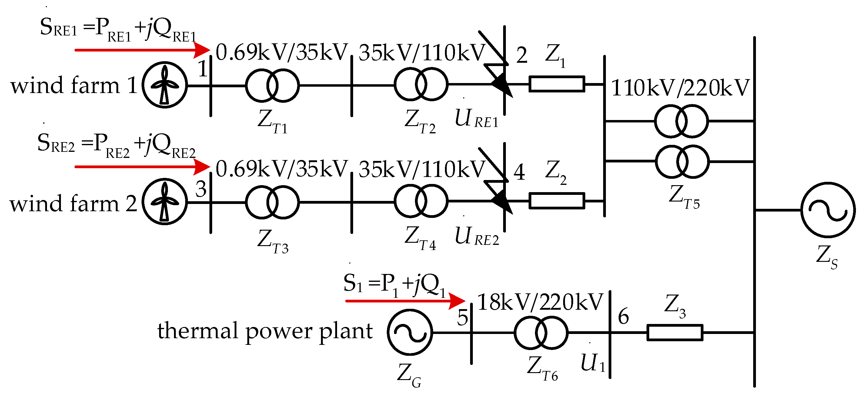
This study further considers a scenario in which multiple new energy field stations are connected to the same aggregation station, which has two main transformers and is connected to the same network as thermal power units, as shown in Figure 4.
In Figure 4, S RE i , P RE i , Q RE i , and U RE i (i = 1, 2) are the complex power, active power, reactive power, and grid-connected bus voltage output from the new energy station i; S 1 , P 1 , Q 1 , and U 1 are the complex power, active power, reactive power, and grid-connected bus voltage output from the thermal power plant; Z i (i = 1, 2, 3) are the output line impedance, Z T i (i = 1, 2, 3, 4, 5, 6) are the transformer impedance, of which Z T 5 is the main transformer impedance of the new energy aggregation station; and Z F 1 and Z F 2 are the equivalent impedances of the wind farms.
Taking wind farm 1 as an example, when the thermal power unit is generating electricity for operation, the short-circuit ratio at the grid-connected point of this new energy field station, i.e., node 2, can be expressed as follows:
M R S C R S , 2 = S ac 2 P RE 1 + Z eq 24 Z eq 22 P RE 2 + Z eq 26 Z eq 22 P 1 = U N 2 2 / ( Z T 1 + Z T 2 ) / / ( Z + Z 1 ) P RE 1 + Z eq 24 Z eq 22 P RE 2 + Z eq 26 Z eq 22 P 1
where Z = Z + Z T 5 / 2 / / Z F 2 + Z T 3 + Z T 4 + Z 2 ; Z = Z S / / Z G + Z T 6 + Z 3 ; Z eq 22 , Z eq 24 , and Z eq 26 are the self-impedance of node 2, the mutual impedance of nodes 2 and 4, and the mutual impedance of nodes 2 and 6, respectively, during the power generation operation of the thermal power unit.
The short-circuit ratio example at the grid-connected point of wind farm 1 when the thermal unit is operating in synchronous condenser is shown in Equation (10):
M R S C R S , 2 = S ac 2 P RE 1 + Z eq 24 Z eq 22 P RE 2 = U N 2 2 / ( Z T 1 + Z T 2 ) / / ( Z P + Z 1 ) P RE 1 + Z eq 24 Z eq 22 P RE 2
where Z P = Z P + Z T 5 / 2 / / Z F 2 + Z T 3 + Z T 4 + Z 2 ; Z P = Z S / / Z P + Z T 6 + Z 3 ; Z e q 22 , Z e q 24 are the self-impedance of node 2 and the mutual impedance of nodes 2 and 4, respectively, during the synchronous condenser operation of the thermal power unit.

2.3.1. Influence of the Main Transformer Capacity of a Pooling Station on the Short-Circuit Ratio

The impedance of the main transformer of the wind farm pooling station can be expressed as follows:
Z T 5 = R T 5 + j X T 5 = P k U N 2 1000 S TN 5 2 + j U k % U N 2 100 S TN 5
where S TN 5 is the rated capacity of the main transformer of the converging station. With an increase in the capacity of the main transformer, the Z T 5 impedance will decrease accordingly.
When the thermal power unit generates electricity, substituting Equation (11) into Equation (9) shows that as the impedance Z T 5 of the main transformer of the converging station decreases, Z” decreases, and the molecule of Equation (9) increases. The short-circuit ratio of the new energy field station and grid point increases in the scenario in which the new energy field station’s output power remains unchanged. Similarly, according to Equation (10), the short-circuit ratio of the grid point of the new energy field station increases with decreases in Z T 5 and Z” during the synchronous condenser operation of thermal power units.
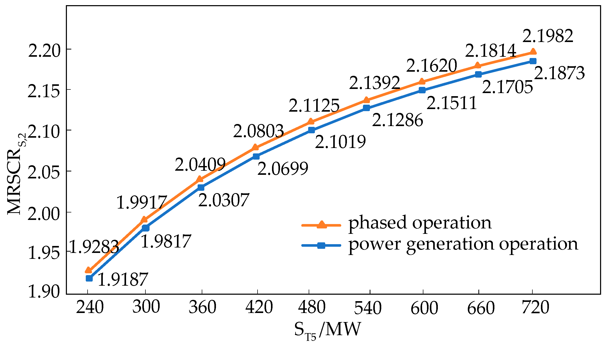
According to Equations (9) and (10), the short-circuit ratio of wind farm 1’s grid-connected point is calculated and plotted with the trend of the new energy pooling station’s main transformer capacity, S T 5 , as shown in Figure 5.
As shown in Figure 5, regardless of if the thermal power unit is operating in power generation or synchronous condenser operation mode, the MRSCR increases as the main transformer capacity of the pooling station increases. Therefore, the main transformer capacity of the aggregation station indirectly affects the MRSCR.

2.3.2. Influence of Synchronous Condenser Operation Thermal Unit Capacity on Short-Circuit Ratio

The impedance of a thermal power unit can be expressed as follows:
Z G = j X G = j X d U GN 2 S GN
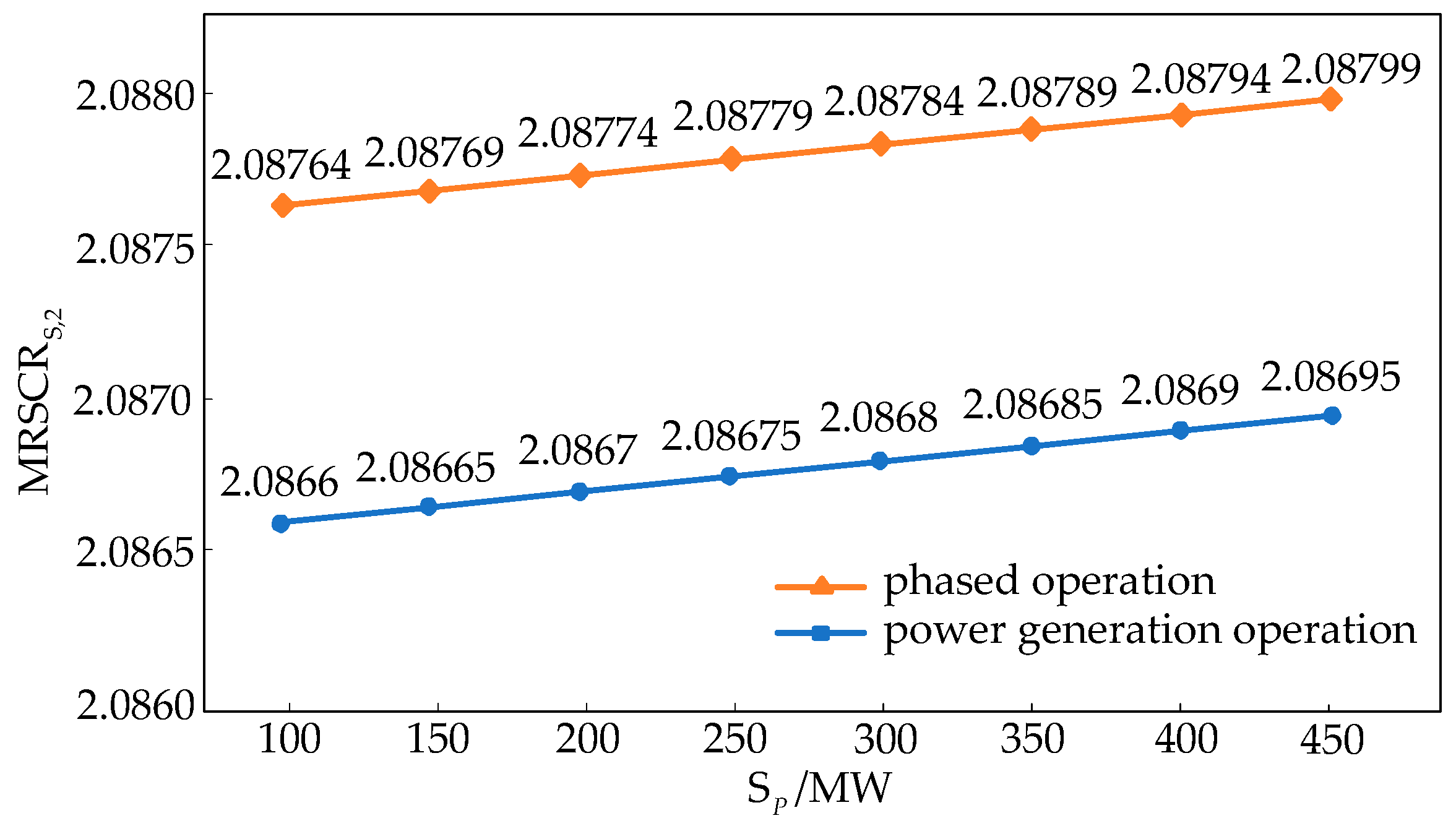
where S GN is the rated capacity of the thermal power unit. The larger the rated capacity of the thermal power unit, the smaller the impedance of Z G . Similarly, the equivalent impedance Z P of the thermal power unit during synchronous condenser operation is also smaller. According to Equation (9), as the capacity of thermal power unit increases, Z G decreases; Z and Z subsequently decrease, so the numerator of Equation (9) increases, and the short-circuit ratio of the grid-connected points of the new energy field station increases. Similarly, when the thermal power unit is running in synchronous condenser operation mode, as the capacity of the modified unit increases, the short-circuit ratio of the grid-connected points of the new energy field station also increases. According to Equations (9) and (10), the short-circuit ratio at the grid-connected points of wind farm 1 are calculated for different thermal unit capacities for power generation and synchronous condenser operation, as shown in Figure 6. As seen in Figure 6, the short-circuit ratio at the new energy grid-connected point increases with the increase in unit capacity, which verifies the previous theoretical analysis.
As shown in Figure 6, the MRSCR increases with the capacity expansion of retrofitted units, regardless of whether thermal power units operate in generation mode or synchronous condenser mode. Thus, the capacity of retrofitted units indirectly influences the MRSCR, which verifies the previous theoretical analysis.

3. Evaluation Index System for Synchronous Condenser Operation of Thermal Power Units

The conversion of thermal power units to synchronous condenser operation can improve the short-circuit ratio of new energy field stations and improve the voltage support capacity. From the analysis in the previous section, it can be seen that the capacity of the main transformer of the new energy pooling station and the capacity of the thermal power units will indirectly affect the short-circuit ratio of the grid-connected points of the new energy field station. In addition, the short-circuit ratio of the new energy field station before transformation will directly affect the necessity of operating thermal power units in synchronous condenser mode. Therefore, in order to comprehensively assess this necessity, this study proposes four evaluation indexes: the change in short-circuit ratio at grid-connection points of multiple renewable energy stations ( Δ M R S C R S ), the main transformer capacity within short-circuit ratio enhancement range ( S T ), the pre-retrofit short-circuit ratio level at grid-connection points of multiple renewable energy stations ( S G ), and the retrofitted unit capacity ( M R S C R S ). Based on these four indicators, this study carried out a comprehensive assessment by scientifically assigning weights and adopting the combination assignment method to ensure an objective and fair reflection of the improvement in grid strength after the transformation [38,39,40,41].
At present, the determination of weights can be divided into subjective or objective. In order to respond to the relative importance of the indicators more scientifically, this study combined the subjective and objective weights of the assessment indicators for the calculation of weights. Subjective and objective weights were determined using hierarchical analysis and entropy weighting methods, respectively. The overall goal was to minimize the deviation of the evaluation results, as shown in Equation (13):
min F = i = 1 m j = 1 n { [ ( u j w j ) f i j ] 2 + [ ( v j w j ) f i j ] 2 } s . t . i = 1 n w j = 1 , 0 < w j < 1
where w j is the portfolio weight, u j is the subjective weight, v j is the objective weight, and f i j is the Z-score normalized evaluation matrix element.
The combination weights that take into account both subjective and objective situations can be obtained by using the least squares solution. A Lagrangian function, as shown in Equation (14), is established:
L ( w j , λ ) = λ j = 1 n w j 1 + i = 1 m j = 1 n { [ ( u j w j ) f i j ] 2 + [ ( v j w j ) f i j ] 2 }
where L ( w j , λ ) is the Lagrangian function, and λ is the Lagrangian multiplier.
Solving for the variables w j and λ in Equation (14) by taking the partial derivatives and making them 0 gives the following Equation (15):
L w j = λ 2 i = 1 m u j w j f i j 2 + v j w j f i j 2 = 0 L λ = i = 1 n w j 1 = 0
Equation (15) can be written in matrix form, as shown in Equation (16):
C e e T 0 W λ = D 1
where e = [ 1 , 1 , , 1 ] T , W = [ w 1 , w 2 , , w n ] T , C = d i a g i = 1 m 4 f 1 i 2 , i = 1 m 4 f 2 i 2 , , i = 1 m 4 f n i 2 , and D = 2 u 1 + v 1 i = 1 m f 1 i 2 , u 2 + v 2 i = 1 m f 2 i 2 , , u n + v n i = 1 m f n i 2 T .
Solving the above equation gives the following result:
W = C 1 D e λ
where λ = e T C 1 D 1 e T C 1 e .
According to the calculation of Equation (17), the matrix W can be obtained, which is the combined weight obtained by combining subjective weights and objective weights. This weight allocation reflects the relative importance of each indicator, and after considering the combined weights of each indicator, the multi-dimensional evaluation of synchronous condenser operation of thermal power units improves the effect, as shown in Equation (18), written as follows:
F = w 1 × Δ M R S C R S + w 2 × S T + w 3 × M R S C R S + w 4 × S G

4. Case Study

The IEEE-39 node system is a classic test system in power system research, and this study builds an improved IEEE-39 node system based on the PSASP platform (This study uses version 7.0 of the PSASP software, which is developed and provided by the China Electric Power Research Institute). The wind farms are accessed at nodes 3, 15, and 17, and the total capacity of the wind farms is 1024 MW, 840 MW, and 600 MW, respectively. The improved IEEE-39 node system is shown in Figure 7.

4.1. Impact of Thermal Power Unit Shutdown or Synchronous Condenser Operation on Short-Circuit Ratio of New Energy Stations

Considering a certain margin, the short-circuit ratio of the new energy machine end should be more than 1.5, and the short-circuit ratio of the parallel network point of the new energy field station should be 2.0~2.5. For the thermal power units at nodes 30, 32, 33, 35, 36, and 37, the two modes of shutdown and synchronous condenser operation are considered, respectively, and the short-circuit ratio of the new energy field station machine end and grid-connected points are calculated for different power outputs of the wind farm, where the short-circuit ratio for generator shutdown or synchronous condenser operation at node 30 are shown in Table 1, Table 2, Table 3 and Table 4, and the short-circuit ratio for the rest of the units in shutdown or synchronous condenser operation are shown in Appendix A Table A1, Table A2, Table A3, Table A4, Table A5, Table A6, Table A7, Table A8, Table A9, Table A10, Table A11, Table A12, Table A13, Table A14, Table A15, Table A16, Table A17, Table A18, Table A19 and Table A20. In the table, the power of the wind farm is expressed in terms of the standard value, and the power reference value is 100 MVA.
Table 1 and Table 2 show the short-circuit ratio at the machine end of the new energy field station (for example, nodes 43, 47, and 51) and the short-circuit ratio at the grid-connected points (for example, nodes 41, 45, and 49) when the thermal power units at node 30 are shut down, respectively. Table 3 and Table 4 show the short-circuit ratio at the machine end of the new energy field station (nodes 43, 47, and 51) and the short-circuit ratio at the grid-connected points (nodes 41, 45, and 49) when the thermal power units at node 30 are running in synchronous condenser, respectively.
As can be seen from the data in Table 1 and Table 2, the machine-end short-circuit ratio of the new energy field stations meet the requirement of a value greater than 1.5 for all wind farm capacity scenarios when the thermal power units are shut down. However, as the output power of the wind farm increases, the machine-end short-circuit ratio decreases, and for every 5 MW increase in capacity, the machine-end short-circuit ratio decreases by 1.83% to 1.96%, and the value at node 51 decreases to 1.5318 (close to the lower limit of 1.5) when the machine-end short-circuit ratio is at a unit capacity of 300 MW. For the new energy field station, the grid-connected short-circuit ratio decreases with the increase in wind farm capacity, and the machine-end short-circuit ratio decreases by 1.86%~1.97% for every 5 MW increase in capacity, falling below the lower limit to 1.9680 at node 51 when the capacity of the wind farm is 260 MW, and then decreasing to 2.0726 and 2.0542 at nodes 43 and 47 when the capacity of the wind farm is 260 MW and 280 MW, respectively (values close to the lower limit of 2.0).
Comparing Table 1 and Table 3 with Table 2 and Table 4, it can be seen that the short-circuit ratio at the terminal of the thermal unit in synchronous condenser operation are increased by 0.52% to 1.84%, the short-circuit ratio at the grid-connected points are increased by 0.99% to 5.05%, and the short-circuit ratio are restored to the safe range in all scenarios.
Based on a comprehensive analysis of Table 1, Table 2, Table 3 and Table 4 and Appendix A Table A1, Table A2, Table A3, Table A4, Table A5, Table A6, Table A7, Table A8, Table A9, Table A10, Table A11, Table A12, Table A13, Table A14, Table A15, Table A16, Table A17, Table A18, Table A19 and Table A20, focusing on nodes 30, 32, 33, 35, 36, and 37, the following conclusions can be drawn regarding the variation trends of the short-circuit ratio at the terminals of renewable energy plants and their grid-connection points under two scenarios: thermal power unit decommissioning and synchronous condenser operation after retrofitting. First, as wind power output increases from low to high, both the terminal short-circuit ratio and grid-connection point short-circuit ratio show a decreasing trend. However, when thermal power units operate as synchronous condensers, the short-circuit ratio at both locations improve under the same wind power capacity. Specifically, terminal short-circuit ratios increase by approximately 0.95–1.90%, and the grid-connection point short-circuit ratios increase by about 2.20–5.05%, thereby enhancing the system’s short-circuit strength. Second, although numerical differences exist among the nodes due to variations in network topology and electrical parameters, the overall trend shows that in the decommissioned state, the short-circuit ratio at maximum renewable output hovers near or falls below the critical threshold. In contrast, when thermal units are retrofitted to operate as synchronous condensers, both terminal and grid-connection point short-circuit ratio increase, consistently staying above the critical value with an additional safety margin. This is especially significant at high wind power capacities, where synchronous condenser operation effectively mitigates the risk of the short-circuit ratio falling below 2.0 at the grid-connection point. In summary, retrofitting thermal power units at nodes 30, 32, 33, 35, 36, and 37 to operate as synchronous condensers can effectively improve both terminal and grid-connection short-circuit ratio across all wind power output levels. This enhancement in short-circuit strength contributes to greater grid stability and provides a reliable technical foundation for large-scale wind power integration.

4.2. Comprehensive Evaluation Index of Synchronous Condenser Operation of Thermal Power Units

In order to verify the rationality of the comprehensive evaluation indexes proposed in this study, the different converging station main transformer capacities S T and the different retrofit unit capacities S G are considered, as shown in Table 5 and Table 6, respectively.
Nodes 40, 44, and 48 in Table 5 bring together four, three, and two wind farms, where the individual wind farms are rated at 260 MW, 280 MW, and 300 MW, respectively. Δ M R S C R S is calculated after the synchronous condenser operation of thermal power units 30, 32, 33, 35, 36, and 37 under full power generation conditions for each wind farm. The four key indicators, Δ M R S C R S , S T , M R S C R S , and S G , are shown in Appendix B.
The Δ M R S C R S values of nodes 41, 45, and 49 during the synchronous condenser operation of different thermal units are shown in Figure 8.
As can be seen in Figure 8, the Δ M R S C R S at node 41 is significantly better when modifying unit 30. The Δ M R S C R S of nodes 45 and 49 at time node 33 of the modified unit is significantly better than that of the other units and ranks first in terms of the total Δ M R S C R S . If only Δ M R S C R S is used to select the retrofitted thermal unit, the retrofitted unit 33 will be selected, but only considering a single index, Δ M R S C R S , does not enable a comprehensive evaluation of the thermal unit’s performance during synchronous condenser operation.
Using the expert evaluation method to score each of the four indicators, the score range is 1–54. Among these scores, the larger the value of Δ M R S C R S and S T , two indicators, the higher the score. The higher the value of the M R S C R S indicator, the lower the score because the lower the pre-retrofit short-circuit ratio, the higher the value of the retrofit. A larger S G indicator improves the short-circuit ratio. However, in view of the imminent retirement of small-capacity units, their good flexibility, and the low cost of retrofitting, it would be more reasonable to opt to retrofit small-capacity units for synchronous condenser operation, which can satisfy the grid demand in a short period of time. Therefore, a higher rating is given to the small-capacity units. The scores of the four indicators were averaged if the scores were repeated, and the results obtained from the scoring are shown in Appendix C.
The subjective weights were determined via the hierarchical analysis method ( u 1 : 0.4 ,   u 2 : 0.3 ,   u 3 : 0.2 ,   u 4 : 0.1 ) , and the objective weights determined via the entropy weighting method ( v 1 : 0.354 ,   v 2 : 0.305 ,   v 3 : 0.213 ,   v 4 : 0.128 ) . The final combination weight ( w 1 : 0.377 ,   w 2 : 0.302 ,   w 3 : 0.206 ,   w 4 : 0.115 ) can be obtained by combining these two methods.
Considering the presence of multiple wind farms, aggregation stations, and modified thermal units in the system, Equation (18) can be further expressed as follows:
F = w 1 × Δ M R S C R S total + w 2 × S T total + w 3 × M R S C R S total + w 4 × S G total
where Δ M R S C R S total = 4 × Δ M R S C R S , 41 ( e ) + 3 × Δ M R S C R S , 45 ( e ) + 2 × Δ M R S C R S , 49 ( e )
S T total = 4 × S T 40 ( e ) + 3 × S T 44 ( e ) + 2 × S T 48 ( e ) M R S C R S total = 4 × M R S C R S , 41 ( e ) + 3 × M R S C R S , 45 ( e ) + 2 × M R S C R S , 49 ( e ) S G total = 9 × S G ( e )
Δ M R S C R S , i ( e ) , S T , i ( e ) , M R S C R S , i ( e ) (I = 41, 45, 49), and S G ( e ) are Δ M R S C R S , S T , M R S C R S , and S G , respectively, after they are scored using the expert evaluation method. The specific score values are shown in Appendix C.
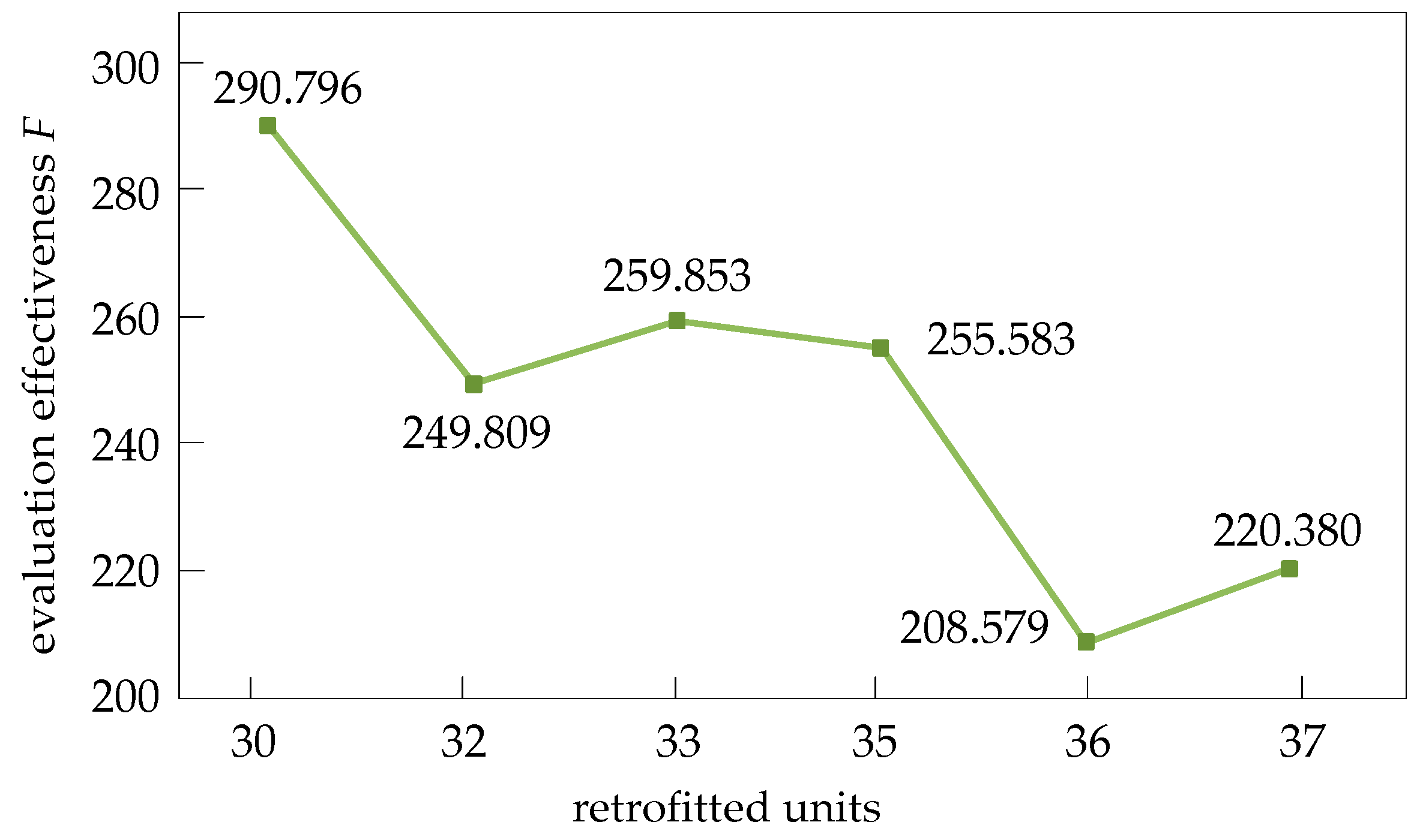
Comprehensive evaluation indexes for different unit modifications are calculated based on Equation (19) and Appendix C, as shown in Figure 9. As can be seen in Figure 9, the modification of the thermal unit’s synchronous condenser operation at node 30 can achieve a better overall enhancement effect due to the obvious effect of modifying unit 30 on enhancing the short-circuit ratio of the four wind farm aggregation points pooled at node 40. It is also worth noting that the aggregation station has a large main transformer capacity and a large area of influence; in addition, the retrofitted unit, which is a decommissioned unit, has a small capacity and therefore the highest overall rating. For the thermal power unit at node 36, the comprehensive improvement effect of synchronous condenser operation is the worst because the improvement effect on the short-circuit ratio is small and the unit has a large capacity, as it is an active unit. Therefore, the thermal power unit at node 30 is selected for retrofitting.

5. Conclusions

Faced with the challenges of weakening grid strength and insufficient voltage support capacity in the context of high renewable energy integration, this study systematically investigates the enhancement effect of synchronous condenser operation in thermal power generating units on the grid strength of renewable energy aggregation sites through theoretical analysis and case study validation, and proposes a multi-dimensional evaluation method. A mathematical model of thermal power units in generation, shutdown, and synchronous condenser operation states is constructed based on the physical nature of short-circuit ratio, revealing the core mechanism through which the synchronous condenser operation of thermal power units enhances the short-circuit ratio.
In addition, this paper proposes a multi-dimensional evaluation system that includes the following: the change in short-circuit ratio at grid-connection points of multiple renewable energy stations ( Δ M R S C R S ), the main transformer capacity within short-circuit ratio enhancement range ( S T ), the pre-retrofit short-circuit ratio level at grid-connection points of multiple renewable energy stations ( S G ), and the retrofitted unit capacity ( M R S C R S ). By combining hierarchical analysis and the entropy weighting strategy, we resolved the traditional single-index evaluation issues of one-sidedness and subjectivity. An example validate that the method can scientifically assess the comprehensive value of retrofitting thermal power units for synchronous condenser operation and provides a theoretical foundation for retrofitting retired thermal power units into synchronous condenser.
Finally, case validation using the IEEE 39-bus system confirms the effectiveness of the proposed evaluation method. The results show that synchronous condenser operation of thermal units significantly increases the short-circuit ratio of multiple renewable energy sites, thereby enhancing overall grid strength. According to the multi-dimensional evaluation, the thermal unit at node 30 is identified as the optimal candidate for retrofitting—it has the smallest capacity and is located closest to the renewable energy stations. This method offers a scientifically sound approach for assessing the overall value of retrofitting retired thermal units as synchronous condensers and provides planning support for such upgrades. Future research will further examine the feasibility of this retrofit from two perspectives: economic viability and transient performance. On one hand, the cost of retrofitting thermal units of various capacities will be evaluated to identify the most cost-effective and technically feasible solutions. On the other hand, the transient and sub-transient characteristics of retrofitted units will be analyzed, focusing on their ability to provide reactive power support during short-term grid disturbances—critical for maintaining stability under high renewable energy penetration.

Author Contributions

Conceptualization, J.Y.; Methodology, S.C.; Software, W.T.; Data curation, Z.C.; Writing—original draft, J.H.; Writing—review & editing, X.Z.; Project administration, K.W. All authors have read and agreed to the published version of the manuscript.

Funding

This research was funded by the State Grid Northeast China Branch.

Data Availability Statement

Data are contained within the article.

Conflicts of Interest

Authors Keming Wu, Zelong Chen, Jinshi You, Shuai Cao and Wei Tang were employed by the company Northeast Branch of State Grid Corporation of China. The remaining authors declare that the research was conducted in the absence of any commercial or financial relationships that could be construed as a potential conflict of interest.

Appendix A

The short-circuit ratio at the machine end of the new energy field station (nodes 43, 47, 51) and the short-circuit ratio at the grid-connected points (nodes 41, 45, 49) when the thermal power units are shut down at node 32 were calculated, and the specific data are shown in Table A1 and Table A2.
Table A1. Short-Circuit Ratio at the Machine End of the New Energy Field Station when the Thermal Unit at Node 32 is Shut Down.
P 43 P 47 P 51 M R S C R G , 43 M R S C R G , 47 M R S C R G , 51
2.452.652.851.70051.66751.6240
2.502.702.901.66821.63471.5926
2.552.752.951.63701.60321.5624
2.602.803.001.60681.57271.5332
Table A2. Short-Circuit Ratio at the Grid-connected Points of the New Energy Field Station when the Thermal Unit at Node 32 is Shut Down.
P 43 P 47 P 51 M R S C R S , 41 M R S C R S , 45 M R S C R S , 49
2.452.652.852.25192.16392.0924
2.502.702.902.20832.12102.0517
2.552.752.952.16642.07962.0124
2.602.803.002.12582.03961.9745
The short-circuit ratio at the machine end of the new energy field station (nodes 43, 47, 51) and the short-circuit ratio at the grid-connected point (nodes 41, 45, 49) when the thermal power unit at node 32 is in synchronous condenser operation were calculated, and the specific data are shown in Table A3 and Table A4.
Table A3. Short-Circuit Ratio at the Machine End of the New Energy Field Station during Synchronous Condenser Operation of Thermal Power Units at Node 32.
P 43 P 47 P 51 M R S C R G , 43 M R S C R G , 47 M R S C R G , 51
2.452.652.851.71281.68231.6335
2.502.702.901.68021.64931.6019
2.552.752.951.64881.61751.5715
2.602.803.001.61851.58681.5422
Table A4. Short-Circuit Ratio at the Grid-connected Points of New Energy Field Stations during Synchronous Condenser Operation of Thermal Power Units at Node 32.
P 43 P 47 P 51 M R S C R S , 41 M R S C R S , 45 M R S C R S , 49
2.452.652.852.29132.20082.1199
2.502.702.902.24702.15732.0786
2.552.752.952.20432.11522.0389
2.602.803.002.16312.07472.0005
The short-circuit ratio at the machine end of the new energy field station (nodes 43, 47, 51) and the short-circuit ratio at the grid-connected points (nodes 41, 45, 49) when the thermal power units are shut down at node 33 were calculated, and the specific data are shown in Table A5 and Table A6.
Table A5. Short-Circuit Ratio at the Machine End of the New Energy Field Station when the Thermal Unit at Node 33 is Shut Down.
P 43 P 47 P 51 M R S C R G , 43 M R S C R G , 47 M R S C R G , 51
2.452.652.851.70671.65531.6188
2.502.702.901.67441.62301.5876
2.552.752.951.64321.59191.5576
2.602.803.001.61311.56181.5286
Table A6. Short-Circuit Ratio at the Grid-connected Points of the New Energy Field Station when the Thermal Unit at Node 33 is Shut Down.
P 43 P 47 P 51 M R S C R S , 41 M R S C R S , 45 M R S C R S , 49
2.452.652.852.27402.10352.0715
2.502.702.902.23042.06222.0315
2.552.752.952.18842.02231.9928
2.602.803.002.14781.98391.9556
The short-circuit ratio at the machine end of the new energy field station (nodes 43, 47, 51) and the short-circuit ratio at the grid-connected point (nodes 41, 45, 49) when the thermal power unit at node 33 is in synchronous condenser operation were calculated, and the specific data are shown in Table A7 and Table A8.
Table A7. Short-Circuit Ratio at the Machine End of the New Energy Field Station during Synchronous Condenser Operation of Thermal Power Units at Node 33.
P 43 P 47 P 51 M R S C R G , 43 M R S C R G , 47 M R S C R G , 51
2.452.652.851.71351.69831.6492
2.502.702.901.68111.66531.6277
2.552.752.951.64981.63341.5872
2.602.803.001.61961.60271.5579
Table A8. Short-Circuit Ratio at the Grid-connected Points of New Energy Field Stations during Synchronous Condenser Operation of Thermal Power Units at Node 33.
P 43 P 47 P 51 M R S C R S , 41 M R S C R S , 45 M R S C R S , 49
2.452.652.852.29312.23062.1533
2.502.702.902.24912.18692.1121
2.552.752.952.20682.14472.0724
2.602.803.002.16592.10412.0341
The short-circuit ratio at the machine end of the new energy field station (nodes 43, 47, 51) and the short-circuit ratio at the grid-connected points (nodes 41, 45, 49) when the thermal power units are shut down at node 35 were calculated, and the specific data are shown in Table A9 and Table A10.
Table A9. Short-Circuit Ratio at the Machine End of the New Energy Field Station when the Thermal Unit at Node 35 is Shut Down.
P 43 P 47 P 51 M R S C R G , 43 M R S C R G , 47 M R S C R G , 51
2.452.652.851.69661.65411.6112
2.502.702.901.66431.62191.5870
2.552.752.951.63321.59081.5570
2.602.803.001.60311.56081.5281
Table A10. Short-Circuit Ratio at the Grid-connected Points of the New Energy Field Station when the Thermal Unit at Node 35 is Shut Down.
P 43 P 47 P 51 M R S C R S , 41 M R S C R S , 45 M R S C R S , 49
2.452.652.852.27392.10162.0702
2.502.702.902.23042.06032.0303
2.552.752.952.18842.02061.9917
2.602.803.002.14781.98221.9545
The short-circuit ratio at the machine end of the new energy field station (nodes 43, 47, 51) and the short-circuit ratio at the grid-connected point (nodes 41, 45, 49) when the thermal power unit at node 35 is in synchronous condenser operation were calculated, and the specific data are shown in Table A11 and Table A12.
Table A11. Short-Circuit Ratio at the Machine End of the New Energy Field Station during Synchronous Condenser Operation of Thermal Power Units at Node 35.
P 43 P 47 P 51 M R S C R G , 43 M R S C R G , 47 M R S C R G , 51
2.452.652.851.71421.70161.6321
2.502.702.901.68181.66851.6088
2.552.752.951.65051.63661.5784
2.602.803.001.62031.60581.5491
Table A12. Short-Circuit Ratio at the Grid-connected Points of New Energy Field Stations during Synchronous Condenser Operation of Thermal Power Units at Node 35.
P 43 P 47 P 51 M R S C R S , 41 M R S C R S , 45 M R S C R S , 49
2.452.652.852.29462.22642.1362
2.502.702.902.25072.18272.0950
2.552.752.952.20832.14052.0553
2.602.803.002.16752.09982.0169
The short-circuit ratio at the machine end of the new energy field station (nodes 43, 47, 51) and the short-circuit ratio at the grid-connected points (nodes 41, 45, 49) when the thermal power units are shut down at node 36 were calculated, and the specific data are shown in Table A13 and Table A14.
Table A13. Short-Circuit Ratio at the Machine End of the New Energy Field Station when the Thermal Unit at Node 36 is Shut Down.
P 43 P 47 P 51 M R S C R G , 43 M R S C R G , 47 M R S C R G , 51
2.452.652.851.70941.67181.6264
2.502.702.901.67711.63941.5951
2.552.752.951.64591.60811.5650
2.602.803.001.61591.57791.5360
Table A14. Short-Circuit Ratio at the Grid-connected Points of the New Energy Field Station when the Thermal Unit at Node 36 is Shut Down.
P 43 P 47 P 51 M R S C R S , 41 M R S C R S , 45 M R S C R S , 49
2.452.652.852.28192.15652.0964
2.502.702.902.23832.11442.0560
2.552.752.952.19632.07382.0171
2.602.803.002.15562.03461.9795
The short-circuit ratio at the machine end of the new energy field station (nodes 43, 47, 51) and the short-circuit ratio at the grid-connected point (nodes 41, 45, 49) when the thermal power unit at node 36 is in synchronous condenser operation were calculated, and the specific data are shown in Table A15 and Table A16.
Table A15. Short-Circuit Ratio at the Machine End of the New Energy Field Station during Synchronous Condenser Operation of Thermal Power Units at Node 36.
P 43 P 47 P 51 M R S C R G , 43 M R S C R G , 47 M R S C R G , 51
2.452.652.851.71511.70581.6423
2.502.702.901.68261.67271.6107
2.552.752.951.65141.64081.5803
2.602.803.001.62121.61011.5510
Table A16. Short-Circuit Ratio at the Grid-connected Points of New Energy Field Stations during Synchronous Condenser Operation of Thermal Power Units at Node 36.
P 43 P 47 P 51 M R S C R S , 41 M R S C R S , 45 M R S C R S , 49
2.452.652.852.29682.24482.1407
2.502.702.902.25292.20102.0995
2.552.752.952.21062.15882.0598
2.602.803.002.16972.11812.0215
The short-circuit ratio at the machine end of the new energy field station (nodes 43, 47, 51) and the short-circuit ratio at the grid-connected points (nodes 41, 45, 49) when the thermal power units are shut down at node 37 were calculated, and the specific data are shown in Table A17 and Table A18.
Table A17. Short-Circuit Ratio at the Machine End of the New Energy Field Station when the Thermal Unit at Node 37 is Shut Down.
P 43 P 47 P 51 M R S C R G , 43 M R S C R G , 47 M R S C R G , 51
2.452.652.851.70711.67861.6283
2.502.702.901.67481.64601.5970
2.552.752.951.64371.61461.5668
2.602.803.001.61361.58421.5377
Table A18. Short-Circuit Ratio at the Grid-connected Points of the New Energy Field Station when the Thermal Unit at Node 37 is Shut Down.
P 43 P 47 P 51 M R S C R S , 41 M R S C R S , 45 M R S C R S , 49
2.452.652.852.26162.19022.1006
2.502.702.902.21832.14742.0601
2.552.752.952.17662.10612.0210
2.602.803.002.13642.06621.9833
The short-circuit ratio at the machine end of the new energy field station (nodes 43, 47, 51) and the short-circuit ratio at the grid-connected point (nodes 41, 45, 49) when the thermal power unit at node 37 is in synchronous condenser operation were calculated, and the specific data are shown in Table A19 and Table A20.
Table A19. Short-Circuit Ratio at the Machine End of the New Energy Field Station during Synchronous Condenser Operation of Thermal Power Units at Node 37.
P 43 P 47 P 51 M R S C R G , 43 M R S C R G , 47 M R S C R G , 51
2.452.652.851.72751.68901.6430
2.502.702.901.69481.65621.6114
2.552.752.951.66341.62461.5810
2.602.803.001.63301.59411.5517
Table A20. Short-Circuit Ratio at the Grid-connected Points of New Energy Field Stations during Synchronous Condenser Operation of Thermal Power Units at Node 37.
P 43 P 47 P 51 M R S C R S , 41 M R S C R S , 45 M R S C R S , 49
2.452.652.852.32642.21362.1424
2.502.702.902.28202.17042.1012
2.552.752.952.23912.12872.0614
2.602.803.002.19782.08852.0230

Appendix B

Table A21. Statistical Table of Short-Circuit Ratio Improvement Effect Before and After Modification.
Point of Common Coupling for Wind FarmsRetrofitted NodeWind Power at the Point of Common Coupling Δ M R S C R S S T (MVA) M R S C R S S G (MW)
41302600.105112002.0726300
411302600.105112002.0726300
412302600.105112002.0726300
413302600.105112002.0726300
45302800.02059002.0542300
451302800.02059002.0542300
452302800.02059002.0542300
49303000.03866001.9680300
491303000.03866001.9680300
41322600.037312002.1258350
411322600.037312002.1258350
412322600.037312002.1258350
413322600.037312002.1258350
45322800.03519002.0396350
451322800.03519002.0396350
452322800.03519002.0396350
49323000.0266001.9745350
491323000.0266001.9745350
41332600.018112002.1478400
411332600.018112002.1478400
412332600.018112002.1478400
413332600.018112002.1478400
45332800.12029001.9839400
451332800.12029001.9839400
452332800.12029001.9839400
49333000.07856001.9556400
491333000.07856001.9556400
41352600.019712002.1478450
411352600.019712002.1478450
412352600.019712002.1478450
413352600.019712002.1478450
45352800.11769001.9822450
451352800.11769001.9822450
452352800.11769001.9822450
49353000.06246001.9545450
491353000.06246001.9545450
41362600.014112002.1556500
411362600.014112002.1556500
412362600.014112002.1556500
413362600.014112002.1556500
45362800.08359002.0346500
451362800.08359002.0346500
452362800.08359002.0346500
49363000.0426001.9795500
491363000.0426001.9795500
41372600.061412002.1364550
411372600.061412002.1364550
412372600.061412002.1364550
413372600.061412002.1364550
45372800.02239002.0662550
451372800.02239002.0662550
452372800.02239002.0662550
49373000.03976001.9833550
491373000.03976001.9833550

Appendix C

Table A22. Scoring Table of Short-Circuit Ratio Improvement Effect Before and After Modification.
Point of Common Coupling for Wind FarmsRetrofitted Node Δ M R S C R S S T (MVA) M R S C R S S G (MW)
413046.542.522.550
4113046.542.522.550
4123046.542.522.550
4133046.542.522.550
45301421.52950
451301421.52950
452301421.52950
493028.56.549.550
4913028.56.549.550
413225.542.518.541
4113225.542.518.541
4123225.542.518.541
4133225.542.518.541
45322221.53241
451322221.53241
452322221.53241
493219.56.547.541
4913219.56.547.541
41336.542.58.532
411336.542.58.532
412336.542.58.532
413336.542.58.532
45335321.53832
451335321.53832
452335321.53832
493340.56.551.532
4913340.56.551.532
413510.542.58.523
4113510.542.58.523
4123510.542.58.523
4133510.542.58.523
45355021.54323
451355021.54323
452355021.54323
493538.56.553.523
4913538.56.553.523
41362.542.52.514
411362.542.52.514
412362.542.52.514
413362.542.52.514
45364321.53514
451364321.53514
452364321.53514
493632.56.545.514
4913632.56.545.514
413735.542.514.55
4113735.542.514.55
4123735.542.514.55
4133735.542.514.55
45371721.5265
451371721.5265
452371721.5265
493730.56.540.55
4913730.56.540.55

References

  1. Zhang, Z.; Kang, C. Challenges and prospects for constructing the new-type power system towards a carbon neutrality future. Proc. CSEE 2022, 42, 2806–2818. [Google Scholar]
  2. Zhang, Z.; Zhang, N.; Du, E.; Kang, C.; Wang, Z. Review and countermeasures on frequency security issues of power systems with high shares of renewables and power electronics. Proc. CSEE 2022, 42, 1–25. [Google Scholar]
  3. Yang, Y.; Chen, H.; Hao, J.; Yang, Z.; Xu, G.; Duan, L. Development pathways for the transformation and upgrading of China’s coal-fired power generation under the goals of carbon peak and carbon neutrality. Proc. CSEE 2024, 44, 6900–6910. [Google Scholar]
  4. Zhuo, Z.; Zhang, N.; Xie, X.; Li, H.; Kang, C. Key technologies and developing challenges of power system with high proportion of renewable energy. Autom. Electr. Power Syst. 2021, 45, 171–191. [Google Scholar]
  5. Ma, H.; Li, X.; Wu, R.; Xu, X.; Li, B. Optimal Capacity Configuration Method for Multi-type Energy Storage Systems Enhancing New Energy Consumption and Actively Supporting the Grid. Electr. Power Constr. 2024, 45, 111–119. [Google Scholar]
  6. Garrido, C.; Aguila Téllez, A.; Ortiz, L. Linear Voltage Stability Indicator (LVSI) for Optimal Placement of SVC Devices to Improve the Voltage Stability Margin in Transmission Systems. Electronics 2023, 12, 43. [Google Scholar] [CrossRef]
  7. Falaghi, H.; Ramezani, M.; Elyasi, H.; Farhadi, M.; Estebsari, A. Risk-Based Capacitor Placement in Distribution Networks. Electronics 2022, 11, 3145. [Google Scholar] [CrossRef]
  8. Sun, Y.; Wu, H.; Song, X.; Zhang, H.; Zhang, Y.; Chen, J.; Liu, H. Analysis of Influence of Grid-Following and Grid-Forming Static Var Generators on High-Frequency Resonance in Doubly Fed Induction Generator-Based Wind Farms. Electronics 2024, 13, 3879. [Google Scholar] [CrossRef]
  9. Wang, Y.; Zhang, Y.; Zhou, Q.; Li, Z.; Jiang, Y.; Tang, Y. Study on application of new generation large capacity synchronous condenser in power grid. Power Syst. Technol. 2017, 41, 22–28. [Google Scholar]
  10. Suo, Z.; Li, H.; Zhang, F.; Jiang, W.; Wang, F.; Hu, A. Optimal configuration of a distributed synchronous condenser for an HVDC sending-end system with a high-proportion of renewable energy. Power Syst. Prot. Control 2022, 50, 133–141. [Google Scholar]
  11. Guo, Q.; Li, Z. Summarization of synchronous condenser development. Proc. CSEE 2023, 43, 6050–6063. [Google Scholar]
  12. Deng, B.; Wen, Y. Coordinated expansion planning of AC network and synchronous condenser for receiving-end grids with multi-infeed UHVDC links. CSEE J. Power Energy Syst. 2024, 1–13. [Google Scholar] [CrossRef]
  13. Fu, R.; Zhang, Y.; Wei, W.; Sun, X.; Li, B. A Configuration Method for Synchronous Condensers Driven by Full Electromagnetic Transient Simulation. Electronics 2025, 14, 1243. [Google Scholar] [CrossRef]
  14. Wang, Z.; Liu, M.; Li, H.; Qin, J.; Guo, J.; Bai, K. Optimal configuration method of synchronous condenser to improve delivery capacity of new energy cluster in weak grid. Electr. Power Autom. Equip. 2024, 44, 30–36. [Google Scholar]
  15. Sun, Z.; Qiao, J.; Meng, X.; Pan, C.; Li, Z.; Belikov, J.; Levron, Y. Hierarchical Optimization Configuration Strategy of Synchronous Condenser in High Penetration Wind Power Sending Systems. Electronics 2024, 13, 4359. [Google Scholar] [CrossRef]
  16. Masood, N.A.; Mahmud, S.U.; Ansary, M.N.; Deeba, S.R. Improvement of system strength under high wind penetration: A techno-economic assessment using synchronous condenser and SVC. Energy 2022, 246, 123426. [Google Scholar] [CrossRef]
  17. National Development and Reform Commission; National Energy Administration. Opinions on Improving the Mechanisms and Policy Measures for Green and Low-Carbon Energy Transition; National Development and Reform Commission: Beijing, China, 2022. [Google Scholar]
  18. Central China Energy Regulatory Office; National Energy Administration. Detailed Rules for the Management of Auxiliary Services in Power Plants and Grid-Connected Operation (Revised); National Energy Administration: Beijing, China, 2023. [Google Scholar]
  19. Zhou, Y.; Sun, H.; Xu, S.; Wang, X.; Zhao, B.; Zhu, Y. Synchronous condenser optimized configuration scheme for power grid voltage strength improvement. Power Syst. Technol. 2021, 46, 3848–3856. [Google Scholar]
  20. Kong, N. Research on Station Selection and Excitation Control of Retired Thermal Power Units Operate as Synchronous Condenser. Ph.D. Thesis, Lanzhou University of Science and Technology, Lanzhou, China, 2022. [Google Scholar]
  21. Fu, H.; Sun, R.; Wang, J.; Wang, X.; Li, H. Key technologies of adding a condenser function in thermal power units in the receiving end power grid given a background of carbon peak and neutrality. Power Syst. Prot. Control 2024, 52, 132–143. [Google Scholar]
  22. Ma, F. Assessment and Enhancement of Voltage Support Strength in Renewable-Energy-Integrated Power Systems with Grid-Forming Power Electronic Devices. Ph.D. Thesis, Zhejiang University, Hangzhou, China, 2024. [Google Scholar]
  23. Wang, S.; Gao, S.; Chen, Z.; Zhao, X.; Song, T.; Liu, Y.; Yu, D.; Jiang, S. Analysis of the Operating Margin Evaluation of Multi-Infeed LCC-HVDC Systems Based on the Equivalent Impedance. IEEE Access 2021, 9, 66268–66281. [Google Scholar] [CrossRef]
  24. Lin, W.; Tang, Y.; Bu, G. Definition and application of short circuit ratio for multi-infeed AC/DC power systems. Proc. CSEE 2008, 28, 1–8. [Google Scholar]
  25. Xin, H.; Zhang, F.; Yu, Y.; Gan, D.; Xu, Q. Generalized short circuit ratio for multi-infeed DC systems: Definition and theoretical analysis. Proc. CSEE 2016, 36, 633–647. [Google Scholar]
  26. Wang, S.; Wen, J.; Niu, Y.; Ma, L. A study on the influence of AC/DC system on MISCR. Power Grid Clean Energy 2021, 37, 1–8. [Google Scholar]
  27. Sun, H.; Xu, S.; Xu, T.; Guo, Q.; He, J.; Zhao, B. Definition and index of short circuit ratio for multiple renewable energy stations. Proc. CSEE 2021, 41, 497–505. [Google Scholar]
  28. Ma, L.; Chen, Y.; Tian, D.; Lou, J.; Li, Y.; Zhang, Y. Severity evaluation of multistage voltage sag based on an improved analytic hierarchy process. Power Syst. Prot. Control 2023, 51, 49–57. [Google Scholar]
  29. Wang, C.; Li, B.; Jiang, T.; Chen, H.; Li, X.; Liu, F. A contingency screening and ranking method based on improved fuzzy analytic hierarchy process for AC/DC receiving-end power grid AC faults. Power Syst. Technol. 2021, 45, 4047–4056. [Google Scholar]
  30. Meng, T.; Zhang, X.; Xiao, Y.; Li, F.; Jia, K.; Bi, T. Flexibility assessment of grid-connected converter for new energy generation based on entropy weight method. Proc. CSEE, 2024; in press. [Google Scholar]
  31. Qi, C.; Li, M.; Wu, Y.; Wang, Y.; Song, H. A fuzzy hierarchical selection method for an energy storage multi scenario interval based on maximum evaluation difference. Power Syst. Prot. Control 2024, 52, 104–115. [Google Scholar]
  32. Yu, L.; Jia, P.; Yang, Y.; Yan, X.; Zhang, L.; Wen, Y. Coordinated planning method for new energy station siting and network considering short circuit ratio constraints. Electr. Power Constr. 2024, 45, 24–33. [Google Scholar]
  33. Wu, L.; Xu, M.; Lin, J.; Xu, H.; Zheng, L. Active Power Dispatch of Renewable Energy Power Systems Considering Multiple Renewable Energy Station Short-Circuit Ratio Constraints. Electronics 2024, 13, 3811. [Google Scholar] [CrossRef]
  34. Yu, L.; Yan, G.; Yan, X.; Mao, Y.; Chen, S.; Li, T. Optimal planning of terminal locations and capacity of UHVDC considering constraints of receiving-end power grid support capability. Electr. Power 2024, 56, 175–185. [Google Scholar]
  35. Yu, L.; Sun, H.; Zhao, B.; Xu, S.; Zhang, J.; Li, Z. Short circuit ratio index analysis and critical short circuit ratio calculation of renewable energy grid-connected system. Proc. CSEE 2022, 42, 919–929. [Google Scholar]
  36. Wu, D.; Li, G.; Javadi, M.; Malyscheff, A.M.; Hong, M.; Jiang, J.N. Assessing impact of renewable energy integration on system strength using site-dependent short circuit ratio. IEEE Trans. Sustain. Energy 2018, 9, 1072–1080. [Google Scholar] [CrossRef]
  37. DL/T 2658-2023; Technical Specifications for Fast Dynamic Response Synchronous Regulator. National Energy Administration: Beijing, China, 2023.
  38. Li, S.; Ji, L.; Chang, X.; Hong, Q.; Ren, J.; Li, Z. Quantitative evaluation method of new energy voltage support capability based on improved whitening weight function clustering. Smart Power 2024, 52, 73–80. [Google Scholar]
  39. Wang, W.; Shi, L.; Qiu, Z. Multi-Indicator Fused Resilience Assessment of Power Grids Considering Wind-Photovoltaic Output Uncertainty During Typhoon Disasters. Electronics 2024, 13, 745. [Google Scholar] [CrossRef]
  40. Qin, J.; Li, H.; Sun, Y.; Wang, H. Optimal method of minimum start-up mode for conventional units considering new energy limit grid-connection strength constraint. Power Syst. Prot. Control 2023, 51, 127–135. [Google Scholar]
  41. Ebrie, A.S.; Kim, Y.J. Reinforcement learning-based optimization for power scheduling in a renewable energy connected grid. Renew. Energy 2024, 230, 120886. [Google Scholar] [CrossRef]
Figure 1. Schematic diagram of a short circuit at a new energy grid-connected point during thermal power unit generation operation.
Electronics 14 02467 g001
Figure 2. Schematic diagram of new energy grid-connected point short circuit when thermal power unit is shut down.
Electronics 14 02467 g002
Figure 3. Schematic diagram of new energy grid-connected point short circuit with synchronous condenser operation of thermal power unit.
Electronics 14 02467 g003
Figure 4. Modeling of multiple new energy stations and thermal power plants connected to the grid.
Electronics 14 02467 g004
Figure 5. Short-circuit ratio at the grid-connected point of wind farm 1 for thermal unit generation/synchronous condenser operation with different aggregation station main transformer capacities.
Electronics 14 02467 g005
Figure 6. Short-circuit ratio at the grid-connected point of wind farm 1 during generation/synchronous condenser operation of thermal power units of different capacities.
Electronics 14 02467 g006
Figure 7. Improved diagram of the IEEE-39 node system.
Electronics 14 02467 g007
Figure 8. The change in the short-circuit ratio of the new energy grid-connected point during the synchronous condenser operation of the thermal power unit.
Electronics 14 02467 g008
Figure 9. Diagram of multi-dimensional enhancement evaluation for selecting different units for retrofitting.
Electronics 14 02467 g009
Table 1. Short-circuit ratio at the machine end of the new energy field station when the thermal unit at node 30 is shut down.
P 43 P 47 P 51 M R S C R G , 43 M R S C R G , 47 M R S C R G , 51
2.452.652.851.68821.67301.6224
2.502.702.901.65611.64031.5911
2.552.752.951.62521.60881.5609
2.602.803.001.59531.57841.5318
Table 2. Short-circuit ratio at the grid-connected points of the new energy field station when the thermal unit at node 30 is shut down.
P 43 P 47 P 51 M R S C R S , 41 M R S C R S , 45 M R S C R S , 49
2.452.652.852.19532.17842.0851
2.502.702.902.15292.13552.0446
2.552.752.952.11202.09422.0056
2.602.803.002.07262.05421.9680
Table 3. Short-circuit ratio at the machine end of the new energy field station during synchronous condenser operation of thermal power units at node 30.
P 43 P 47 P 51 M R S C R G , 43 M R S C R G , 47 M R S C R G , 51
2.452.652.851.71911.68171.6361
2.502.702.901.68651.64891.6045
2.552.752.951.65501.63371.5741
2.602.803.001.62461.58671.5447
Table 4. Short-circuit ratio at the grid-connected points of new energy field stations during synchronous condenser operation of thermal power units at node 30.
P 43 P 47 P 51 M R S C R S , 41 M R S C R S , 45 M R S C R S , 49
2.452.652.852.30632.19992.1258
2.502.702.902.26192.15672.0846
2.552.752.952.21912.11502.0449
2.602.803.002.17772.07472.0066
Table 5. Set value of main transformer capacity of given aggregation station.
Nodal ( S T , MVA)
401200
44900
48600
Table 6. Set value of unit modification capacity.
Nodal ( S T , MW)Nodal ( S T , MW)
3030035450
3235036500
3340037550
Disclaimer/Publisher’s Note: The statements, opinions and data contained in all publications are solely those of the individual author(s) and contributor(s) and not of MDPI and/or the editor(s). MDPI and/or the editor(s) disclaim responsibility for any injury to people or property resulting from any ideas, methods, instructions or products referred to in the content.