1. Introduction
Modern electro-pneumatic systems are widely used in industrial automation due to their reliability, simple design and fast response. Pneumatic cylinders are essential components of many processing applications, such as clamping mechanisms, manipulators, and production lines, and their efficient control plays a key role in optimising production processes in terms of speed, accuracy, and energy efficiency [
1,
2,
3,
4,
5,
6].
In recent years, the digital twin has become an important tool for the design, testing and optimization of control strategies for electro-pneumatic actuators [
7,
8,
9]. It enables the simulation and validation of control algorithms prior to their physical deployment, thus minimizing the time and financial costs associated with the development of new systems.
To achieve realistic simulation, the accurate modelling of system dynamic properties such as lag, friction, air compressibility, pressure control, and flow are essential, as these parameters directly affect the dynamics of cylinder motion [
10,
11].
The digital twin consists of two basic parts—the geometric model and the behavioural model—and represents a key enabler of the Industry 4.0 paradigm, facilitating the integration of virtual and physical systems for advanced automation and smart manufacturing [
12,
13]. The geometric model provides the visualization and simulation of mechanical motions, while the behavioural model defines the control logic and physical properties of the system, such as motion dynamics, delays, friction, and interaction with input signals. Both parts are essential to accurately simulate the interaction between the mechanical and control elements of the system. Modelling of the digital twin can be achieved in the NX Mechatronics Concept Designer environment, which allows for the testing and optimization of control algorithms before their actual deployment [
14,
15,
16].
Reliable communication between the digital twin and the PLC control system is crucial for testing control strategies and validating control algorithms without the need for physical prototyping [
17]. For this purpose, M2M communication using the standardised OPC UA protocol is used [
18], which enables secure and bi-directional data exchange between the simulated and physical system, thus supporting virtual commissioning [
19,
20,
21,
22,
23,
24]. The accuracy of the transmission of signals, such as valve states, limit sensors, pressure, velocity, and piston position, are critical to the reliability of PLC program testing and the validation of the control strategies.
Different approaches have been used to model the digital twin, which differ in the level of detail of the physical description. Simple empirical models work with pre-set values that may not always correspond to the real behaviour of the system, leading to inaccuracies. Logic models allow for the testing of PLC algorithms, but do not describe the dynamics of the cylinder motion and its physical characteristics. Advanced physical models include gas dynamics and interaction with the control system, but their implementation is often computationally intensive and difficult to apply in practice.
This study focuses on the systematic analysis of different models of the behaviour of the digital twin of an electro-pneumatic actuator and the evaluation of their practical application in industrial automation. The aim is to identify models that offer an optimal balance between accuracy, ease of implementation, and efficiency of integration with control systems.
The main research goal is the identification of different models of the behaviour of the digital twin of the electro-pneumatic actuator and the evaluation of their advantages and disadvantages in terms of practical applicability. The most commonly used approaches to digital twin modelling and their advantages and limitations will be investigated, as well as the ease of implementation, maintenance, and modification of each model under industrial conditions; the trade-offs between model accuracy, computational complexity, and its practical applicability; as well as the possibilities of integrating a digital twin with a PLC control system via OPC UA M2M and the potential limitations of this communication.
To achieve these objectives, a model of the behaviour of the electro-pneumatic actuator will be designed and experimentally validated in the NX Mechatronics Concept Designer environment, and different approaches to modelling it will be explored. The model will include a 3D representation and a behavioural model, and its ability to accurately simulate the dynamic characteristics of the system will be evaluated. Validation will also focus on the accuracy of communication between the digital twin and the PLC system via the OPC UA M2M protocol.
This study brings benefits to both industrial practice and the research community. In industrial practice, it will provide recommendations for the selection of an appropriate digital twin model, optimize the cost and development time of control algorithms, and contribute to more reliable testing of PLC programs. For the research community, it will provide a systematic comparison of digital twin models, establish a basis for future research on hybrid models, and experimentally validate the possibilities of communication via OPC UA M2M.
The results of this study will allow for the classification of different models of the behaviour of digital twins of electro-pneumatic actuators; the identification of trade-offs between accuracy, flexibility, and ease of implementation; recommendations for the selection of the optimal model, depending on the application; and the analysis of the possibilities of interfacing the digital twin with PLC control via OPC UA M2M.
This study will contribute to a more accurate modelling of the behaviour of electro-pneumatic actuators and improve the design efficiency of digital twins in industrial applications, thus supporting their wider implementation in automated manufacturing processes.
The structure of this article is organized as follows to ensure a clear presentation of the modelling, implementation, and validation of the digital twin for an electro-pneumatic actuator.
The structure of the paper is organised into five main sections.
Section 1 presents the motivation for integrating digital twins into electro-pneumatic systems, underlining their significance for the virtual validation of control strategies and addressing current gaps in industrial automation research.
Section 3 describes the experimental setup, including the modelling of the Festo DSBC-32-100-PPSA-N3 pneumatic actuator (Festo Vertrieb GmbH & Co. KG, Esslingen, Germany) using the Siemens NX Mechatronics Concept Designer, and its integration with SIMIT and PLCSIM Advanced (Siemens AG, Munich, Germany) via the OPC UA communication protocol.
Section 4 presents the simulation outputs of three distinct digital twin models, with a focus on piston displacement, velocity profiles, and analogue signal responses under varying control conditions.
Section 5 provides an assessment of model fidelity, responsiveness, and simulation stability, and explores the trade-offs between simulation accuracy and implementation complexity, with references to related studies. Finally,
Section 6 summarises the main findings, confirming the advantages of using high-fidelity pneumatic models for virtual commissioning, and outlines future work involving physical validation against real-world measurements.
2. Theoretical Background
The research to date has focused primarily on the temporal accuracy and physical fidelity of the simulations, with less attention paid to model flexibility, ease of implementation, and practical applicability in industrial settings. There is not enough research regarding which models are the most suitable in terms of their applicability in different industrial scenarios and what trade-offs are required in their selection.
In recent years, the development of digital twins has become a key area of industrial digitalization, with particular attention being paid to actuators and drive systems. Digital twins enable the creation of realistic simulations of mechanical, electrical, and pneumatic systems, leading to better predictive maintenance, more efficient testing, and optimization of production processes [
25]. The development of these models is particularly important in the field of pneumatic actuators, where simulations allow for the testing of their dynamic behaviour without the need for physical prototypes [
20].
Antonelli et al. [
26] presented a digital twin of the hydraulic actuator used in active suspensions, demonstrating the benefits of hybrid models for simulation validation. Similarly, Aydemir et al. [
27] discussed the development of virtual actuators and highlighted their use in the validation of predictive maintenance algorithms. In addition, Ciganek and Zemla [
28] focused on the design of a digital twin of a PLC system and its integration into a control environment, thus providing an important basis for the validation of digital models in industrial applications.
Predictive diagnostics are also important, and Xiong et al. [
29] investigated the use of digital twins in the degradation of electro-pneumatic valves. Giordano focused on the validation of predictive algorithms for electromechanical actuators via digital twins [
30]. Smid (2023) developed a digital twin of an electromechanical actuator (EMA) and used it for the real-time monitoring of component degradation [
31].
In the area of simulation of pneumatic actuators, the research has focused on the accuracy of the models and their ability to represent the real behaviour of the systems. Damrath et al. experimentally validated a physical model of pneumatic components used in the automotive industry, highlighting the importance of detailed simulations for the verification of control algorithms [
32]. Strahilov and Damrath demonstrated the use of a digital twin to simulate the behaviour of pneumatic actuators for virtual commissioning [
10].
More recent studies have focused on the use of finite element methods and advanced machine algorithms to optimize simulations of pneumatic soft actuators [
33]. Trentini et al. proposed a comprehensive mathematical model of a servo-pneumatic system that includes friction, temperature, pressure, heat transfer, leakage between chambers and the environment, and the balance of forces in the cylinder [
34]. Faltus et al. presented the modelling of pneumatically driven systems using advanced finite element methods [
35].
An important technology in this area is the NX Mechatronics Concept Designer (NX MCD), which enables the modelling of pneumatic actuators and cylinders. A study by Zemla & Ciganek looked at a programmable virtual model of a mechatronic system in the NX 12 environment [
36]; Li & Yang developed a digital twin of the NX MCD-based sorting system, but without deeper validation of data accuracy and reliability for industrial practice [
37]. Miseo investigated the use of virtual commissioning of pneumatic servo systems in different phases (MIL, SIL, HIL) [
38]. Modelling of pneumatic systems also includes an approach to classifying and monitoring airflow in a digital environment, as demonstrated by Yu et al. in the development of a digital twin of a pneumatic classifier [
33].
Research in the field of digital twins for pneumatic actuators encompasses a wide range of approaches, from the physical modelling of components to the virtual commissioning and validation of control algorithms. While accurate simulation models exist for the physical behaviour of actuators, the challenge remains to ensure their reliability when communicating with real control systems and to validate the simulated signals under industrial conditions.
3. Materials and Method
The simulation and testing of digital twins play a key role in the design and optimization of industrial control systems. The use of virtual commissioning methods enables the validation and debugging of control algorithms without the need for the physical deployment of the device, thereby significantly shortening the development cycle and reducing the costs associated with testing under real-world conditions.
This section describes a methodological approach to the experimental validation of the digital twin of the electro-pneumatic actuator, focusing on its ability to replicate real-world control strategies, analyse changes in control settings, and provide a reliable testbed for testing different configurations of control algorithms.
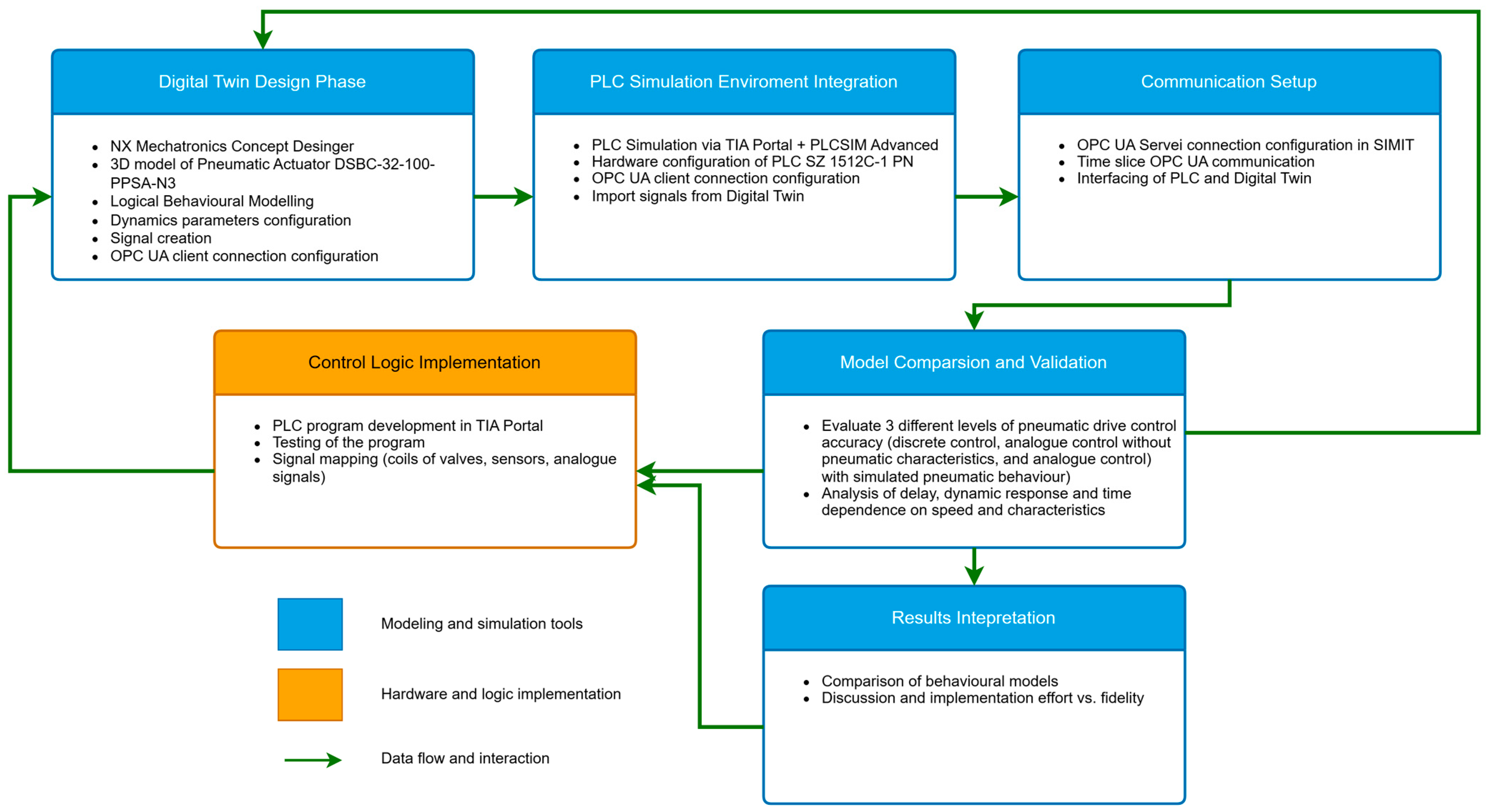
A comprehensive overview of the entire methodology, including the main modelling, simulation, and validation steps, is presented in
Figure 1. This process flowchart outlines the individual phases of digital twin design, PLC integration, OPC UA communication configuration, and validation experiments, providing a clear and replicable structure for future implementations in industrial contexts.
3.1. Experimental Environment and Software
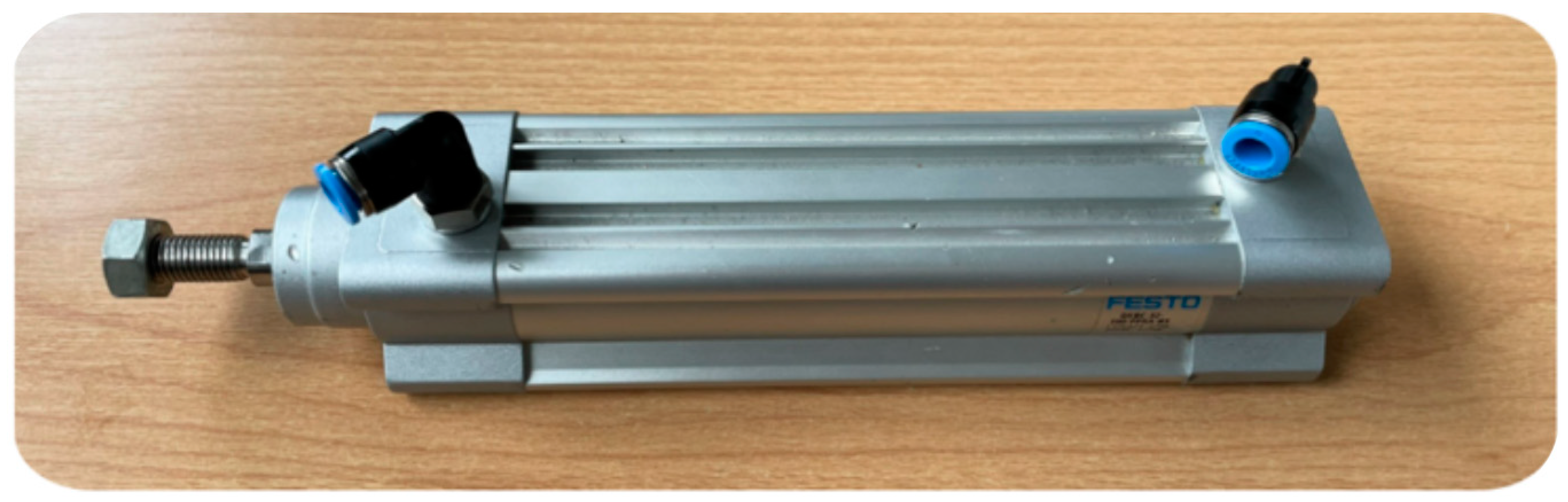
Experimental testing was conducted using the ISO standard [
39] Festo DSBC-32-100-PPSA-N3 pneumatic cylinder, located in the HUB4.0 laboratory (
Figure 1 and
Table 1), Festo Vertrieb GmbH & Co. KG, Esslingen, Germany.
This roller is widely used in industrial automation due to its reliability and precision motion, which allowed for a detailed analysis of its control in a simulated environment.
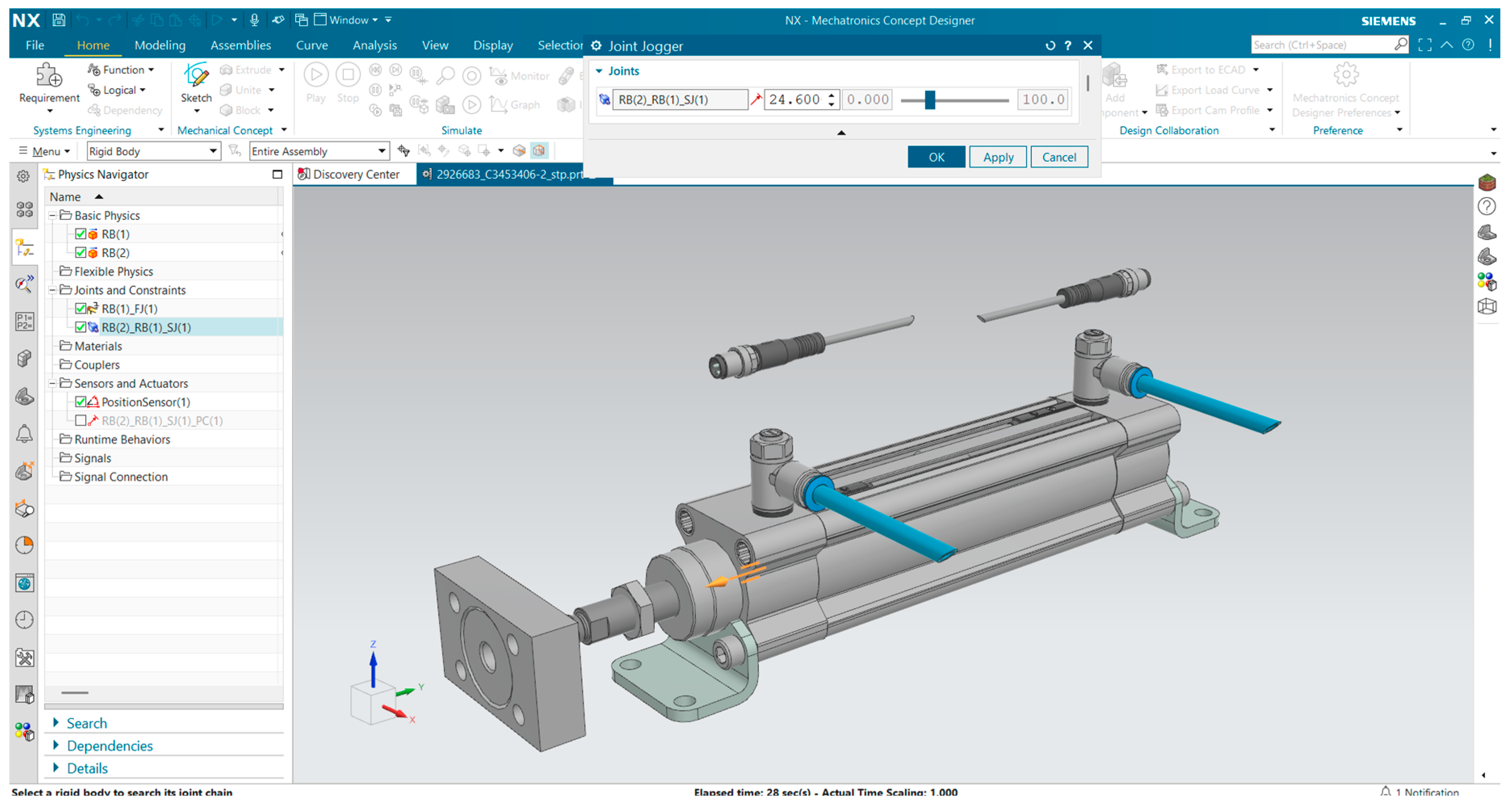
The digital twin of the pneumatic cylinder (
Figure 2 and
Figure 3) was created in The the Siemens NX Mechatronics Concept Designer 2412 (NX MCD 2412), Siemens AG, Munich, Germany, which provides advanced tools for modelling mechanical systems and simulating their dynamics.
The model included precisely defined mechanical dimensions, component weights, and material properties, thus providing a realistic simulation of the cylinder motion. The kinematics and dynamics of the motion, including friction, delay, air compressibility, end-position damping, and response to control signals, were considered in the simulation.
OPC UA-Based Co-Simulation Architecture
In this study, a co-simulation framework was established using the OPC UA communication protocol, enabling real-time interaction between the virtual control logic, physical system emulation, and the digital twin of a pneumatic actuator. The system architecture is composed of SIMIT as the OPC UA server, and two OPC UA clients—PLCSIM Advanced and NX Mechatronics Concept Designer (NX MCD)—operating in parallel.
The OPC UA server was configured in SIMIT, which emulates the dynamic behaviour of the pneumatic actuator, providing sensor feedback (e.g., position, velocity, and pressure) and actuator responses.
The server exposes these signals through a structured namespace accessible at the endpoint: opc.tcp://uvte-d-ruzarovs:47144. To ensure data integrity and communication security, the OPC UA server was configured to use the Basic256Sha256 security policy with the Sign&Encrypt message mode. User authentication was enforced through defined username and password credentials within the SIMIT security manager.
Additionally, communication security is enhanced using certificates and cryptographic keys. Server certificates are stored in directory C:\ProgramData\Siemens\Automation\SIMIT\8.0\PKI\own\certs, while trusted client certificates are stored in C:\ProgramData\Siemens\Automation\SIMIT\8.0\PKI\trusted\certs. This ensures the trustworthiness and integrity of the transmitted data, which is particularly important in scenarios requiring accuracy and safety, such as virtual commissioning.
On the client side, PLCSIM Advanced was configured via TIA Portal V17, using standard OPC UA communication blocks (OPC_UA_Connect, OPC_UA_Read, OPC_UA_Write). The namespace from SIMIT was imported into the PLC project, and each variable was mapped to corresponding PLC tags. The communication cycle was set to 2 ms, allowing for high-frequency signal updates and the real-time responsiveness of the control loop.
Simultaneously, NX MCD functioned as an OPC UA client by importing the SIMIT address space and mapping the relevant variables through its signal mapping interface. These variables were linked to simulation components, enabling the closed-loop synchronisation of virtual movements and actuator behaviour. NX MCD was also set to operate with a 2 ms communication interval, matching the update rate of the PLC client.
Within this configuration, SIMIT acted not only as a communication hub but also as a transducer layer, replacing missing physical components that were not part of the 3D model or the PLC logic. It allowed for the creation of both emulation type bindings for communication with PLCSIM Advanced (on the local address 127.0.0.1) and co-simulation type bindings for synchronisation with NX MCD through a dedicated simulation channel. Through this architecture, digital binary signals (such as valve activation or sensor triggers), as well as analogue quantities (pressure, airflow, position), were transmitted via OPC UA, enabling a comprehensive evaluation of the digital twin’s behaviour.
This architecture allows for high-resolution and synchronised co-simulation, enabling realistic testing of the digital twin under virtual conditions. The integration of secure OPC UA communication, fast update rates, and modular configuration ensures the robustness and reproducibility of the experimental results.
Although alternative configurations are possible—such as coupling the emulation of the control logic in PLCSIM Advanced directly with the simulation environment in NX MCD via internal signal mapping or SIMIT-native interfacing—our experimental setup was deliberately designed to rely on explicit OPC UA communication between the components.
This approach was selected not only to validate the interoperability and robustness of the digital twin under real-time conditions but also to facilitate future extension towards real hardware-in-the-loop (HiL) testing, including the integration of a physical pneumatic actuator.
By implementing OPC UA at this stage, the communication layer remains consistent regardless of whether the digital twin is interacting with emulated components or real devices, thus ensuring the scalability and continuity of the co-simulation framework.
A visual representation of this setup is provided in
Figure 4, which illustrates the signal flow diagram of the co-simulation architecture. SIMIT acts as the OPC UA server, providing simulated signals, while PLCSIM Advanced and NX MCD operate as OPC UA clients to execute control logic and simulate the behaviour of a pneumatic actuator.
This configuration enables the closed loop testing of a digital twin, where the actuator’s dynamics are virtually emulated and synchronised with the PLC program in real time.
3.2. Experimental Methodology
The experimental methodology focused on validating the digital twin’s ability to simulate the control of a pneumatic actuator and evaluating its applicability in virtual commissioning. The study followed a practical industrial automation perspective to investigate how accurately a virtual model can replicate the real-world control strategies typically used for pneumatic systems.
Three different control models were created to represent varying levels of physical fidelity. The first model was based on basic binary ON/OFF logic with minimal feedback, simulating only the actuator’s extreme positions. The second model employed analogue control, allowing for finer adjustment of actuator movement but without simulating pneumatic dynamics in detail. The third and most advanced model incorporated physical effects such as air pressure build-up, flow rate limitations, frictional forces, and damping, thus offering a high-fidelity representation of the real pneumatic behaviour. These models were tested separately to allow for a detailed comparison of the system responses under different control conditions and complexities.
To facilitate safe and efficient testing without relying solely on physical components, a software-in-the-loop (SiL) approach was initially employed. This method enabled the full integration of virtual elements while maintaining the real-time execution of the control algorithms. The digital twin of the pneumatic actuator was developed in NX Mechatronics Concept Designer 2412 (NX MCD 2412), where its kinematic and dynamic properties were defined, including accurate mass, friction, and responses to input signals.
The control logic was designed in the Siemens TIA Portal, Siemens AG, Munich, Germany and executed using PLCSIM Advanced, which emulates the firmware behaviour of the Siemens S7-1512C-1 PN PLC from the S7-1500 family, Siemens AG, Munich, Germany. This specific PLC model is also available in the laboratory environment as a physical device, allowing for a direct transition from SiL to hardware-in-the-loop (HiL) testing. The SIMIT V10.3 simulation platform provided emulated sensor and actuator signals and replaced the physical components not present in the 3D model using configurable transducers. This allowed for comprehensive virtual commissioning and verification of the control strategy in the early development phases.
Unlike hardware-in-the-loop (HiL) testing, which requires actual physical devices and hardware interfaces, the SiL methodology allowed for rapid iteration and debugging, eliminating hardware availability constraints and reducing risks during the early development stages. At the same time, the selected architecture remains compatible with the future transition to HiL testing, enabling gradual extension toward integration with physical actuators and control systems.
For each control scenario, the interaction between the digital twin and the PLC logic was analysed in terms of responsiveness, accuracy, and feedback completeness. The collected signal data were recorded for each model’s response to varying PLC conditions, allowing a comparative assessment of performance and usability. This approach supported the early detection of potential issues in the control design while offering a scalable environment for further optimisation and deployment in industrial settings.
3.3. Model Implementation and Experimental Steps
The digital twin of the pneumatic cylinder was created in the NX Mechatronics Concept Designer 2412 (NX MCD 2412) software environment, where its kinematic and dynamic properties were modelled. The physical parameters of the components, such as weight, friction, or interaction with control signals, were defined in the design, thus ensuring a realistic simulation of the cylinder behaviour under different control strategies. As part of the experimental validation, three different control models were tested, each representing a different level of detail and interaction capability with the control system.
3.3.1. Experiment 1: Discrete Control (On/Off)
This model uses binary valve control without feedback, where the cylinder movement is initiated by simple logic signals of the type “open” and “close”. This is a common control method in simple industrial applications where neither speed nor motion control are required (
Table 2).
3.3.2. Experiment 2: Analogue Control Without Pneumatic Characteristics
This model allows for the continuous control of cylinder motion based on feedback from an analogue sensor (e.g., potentiometer) while ignoring airflow dynamics. It is a purely mechanical simulation of piston motion without physical influences such as delays, pressures, or valve resistance.
Table 3 presents the signals used in the NX MCD digital twin during Experiment 2.
3.3.3. Experiment 3: Analogue Control with Simulated Pneumatic Behaviour
This advanced model includes a realistic simulation of the pneumatic system, including air pressure, flow, friction, motion delay, and damping at the extremes. It allows for a more accurate analysis of the interaction between the physical parameters of the pneumatic cylinder and the control algorithm, increasing its usefulness in tuning complex control strategies. The signals in the NX MCD digital twin from Experiment 3 are listed in
Table 4.
To ensure realistic testing, the models with analogue control were interfaced with the SIMIT emulation environment, which enabled the generation of control signals and their exchange with PLCSIM Advanced via a PLC program created in the TIA Portal. Thanks to this integration, it was possible to test different control strategies without the need for a physical device, allowing for a detailed analysis of the response of the digital twin to changes in the control algorithm.
This comprehensive approach has enabled a comparison of three different control methods in terms of their flexibility, configurability, and responsiveness to changes in control program settings, with the results serving as a basis for analysing the suitability of each approach in the context of designing and testing control algorithms.
3.4. Modelling of Piston Speed Based on Flow and Pressure Dynamics in a Double-Acting Pneumatic Cylinder
Double-acting pneumatic actuators conforming to ISO 15552 standards are widely applied due to their modularity and scalability. Their motion dynamics are governed by fundamental physical principles, yet they are significantly influenced by operational conditions such as throttling, backpressure, and air compressibility.
The net force acting on the piston results from the pressure difference between the chambers [
40]:
where
p1 and
p2 are absolute pressures,
A is the piston area, m is the total moving mass, and
is the acceleration.
Piston velocity is directly related to volumetric airflow and area:
where
is the speed,
A is the piston area, and
Q is the nominal flow.
Flow through the valve, under compressible conditions, follows a Bernoulli-type relationship:
where
Cd as the discharge coefficient;
Av(
xs) the valve opening area, dependent on spool position; and Δ
p = ps −
p indicates the pressure drops.
Chamber pressure evolution is modelled using the adiabatic ideal gas law:
where
κ = 1.4,
R = 287 J/(kg⋅K), and
V(
t) is the time-varying chamber volume.
These relationships show that piston speed is not constant—it depends on the pressure dynamics, valve behaviour, friction, and compressibility effects. In practice, the pressure ranges from 0.3 to 0.7 MPa, the flow rates span 100–2000 Nl/min, and the piston speeds typically lie between 0.1–1.5 m/s, scalable with cylinder size [
41].
Flow control valves or restrictors installed at the ports of a pneumatic cylinder introduce controlled resistance to airflow. This affects both the filling of the supply chamber and the evacuation of the exhaust chamber. The mass flow rate ṁ through a restriction under subsonic compressible flow conditions is expressed as
where
ṁ is the mass flow rate,
Cd is the discharge coefficient,
Ath is the effective throttling area,
is the upstream air density, and
pup and
pdown are the upstream and downstream absolute pressures.
For practical purposes and under isothermal flow assumptions, the normalized volumetric flow rate
Qn may be used, as follows:
where
Qn is the normalized flow rate,
C is an empirical flow coefficient, and Δ
p = pup − pdown is the pressure drop across the throttle.
When throttling is applied on the exhaust side, it increases the backpressure
(p2 > patm), which reduces the net driving force acting on the piston:
where
Fnet is the effective force,
pin is the supply pressure in the active chamber,
pexh is the backpressure, and
A is the piston area. This results in slower retraction, a non-linear piston speed, and possible asymmetry between strokes. In simulations, throttling is modelled using nonlinear resistance terms or integrated into the boundary conditions of the mass flow equations. This flow–pressure coupling must be accurately captured to represent transient and steady-state dynamics, especially in systems with long strokes or limited exhaust capacity [
42].
These dynamic dependencies were implemented in a case study using the Festo DSBC-32-100-PPSA-N3 actuator (32 mm bore, 100 mm stroke), Festo Vertrieb GmbH & Co. KG, Esslingen, Germany, in the Siemens NX Mechatronics Concept Designer environment, Siemens AG, Munich, Germany. The digital model integrates mechanical and pneumatic domains, time-varying chamber pressures, and throttling-induced flow restrictions. Simulation outputs demonstrate how pressure asymmetry, valve timing, and restrictor settings affect piston dynamics. The model is scalable and adaptable to other actuator sizes, forming a robust foundation for virtual commissioning and digital twin applications.
3.5. Evaluation Objectives and Criteria
Within the experimental methodology, four main areas were defined to be evaluated during the simulations to verify the ability of the digital twin to represent the real behaviour of a PLC-controlled pneumatic system.
Possibility of influencing the control—the aim was to find out to what extent it is possible to influence the cylinder motion via PLC inputs. The response of the individual models to changes in control parameters, such as desired speed or target position, was investigated, along with how these changes affect the simulation itself.
Response to change of settings—the ability of the digital twin to reflect adjustments in the control algorithm was evaluated, particularly in analogue control (e.g., change in pressure, flow, or control curves) and timing in discrete control. Whether or not these changes would be reflected in the simulated real-time behaviour of the cylinder was investigated.
Dynamic behaviour under different configurations—three different control approaches (discrete, analogue without physics, and analogue with pneumatic features) were compared in terms of motion flow, velocity profile, and system dynamics. The aim was to identify differences in behaviour between the simple and the more physically faithful model.
Flexibility of the model when testing PLC programs—whether or not the digital twin allows for the testing of different control scenarios without the need for major configuration modifications, was investigated. How well the simulated model can react to changes in inputs and outputs, as well as whether it can be used for repeated testing of different PLC algorithms, was evaluated.
The evaluation took the form of a gradual change of control parameters in the PLC and the monitoring of the response of the simulated model. Consideration was given to whether the changes in the control program produce the expected system response, the speed of this response, and whether the model provides consistent results without the need to modify the digital twin.
3.6. Measurement and Evaluation Procedure
To objectively compare the different models of the digital twin, the measurable parameters were defined to quantify the behaviour of the pneumatic cylinder under different types of steering. These parameters were obtained directly from the simulation using sensors integrated into the models and were recorded in time sequence.
Main measured quantities:
Set speed—defined as an input value from the PLC side, representing the target piston movement speed (in mm/s).
Sensor velocity—obtained from a simulated velocity sensor, showing the actual cylinder motion over time.
Displacement—determined as the actual piston position, measured from zero position to the target value (typically 100 mm).
Electrical voltage from potentiometer—analogue output reflecting the piston position in the range of 0–10 V, used as feedback for control.
Motion rise time—measured as the time between the activation of the control input and the start of detectable motion.
Cycle time—the total time required to complete one complete cycle from the start position to the finish position.
The measurement and data recording procedure were as follows:
Simulation initialization—each experiment started from a standardized zero initial position.
Setting the desired speed—the value has been entered as a control input from the PLC (e.g., 10 mm/s, 25 mm/s, etc.).
Data acquisition—using the OPC UA interface, data from the PLC and the simulated model were temporarily synchronized.
Time-series recording—data was stored at 0.03 s intervals to produce a time series of data suitable for visualization.
Comparison of input and output—the desired speed was compared with the actual value achieved over time (see SPEED_x and TAB_x plots).
Evaluation of system response—observation were made regarding whether and how accurately the model responds to inputs, how quickly it reaches the desired values, and whether there are any deviations, fluctuations or delays present.
Tools used:
NX Mechatronics Concept Designer 2412—for motion simulation and dynamics calculation.
SIMIT V10.3—for sensor emulation, control inputs, and signal generation.
PLCSIM Advanced—for simulating PLC control and generating real inputs.
TIA Portal V17—for designing the control program that was emulated during the experiments.
This systematic approach allowed us to quantitatively compare the response of the different models and verify their suitability for testing PLC programs of different levels of complexity.
4. Results
During the simulations, parameters related to the flexibility of the digital model and its ability to adapt to changes in management strategies were recorded. The aim was to assess to what extent the different models allow for parameter adjustments and what effect these changes have on the behaviour of the pneumatic cylinder.
The analysis focused on the response of the models to modifications of the control algorithms and the ability to test PLC programs and reflect changes in system settings.
4.1. Results of Experiment 1: Discreet Control (On/Off)
This model uses binary valve control without feedback, where the cylinder motion is initiated by simple logic signals of the type “open” and “close”. This is a common control method in simple industrial applications where neither speed nor motion control is required.
4.2. Results of Experiment 2: Analogue Control Without Pneumatic Characteristics
This model allows for continuous control of the cylinder motion based on feedback from an analogue sensor (e.g., potentiometer), while ignoring airflow dynamics. It is a purely mechanical simulation of piston motion without physical influences such as delays, pressures, or valve resistance.
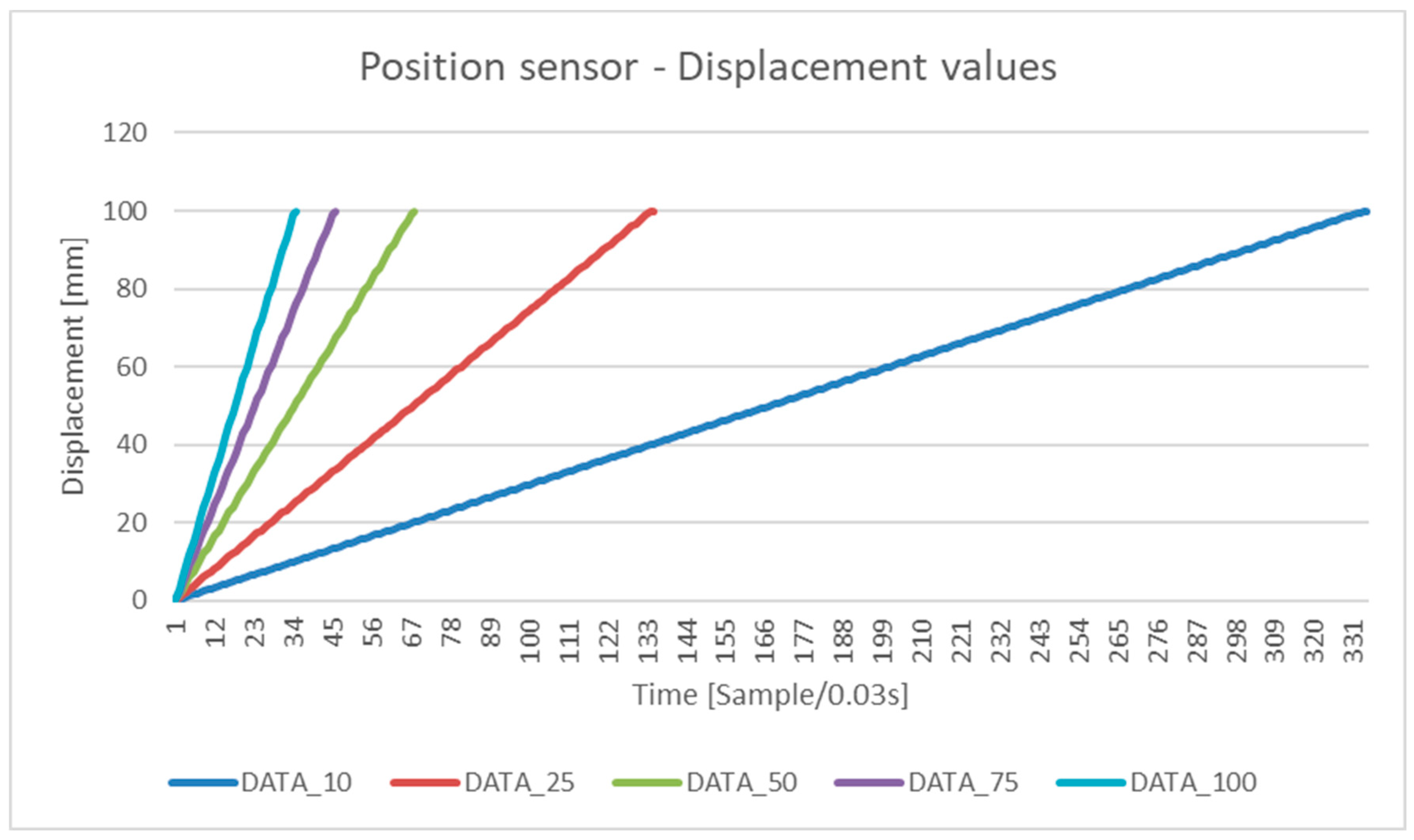
In both cases, different required piston movement speeds (10, 25, 50, 75, and 100 mm/s) were entered into the simulation. For each of these inputs, the following parameters were monitored:
instantaneous piston velocity over time;
the current piston position;
output voltage signal from the potentiometer (0–10 V).
The results of these simulations, shown in the
Figure 5,
Figure 6 and
Figure 7 below, are identical for Experiment 1 and Experiment 2.
For each variant, the velocity was constant throughout the movement and corresponded to the set value. The results show a uniform velocity setting with no fluctuations or dynamic changes.
Higher velocities (e.g., 100 mm/s) reached the target position earlier. The progression was linear, with no jumps or delays, and the duration of the movement was directly proportional to the specified velocity.
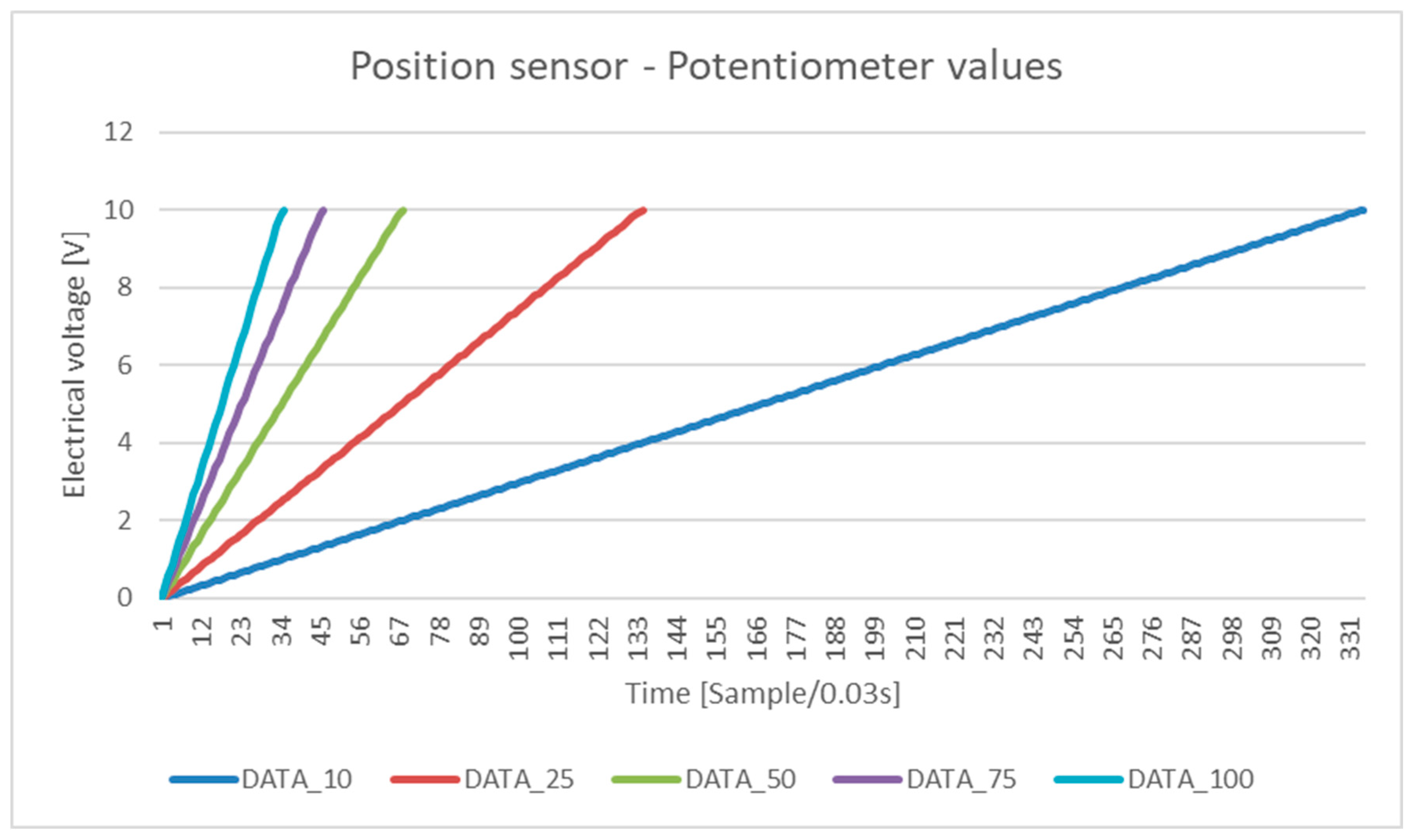
The output voltage increased proportionally with the movement of the piston. At higher speeds, the increase was faster, but the shape of the curve remained linear and stable.
4.3. Results of Experiment 3: Analogue Control with Simulated Pneumatic Behaviour
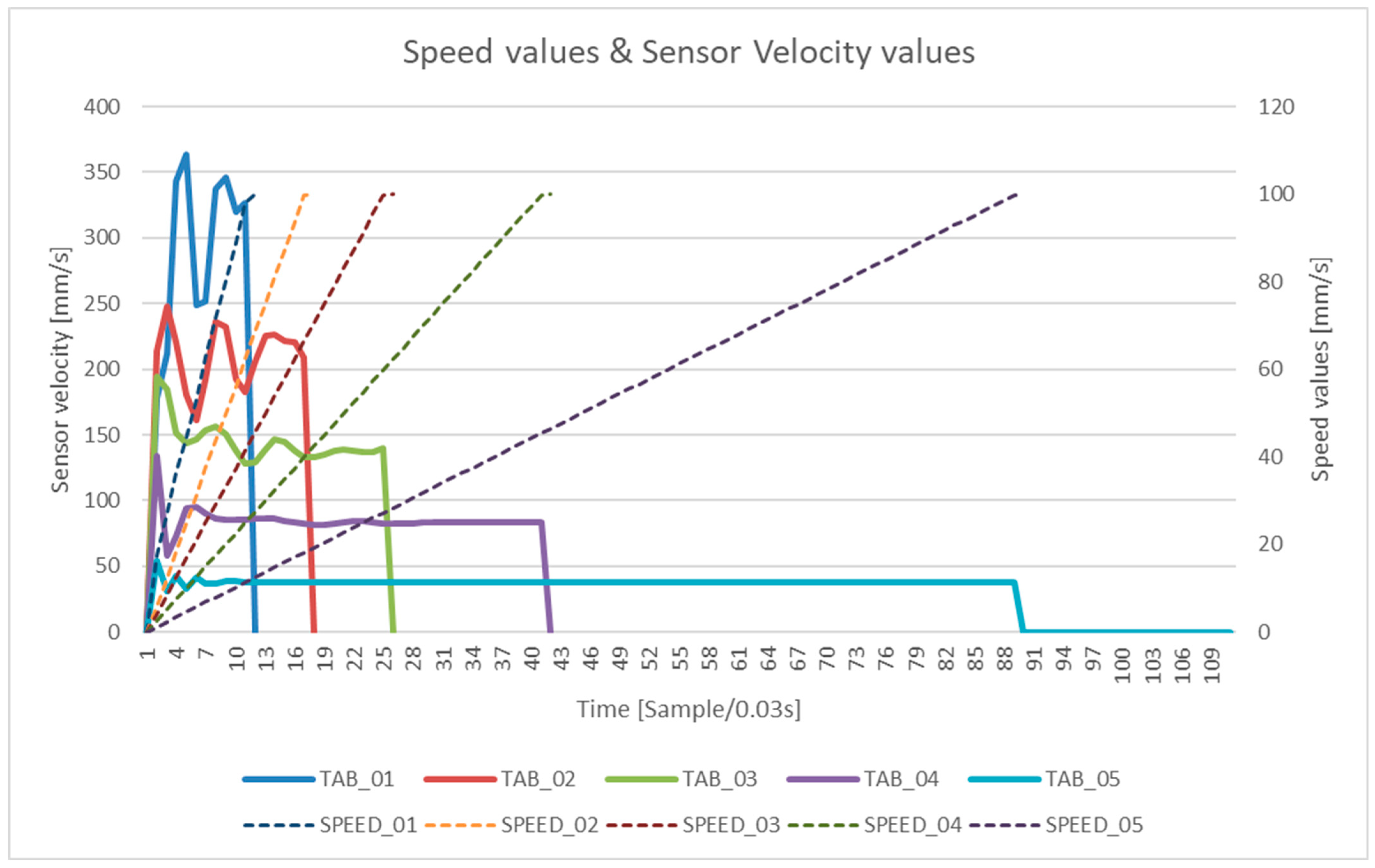
This advanced model included a realistic simulation of the pneumatic system, including airflow, pressure-induced delays, friction, and end-position damping. The desired velocity values in the range of 20 to 100 mm/s (SPEED_01 to SPEED_05) were entered, while the real velocity sensor outputs were recorded (TAB_01 to TAB_05).
The results are shown in
Figure 8, which compares the desired input velocities (dashed lines) with the actual measured values (solid lines).
The chart shows the following:
The real velocity at the beginning of the motion did not immediately reach the desired value but had a characteristic ramp-up curve.
There were slight fluctuations in velocity during the motion, caused by simulated friction, pressure, and system resistances.
Curves TAB_01 to TAB_04 show more pronounced velocity fluctuations, especially in the initial phase of the motion.
TAB_05 in
Figure 9, which represents the lowest required velocity (20 mm/s), achieved a stable waveform, but with a noticeable delay in activation and a short movement time.
These results reflect the behaviour of pneumatic systems, in which the motion is affected by the pressurization time, valve resistance, and inertial properties of the air. In contrast to the previous experiments (1 and 2), more realistic dynamics can be observed here, corresponding to realistic conditions.
4.4. Interpretation of Results
The test results were interpreted with an emphasis on the flexibility of the digital twin in testing different control strategies, along with its ability to adapt to changes in settings. The aim was to verify that the digital twin allows for the reliable simulation of real control scenarios and that it provides sufficient scope to analyse the impact of changes in pneumatic actuator control. The results of the experiments were interpreted to evaluate to what extent the digital twin responds correctly to changes in control inputs and whether it allows for efficient testing of the control algorithms developed in a PLC environment. The interpretation focuses on evaluating the response of the simulated system to different speeds, motion waveforms, and control quality.
4.4.1. Response of Models to Change of Control Parameters
The graphical outputs (
Figure 5,
Figure 6,
Figure 7 and
Figure 8) show that for Experiment 1 (discrete control) and Experiment 2 (analogue control without pneumatic features), the response to a change in the desired speed was accurate, stable, and instantaneous. The simulated system received the speed values from the PLC without delay and executed the corresponding piston displacements in time.
The required values (e.g., 10, 25, 50 mm/s) were correctly interpreted by the model.
The motion was linear, without disturbing effects.
The voltage output from the potentiometer matched the cylinder position, confirming the functional conversion of the control signal to the output data.
This behaviour suggests that these models are suitable for validating basic PLC logic and for simulating systems in which the physical properties of the medium (e.g., air) do not need to be simulated.
4.4.2. Real vs. Desired Speed for Simulated Pneumatic Behaviour
In Experiment 3 (analogue control with simulated pneumatic behaviour), it was found that despite the constant requirements from the PLC (SPEED_01 to SPEED_05), the real motion speed sensed by the sensor (TAB_01 to TAB_05) exhibited ramp delays, slight fluctuations, and deviations from the setpoint (
Figure 8).
The response to the change in speed was not instantaneous but was phase-shifted, which is typical of pneumatic systems.
The resulting velocities were influenced by physical parameters such as pressure, flow, and friction.
This confirms that PLC control must account for the delays and dynamic effects of the system when using this model.
The model has demonstrated a higher fidelity to reality and is therefore suitable for tuning PLC logic that accounts for dynamic system responses—for example, in continuous dosing, contact force control, or safety stop functions.
4.4.3. Stability of Movement at Different Speeds
Interpretation of the time histories shows that the stability of the piston motion depends on the level of detail of the model:
For the simple models (Experiment 1 and 2), the waveform is highly predictable and suitable for testing basic sequences in PLCs without the need to control physical quantities.
In the more complex model (Experiment 3), the waveform is more realistic but at the same time, more challenging to control, opening the possibility for testing the response of the PLC system to realistic conditions (e.g., response to delays, PID controller tunability, etc.).
4.4.4. Response of Models to PLC Inputs and Their Configuration
The results show that all three models can respond to input signals from the PLC, but the following outcomes are noted:
Experiment 1 allows only a binary response (yes/no)—i.e., there is no feedback.
Experiment 2 allows for continuous control, which is ideal for testing the control logic in the PLC (e.g., comparing set and actual position).
Additionally, Experiment 3 allows for the simulation of the behaviour of the system under different conditions, such as pressure or friction changes. The model thus provides a higher level of flexibility when verifying the behaviour of PLC programs in real production scenarios.
5. Discussion
The results of the interpreted simulations showed differences in the dynamics of the pneumatic cylinder piston motion, depending on the type of digital twin model implemented and the control strategy. Three different approaches were tested—discrete control, analogue control without physical properties, and analogue control with simulated pneumatic behaviour. This discussion compares their advantages, limitations, and context with the behaviour of the real pneumatic system described in the study of Jiménez et al. [
43].
The results of Experiment 3 show that a realistic simulation of the pneumatic behaviour allows for the capture of the latent phase of the piston motion that occurs before the static frictional force is exceeded.
This phenomenon was also observed in the work of Jiménez, where the static frictional force was identified as the main factor of the motion delay—i.e., the difference between the time of signal activation and the moment of the start of the real displacement. In our results, the motion delay varied as a function of the input pressure and exactly reproduced the different dynamics—at higher pressures, the motion was faster, with a shorter latency phase.
This behaviour confirms that models simulating pressure and airflow (e.g., Experiment 3) can realistically replicate physical phenomena such as rise time delay, air compressibility, valve resistance, and the effect of backpressure, which is consistent with the findings of Jiménez [
43], in which measured upstream/downstream pressure was used to calculate the actual force and identify the moment of motion.
Simulations with discrete control (Experiment 1) revealed significant fluctuations in the velocity profile, which was due to the absence of flow control and abrupt changes during valve switching. This instability corresponds to the realistic behaviour of simple electro-pneumatic systems without feedback control, where the velocity is not regulated by the control algorithm but by passive components such as the throttling valve.
In the Jiménez study, similar fluctuations in velocity were identified at lower pressures and in cases where active control was not used. High-frequency measurements also revealed irregularities during ramp-up and deceleration that arise due to nonlinear valve dynamics and pressure fluctuations. Our results for analogue control with simulated physics captured these fluctuations, especially during the transition between active and passive phases of motion, confirming the suitability of this model for dynamic analyses.
The discrete model has demonstrated its suitability for testing sequential logic where precise rate control is not required. The results showed that such a model has a fast response but a low predictive value, as it does not account for the physical properties of the actuator. An analogue model without pneumatic properties allowed for the testing of the control using analogue inputs, but the response was too ideal.
Only the third model—with simulated pneumatic behaviour—showed dynamics corresponding to those of real actuators. In agreement with the work of Jiménez, in which it was confirmed by measurement that the piston velocity is approximately constant in the main part of the stroke, our results showed the same behaviour—after the initial friction phase is overcome, a stable motion occurs, the duration of which is dependent on the input pressure.
As part of the experimental validation, three different control models for the digital twin of the electro-pneumatic actuator were tested to assess their accuracy, flexibility, implementation complexity, and suitability for testing PLC algorithms.
The first model was a discrete control (ON/OFF), in which the valve is controlled by binary “open” and “close” signals. This approach is very simple to implement and allows for direct connection to the PLC without the need for additional interfaces. It exhibits the disadvantage of low accuracy, as it does not consider any physical properties of the actuator, nor does it allow for the control of the speed of movement.
The second model was an analogue control with no physical characteristics, where the motion of the cylinder was controlled through analogue inputs and outputs, but with no simulation of pneumatic effects. This model was created as a standard mechanical model in the NX MCD environment. It allows for more accurate speed control and smooth motion but still does not account for the dynamics of a real pneumatic system, such as delays, friction, or pressure changes.
The third and most complex model was the one with analogue control and simulated pneumatic behaviour, which realistically represents pressure dynamics, flow, time delays, friction, and end-position damping. This model was developed through the integration of NX MCD and SIMIT, with SIMIT responsible for simulating the pneumatic dynamics and enabling the interface with the PLC via OPC UA.
Although this configuration required increased computational resources and more advanced software integration, it offered the highest level of physical fidelity among all the tested scenarios. The model was executed on a workstation equipped with an Intel® Core™ i7-9700 CPU @ 3.00 GHz, 16 GB of RAM, an NVIDIA Quadro P2200 GPU (5 GB VRAM), and a 64-bit Windows 11 Pro operating system, ensuring compatibility with the combined use of NX MCD 2412, SIMIT V10.3, and PLCSIM Advanced for software-in-the-loop simulation.
The introduction of a digital twin with control emulation in SIMIT and interfacing with the PLC created an efficient environment for testing algorithms without the need for a physical system. Compared to the study of Jiménez [
43], in which specialized equipment such as dSPACE and pressure sensors were used to measure real pneumatic phenomena, our approach offers the advantages of fast configuration, secure testing, and repeatability.
By comparing all three models (
Table 5), trade-offs between ease of implementation, computational complexity, and simulation accuracy can be identified. The results show that the choice of a model depends on the specific purpose—whether it is to validate the underlying logic, to test the control, or to obtain a faithful physical simulation.
This methodology contributes to a more efficient design of the digital twins of electropneumatic actuators, allows for optimization of the PLC algorithms before their deployment, and increases the overall flexibility of development within industrial automation.
These findings further emphasise that when the goal is to simulate the physical behaviour of pneumatic systems with high fidelity, the software infrastructure becomes noticeably more complex. As shown by the third model, achieving a realistic simulation of time delays, pressure dynamics, and friction requires integrating advanced tools like SIMIT. This confirms a key contribution of the research: higher simulation accuracy comes at the cost of increased implementation complexity.
In addition, initial tests with dynamic loads in the NX MCD environment revealed gradual simulation delays, likely due to high CPU and GPU usage. This suggests that the computational demand can become a limiting factor when physical accuracy is combined with complex interactions. This will be subject to further investigation, as it may influence the scalability and responsiveness of digital twin systems in real-time applications.
These challenges clearly illustrate that elaborated digital twins impose non-trivial demands on the future of process automation. From computational load to integration complexity, such systems require a careful balance between simulation fidelity and practical feasibility in industrial environments.
On the other hand, the ability to run simulation scenarios quickly and to debug control programs without physical hardware provides a significant advantage, making the development process faster, safer, and more flexible.
6. Conclusions
The results of this study confirm that a digital twin of a pneumatic cylinder, created in the NX MCD environment and augmented with realistic dynamic properties using SIMIT, provides a faithful representation of the behaviour of the real system. By comparing three different control strategies—ranging from simple ON/OFF control to the simulation of pneumatic properties—it was possible to identify differences in system response, accuracy, and suitability for testing PLC algorithms.
The simplest model allowed for the testing of the basic sequential logic, while the model with simulated pneumatic behaviour showed the highest level of fidelity to the real actuator behaviour. The results correspond with experimental findings published in the literature, especially regarding the latent phase of motion, fluctuations under uncontrolled actuation, and the influence of the input pressure on the system dynamics.
In the next phase of the research, it is planned to link the developed control algorithm with a real electro-pneumatic cylinder, with the aim of comparing the simulated outputs with real measurements. This step will allow for the experimental verification of the accuracy of the model, the evaluation of the influence of non-ideal conditions, and the establishment of a basis for possible modifications in the control software. The results will thus contribute not only to the validation of the digital twin, but also to the optimization of control strategies in industrial environments.
In addition to assessing simulation accuracy, this study also highlights an important implication for the future of process automation: implementing a high-fidelity digital twin requires advanced and often complex software infrastructure. This includes managing the integration of tools like NX MCD and SIMIT, as well as ensuring real-time performance under computational load. Initial experiments with dynamic loading in NX MCD revealed simulation delays likely caused by CPU and GPU saturation—a challenge that will be explored in future research.
Nevertheless, the ability to rapidly run simulation scenarios and debug control programs without physical hardware offers significant advantages. It speeds up development, improves safety during testing, and provides a flexible platform for the iterative refinement of industrial automation systems.
Author Contributions
Conceptualization, R.R., T.H., R.S., and M.K.; methodology, R.R., T.H., R.Z., and E.N.; validation, R.R., T.H., R.S., J.Š., and M.C.; formal analysis, T.H., R.R., M.K., M.C., and E.N.; investigation, R.R., R.Z., and R.S.; resources, R.R., T.H., M.C., J.Š., and M.K.; writing—original draft preparation, R.R., T.H., R.S., R.Z., and M.C.; writing—review and editing, E.N. and M.K.; visualization, R.R., T.H., and R.Z.; supervision, R.R., R.Z., and M.K.; funding acquisition, R.R., M.C., and T.H. All authors have read and agreed to the published version of the manuscript.
Funding
This research was funded by the Scientific Grant Agency of the Ministry of Education, Science, Research, and Sport of the Slovak Republic and the Slovak Academy of Sciences, grant number VEGA 1/0391/24, Research and Development of Sensor Calibration Methodology for Diagnostic Equipment for Automated and Robotic Systems; by a call for doctoral students and young researchers of the Slovak University of Technology in Bratislava to start a research career (project ESG 23-06-01-B, Design and Implementation of the Security of Industrial Network Systems with the Creation of a Standardized Data Set for Security Analyses (NAIZPSS)); by the Scientific Grant Agency of the Ministry of Education, Science, Research, and Sport of the Slovak Republic and the Slovak Academy of Sciences, grant number VEGA 1/0175/25, Applying Machine Learning and Digital Fingerprinting to Improve Detection and Mitigation of DDoS Attacks; and by the Scientific Grant Agency of the Ministry of Education, Science, Research, and Sport of the Slovak Republic and the Slovak Academy of Sciences, grant number KEGA 004TU Z-4/2024, Implementation of Progressive Methods of Education in Professional Subjects in the Field of Mechanical Engineering and Industrial Robotics.
Data Availability Statement
The data are contained within the article.
Conflicts of Interest
The authors declare no conflicts of interest.
Abbreviations
The following abbreviations are used in this manuscript:
| HIL | Hardware-in-the-Loop |
| M2M | Machine-to-Machine |
| MIL | Model-in-the-Loop |
| NX MCD | NX Mechatronics Concept Designer |
| OPC UA | Open Platform Communications Unified Architecture |
| PID | Proportional–Integral–Derivative |
| PLC | Programmable Logic Controller |
| SIL | Software-in-the-Loop |
| TIA Portal | Totally Integrated Automation Portal |
References
- Longo, F.; Padovano, A.; Solina, V.; Mirabelli, G.; Liu, J.; Zhang, K. Design and Simulation Debugging of Automobile Connecting Rod Production Line Based on the Digital Twin. Appl. Sci. 2023, 13, 4919. [Google Scholar] [CrossRef]
- Misyurin, S.Y.; Kreinin, G.V.; Nosova, N.Y. Digital Twin of the Drive System, Considering the Forces of Various Nature. Procedia Comput. Sci. 2021, 190, 611–621. [Google Scholar] [CrossRef]
- Chlebek, J.; Kot, T.; Oscadal, P.; Heczko, D.; Maslowski, J.; Scalera, L.; Vysocky, A. Optimized Grid Voxelization for Obstacle Avoidance in Collaborative Robotics. IEEE Access 2025, 13, 45187–45197. [Google Scholar] [CrossRef]
- Marcinko, P.; Semjon, J.; Jánoš, R.; Svetlík, J.; Sukop, M.; Ondočko, Š. Analysis of the Methodology for Experimental Measuring of the Performance Criteria of the Laser-Using Collaborative Robot’s Path Accuracy. Appl. Sci. 2024, 14, 1414. [Google Scholar] [CrossRef]
- Kováč, J.; Malega, P.; Svetlík, J. Smart Electric Three-Wheeled Unit for the Manufacturing Industry. Appl. Sci. 2024, 14, 4933. [Google Scholar] [CrossRef]
- Fedorko, G.; Mikušová, N.; Čabaníková, L.; Vasiľ, M.; Ondič, P. Simulation in the Digital Factory: A Case Study. Adv. Sci. Technology. Res. J. 2025, 19, 16–27. [Google Scholar] [CrossRef]
- Gunes, V. A Digital Twin Design Methodology for Control, Simulation, and Monitoring of Fluidic Circuits. Int. J. Adv. Manuf. Technol. 2024, 134, 3863–3875. [Google Scholar] [CrossRef]
- Stegmaier, V.; Schaaf, W.; Jazdi, N.; Weyrich, M. Simulation Model for Digital Twins of Pneumatic Vacuum Ejectors. Chem. Eng. Technol. 2023, 46, 71–79. [Google Scholar] [CrossRef]
- Sokolov, O.; Hosovsky, A.; Ciszak, O.; Ivanov, V.; Pavlenko, I. A Digital Twin of the Soft Robot with a Pneumatic Muscle Actuator. In Intelligent Systems in Production Engineering and Maintenance III. ISPEM 2023; Springer: Cham, Switzerland, 2024; pp. 280–292. [Google Scholar] [CrossRef]
- Strahilov, A.; Damrath, F. Simulation of the Behavior of Pneumatic Drives for Virtual Commissioning of Automated Assembly Systems. Robot. Comput. Integr. Manuf. 2015, 36, 101–108. [Google Scholar] [CrossRef]
- Tao, Z.; Li, Y. Research on High Precision Real-Time Digital Twin Model. In Proceedings of the 2024 8th International Conference on Electrical, Mechanical and Computer Engineering, ICEMCE 2024, Xi’an, China, 25–27 October 2024; pp. 1714–1718. [Google Scholar] [CrossRef]
- Yu, H.; Liu, X.; Yang, Z.; Wang, S.; Hao, L. A Finite Element Method and Gaussian Process Based Digital Twin Prototype for Pneumatic Soft Actuator with Experiment Validation. In Proceedings of the 13th IEEE International Conference on CYBER Technology in Automation, Control, and Intelligent Systems, CYBER 2023, Qinhuangdao, China, 11–14 July 2023; pp. 951–955. [Google Scholar] [CrossRef]
- Folgado, F.J.; Calderón, D.; González, I.; Calderón, A.J. Review of Industry 4.0 from the Perspective of Automation and Supervision Systems: Definitions, Architectures and Recent Trends. Electronics 2024, 13, 782. [Google Scholar] [CrossRef]
- Li, Z.; Huang, Y.; Liu, F.; Zhang, J. Motion Simulation and Optimization of LED Chip Scanning and Positioning Based on NX MCD. In Proceedings of the 2024 5th International Conference on Mechatronics Technology and Intelligent Manufacturing, ICMTIM 2024, Nanjing, China, 26–28 April 2024; pp. 345–349. [Google Scholar] [CrossRef]
- Liu, K.; Zhang, Z.; Wu, B.; Wu, Z. NX MCD-Based Unboxing Machine Model Design and Virtual Commissioning. In Proceedings of the 2023 IEEE 16th International Conference on Electronic Measurement and Instruments, ICEMI 2023, Harbin, China, 9–11 August 2023; pp. 179–183. [Google Scholar] [CrossRef]
- Ionescu, D.; Filipescu, A.; Simion, G.; Solea, R.; Serbencu, A. PLC Inverse Kinematics Model-Driven Digital Twin Focused on HIL for a Flexible Robotic Cell. In Proceedings of the 2024 18th International Conference on Control, Automation, Robotics and Vision, ICARCV 2024, Dubai, United Arab Emirates, 12–15 December 2024; pp. 1195–1200. [Google Scholar] [CrossRef]
- Lacasa, A.; Llopis, J.; Montés, N.; Peinado-Asensi, I.; Garcia, E. Cross-PLC: An I3oT Cross Platform to Manage Communications for Applications in Real Factories. Sensors 2025, 25, 2973. [Google Scholar] [CrossRef] [PubMed]
- Vagas, M.; Majercak, O.; Galajdova, A.; Rakay, R.; Romancik, J. Data Processing Approach Based on OPC UA Architecture Implementation and Bluebird Platform. IEEE Access 2025, 13, 51069–51084. [Google Scholar] [CrossRef]
- Strahilov, A.; Effmert, D.; Other, A.N. Simulation of the Pneumatic Behavior in the Virtual Commissioning of Automated Assembly Systems. Lect. Notes Mech. Eng. 2013, 7, 207–218. [Google Scholar] [CrossRef]
- Bysko, S.; Bysko, S.; Fratczak, M.; Nowak, P.; Klopot, T.; Czeczot, J.; Stebel, K.; Laszczyk, P. PID Controller Tuning by Virtual Commissioning—A Step to Industry 4.0. J. Phys. Conf. Ser. 2022, 2198, 012010. [Google Scholar] [CrossRef]
- Konstantinov, S.; Assad, F.; Ahmad, B.; Vera, D.A.; Harrison, R. Virtual Engineering and Commissioning to Support the Lifecycle of a Manufacturing Assembly System. Machines 2022, 10, 939. [Google Scholar] [CrossRef]
- Lyu, T.; Atmojo, U.D.; Vyatkin, V. Towards Virtual Commissioning Environment for Smart Mechatronic Systems. In Proceedings of the 2024 IEEE 18th International Conference on Advanced Motion Control (AMC), Kyoto, Japan, 28 February–1 March 2024; pp. 1–6. [Google Scholar] [CrossRef]
- Lyu, T.; Lashchev, A.; Patil, S.; Atmojo, U.D.; Vyatkin, V. Mechatronic Swarm and Its Virtual Commissioning. In Proceedings of the 2023 IEEE International Conference on Mechatronics, ICM 2023, Loughborough, UK, 15–17 March 2023. [Google Scholar] [CrossRef]
- Vermaak, H.; Niemann, J. Virtual Commissioning: A Tool to Ensure Effective System Integration. In Proceedings of the 2017 IEEE International Workshop of Electronics, Control, Measurement, Signals and their Application to Mechatronics, ECMSM 2017, Donostia, Spain, 24–26 May 2017. [Google Scholar] [CrossRef]
- Faller, C.; Smajic, H. Design and Development of a Virtual 3D Twin for Smart Automation; Hochschule für Technik, Wirtschaft und Kultur Leipzig: Leipzig, Germany, 2023. [Google Scholar] [CrossRef]
- Antonelli, M.G.; Brunetti, J.; D’Ambrogio, W.; Fregolent, A.; Nataletti, P. Development of a Digital Twin for a Hydraulic, Active Seat Suspension System. Machines 2023, 11, 708. [Google Scholar] [CrossRef]
- Aydemir, H.; Zengin, U.; Kruschinski, D.; Hartmann, S.; Durak, U. Developing a Virtual Actuator as a Digital Twin. In Proceedings of the AIAA AVIATION 2022 Forum, Chicago, IL, USA, 27 June–1 July 2022. [Google Scholar] [CrossRef]
- Ciganek, J.; Zemla, F. Design of Digital Twin for PLC System. In Proceedings of the 31st International Conference on Cybernetics and Informatics, K and I 2022, Visegrád, Hungary, 11–14 September 2022. [Google Scholar] [CrossRef]
- Xiong, L.; He, Y.; Chen, Y.; Lu, J.; Niu, G. Digital Twin-Based Degradation Prediction for Train Electro-Pneumatic Valve. Reliab. Eng. Syst. Saf. 2023, 240, 109627. [Google Scholar] [CrossRef]
- Giordano, R. Development of a Digital Twin for the Validation of Prognostic Algorithms for Electromechanical Actuators. Doctoral Dissertation, Politecnico di Torino, Turin, Italy, 2021. [Google Scholar]
- Smid, R. Digital Twin for Condition Monitoring of Actuators. In Proceedings of the 19th International Conference on Condition Monitoring and Asset Management, CM 2023, Northampton, UK, 12–14 September 2023. [Google Scholar] [CrossRef]
- Damrath, F.; Strahilov, A.; Bär, T.; Vielhaber, M. Experimental Validation of a Physics-Based Simulation Approach for Pneumatic Components for Production Systems in the Automotive Industry. Procedia CIRP 2015, 31, 35–40. [Google Scholar] [CrossRef]
- Yu, Y.; Gao, S.C.; Cao, Y.N.; Liu, J.X.; Jiao, Z.W. Digital Twin Design of Pneumatic Classifier and Its Key Technology. J. Phys. Conf. Ser. 2023, 2589, 012028. [Google Scholar] [CrossRef]
- Trentini, R.; Rafael, D.; Yuri, S.; Ferreira, R. A Comprehensive Mathematical Model of a Low-Friction Servopneumatic Actuator. arXiv 2020, arXiv:2011.06659. [Google Scholar]
- Faltus, O.; Horák, M.; Doškář, M.; Rokoš, O. Third Medium Finite Element Contact Formulation for Pneumatically Actuated Systems. Comput. Methods Appl. Mech. Eng. 2024, 431, 117262. [Google Scholar] [CrossRef]
- Žemla, F.; Cigánek, J. View of The Programmable Virtual Model of the Mechatronic System Using NX 12 Environment | Information Technology Applications. Int. J. Inf. Technol. Appl. (ITA) 2022, 11, 3–14. [Google Scholar]
- Li, M.; Yang, D. Design of a Material Sorting Digital Twin System Based on NX MCD. Manuf. Rev. 2024, 11, 13. [Google Scholar] [CrossRef]
- Miseo, F.P. Virtual Commissioning of a Pneumatic Servosystem with a PLC in MIL, SIL, and HIL. Doctoral Dissertation, Politecnico di Torino, Turin, Italy, 2019. [Google Scholar]
- ISO 15552:2018; Pneumatic fluid power—Cylinders with detachable mountings, 1000 kPa (10 bar) series, bores from 32 mm to 320 mm — Basic, mounting and accessories dimensions. International Organization for Standardization: London, UK, 2018.
- Parr, A. Hydraulics and Pneumatics: A Technician’s and Engineer’s Guide; Butterworth-Heinemann: Oxford, UK, 2011; ISBN 9780080966748. [Google Scholar]
- Esposito, A. Fluid Power with Applications; Prentice-Hall Inc.: New York, NY, USA, 1980; ISBN 0133227014. [Google Scholar]
- Cantwell, B.J. Fundamentals of Compressible Flow; Stanford University: Stanford, CA, USA, 2022. [Google Scholar]
- Jiménez, M.; Kurmyshev, E.; Castañeda, C.E. Experimental Study of Double-Acting Pneumatic Cylinder. Exp. Tech. 2020, 44, 355–367. [Google Scholar] [CrossRef]
Figure 1.
Overview of the methodological framework used for the development, integration, and validation of the digital twin of an electro-pneumatic actuator. The process includes the design of the 3D and behavioural model in NX MCD, integration with the PLC environment via PLCSIM Advanced, the OPC UA communication setup using SIMIT, control logic implementation, and the comparison of different model configurations. The diagram also highlights the bidirectional data flow and iterative testing cycles essential for reliable virtual commissioning.
Figure 2.
The standardized ISO 15552 double-acting cylinder DSBC-32-100-PPSA-N3 used for the subject of investigation and digital twin formation.
Figure 2.
The standardized ISO 15552 double-acting cylinder DSBC-32-100-PPSA-N3 used for the subject of investigation and digital twin formation.
Figure 3.
Transfer of a 3D model created with the Festo Design Tool 3D and exported in NX prt format.
Figure 3.
Transfer of a 3D model created with the Festo Design Tool 3D and exported in NX prt format.
Figure 4.
Imported information into NX Mechatronics Concept Designer, including the creation of a physics and kinematics model for the digital twin.
Figure 4.
Imported information into NX Mechatronics Concept Designer, including the creation of a physics and kinematics model for the digital twin.
Figure 5.
Signal flow diagram of the co-simulation architecture using OPC UA communication: SIMIT acts as the OPC UA server providing simulated signals, while PLCSIM Advanced and NX MCD operate as OPC UA clients to execute control logic and simulate the behaviour of a pneumatic actuator. This configuration enables closed-loop testing of a digital twin, where the physical actuator’s dynamics are virtually emulated and synchronised with the PLC program in real time.
Figure 6.
Piston speed profiles at set input speeds (DATA_10 to DATA_100).
Figure 6.
Piston speed profiles at set input speeds (DATA_10 to DATA_100).
Figure 7.
Time history of piston displacement for different speeds.
Figure 7.
Time history of piston displacement for different speeds.
Figure 8.
Output from the potentiometer when the piston moves (0–100 mm = 0–10 V).
Figure 8.
Output from the potentiometer when the piston moves (0–100 mm = 0–10 V).
Figure 9.
Comparison of the required input speeds (SPEED_01 to SPEED_05) with real sensor-measured piston speed values (TAB_01 to TAB_05) for analogue control with simulated pneumatic behaviour.
Figure 9.
Comparison of the required input speeds (SPEED_01 to SPEED_05) with real sensor-measured piston speed values (TAB_01 to TAB_05) for analogue control with simulated pneumatic behaviour.
Table 1.
Specifications of the pneumatic cylinder DSBC-32-100-PPSA-N3.
Table 1.
Specifications of the pneumatic cylinder DSBC-32-100-PPSA-N3.
| Parameter | Value |
|---|
| Bore diameter | 32 mm |
| Stroke | 100 mm |
| Operation | Double-acting |
| Piston rod thread | M10×1.25 (external) |
| Mounting position | Any |
| Cushioning | Self-adjusting pneumatic end-position |
| Operating pressure | 0.06 MPa to 1.2 MPa (0.6 to 12 bar) |
| Medium | Compressed air (ISO 8573-1:2010 [7:4:4]) |
| Max impact energy at end positions | 0.4 J |
| Cushioning length | 17 mm |
| Theoretical force (6 bar, extend) | 483 N |
| Theoretical force (6 bar, retract) | 415 N |
| Position sensing | For contactless sensors |
| Standards compliance | ISO 15552, LABS VDMA24364-B1/B2-L |
| Temperature range | −20 °C to +80 °C |
| Weight (at 0 mm stroke) | 465 g |
| Total product weight | 735 g |
| Tube material | Aluminium alloy, anodized |
| Piston rod material | High-alloy steel |
| Seal material | TPE-U(PU) |
Table 2.
Signals in NX MCD digital twin, Experiment 1.
Table 2.
Signals in NX MCD digital twin, Experiment 1.
| Name | Type | Parameters | Signal Name | Data Type | I/O Type |
|---|
| 1B1 | Limit Switch | Position 0.5 mm | Close | Bool | Output |
| 1B2 | Limit Switch | Position 99.5 mm | Open | Bool | Output |
| piston_discrete | Position Control | Destination 0 mm | 1MB1 | Bool | Input |
| piston_discrete | Position Control | Destination 100 mm | 1MB2 | Bool | Input |
| piston_discrete | Position Control | Speed 0–400 mm/s | get_speed | Double | Input |
| Positionsensor | Positionsensor 0–100 mm | 0–10 V | Potentiometer | Double | Output |
| Velocitysensor | Velocitysensor 0–400 mm/s | 0–400 | Speed | Double | Output |
Table 3.
Signals in NX MCD digitalt, Experiment 2.
Table 3.
Signals in NX MCD digitalt, Experiment 2.
| Name | Type | Parameters | Signal Name | Data Type | I/O Type |
|---|
| piston_analog | Position Control | 0–100 mm | get_position | Bool | Input |
| piston_analog | Position Control | Speed 0–400 mm/s | get_speed | Double | Input |
| Positionsensor | Positionsensor 0–100 mm | 0–10 V | Potentiometer | Double | Output |
| Velocitysensor | Velocitysensor 0–400 mm/s | 0–400 | Speed | Double | Output |
Table 4.
Signals in NX MCD digital twin, Experiment 3.
Table 4.
Signals in NX MCD digital twin, Experiment 3.
| Name | Type | Parameters | Signal Name | Data Type | I/O Type |
|---|
| 1B1 | Limit Switch | Position 0.5 mm | Close | Bool | Output |
| 1B2 | Limit Switch | Position 99.5 mm | Open | Bool | Output |
| pneu_act | Pneumatic Cylinder | Double Rod | 1MB1 | Bool | Input |
| pneu_valve | Pneumatic Valve | 2pos4port | 1MB2 | Bool | Input |
| piston_discrete | Position Control | Speed 0–400 mm/s | get_speed | Double | Input |
| Positionsensor | Positionsensor 0–100 mm | 0–10 V | Potentiometer | Double | Output |
| pneu_valve | Pneumatic Valve | Supply Pressure A 600 kPa | supply_pressureA | Double | Input |
| pneu_valve | Pneumatic Valve | Supply Pressure B 600 kPa | supply_pressureB | Double | Input |
Table 5.
Overview of control models in NX MCD: speed control, implementation complexity, and software infrastructure.
Table 5.
Overview of control models in NX MCD: speed control, implementation complexity, and software infrastructure.
| Model | Speed Control Option | Implementation Complexity | Software Infrastructure |
|---|
| Discrete control | No | Simple | PLC + NX MCD minimal |
| Analogue control | Yes | Middle | PLC + NX MCD minimal |
| Pneumatic control | Yes | Complex | PLC + SIMIT + NX MCD |
| Disclaimer/Publisher’s Note: The statements, opinions and data contained in all publications are solely those of the individual author(s) and contributor(s) and not of MDPI and/or the editor(s). MDPI and/or the editor(s) disclaim responsibility for any injury to people or property resulting from any ideas, methods, instructions or products referred to in the content. |
© 2025 by the authors. Licensee MDPI, Basel, Switzerland. This article is an open access article distributed under the terms and conditions of the Creative Commons Attribution (CC BY) license (https://creativecommons.org/licenses/by/4.0/).


 ,
, 


