
Online Sensing of Thermal Deformation in Complex Space Bulkheads Driven by Temperature Field Measurements


Abstract
1. Introduction
- A restructuring strategy based on the geometric invariance of the bulkhead is proposed, which decouples the time-consuming stiffness matrix assembly and inversion process from the conventional FEM, thereby enabling FEM-based online computation.
- A data-driven temperature field reconstruction technique is introduced, which allows for fast and accurate capture of full-field temperature distributions. This not only ensures the real-time performance of thermal deformation prediction but also improves its accuracy.
2. Methodology
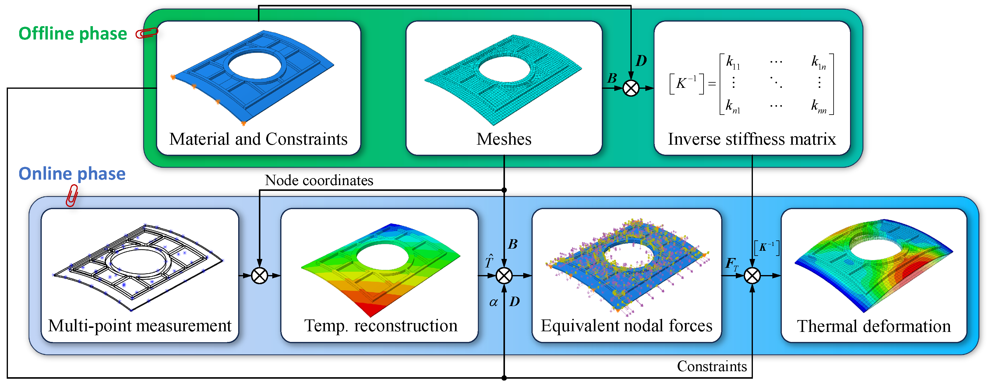
- Offline phase: (a) Construct a finite element model for purely static analysis. (b) Assemble the inverse stiffness matrix incorporating the mesh, material properties, and constrained degrees of freedom (DOFs).
- Online phase: (a) Reconstruct the temperature field based on multi-sensor measurements. (b) Convert the temperature field into equivalent nodal forces, which are then applied as boundary conditions. (c) Solve the linear system of equations using the inverse stiffness matrix to obtain the thermal deformation.
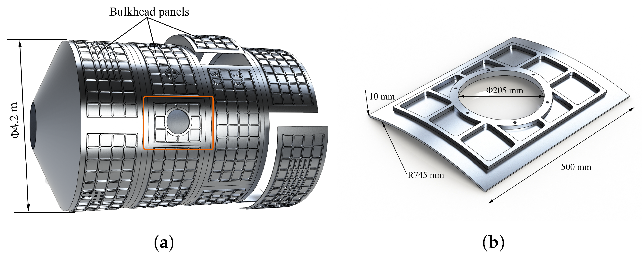
2.1. Finite Element Modeling for Static Analysis
2.2. Temperature Field Reconstruction Based on Multi-Sensors
2.3. Online Solution of Thermal Displacements
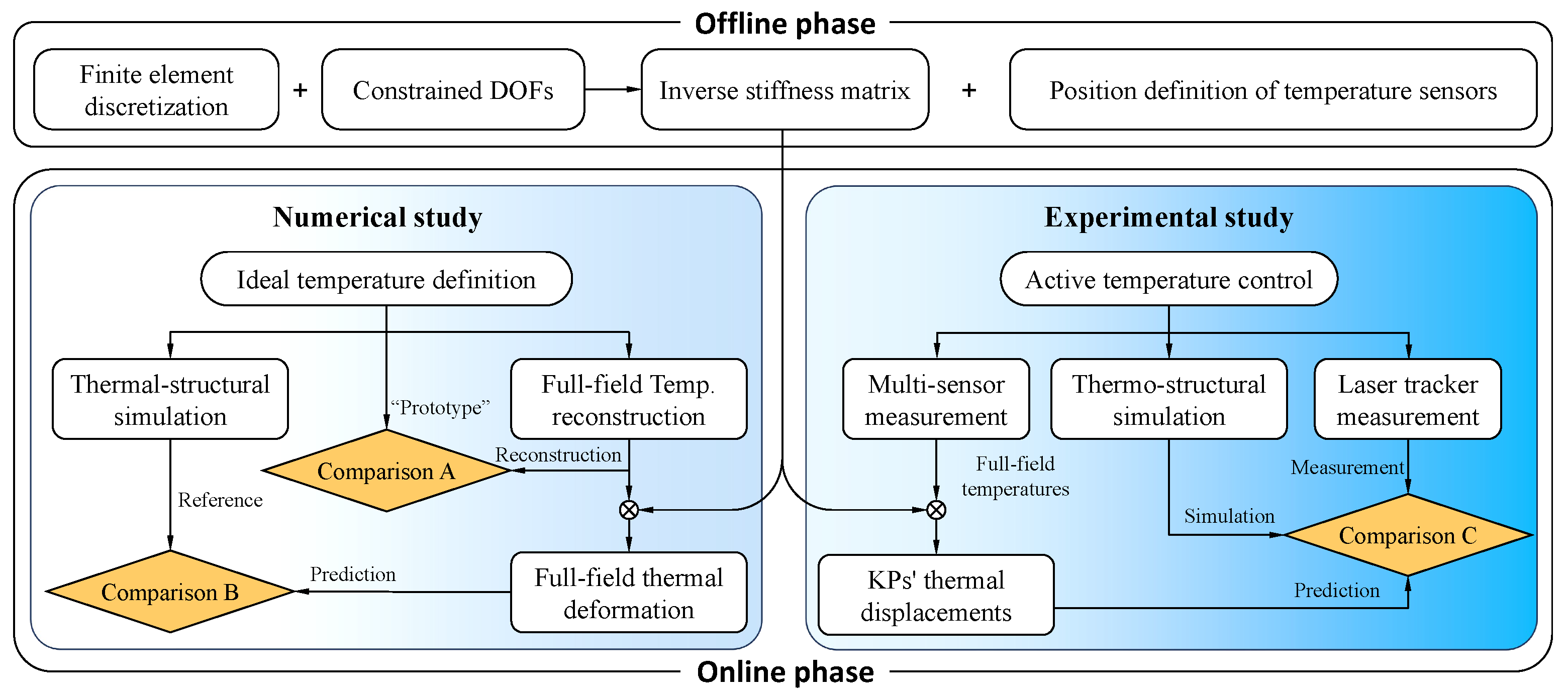
3. Numerical and Experimental Investigation
3.1. Offline Phase
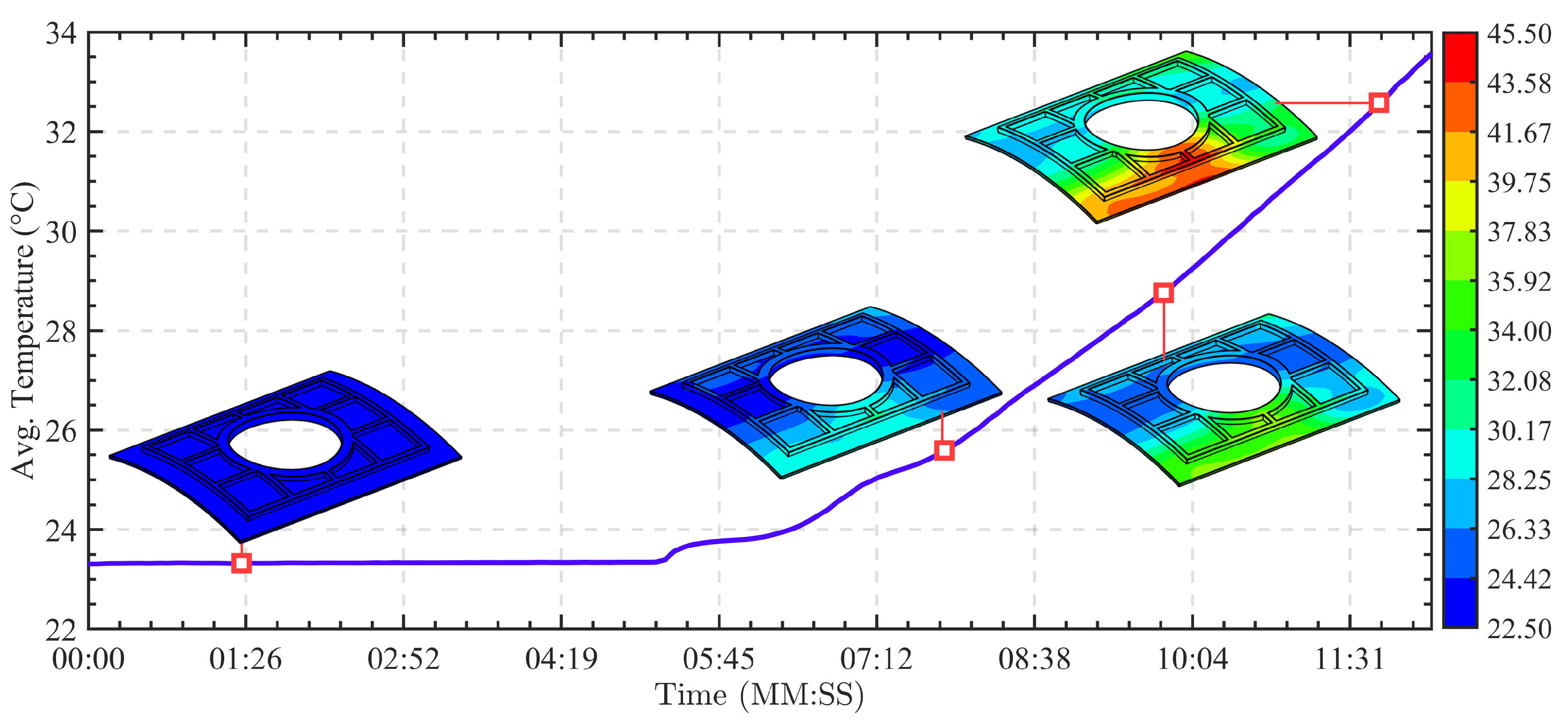
3.2. Online Phase
3.2.1. Numerical Validation
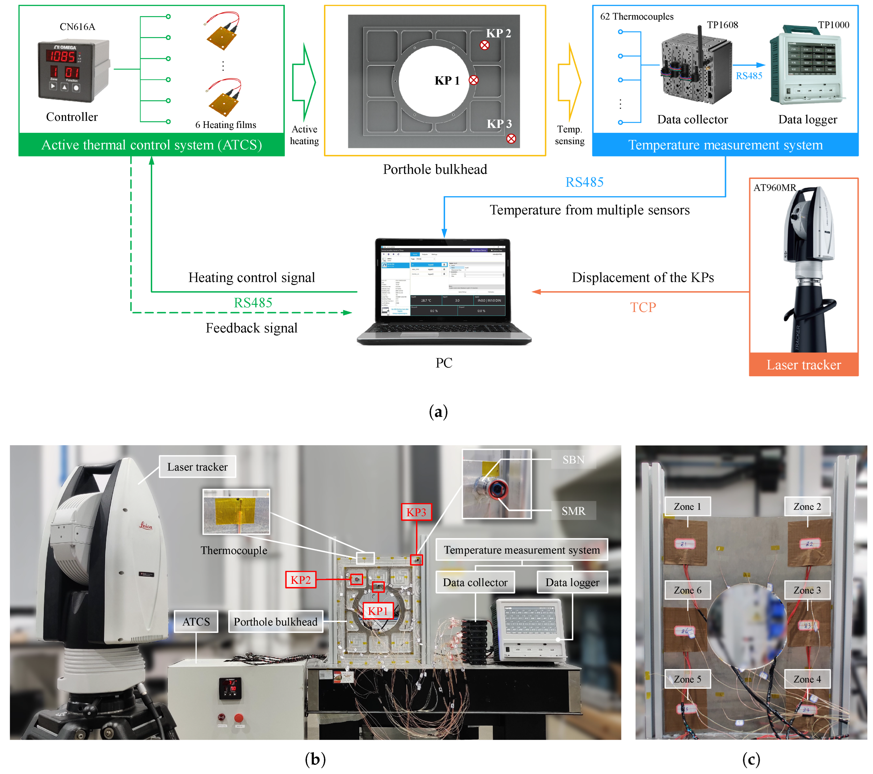
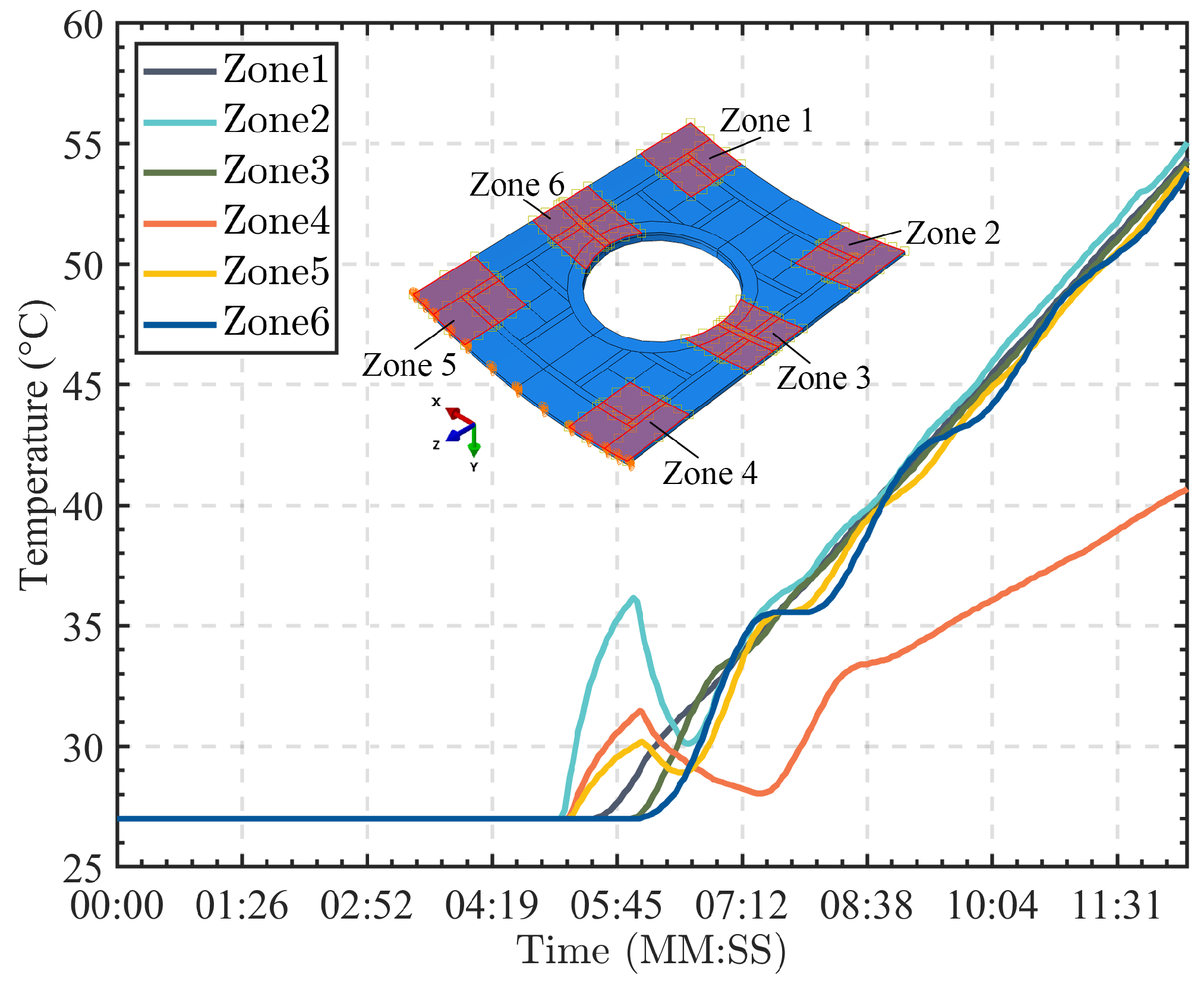
3.2.2. Experimental Validation
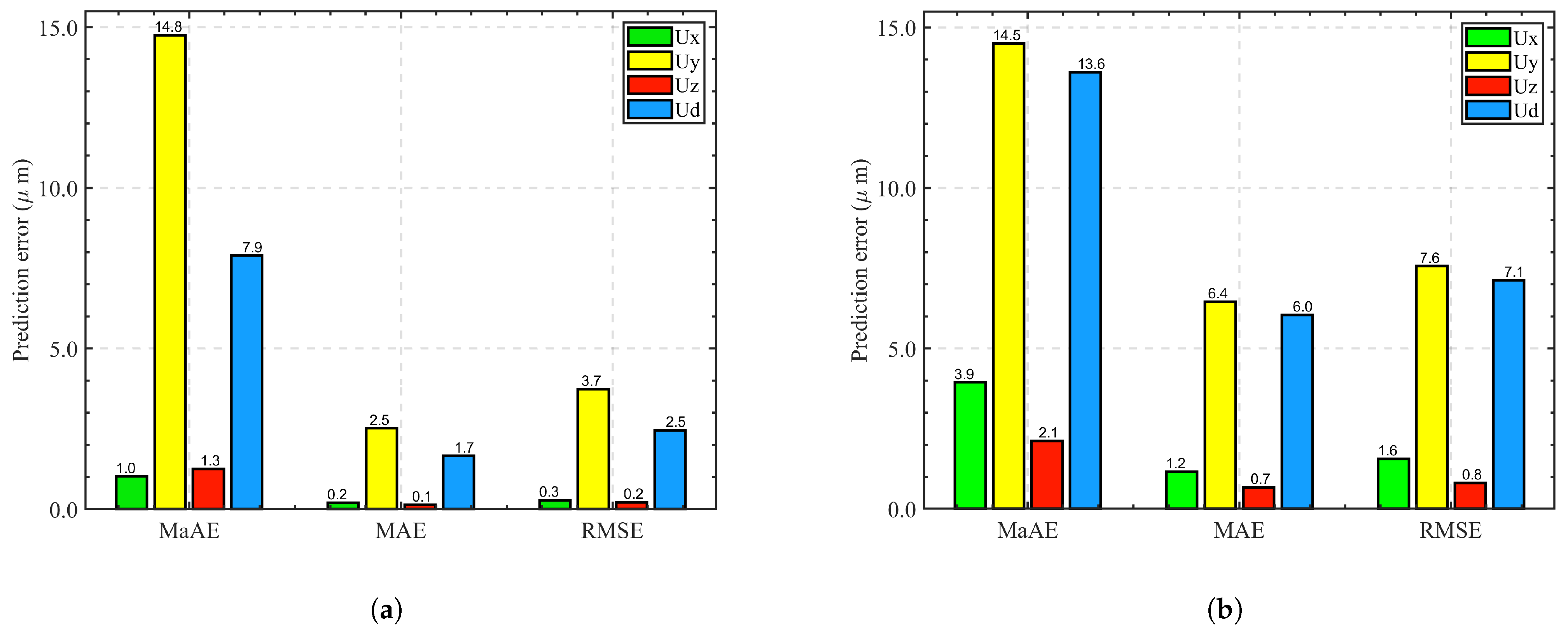
4. Results and Discussion
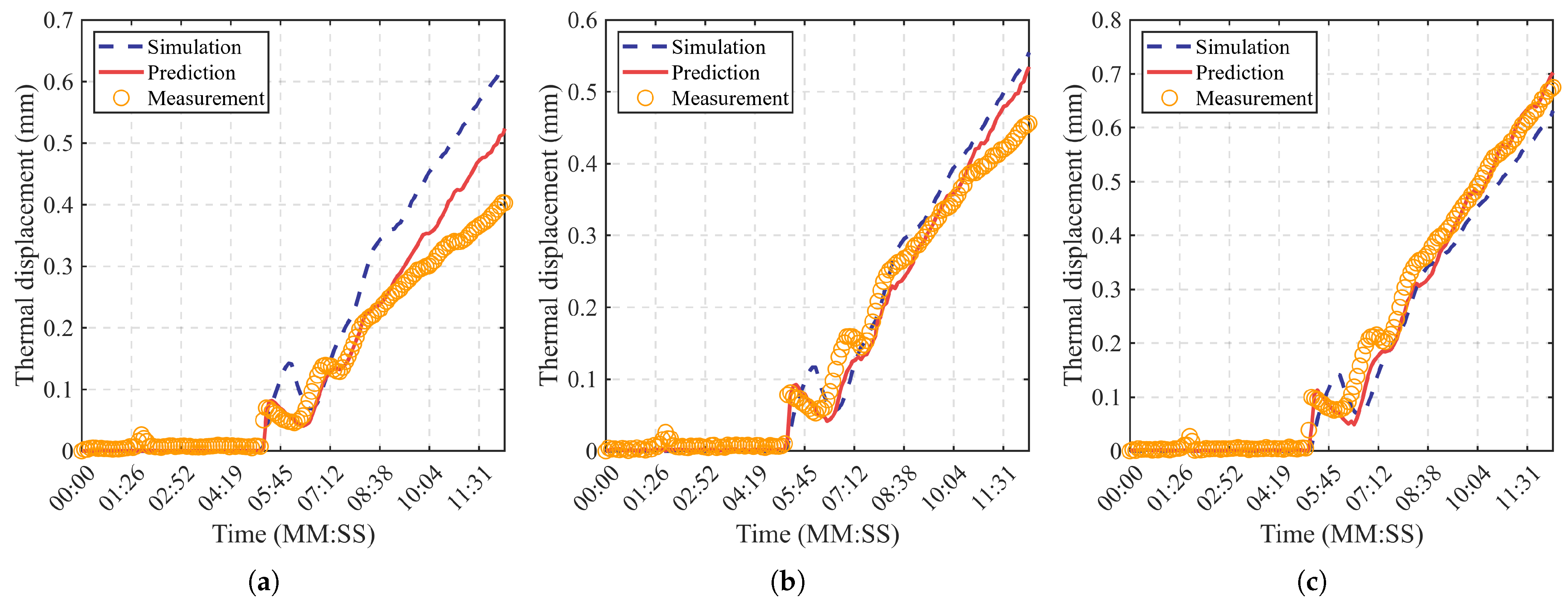
4.1. Comparison A
4.2. Comparison B
4.3. Comparison C
5. Conclusions
Author Contributions
Funding
Data Availability Statement
Conflicts of Interest
Abbreviations
| FEM | Finite element method |
| DOFs | Degrees of freedom |
| CTE | Coefficient of thermal expansion |
| KP(s) | Key point(s) |
| TFR | Temperature field reconstruction |
| SDF | Solving thermal deformation fields |
| ATCS | Active temperature control system |
| PC | Personal computer |
| MaAE | Maximum absolute error |
| MAE | Mean absolute error |
| RMSE | Root-mean-square error |
References
- Rai, A.; Robinson, J.A.; Tate-Brown, J.; Buckley, N.; Zell, M.; Tasaki, K.; Karabadzhak, G.; Sorokin, I.V.; Pignataro, S. Expanded benefits for humanity from the International Space Station. Acta Astronaut. 2016, 126, 463–474. [Google Scholar] [CrossRef]
- Wang, X.; Zhang, Q.; Wang, W. Design and Application Prospect of China’s Tiangong Space Station. Space Sci. Technol. 2023, 3, 35. [Google Scholar] [CrossRef]
- Appel, S.; Wijker, J. Simulation of Thermoelastic Behaviour of Spacecraft Structures: Fundamentals and Recommendations; Springer Aerospace Technology, Springer International Publishing: Cham, Switzerland, 2022. [Google Scholar] [CrossRef]
- Shen, J.; Zeng, X.; Luo, Y.; Cao, C.; Wang, T. Research on Strain Measurements of Core Positions for the Chinese Space Station. Sensors 2018, 18, 1834. [Google Scholar] [CrossRef] [PubMed]
- Maropoulos, P.G.; Muelaner, J.E.; Summers, M.D.; Martin, O.C. A new paradigm in large-scale assembly—research priorities in measurement assisted assembly. Int. J. Adv. Manuf. Technol. 2014, 70, 621–633. [Google Scholar] [CrossRef]
- Guerrero, J.M.; Sasikumar, A.; Llobet, J.; Costa, J. Experimental and virtual testing of a composite-aluminium aircraft wingbox under thermal loading. Aerosp. Sci. Technol. 2023, 138, 108329. [Google Scholar] [CrossRef]
- Saadat, M.; Cretin, L.; Sim, R.; Najafi, F. Deformation analysis of large aerospace components during assembly. Int. J. Adv. Manuf. Technol. 2009, 41, 145–155. [Google Scholar] [CrossRef]
- Garcia-Luis, U.; Gomez-San-Juan, A.M.; Navarro-Medina, F.; Peláez Santos, A.E.; Gonzalez De Chaves Fernandez, P.; Ynigo-Rivera, A.; Aguado-Agelet, F. Evaluation of the thermo-elastic response of space telescopes using uncertainty assessment. Acta Astronaut. 2024, 219, 300–317. [Google Scholar] [CrossRef]
- Yang, L.; Fan, Z.; Wang, K.; Sun, H.; Hu, S.; Zhu, J. Thermal Deformation Measurement of Aerospace Honeycomb Panel Based on Fusion of 3D-Digital Image Correlation and Finite Element Method. Photonics 2023, 10, 217. [Google Scholar] [CrossRef]
- Tang, X.; Chen, D.; Xin, L.; Sun, Z.; Zhao, Z.; Yan, Z.; Tian, X.; Li, X. A DIC method for thermal micro-deformation measurement of satellite high stability composite structure in simulated space environment. Opt. Lasers Eng. 2023, 169, 107722. [Google Scholar] [CrossRef]
- Zhang, L.; Tang, Z.; Chen, M.; Fu, Y.; Li, D.; Ma, K. Impact Analysis of Thermo-mechanical Deformation to the Unlocking Performance of Locking Device for Manipulator on Chinese Space Station. J. Phys. Conf. Ser. 2022, 2403, 012011. [Google Scholar] [CrossRef]
- Cheng, Y.; Jin, S.; Qiao, K.; Zhou, S.; Xue, J. Thermal displacement prediction of high-speed electric spindles based on BWO-BiLSTM. Precis. Eng. 2024, 89, 438–450. [Google Scholar] [CrossRef]
- Zhang, G.; Chen, X.; Yang, D.; Wang, L.; He, X.; Zhang, Z. Multi-physics coupling simulation technique for phase stable cables. Electronics 2023, 12, 1602. [Google Scholar] [CrossRef]
- Zhang, Y.; Zeng, X.; Feng, J.; Gao, D.; Hao, W.; Li, B.; Li, K. Cathode Thermal Experiment Improves Performance of Magnetron Injection Gun for 170 GHz Gyrotron. Electronics 2025, 14, 346. [Google Scholar] [CrossRef]
- Zhang, H.; Zhao, X.; Mei, Q.; Wang, Y.; Song, S.; Yu, F. On-orbit thermal deformation prediction for a high-resolution satellite camera. Appl. Therm. Eng. 2021, 195, 117152. [Google Scholar] [CrossRef]
- Wang, L.; Deng, L.; Tang, C.; Fan, Q.; Wang, C.; Che, D. Thermal deformation prediction based on the temperature distribution of the rotor in rotary air-preheater. Appl. Therm. Eng. 2015, 90, 478–488. [Google Scholar] [CrossRef]
- Ledermann, C.; Hanske, C.; Wenzel, J.; Ermanni, P.; Kelm, R. Associative parametric CAE methods in the aircraft pre-design. Aerosp. Sci. Technol. 2005, 9, 641–651. [Google Scholar] [CrossRef]
- Yang, B.; Ross-Pinnock, D.; Muelaner, J.; Mullineux, G. Thermal compensation for large volume metrology and structures. Int. J. Metrol. Qual. Eng. 2017, 8, 21. [Google Scholar] [CrossRef]
- Barber, J.R. Elasticity; Vol. 172, Solid Mechanics and Its Applications; Springer: Dordrecht, The Netherlands, 2010. [Google Scholar] [CrossRef]
- Kleijnen, J.P. Kriging metamodeling in simulation: A review. Eur. J. Oper. Res. 2009, 192, 707–716. [Google Scholar] [CrossRef]
- Ulaganathan, S.; Couckuyt, I.; Deschrijver, D.; Laermans, E.; Dhaene, T. A Matlab Toolbox for Kriging Metamodelling. Procedia Comput. Sci. 2015, 51, 2708–2713. [Google Scholar] [CrossRef]
- Sacks, J.; Welch, W.J.; Mitchell, T.J.; Wynn, H.P. Design and Analysis of Computer Experiments. Stat. Sci. 1989, 4, 409–423. [Google Scholar] [CrossRef]
- Hetnarski Richard, B.; Eslami, M.R. Basic Laws of Thermoelasticity. In Thermal Stresses—Advanced Theory and Applications; Springer International Publishing: Cham, Switzerland, 2019; pp. 1–43. [Google Scholar] [CrossRef]


| Key Point | Corresponding Node | Nodal Coordinates |
|---|---|---|
| 1 | 259 | (0, 760.000, −112.500) |
| 2 | 3123 | (−102.127, 743.014, −145.000) |
| 3 | 2257 | (174.839, 729.336, −227.500) |
| Field | t1 | t2 | t3 | t4 | t5 | t6 | t7 | t8 | t9 | t10 | Avg. |
|---|---|---|---|---|---|---|---|---|---|---|---|
| 0.035 | 0.031 | 0.031 | 0.048 | 0.036 | 0.035 | 0.032 | 0.031 | 0.042 | 0.029 | 0.035 | |
| 0.044 | 0.035 | 0.041 | 0.033 | 0.033 | 0.031 | 0.032 | 0.031 | 0.032 | 0.031 | 0.035 |
| Trail | ||||||
|---|---|---|---|---|---|---|
| Total | TFR | SFD | Total | TFR | SFD | |
| 1 | 0.137 | 0.030 | 0.052 | 0.154 | 0.034 | 0.059 |
| 2 | 0.137 | 0.029 | 0.052 | 0.139 | 0.037 | 0.052 |
| 3 | 0.135 | 0.029 | 0.049 | 0.136 | 0.036 | 0.051 |
| 4 | 0.141 | 0.029 | 0.052 | 0.137 | 0.032 | 0.050 |
| 5 | 0.134 | 0.031 | 0.048 | 0.135 | 0.036 | 0.049 |
| 6 | 0.136 | 0.033 | 0.051 | 0.134 | 0.033 | 0.049 |
| 7 | 0.136 | 0.029 | 0.050 | 0.136 | 0.032 | 0.051 |
| 8 | 0.140 | 0.031 | 0.051 | 0.145 | 0.031 | 0.048 |
| 9 | 0.138 | 0.046 | 0.049 | 0.134 | 0.049 | 0.049 |
| 10 | 0.138 | 0.029 | 0.053 | 0.134 | 0.033 | 0.049 |
| Key Point | MaAE | MAE | RMSE | |||
|---|---|---|---|---|---|---|
| Simulation | Prediction | Simulation | Prediction | Simulation | Prediction | |
| 1 | 0.228 | 0.121 | 0.065 | 0.026 | 0.095 | 0.042 |
| 2 | 0.098 | 0.078 | 0.027 | 0.018 | 0.037 | 0.026 |
| 3 | 0.122 | 0.081 | 0.026 | 0.017 | 0.037 | 0.025 |
Disclaimer/Publisher’s Note: The statements, opinions and data contained in all publications are solely those of the individual author(s) and contributor(s) and not of MDPI and/or the editor(s). MDPI and/or the editor(s) disclaim responsibility for any injury to people or property resulting from any ideas, methods, instructions or products referred to in the content. |
© 2025 by the authors. Licensee MDPI, Basel, Switzerland. This article is an open access article distributed under the terms and conditions of the Creative Commons Attribution (CC BY) license (https://creativecommons.org/licenses/by/4.0/).
Share and Cite
Li, J.; Zhao, C.; Lu, Y.; Su, Y.; Zhang, Y.; Liu, W. Online Sensing of Thermal Deformation in Complex Space Bulkheads Driven by Temperature Field Measurements. Electronics 2025, 14, 2405. https://doi.org/10.3390/electronics14122405
Li J, Zhao C, Lu Y, Su Y, Zhang Y, Liu W. Online Sensing of Thermal Deformation in Complex Space Bulkheads Driven by Temperature Field Measurements. Electronics. 2025; 14(12):2405. https://doi.org/10.3390/electronics14122405
Chicago/Turabian StyleLi, Junqing, Changxi Zhao, Yongkang Lu, Yipin Su, Yang Zhang, and Wei Liu. 2025. "Online Sensing of Thermal Deformation in Complex Space Bulkheads Driven by Temperature Field Measurements" Electronics 14, no. 12: 2405. https://doi.org/10.3390/electronics14122405
APA StyleLi, J., Zhao, C., Lu, Y., Su, Y., Zhang, Y., & Liu, W. (2025). Online Sensing of Thermal Deformation in Complex Space Bulkheads Driven by Temperature Field Measurements. Electronics, 14(12), 2405. https://doi.org/10.3390/electronics14122405