1. Introduction
As the core power unit of industrial production systems, induction motors occupy an important position in the global manufacturing industry. However, electromagnetic vibration noise of motors caused by eccentricity and of other origins is a very common occurrence. In the magnetic field of the motor, all parts of the motor undergo different degrees of deformation due to electromagnetic forces, and the amount of deformation varies with time, which leads to macroscopic electromagnetic vibration. Reference [
1] demonstrates a methodology for vibration analysis of typical mechanical and electromagnetic problems in the field of vibration motor diagnostics. Reference [
2] reveals the effect of voltage interharmonics on cage induction motors, where simple harmonics may lead to torque pulsations and cause torque resonance. The findings of interharmonic malpractice in seven motors rated at 3 kW–5.6 MW are presented.
An effective way to reduce electromagnetic vibration in induction motors is to use a skewed rotor. Early studies on skewed rotors focused on the weakening effect of rotor skew parameters on the harmonic air gap magnetic field, and the variation of the air gap magnetic field when the rotor is skewed was determined by using analytical and finite element methods [
3,
4]. According to the analysis of the air gap magnetic field in the references [
5,
6,
7], when the rotor deflection distance is small, the effect on the fundamental magnetic field of the motor is small, but the effect on the harmonic magnetic field is large, especially on the magnetic torque and the permeability tooth harmonics. Reference [
8] gives an expression for the saturation factor of the leakage reactance when the rotor of an induction motor is skewed, and [
9] shows by a two-dimensional time-stepping finite element method that rotor skewing significantly attenuates the toothed harmonic component of the induced counter electromotive force.
Reference [
10] analyzed different skew angles of switched reluctance motor rotor and their effects on key electromagnetic parameters, which resulted in a 56.2% reduction in radial force at 5% skew angle. References [
11,
12] reduced the cogging torque by changing the rotor structure of electric vehicle motors, such as skewed pole splitting of the rotor and applying wedge-shaped skewing. Reference [
13] investigated and analyzed the torque pulsation of a servomotor by changing the rotor topology and reduced the torque pulsation, which was 3.75%, to about 2.08%.
Due to the difficulty of process manufacturing, the motor rotor cannot be tilted by too large a number of degrees, and as the rotor oblique groove inclination can only be within a certain range to reduce the tooth oblique wave content, so [
14,
15] analyzed the double oblique rotor on the vibration and noise effects. Double-sloping and a new type of sloping slot can make the rotor sloping slot inclination angle larger, so as to reduce the vibration and noise of the motor more effectively.
Practical and theoretical analyses show that for different types of motors, such as small and medium-sized induction motors, permanent magnet synchronous motors, and switched reluctance motors, choosing the appropriate rotor slant slot angle can also effectively reduce vibration and noise [
16,
17,
18,
19,
20].
Previously, scholars analyzed the damping effect of sloping slots on motor vibration by analyzing the weakening effect of different types of motors using different rotor sloping slots on harmonics. The advantage of this method is that it is more convenient to analyze the harmonics and torque pulsations that generate force waves, but the effect of the skew slot on the electromagnetic excitation force cannot be obtained. In this paper, the skew coefficient of the rotor is investigated, and the degree of weakening of the electromagnetic excitation force is directly analyzed by the skew coefficient, taking a 7.5 kW motor as an example. In this way, the optimum angle of the skew slot was found to reduce the electromagnetic vibration of the motor. The optimum angle for reducing the electromagnetic vibration of the motor was found, and the validity of the theoretical simulation verified by the electromagnetic–mechanical excitation separation test bench for rotors with tilt angles of 10°, 12.8°, 14°, and 20°, respectively. The skew coefficient can be substituted into different rotor types of induction motors for analysis. The stages of this study and evaluation are detailed in the following sections.
2. Skew Factor
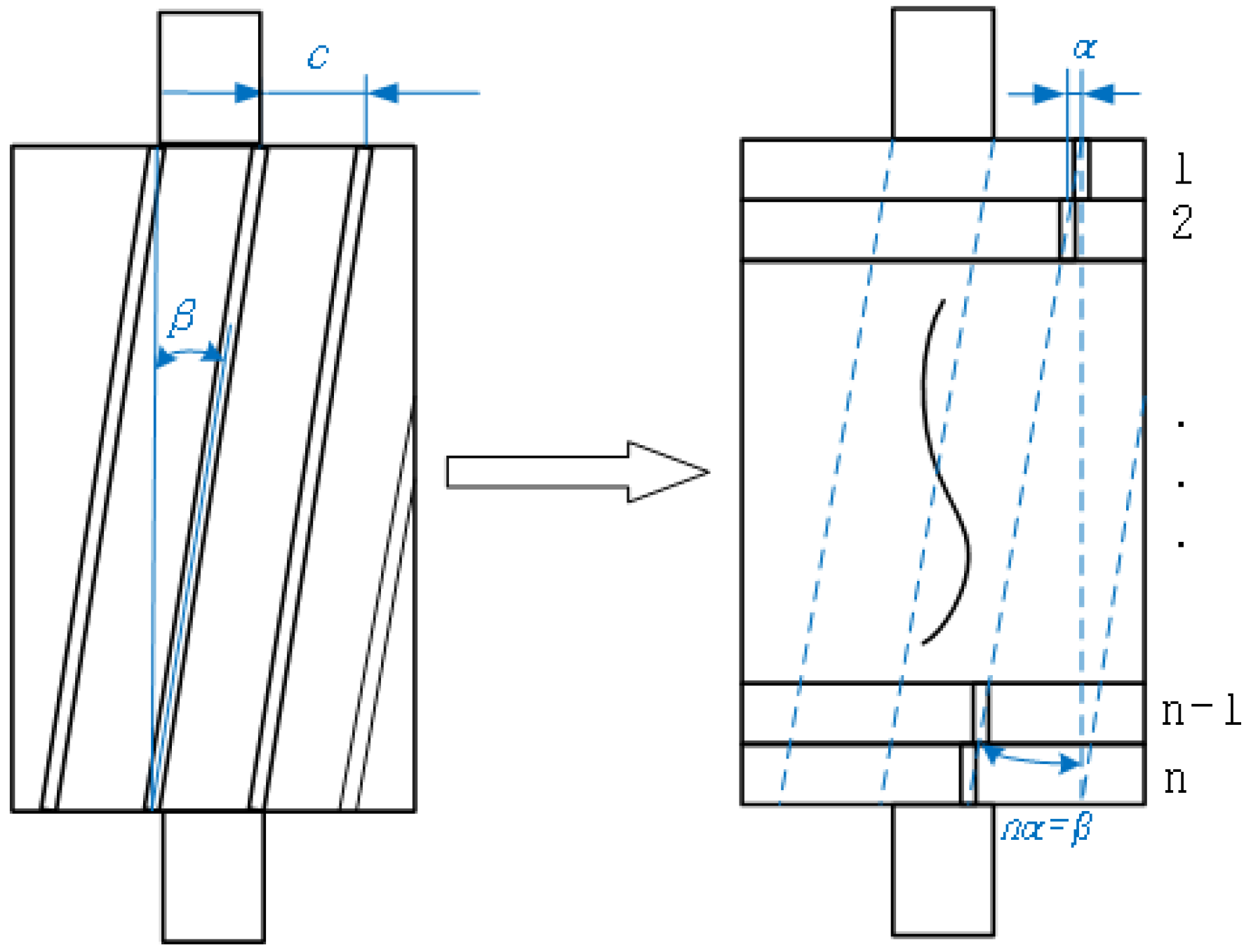
A single-slewed rotor refers to a rotor conductor that is offset by a certain angle in the axial direction, which causes both the fundamental and harmonics of the stator to be weakened. In order to calculate the weakening effect, a skewed coefficient needs to be added in addition to the potential distribution coefficient and pitch coefficient.
Figure 1 shows a simplified schematic diagram of a single skewed rotor. In the rotor structure of induction motors, the role of the end rings is more significant during motor starting or speed change. The theoretical model of this study focuses on the analysis of electromagnetic vibration under steady state operation (slip rate s < 2%), where the rotor current frequency is very low, the resistance of the end rings dominates the impedance characteristics, and the regulation of the magnetic field distribution in the air gap is negligible. Thus the end ring portion of an ordinary aluminum rotor is omitted from the figure.
The main parameters of the motor used in this paper are shown in the following
Table 1 [
21]:
The skew factor is calculated from the skew angle β where α is the small angular difference between neighboring guide bars and c is the spacing between two neighboring guide bars. The physical model shown in
Figure 1 can be regarded as an infinite series of infinitesimal segments (
n→∞), with each segment angular displacement being dθ and satisfying β = ∫dθ. In the discrete model, if the number of segments is
n, the angle of each segment α = β/
n, which strictly satisfies nα = β when
n→∞, where β is the entire conductor skew section of the radian, i.e., skewness.
Using the synthesis method of electric potential in distributed conductors, the skewing factor of the fundamental wave can be obtained [
8,
22], as seen in Equation (1):
where λ is the rotor skewed number of stator slots.
For the convenience of calculation, the number of skew stator slots is used to represent, then proceeding as follows:
where
D is the stator inner diameter,
S1 is the number of stator slots,
τ is the pitch.
For the skew factor of the
vth harmonic,
β is replace in the above formula with
υβ, so the skew factor for the
vth harmonic is the following:
where
bskv is the rotor skew factor for the
vth harmonic wave.
Therefore, to eliminate the
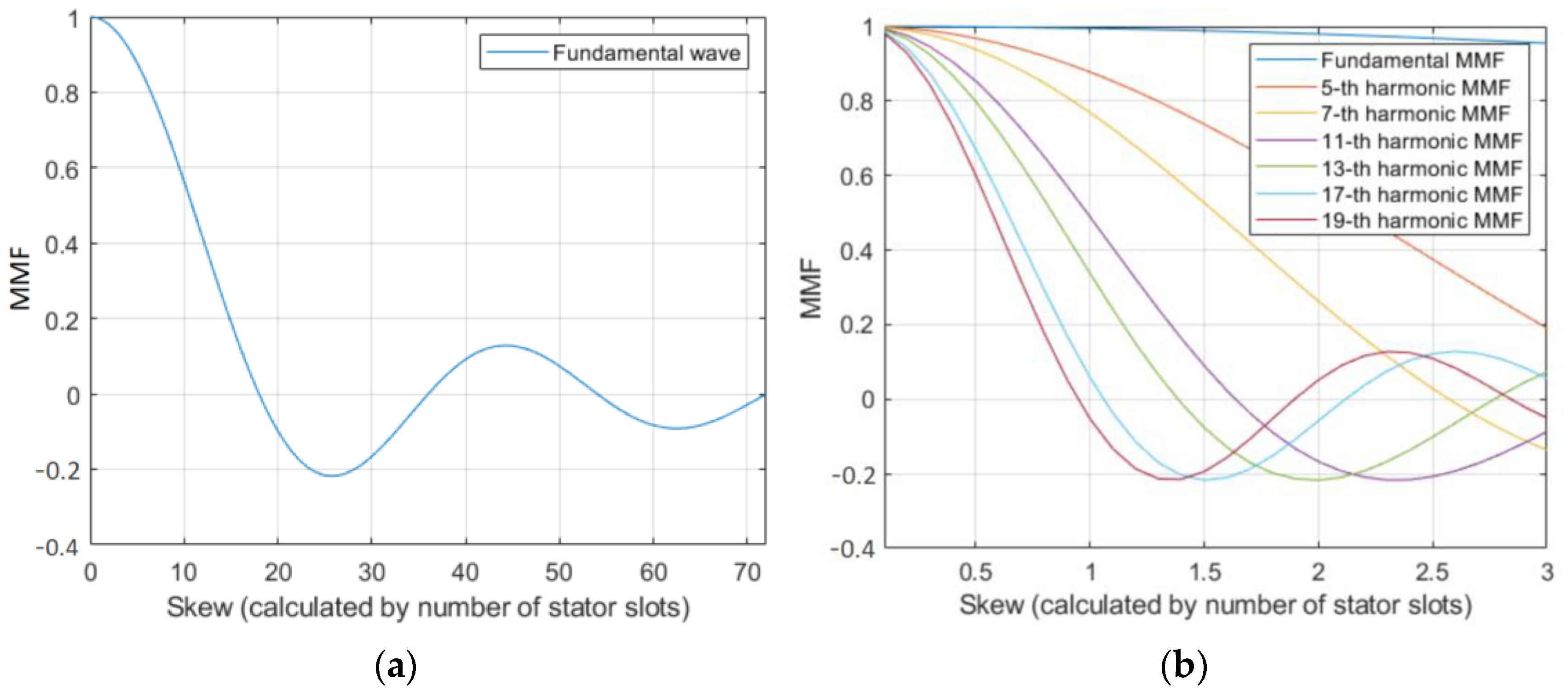
vth harmonic, it is only necessary to make the skew factor of this harmonic equal to zero, but since harmonics of different orders exist simultaneously, it is necessary to consider them in a comprehensive way and to adopt an appropriate skew distance for processing. Based on the skew coefficients of the fundamental and harmonics, the relationship between the skew distance and the magnetomotive force (MMF) coefficients of each order is shown in
Figure 2.
As shown in
Figure 2, the fundamental or harmonic coefficients can reach bskv = 0 when the rotor skew angle is at certain specific values. Since the fundamental wave is the main component that generates the torque output in the motor, the skew distance should be minimized to ensure that the fundamental coefficient is large enough. However, in order to reduce the content of the harmonic waves, the skew distance should be selected at the position where the harmonic wave coefficient is 0 as much as possible. At the same time, as shown in the figure, when the skew distance is 1 or 2 stator teeth, the fundamental wave coefficients are bsk1 = 0.9949 and bsk1 = 0.9798, respectively, and the coefficients of the 17th and 19th harmonics are bsk17 = 0.0585, bsk19 = 0.05236, bsk17 = 0.05764, and bsk19 = 0.0515, respectively. The amplitude of the tooth harmonics decreases significantly. The coefficients of the 11th and 13th harmonics change from bsk11 = 0.4895 and bsk13 = 0.3316 to bsk11 = −0.1674 and bsk13 = −0.217, respectively. Therefore, when only the 17th and 19th harmonics weakening is considered, the skew angle can be selected as 1 stator slot distance, and when the 11th and 13th harmonics weakening is considered, 2 stator slot distances are more optimal. When the skew angle is selected between 1.3 and 1.5 stator slot distance, the fundamental coefficient is bsk1 = 0.99, and it has a good effect on the weakening of the 13th harmonic coefficient approaching 0.
3. Radial Force Wave with Skewed Rotor
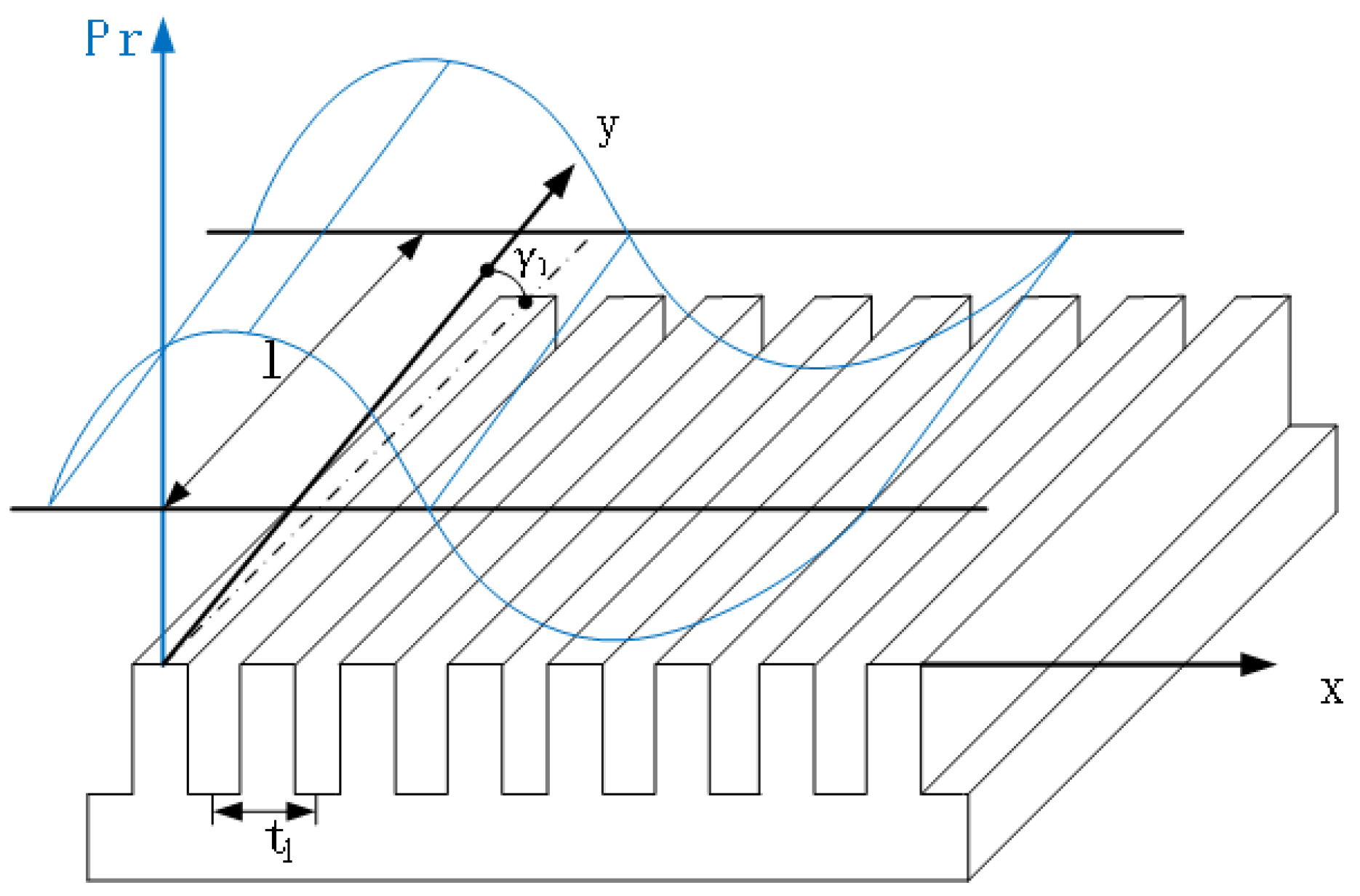
After analyzing the skew factor, the radial force wave of the rotor skew is analyzed, and
Figure 3 gives the spatial model of the rotor skew.
The stator harmonic magnetic field can be expressed as follows:
where
Bμ is the magnitude of the
μ stator harmonic magnetic field and
μ is the number of stator harmonics.
The harmonic magnetic field generated by the rotor fundamental current is the following:
where
Bv is the magnitude of the
v rotor harmonic magnetic field and
v is the number of rotor harmonics.
The above formulas of Equations (4) and (5) obtain the radial electromagnetic force wave generated by the interaction of the two magnetic fields as below:
in the formula
,
,
,
,
where
Pr is the
rth order force wave amplitude, φ
0r, φ
μz, φ
vz are the phase angles of the different harmonic magnetic fields, ω
1, ω
v are the angular velocities of different harmonic magnetic fields.
It can be seen from Equation (3) that the distribution amplitude of the radial force wave varies in the axial direction due to the rotor being skewed.
To further analyze the influence of the oblique slot on the 0-order axial vibration, the average radial electromagnetic excitation force is obtained by integrating the longitudinal direction of the iron core as follows:
The expression for is .
It can be seen that
Kskv agrees formally with the skew coefficient in Equation (1), so
Kskv is the skew coefficient described above. Therefore, when the slot is tilted, each order of the magnetomotive force acting on the stator and the skew coefficient also satisfies the relationship equation shown in
Figure 2.
4. Electromagnetic Excitation Force Under Tooth Skew
To further analyze the effect of skew on vibration, it is necessary to analyze the electromagnetic excitation force on the tooth. Since the force wave derived in the previous section cannot be directly extended to a three-dimensional plane, the stator iron core must be extended along the circumferential direction. Therefore, the analysis is carried out in the Cartesian coordinate system. The Y direction is the motor rotation axis, i.e., the longitudinal coordinate of the iron core, and the X direction is the tangential coordinate of the circumferential direction along the expanded plane of the stator. γ
1 is the axial inclination angle of the stator slot, t
1 is the tooth pitch on the surface of the inner hole of the stator and l is the effective length of the core. The spatial calculation model of the motor stator for the force wave acting on the tooth is shown in
Figure 4.
The force density of the radial force wave skewed along the inner hole of the stator and the rotation axis is given by the following formula:
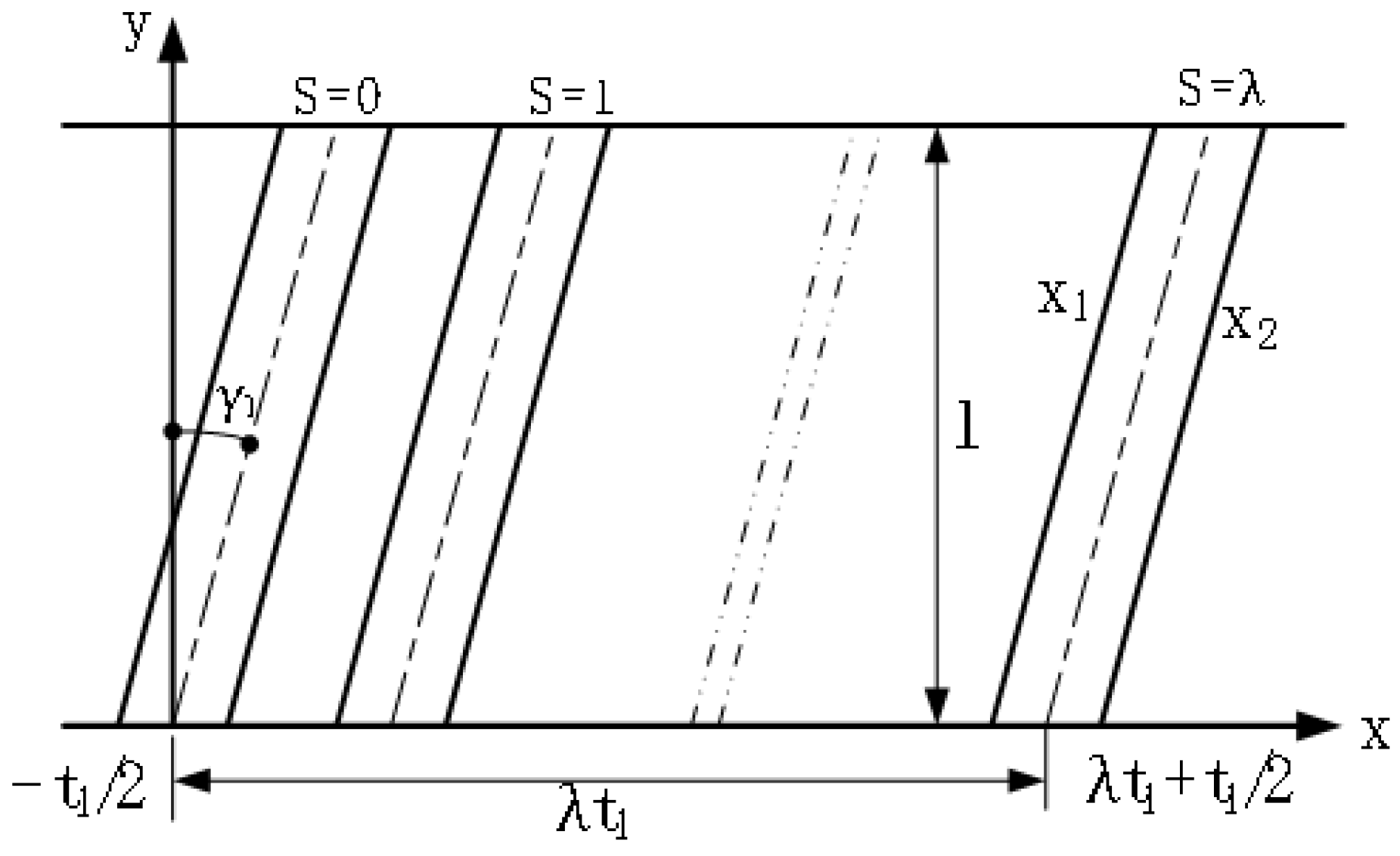
In order to calculate the electromagnetic excitation force on the stator side-teeth, the inclination of the cogging slot in
Figure 4 is projected onto the XOY plane, and
Figure 5 shows the schematic diagram of the projection, and the relationship between the various parameters can be obtained. The number of stator teeth is from S = 0 to S = λ, where S
1 is the number of stator teeth, γ
1 is the axial inclination angle of the stator slot, which is determined by the inclination distance and the iron core length, which is tanγ
1 = bck
1/l. Among them, bck
1 is the arc length of the skewed slot distance, and t
1 is the tooth pitch on the surface of the inner hole of the stator, which is t = πD/S1; x
1 = ytanγ
1 + λt
1−t
1/2, x
1 = ytanγ
1 + λt
1 + t
1/2, λ is the number of the tooth.
The excitation force acting on the rigid teeth can be determined by integrating the force wave density along a certain stator pitch surface. The force uniformly distributed along the tooth section of No. λ is transmitted to the tooth root according to the force wave expressed by Equation (9):
After rearranging the above formula, we obtain the following equation:
where
ξr is the vibration amplitude coefficient,
ξzck is the slant factor, and
l is the rotor axial length.
Although the above equations are obtained by tilting the stator teeth, the essence of both stator tooth tilting and rotor slant slotting is to introduce a spatial phase difference through axial geometric offsets that attenuate a specific number of magnetic field harmonics. The form of the phase difference equation is identical for both, with only the parameters replaced with rotor-related values. Therefore, the same applies to the case of rotor slant slots. It can be seen from Equation (7) that the coefficient of the excitation force transmitted by the electromagnetic force wave through the teeth is similar to the coefficient of the skewed, which is a function continuously oscillating through the zero point.
After optimizing the parameters of the skew, when the excitation force transmitted to the teeth is zero, the appropriate skewed slot distance is obtained. The skew slot distance can be calculated using the following formula:
In, k = 1, 2, 3, … where bck is the distance the rotor is skewed in the circumferential direction.
According to Equation (14), there are two parts to consider when considering the rotor slot. If the distance of the rotor slant slot is larger, a larger reduction of the magnetic moment wave will be produced, as shown in
Figure 2, which will affect the performance of the motor. Due to the limitations of motor processing and manufacturing techniques, it is difficult to produce a large, skewed angle in the iron core of small and medium-sized motors. Even if it can be produced, there are many defects. Therefore, the maximum slant slot distance of five stator slots is selected in the simulation.
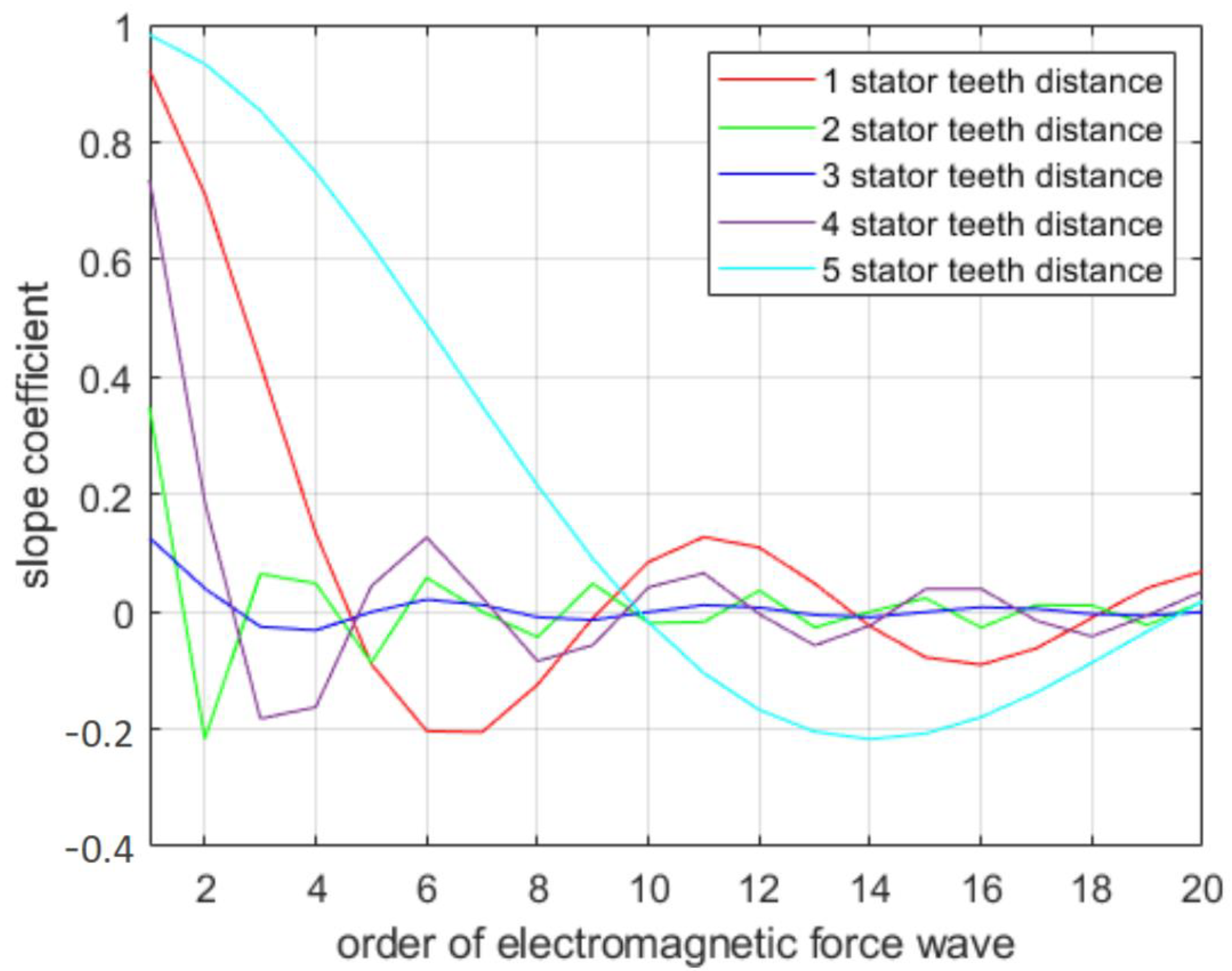
Figure 6 shows the variation of the slope coefficient for a 36–28 motor rotor with skew slot spacing from 1–5 stator teeth distance. The slope coefficient directly reflects the change in amplitude of the electromagnetic excitation force, and from this coefficient, it can be seen that when the rotor is tilted at a certain angle, the higher-order electromagnetic forces are slightly weakened. At the same time, when the tilt angle is greater than one stator tooth, only specific electromagnetic forces higher than a certain order are weakened to within 15%. When the pitch angle is three stator teeth apart, it is optimal, with each order of force being weakened by an average of approximately 5%.
After obtaining the rotor skew coefficient for induction motors with different parameters, the relationship between electromagnetic excitation force and skew coefficient can be obtained by Equation (7). Thus, the optimized skew slot parameters to reduce the electromagnetic excitation force are calculated, and the rotor tilt distance in the circumferential direction can be obtained by combining with Equation (14).
5. Experiment
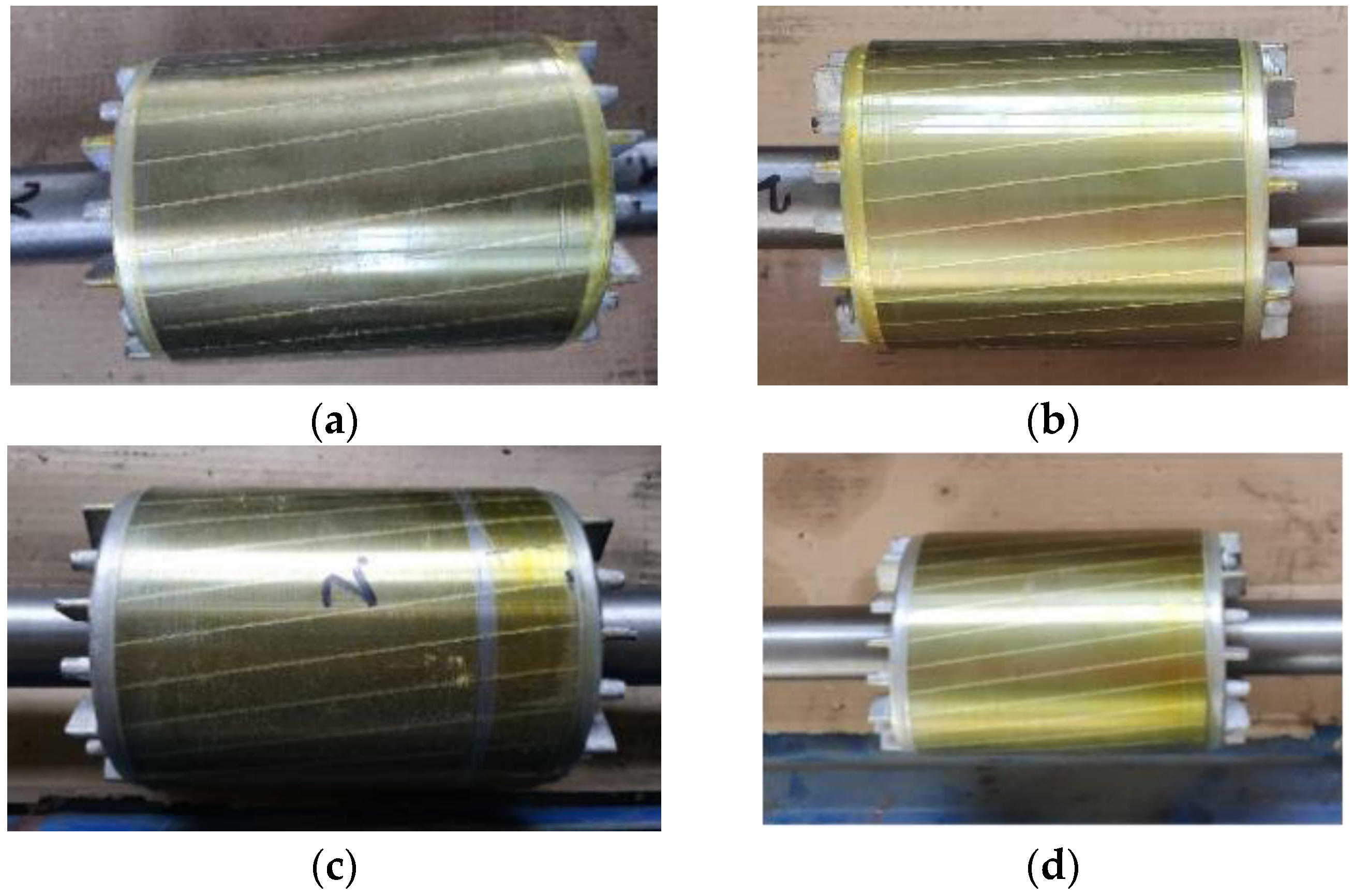
Vibration tests were performed for rotors with skew angles of 0°, 10°, 12.8°, 14°, and 20°. The rotor with 0° skew is a straight skewed rotor and is given in the literature [
21].
Figure 7 shows the plots for rotors with other parameters.
As the skewed rotor reduces the torque performance of the induction motor, the torque performance of the skewed rotor was tested with different parameters. The maximum torque and the locked rotor torque of the motor for different rotors were tested. The test equipment is shown in
Figure 8.
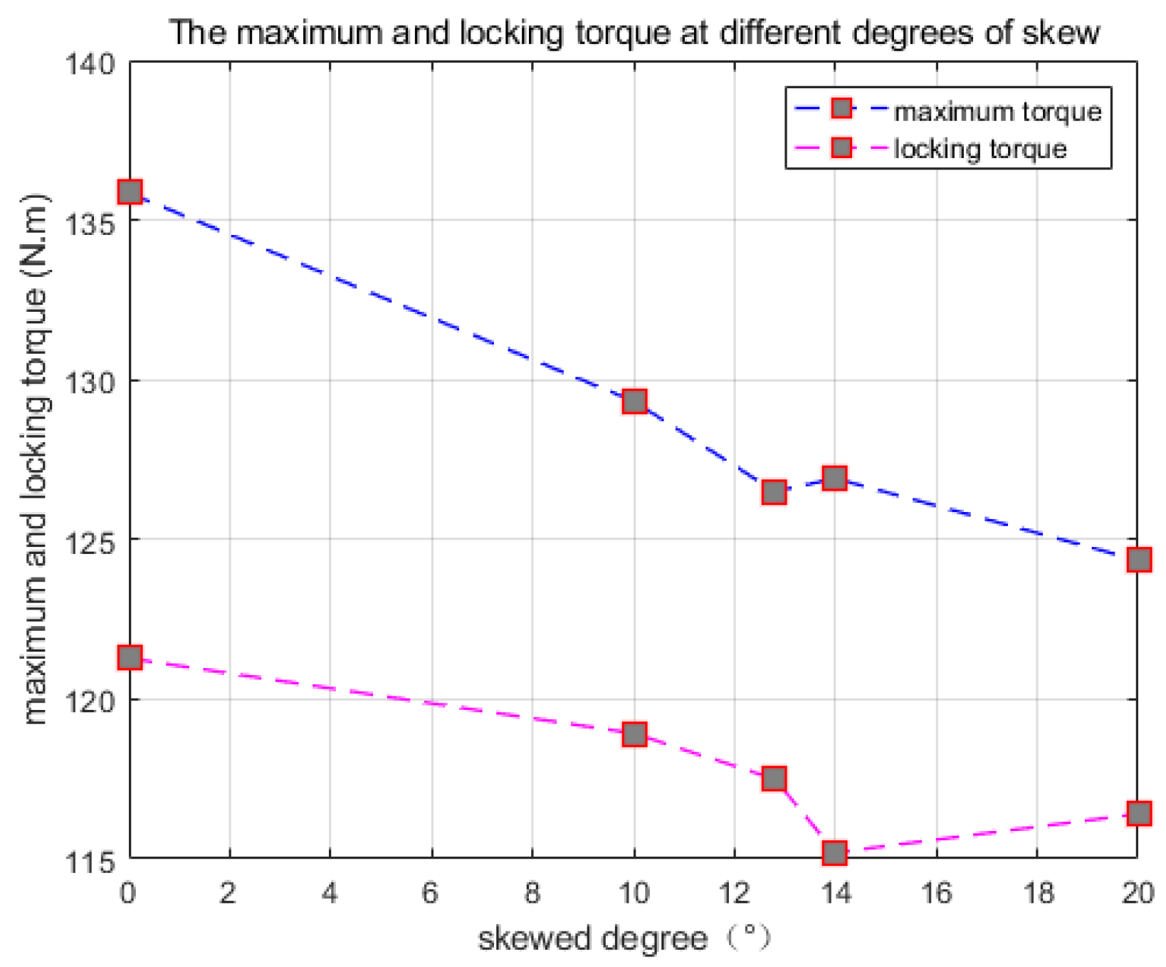
The test results for straight slot rotors and different skewed parameter slot rotors are shown in
Figure 9. The comparison of maximum torque and stall torque in the figure shows that the actual data trend of the decrease in skewed slot torque is basically consistent with the results of the simulation analysis in the previous text. The reason why the torque at a rotor skewed slot angle of 12.8° is smaller than that at 14° is mainly due to the fact that the skewed slot parameters of these two rotors are similar—the manufacturer ensures the skewed slot parameters through molds, so there is some error, but the overall trend has not changed. If the skewed slot distance increases, it will lead to a decrease in the starting and overload capability of the motor. Therefore, before adopting the skewed slot method to reduce vibration, it is necessary to consider whether the change in maximum torque can meet the performance requirements of the motor.
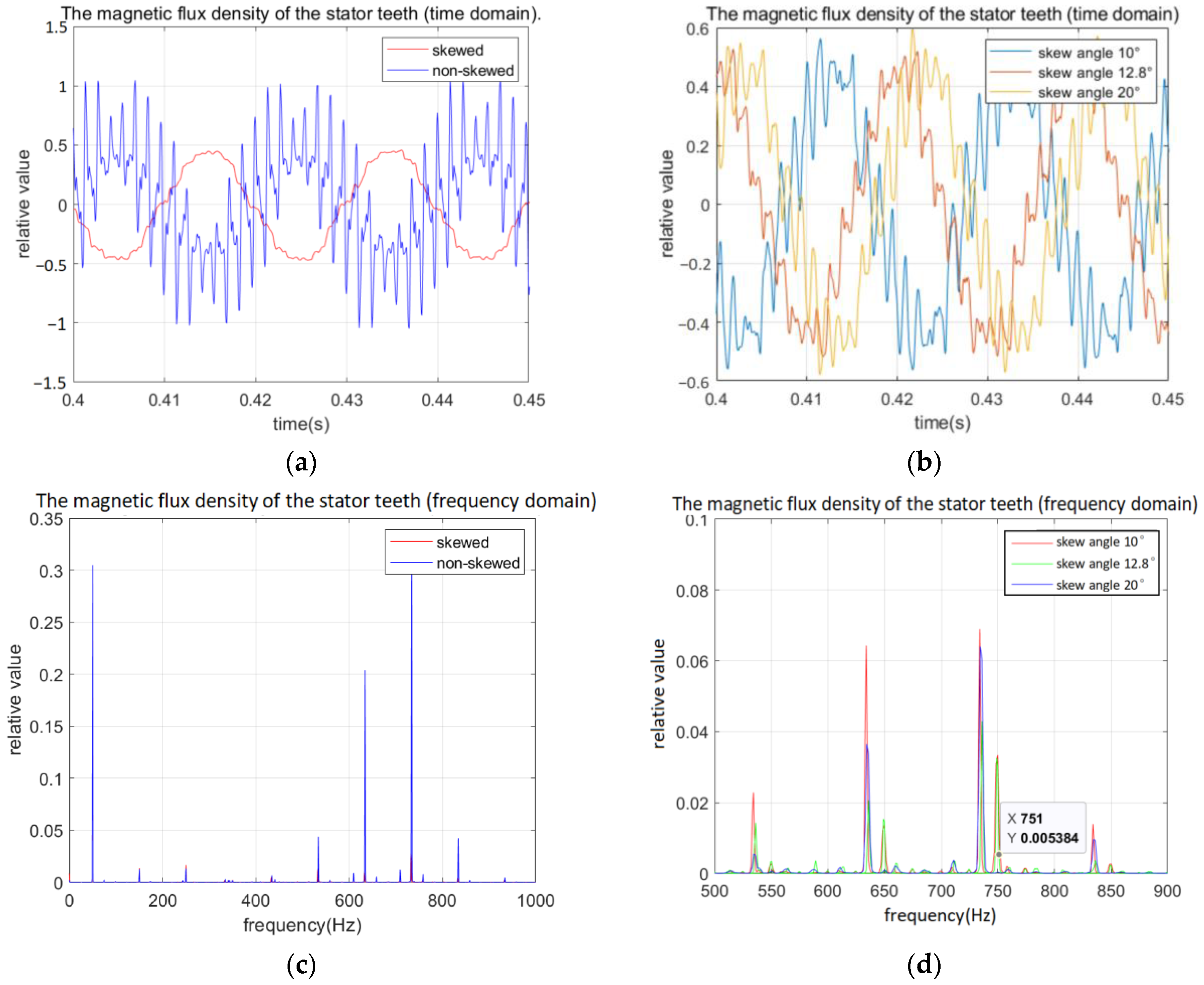
In order to compare better the reduction of tooth harmonics by straight slot and skewed rotors, the air gap magnetic density data are analyzed to further obtain the variation law of the magnetic density, as shown in
Figure 10.
From the comparison of the time-domain data of the air gap magnetic flux density of the straight groove rotor and the chute rotor, it can be seen that the air gap magnetic flux density waveform of the straight groove rotor contains more harmonics in the no-load state, while the air gap magnetic flux density of the chute rotor contains fewer harmonics, and the harmonic content in the gap magnetic flux density waveform is significantly reduced. Through the comparison of Fourier transform in the frequency domain, it can be seen that the amplitude of the harmonic component of the tooth is weakened due to the skew. Under no-load conditions, the time-domain waveform of the air gap flux density contains more harmonics. After the Fourier transform, comparing the harmonic amplitude of the tooth with different deflection grooves, it can be seen that the amplitude of the tooth harmonics does not decrease with the increase of the deflection groove, but changes with the change of the deflection groove coefficient. This is consistent with the results of the skew coefficient analysis.
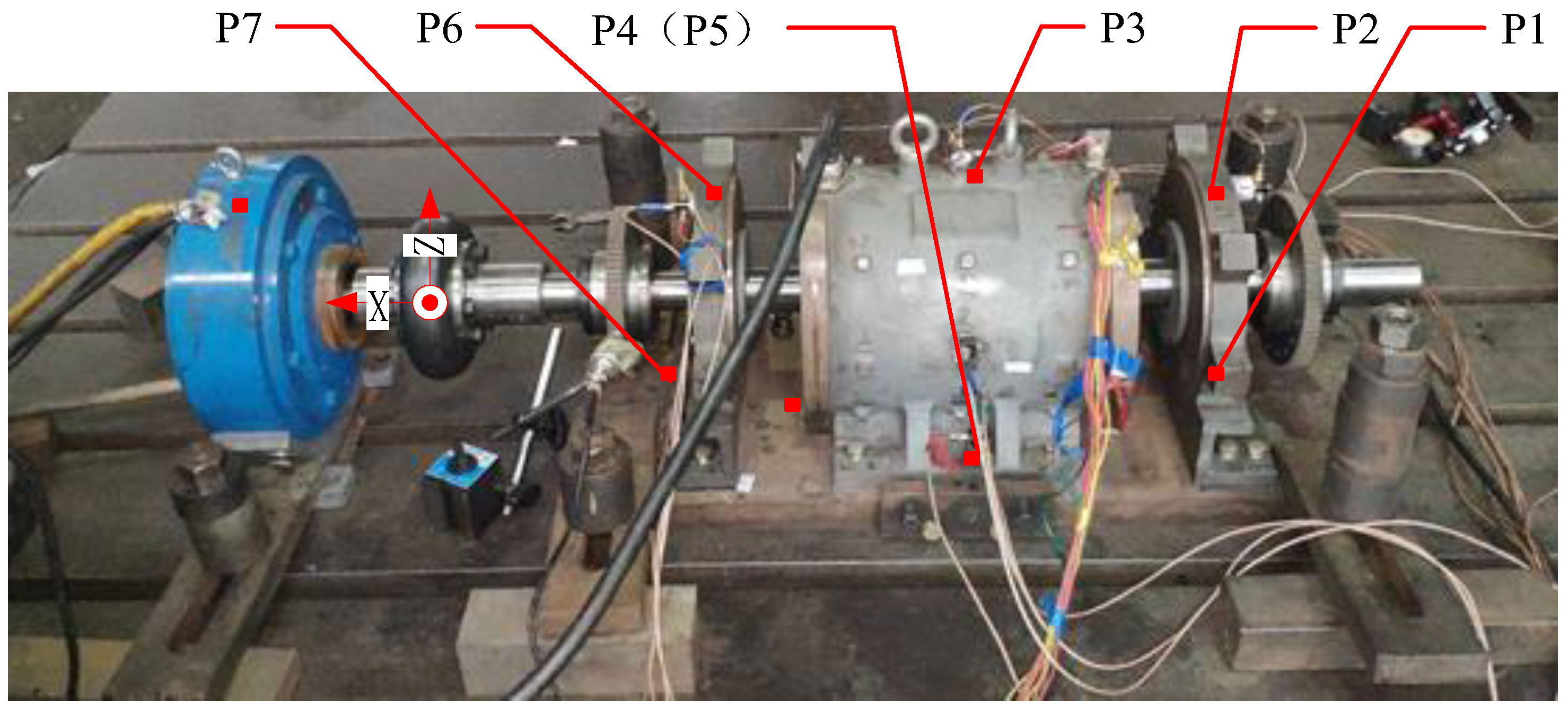
In order to verify the damping effect of the skewed rotor on vibration, vibration tests were carried out on rotors with different skewed rotors on an electromagnetic–mechanical excitation separation test rig. The specific structure of the test rig is shown in
Figure 11, and its detailed parameters can be found in [
21].
In the diagram, X, Y, and Z represent the axial, circumferential radial, and tangential directions of the motor, respectively. Vibration acceleration sensors are installed at points P1 to P7, which are located at the bottom of the non-shaft end cover, the top of the non-shaft end cover, the top of the stator, the stator foot (front and back), the base plate, the top of the shaft end cover, and the bottom of the shaft end cover, in order.
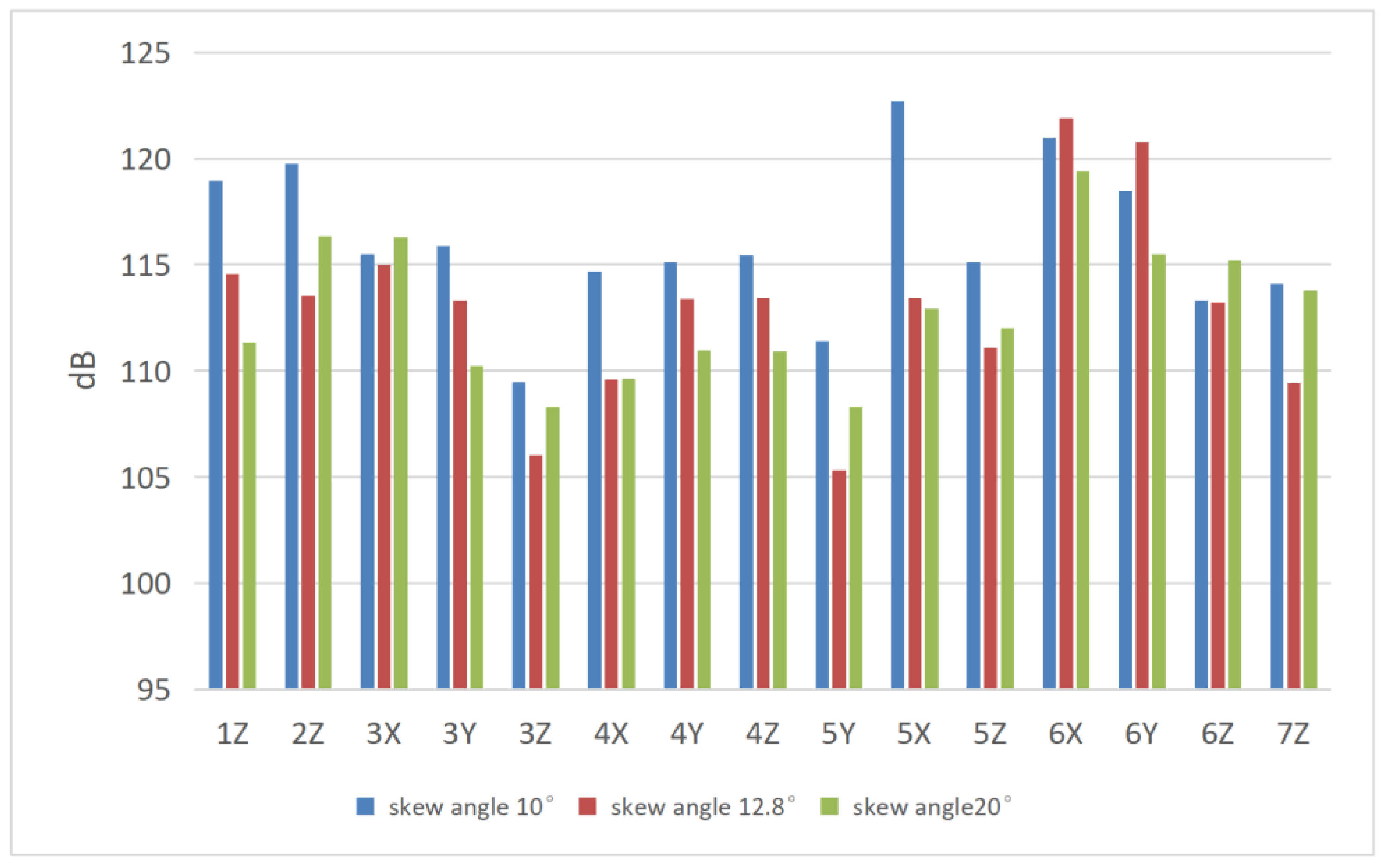
Taking the test results of three different rotors with different inclined slots together, we can observe the overall electromagnetic vibration amplitude and the trend of the different measurement points in three directions. Meanwhile, as can be seen from the amplitude comparison in
Figure 12, the overall amplitude of the casing decreases significantly when the rotor is tilted. The damping effect on the electromagnetic vibration of the stator top and stator foot is the largest, when the tilt is 12.8°; the vibration amplitude in the radial direction of the stator top is 106 dB, and the vibration amplitude of the stator foot is 105.3 dB.
From the vibration data of the sensor on the motor casing in
Figure 13, it can be seen that the electromagnetic vibration of the motor in the transverse and longitudinal directions (i.e., the radial and tangential directions in the circumferential direction) decreases with the increase in the degree of skew, which is consistent with the results of the previous analysis of the skew factor on the force and vibration amplitude of the motor teeth. The axial direction increases with the increase in the degree of skew. This is because in the case of a single skewed, since the skewed will generate an axial force in the axial direction with the increase of the skewed degree, the proportion of the axial force increases, and the vibration increases accordingly. This is without comparing the axial vibration.
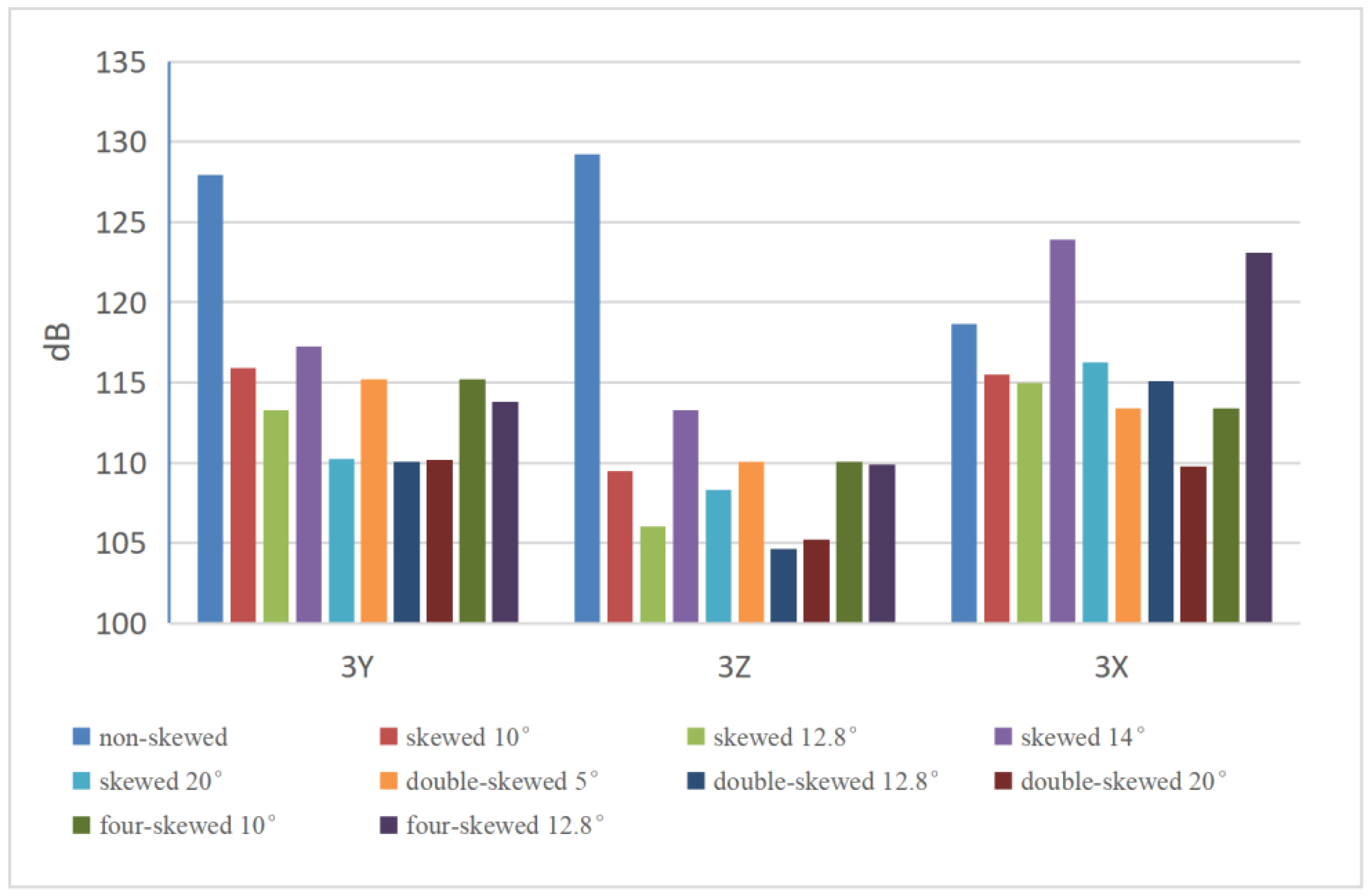
According to previous analysis, the optimum vibration skew slot of the motor is three stator teeth, i.e., the angle of the skew slot is 30°. However, it is difficult to produce such a large skew angle using conventional motor technology. In order to verify the optimum parameters of the skew vibration, the double-skew and four-skew slot methods can be used to increase the skew angle accordingly. The double-skew slot divides the whole rotor core into two symmetrical single skew slot rotors along the axial direction, and the double skew can double the skew angle of the single skew. The four-skew slot method can achieve a skew angle four times that of the single-skew method.
6. Conclusions
This paper described an analytical method for a skewed rotor induction motor to analyze the magnetic flux density distribution and calculate the electrical magnetic force. By converting the single-slot, double-slot, and four-slot rotor transformations into slot skew parameters, the effect of slot skew on the electromagnetic vibration damping of the motor was validated for all parameters. The described analytical method was verified by simulation results and experimental tests. The conclusions are as follows:
Motor vibration decreases as the skew slot angle increases, but vibration changes occur when a certain skew slot angle is reached. It can be assumed that there is an optimized skew slot angle within the permissible parameter range that can effectively reduce the electromagnetic vibration of the motor.
The variation analysis of skew coefficients in 36–28 motor rotors demonstrates that the skew coefficient directly reflects the amplitude variations of electromagnetic excitation forces. When the rotor is skewed by a specific angle, higher-order electromagnetic forces exhibit slight attenuation. Moreover, when the skew span covers three stator teeth, the forces at each order are weakened by approximately 5% on average, indicating the optimal condition. By analyzing motor vibrations through the skew coefficient, the amplitude relationships of electromagnetic vibrations under different optimization parameters can be determined, thereby enabling the selection of appropriate optimization parameters.
Experimental analyses and tests on rotors with skew angles of 0°, 10°, 12.8°, 14°, and 20° reveal that, the tooth harmonic amplitude varies with the skew factor, which is consistent with the theoretical analysis. Regardless of the skew configuration, the skew angle remains the predominant factor affecting electromagnetic vibrations in motors. As the skew angle increases, both the starting torque and the maximum torque of the motor gradually decrease. Consequently, when optimizing motor vibrations using skewed rotors, it is essential to evaluate comprehensively the interplay between motor performance and vibration characteristics and select suitable skew angle parameters.
Author Contributions
Conceptualization, methodology, D.K., B.J. and Y.X.; software, Y.X. and Z.L.; validation, Y.X., D.K. and Z.L.; formal analysis, investigation, resources, data curation, Y.X., D.K. and Z.L.; writing—original draft preparation, Y.X. and Z.L.; writing—review and editing, Y.X., D.K., Z.L. and B.J.; visualization, D.K.; funding acquisition, D.K. and B.J. All authors have read and agreed to the published version of the manuscript.
Funding
This work was supported by the National Natural Science Foundation of China under Grant 52071090; This work was supported by the National Natural Science Foundation of China 52201355; This work was supported by a program for scientific research start-up funds of Guangdong Ocean University.
Data Availability Statement
The original contributions presented in this study are included in the article. Further inquiries can be directed to the corresponding author.
Conflicts of Interest
The authors declare no conflicts of interest.
References
- Tsypkin, M. Induction motor condition monitoring: Vibration analysis technique—A practical implementation. In Proceedings of the 2011 IEEE International Electric Machines & Drives Conference (IEMDC 2011), Niagara Falls, ON, Canada, 15–18 May 2011; pp. 406–411. [Google Scholar]
- Gnaciński, P.; Hallmann, D.; Klimczak, P.; Muc, A.; Pepliński, M. Effects of Voltage Interharmonics on Cage Induction Motors. Energies 2021, 14, 1218. [Google Scholar] [CrossRef]
- Linkous, C.E. Effect of Skew on Induction Motor Magnetic Fields. In Transactions of the American Institute of Electrical Engineers; The American Institute of Electrical Engineers: New York, NY, USA, 1961; Volume 74, pp. 760–765. [Google Scholar]
- Deodhar, R.P.; Staton, D.A.; Miller, T.J.E. Modelling of skew using the flux-MMF diagram. In Proceedings of the International Conference on Power Electronics, Drives and Energy Systems for Industrial Growth, New Delhi, India, 8–11 January 1996; pp. 546–551. [Google Scholar]
- Afanasyev, Y.; Pashali, D.; Yushkova, O.; Zhuravlev, D. Investigation of the Rotor Slots Skew Effect on the Induction Motor Characteristics. In Proceedings of the 2021 International Conference on Electrotechnical Complexes and Systems (ICOECS 2021), Moscow, Russia, 16–18 November 2021; pp. 214–218. [Google Scholar]
- Gyselinck, J.J.C.; Vandevelde, L.; Melkebeek, J.A.A. Multi-Slice FE Modeling of Electrical Machines with Skewed Slots-the Skew Discretization Error. IEEE Trans. Magn. 2001, 37, 3233–3237. [Google Scholar] [CrossRef]
- Cheng, M.; Han, P.; Hua, W. General Airgap Field Modulation Theory for Electrical Machines. IEEE Trans. Ind. Electron. 2017, 64, 6063–6074. [Google Scholar] [CrossRef]
- Angst, G. Saturation Factors for Leakage Reactance of Induction Motors with Skewed Rotors. IEEE Trans. Power Appar. Syst. 1963, 82, 716–725. [Google Scholar] [CrossRef]
- Carbonieri, M.; Bianchi, N.; Alberti, L. Induction Motor Analysis Using Magnetostatic Finite Element Simulations Considering Skewing. In Proceedings of the 2019 IEEE International Electric Machines & Drives Conference (IEMDC 2019), San Diego, CA, USA, 12–15 May 2019; pp. 147–153. [Google Scholar]
- Zhang, J.; Zhang, H.; Ding, G.; Gao, R.; Long, R. Analysis of Skewed Angle Effects of Rotor in Switched Reluctance Motor on Electromagnetic Parameters Using FEM. Int. J. Appl. Electromagn. Mech. 2012, 40, 149–163. [Google Scholar] [CrossRef]
- Guo, D.; Shi, Q.; Wang, Y.; Zhang, X.; Shen, Q. Optimal Design of Rotor Structure for Vibration and Noise Reduction in Electric Vehicle Generator. Proc. Inst. Mech. Eng. 2024, 238, 4646–4658. [Google Scholar] [CrossRef]
- Jang, H.; Kim, H.; Liu, H.C.; Lee, H.J.; Lee, J. Investigation on the Torque Ripple Reduction Method of a Hybrid Electric Vehicle Motor. Energies 2021, 14, 1413. [Google Scholar] [CrossRef]
- Dedecan, H.; Ayçiçek, E.; Aydeniz, M.G. Investigation of Torque Ripple in Servo Motors with Different Magnet Geometries. Electronics 2025, 14, 1049. [Google Scholar] [CrossRef]
- Wang, C.; Bao, X.; Xu, S.; Zhou, Y.; Xu, W.; Chen, Y. Analysis of Vibration and Noise for Different Skewed Slot-Type Squirrel-Cage Induction Motors. IEEE Trans. Magn. 2017, 53, 1–6. [Google Scholar] [CrossRef]
- Darjazini, A.; Karimi, M.; Saeedinia, M.H.; Cheraghi, M. Vibration and Noise Analysis of Squirrel Cage Induction Motors with Double Non-Skewed Rotor Structure. In Proceedings of the 2022 13th Power Electronics, Drive Systems, and Technologies Conference (PEDSTC 2022), Tehran, Iran, 1–3 February 2022; pp. 212–217. [Google Scholar]
- Wang, X.; Zhang, Y.; Li, N. Analysis and Reduction of Electromagnetic Noise of Yokeless and Segmented Armature Axial Flux Motor. In Proceedings of the 2022 25th International Conference on Electrical Machines and Systems (ICEMS 2022), Chiang Mai, Thailand, 29 November–2 December 2022; pp. 1–6. [Google Scholar]
- Jung, J.W.; Kim, D.J.; Hong, J.P.; Lee, G.H.; Jeon, S.M. Experimental Verification and Effects of Step Skewed Rotor Type IPMSM on Vibration and Noise. IEEE Trans. Magn. 2011, 47, 3661–3664. [Google Scholar] [CrossRef]
- Zhu, H.; Zhou, G.; Chen, J.; Liu, H. Analysis and Study of Skewed Slot Tooth Distance on Low Electromagnetic Noise of Three-Phase Induction Motor with Squirrel Cage Rotor. In Proceedings of the 2012 Sixth International Conference on Electromagnetic Field Problems and Applications (ICEF 2012), Dalian, China, 19–21 June 2012; pp. 1–4. [Google Scholar]
- Petrov, I.; Hoffer, A.E.; Pyrhonen, J. Reduction of torque ripple in synchronous machines by quasi-skew-asymmetric rotor. In Proceedings of the 2020 International Conference on Electrical Machines (ICEM 2020), Gothenburg, Sweden, 23–26 August 2020; pp. 298–304. [Google Scholar]
- Yang, H.Y.; Lim, Y.C.; Kim, H.C. Acoustic Noise/Vibration Reduction of a Single-Phase SRM Using Skewed Stator and Rotor. IEEE Trans. Ind. Electron. 2013, 60, 4292–4300. [Google Scholar] [CrossRef]
- Kong, D.; Shuai, Z.; Li, W.; Wang, D. Electromagnetic Vibration Characteristics Analysis of a Squirrel-Cage Induction Motor under Different Loading Conditions. IEEE Access 2019, 7, 173240–173248. [Google Scholar] [CrossRef]
- Juha, P.; Tapani, J.; Valeria, H. Design of Rotating Electrical Mechines, 1st ed.; John Wiley & Sons, Ltd.: Oxford, UK, 2008; pp. 250–251. [Google Scholar]
| Disclaimer/Publisher’s Note: The statements, opinions and data contained in all publications are solely those of the individual author(s) and contributor(s) and not of MDPI and/or the editor(s). MDPI and/or the editor(s) disclaim responsibility for any injury to people or property resulting from any ideas, methods, instructions or products referred to in the content. |
© 2025 by the authors. Licensee MDPI, Basel, Switzerland. This article is an open access article distributed under the terms and conditions of the Creative Commons Attribution (CC BY) license (https://creativecommons.org/licenses/by/4.0/).


