1. Introduction
As electrical machine design is shifting towards high-efficiency, cost-effective topologies, coreless axial flux machines (CAFMs) are progressively emerging as potential candidates for some applications such as electric vehicles and wind turbines [
1]. The absence of ferromagnetic cores in the stator leads to reduced iron losses and no cogging torque, thus improving efficiency and control.
In the field of CAFMs, the word “coreless” may refer to the absence of iron cores in the stator, the rotor, or both. Those CAFMs with no iron either in the stator or the rotor can be named ironless axial flux machines (IAFMs). CAFMs may benefit from a larger power-to-weight ratio and higher compactness, showing a good potential for cost saving with the use of plastic and additive manufacturing [
2]. Furthermore, IAFMs exhibit high speed capabilities and simplified construction [
3]. However, IAFM architectures have been rarely studied, as well as rotor coreless architectures [
1]. In addition, most CAFMs have permanent magnets (PMs) in the rotor and non-overlapping coils in the stator. Regarding the stator and rotor arrangements,
Figure 1 illustrates different CAFM topologies: single-stator single-rotor (SSSR), double-stator single-rotor (DSSR), single-stator double-rotor (SSDR), and multi-stator multi-rotor (MSMR).
In order to predict the performance of conventional electrical machines, i.e., radial flux machines with iron, analytical models have been used traditionally as a first approach. Sizing equations based on lumped parameters are a widespread technique that correlates the machine dimensions with specifications and design constraints [
4,
5], thus leading to a straightforward comparison with other machine topologies such as axial and transverse flux machines [
6,
7,
8,
9]. In addition, some other analytical techniques are based on solving the differential equations of the magnetic field in the air gap [
10,
11,
12], thus offering more accurate results; however, their conceptual background and implementation become much more complex. Furthermore, some recent approaches have tried to find an equilibrium between conventional sizing equations and field calculations for radial and axial flux machines with iron cores [
13]. Nevertheless, conventional analytical approaches are not valid for IAFMs as, here, the flux path circulates entirely through air; therefore, the analysis of the magnetic field goes beyond the air gap region.
More recently, the theoretical study of CAFMs has been gaining wider attention.
Table 1 summarizes the state of the art of the analytical techniques that have been applied to CAFMs. It is shown that most CAFMs are SSDR topologies where the rotor has iron cores but not the stator. More specifically, IAFMs (i.e., with no iron either in the stator or the rotor) are clearly dominated by SSDR arrangements. Sizing equations have not been applied to IAFMs, as integral formulation methods are preferred. These methods are based on the surface charge model, using a nodal approximation similar to the finite element method. However, the implementation of these methods seems not immediate, as their mathematical background is complex. A more straightforward, generalizable model based on sizing equations is required for the preliminary sizing of IAFMs, parametric analysis, and comparison with other machine topologies, as IAFM performance with respect to conventional electrical machines remains unclear.
This paper presents the development and application of a novel analytical model of a DSSR-IAFM. The proposed model is based on an empirical analysis, first calculating the peak value of the no-load flux density produced by a single cylindrical magnet, and then a function is assumed to represent the field variations, based on static finite element simulations. The model is validated throughout this work with finite element computations and experiments. Furthermore, the method can be directly applied to single-sided IAFMs and could be refined to deal with SSDR-IAFMs.
The novelty of the work presented in this document lies in two aspects, according to
Table 1: the machine topology and the application of sizing equations to an IAFM. Firstly, regarding the machine topology, the literature on CAFMs mostly presents SSDR arrangements, while this paper presents a DSSR arrangement. Moreover, CAFMs are not IAFMs generally, as they used to have ferromagnetic cores on the rotor. Therefore, the DSSR-IAFM topology presented here is at the forefront within the CAFM literature. Secondly, sizing equations have not been explored for their application to IAFMs, but they exhibit some advantages such as their simplicity compared with integral formulation methods, which are difficult to understand and implement due to their complex mathematical background. Furthermore, sizing equations enable a direct comparison between different machine topologies (axial flux, radial flux, transverse flux, etc.), as carried out in this paper, where the performance of a DSSR-IAFM is compared with the performance of a radial flux machine, showing great accuracy.
The prototype used for experimental validations is illustrated in
Figure 2. The stator is formed by a three-phase winding of non-overlapping coils made of copper wires. In the rotor, cylindrical rare-earth PMs are used, as circular slots are easy to manufacture and there is a wide variety of cylindrical magnets on the market. Both the stator and rotor housings are made of 3D-printed plastic (resin), where some empty holes have been left in the center of the coils to facilitate natural cooling. This constitutes one of the simplest topologies of electrical machines, with a great potential for recycling and reuse [
26].
This document is structured as follows.
Section 2 presents the empirical modeling of the magnetic field in a DSSR-IAFM with no iron. In
Section 3, finite element modeling and prototyping are described, together with the experimental validation. Finally,
Section 4 concludes this paper with a brief summary.
2. Empirical Modeling of the No-Load Magnetic Field in a Double-Stator Single-Rotor Coreless Axial Flux Machine
The flowchart of the analytical calculation process based on sizing equations is summarized in
Figure 3. As IAFMs have no saliency due to the absence of ferromagnetic cores in the stator and the rotor, their torque density —where
is the gap diameter and
l is the pole length—under a first-harmonic analysis is proportional to the peak no-load flux density
, the RMS linear current load
A, and the rotor and stator winding factors,
and
(
1). Therefore, the validation of a sizing process can be limited to the no-load field (back-electromotive force), as it fundamentally determines torque density. Furthermore, the under-load operation of IAFMs is not expected to deviate significantly from (
1), as IAFMs have no cogging torque or iron losses.
First, starting from PM remanence and relative permeability
and
, the peak no-load flux density
produced by a cylindrical magnet is parameterized with two comprehensive non-dimensional factors that are useful for electrical machine sizing, such as the magnet-to-air length ratio
and the optimum magnet aspect ratio
. Then, the total air gap
is the sum of the rotor, air, and stator gaps
and half of the coil height
. The PM non-dimensional parameters and the total air gap length give the magnet diameter, radius, and height
,
, and
, and the pole length factor
determines the gap radius
(
2). According to sizing equations of AFMs, the optimum pole length ratio for maximum torque production is
[
27,
28]. Further details regarding the air gap and PM calculation are presented throughout
Section 2.
In addition, the coil width
is given by the current load
, the number of phases
m, current
, the number of stators
, the number of pole pairs
p, the number of turns per phase
, the wire diameter
, and the copper fill factor
(
3), (
4).
Finally, all the geometrical parameters can be implemented in a single static simulation using the finite element method (FEM) that gives the 3D variation of the magnetic field. This 3D field can be curve-fitted with an empirical function in a straightforward way, and then its integration in an electrical cycle gives the flux linkage waveform and the back-electromotive force (back-EMF) waveform , i.e., the induced voltage under no-load conditions. This set of equations can be solved iteratively in order to size the DSSR-IAFM from some given specifications (voltage, torque, power) with a very reduced computation time, e.g., the back-EMF simulations (one electrical period) for four different speeds took 9 s with the proposed method implemented in MATLAB R2019a (including postprocessing), while FEM analysis in Flux3D 21.2took 15 min (not including postprocessing).
2.1. Peak No-Load Flux Density in the Stator Coils
The magnetic field produced by a single cylindrical magnet in vacuum along its
z-axis is given by (
5), where the main parameters are referred from
Figure 4.
and
are the magnet remanence and relative permeability,
and
are the magnet height and radius, and
is the distance along the
z-axis from the circular surfaces of the cylinder.
In a DSSR-IAFM, the no-load flux density along the PM axis can be deduced in a similar way using the machine dimensions in the transverse plane (
Figure 5). More precisely, the magnetic field can be calculated in the middle point
C of the stator coil, defined by coordinate
as given by (
6).
and
denote the rotor and stator clearances for mechanical assembly,
is the real air gap, and
is the coil height in the axial direction.
Introducing the magnet-to-air length ratio
(
7) and the magnet aspect ratio
(
8), the peak value of the no-load flux density of a DSSR-IAFM can be expressed as a function of these two design parameters (
9). Moreover, it can be proved that the no-load field is maximum for an optimum aspect ratio of PMs
that can be calculated analytically from
(
10).
2.2. Comparison with Conventional Machines
In a conventional electrical machine with iron, the peak no-load flux density is given by (
11) [
9].
Comparing Equations (
9) and (
10) with
for DSSR-IAFMs, and (
11) for electrical machines with iron, it can be stated that for both cases, the peak no-load flux density depends only on the magnet properties and the magnet-to-air length ratio
. This model facilitates the comparison of DSSR-IAFMs with other machine topologies, as illustrated in
Figure 6, where the peak no-load flux density that can be achieved in a DSSR-IAFM has been expressed as a relative value with respect to an equivalent machine with iron, for the same
values.
Even in the most favorable cases, i.e., optimum , the peak no-load flux density in a DSSR-IAFM barely reaches 40% of the flux density in a conventional machine with iron. Moreover, optimum aspect ratios of PMs are lower than 1 for practical values of the magnet-to-air length ratio (); therefore, in order to produce maximum in a DSSR-IAFM, the rotor PMs should be larger in diameter than axially.
The reduced no-load flux density that characterizes DSSR-IAFMs, according to
Figure 6, has an effect when sizing the machine. Following (
1), DSRR-CAFMs require high current loads for volumetric torque production in order to compensate their low excitation field. This means that, in order to increase torque density, the number of turns in the stator and/or current have to be increased for a given machine diameter, thus complicating cooling and heat dissipation, as well as the allocation of the coils in the stator.
2.3. Reference Frames
Figure 7a illustrates the reference frames that have been used to model the magnetic field with the rotor moving. Electrical angles
are related to mechanical angles
through the number of pole pairs
p (
12). Reference
moves with the point
P of magnets, whereas reference
serves to define the integration points of the coil.
Q is an arbitrary point in space, whose coordinates in the global reference
can be transformed to other references, according to transformations that have been depicted in
Figure 7b.
In this way, the 3D magnetic field distribution, that is defined by function with respect to moving point P in reference , can be expressed in the coil reference . Then, the integration of the magnetic field along the coil surface will give the flux, as stated in next section.
2.4. No-Load Flux Linkage and Back-EMF in a Single Stator
The no-load flux linkage can be calculated by integrating the flux density
along the coil surface
(
13).
is a function that fits the 3D magnetic field, the distance
of each point in the domain is obtained for different rotor positions, applying the transformations of coordinates in
Figure 7b, and the trapezoidal surface of the coil has been parameterized in the reference frame
. Finally, the back-EMF follows (
14), where
is the number of turns in series (coil or stator) and
is the mechanical speed in rpm.
3. Finite Element and Experimental Validation
Table 2 summarizes the main parameters that have been adopted to size the DSSR-IAFM prototype with the proposed method, with
being the optimum value for
. In this paper, we deal with a small-size machine, with the outer diameter being lower than 5 cm, as this is a low-cost prototype. When sizing the machine, the current load has been chosen as a quite low value, compared to conventional values for radial flux machines in the literature, in order to avoid thermal issues. Moreover, in a DSSR-IAFM, the rotor movement helps significantly in evacuating heat from the windings; therefore, it can be assumed that natural cooling will not cause any overheating in the proposed machine.
FEM simulations have been conducted using Altair Flux3D 21.2 software.
Figure 8 shows the meshed model together with the boundary conditions. Three-dimensional geometries become mandatory for the finite element modeling of IAFMs, as their flux path is inherently three-dimensional. A second-order, extruded mesh has been used in the stator and rotor inner regions to improve the accuracy and reduce the computation time. The model has 256,643 volume elements and 374,368 nodes in total. Regarding the boundary conditions, the machine has to be modeled entirely in the axial direction, as the domain is not symmetric with respect to the
plane, because the stators are shifted in the circumferential direction. Furthermore, the magnetic field is assumed to be zero in infinity by use of an infinite box technique.
Figure 9 shows the DSSR-IAFM prototype and the experimental setup to determine the back-EMF, where the H-bridge converter drives a DC motor that moves the DSSR-IAFM as a generator.
3.1. Peak No-Load Flux Density
Figure 10 shows a sensitivity analysis that has been conducted in order to validate the analytical model proposed here for different values of the design parameters
and
. The peak no-load flux density has been expressed as a relative value with respect to PM remanence, showing good agreement between analytical calculations and FEM. In the case of the DSSR-IAFM, it can be stated that the flux density does not depend on the air gap length, as predicted by (
9) and (
10).
3.2. Empirical Curve-Fitting of the 3D Magnetic Field
Figure 11 shows the axial component of the no-load flux density in the coil plane
, obtained via FEM, with the machine at standstill. The peak value is 0.29 T, thus agreeing with previous analytical calculations. Moreover, it is shown that the field seems to decrease with distance
from the middle point of the magnet
P. Therefore, if an empirical function of
, say
, is adopted to model the 3D field, it can be expressed as a function of the peak value
and the rest of the parameters that affect
, as in conventional analytical modeling of electrical machines with iron, where the magnetic field produced by PMs is assumed to be rectangular, following the PM span [
9].
Figure 12 illustrates the no-load flux density along
, both from FEM and analytical models. In the latter case, a cosine variation of the magnetic field has been assumed (
15), up to a distance
where the field is null. A sensitivity analysis, analogous to that of
Figure 10, has shown that the analytical assumptions match FEM results for
values between 1.5 and 1.7, thus being in a narrow range.
Therefore, the 3D field of the DSSR-CAFM can be characterized with a certain accuracy using a function of only two parameters: the peak value of the no-load flux density
produced by a single magnet (
9) and the geometric factor
that accounts for the 3D descent of the magnetic field up to zero.
Figure 13 shows the magnetic field as obtained by this analytical model, for the rotor electrical angles
0°, 60°, and 120°. These are the initial position and two intermediate positions in an electrical half-period. They correspond to 0°, 30°, and 60° mechanical degrees, as the machine has two pole pairs, in accordance with
Table 2 and (
12).
3.3. No-Load Flux Linkage and Back-EMF per Stator
Figure 14 shows the no-load flux linkage per stator
as a result of analytical and FEM computations. In addition, in
Figure 15, the associated back-EMF at the rated speed (3000 rpm) has been depicted, together with its harmonic decomposition. It is shown that the fundamental harmonic of the back-EMF is well determined by the analytical model of the 3D field (
15), with the relative error being −6.5% with respect to experimental values. However, there is a significant contribution of the 3rd harmonic, which is even higher than the first harmonic according to FEM and experimental simulations. The analytical calculations give a 3rd harmonic of the back-EMF that is 24% lower than the experimental value, even though the flux density and no-load flux linkage waveforms seem to agree when comparing the analytical function and FEM. Nevertheless, the 3rd harmonic will be later eliminated by the use of the double stator, as explained in
Section 3.4, thus resulting in a more sinusoidal back-EMF.
Furthermore, the peak values of the 5th and 7th harmonics are lower than 5% of the first-harmonic; therefore, they are subsequently neglected in the analysis. The torque ripple that these harmonics could produce is outside the scope of this paper, as the aim is just to establish a sizing methodology based on the main harmonic contributions to the no-load magnetic field, from (
1).
Figure 13.
Magnetic field as given by analytical model, 3D views, and projections on plane, for different rotor positions: (a) , (b) , (c) .
Figure 13.
Magnetic field as given by analytical model, 3D views, and projections on plane, for different rotor positions: (a) , (b) , (c) .
Figure 14.
No-load flux linkage per stator, analytical and FEM.
Figure 14.
No-load flux linkage per stator, analytical and FEM.
In
Figure 16, the back-EMF per stator at different speeds has been depicted. As the proposed IAFM has no iron cores, the back-EMF is linear with speed in the whole range; therefore, the relative error of analytical and FEM models with respect to experimental values remains constant.
Figure 15.
Back-EMF per stator at rated speed: (a) waveform and (b) amplitude of the harmonics.
Figure 15.
Back-EMF per stator at rated speed: (a) waveform and (b) amplitude of the harmonics.
Figure 16.
Back-EMF of a single stator (RMS harmonics) with speed: (a) first harmonic and (b) third harmonic.
Figure 16.
Back-EMF of a single stator (RMS harmonics) with speed: (a) first harmonic and (b) third harmonic.
3.4. Cancellation of the Third Harmonic by Use of a Double Stator
If all the coils in a phase are series connected and the stators are shifted in the circumferential direction, some of the harmonics can be canceled. The shift angle
in electrical degrees is given by (
16), and this condition states that the corresponding harmonics to be canceled must be shifted 180° in the electrical domain. In the proposed DSSR-IAFM, the 3rd harmonics of the back-EMF have to be canceled as their magnitude is comparable to the fundamental, thus distorting the voltage waveform. Therefore, substituting
gives a minimum angular shift
, and therefore
in the mechanical domain.
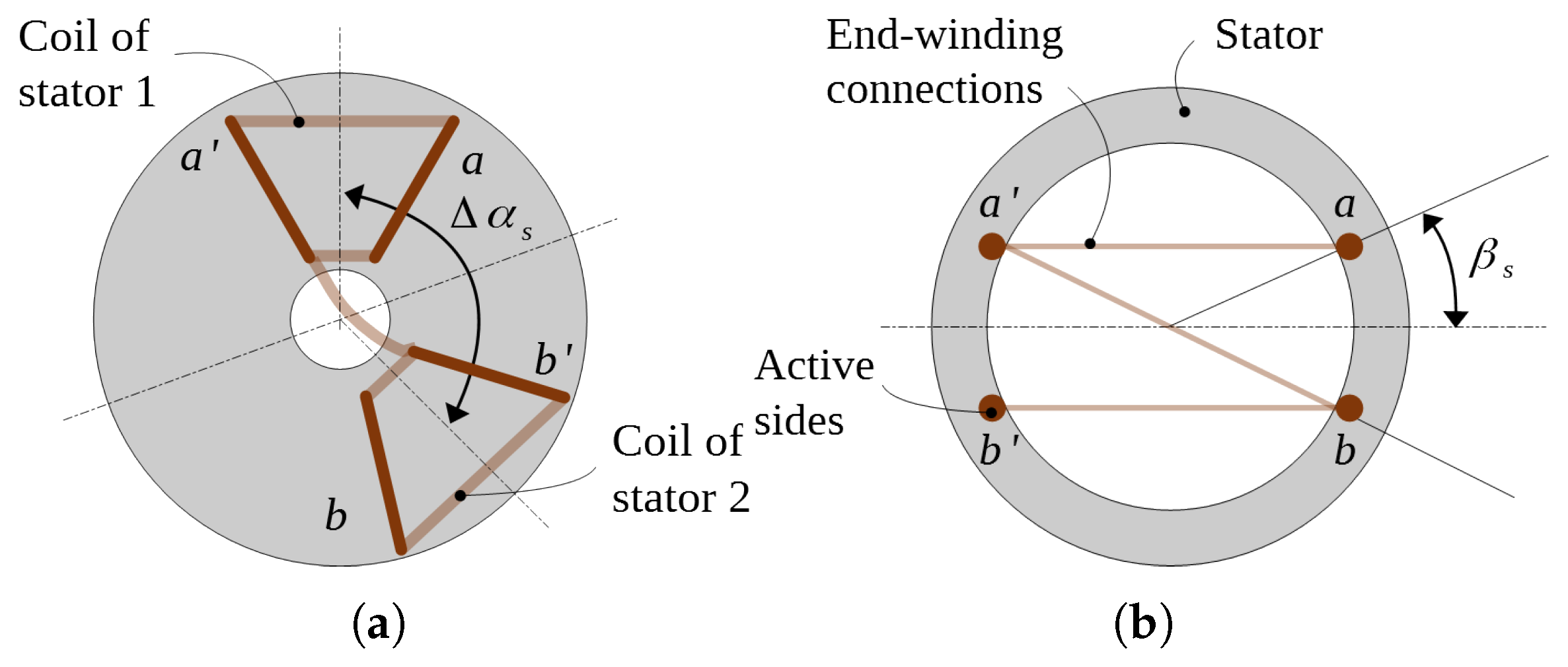
It should be noted that the selective elimination of harmonics in a DSSR-IAFM is equivalent to the short-pitching of coils in conventional radial flux machines, as illustrated in
Figure 17. The equivalence between stator shifting in DSSR machines and coil pitching in conventional machines is given by (
17)
The measured back-EMF of both stators with an angular shift
is depicted in
Figure 18. It is shown that the back-EMF is much more sinusoidal when the stators are connected in series, as the contribution of the 3rd harmonics is eliminated. Furthermore, the first harmonics of both stators are shifted
in the electrical domain, as expected, and the amplitude of the total back-EMF (first-harmonic) follows the definition of the stator winding factor
(
18), where that in the proposed CAFM equals 0.866.
The total harmonic distortion of the back-EMF, THD (
19), decreases from more than 90% to 9% comparing the single-stator analysis and the double-stator analysis (red and yellow lines versus green line in
Figure 18), thus proving the effectiveness of the angular shifting of both stators to reduce the harmonic content.
denotes the RMS value of the
h-th harmonic.
4. Conclusions
Ironless axial flux machines (IAFMs) benefit from the absence of iron losses and cogging torque, showing a good potential in terms of gravimetric power density and compactness. However, their analytical modeling is more complicated when compared with conventional machines, as in IAFMs, the 3D flux path closes entirely through air.
In this paper, the analytical modeling of a double-stator single-rotor IAFM (DSSR-IAFM) has been addressed starting from the calculation of the no-load peak flux density produced by a single magnet. The model is adequate for sizing purposes as it is based on algebraic equations and conventional parameters. It is shown that in a DSSR-IAFM, the peak no-load flux density depends on the magnet properties, the magnet-to-air length ratio , and the magnet aspect ratio . Moreover, these two parameters are related to each other for maximum field production. From analytical expressions, it is possible to state that in a DSSR-IAFM, the no-load peak flux density barely reaches 40% of the flux density in a conventional machine with iron, thus affecting volumetric torque density. Furthermore, the analytical expressions to calculate the peak no-load peak flux density have been validated with a sensitivity analysis using the finite element method (FEM).
Preliminary simulations using FEM show that the 3D variations of the flux density produced by a single magnet can be fitted empirically using a cosine function with a certain accuracy. Therefore, the no-load flux linkage and the back-EMF can be calculated by defining appropriate reference frames and integrating the 3D waveform of the no-load flux density.
The analytical model has been validated via FEM and experiments, focusing on the back-EMF harmonics. The fundamental harmonic of the back-EMF per stator given by the analytical model is 6.5% lower than the experimental value; however, the accuracy of the proposed model should be improved in order to represent the 3rd harmonic with higher accuracy. Furthermore, the double stator enables the cancellation of some back-EMF harmonics in a straightforward way, with an accurate angular shift between both stators. In this case, the 3rd harmonic is eliminated as its magnitude is comparable to the fundamental, resulting in a sinusoidal back-EMF.
In sum, the analytical model for DSSR-IAFMs that is presented in this paper shows a good accuracy with a reduced computation time and effort compared to the finite element method, also avoiding complex formulations of previous analytical models. Furthermore, the method can be directly applied to single-sided IAFMs with cylindrical magnets. As a future research line, the model could be refined to deal with single-stator double-rotor IAFMs, including under-load operation.


 ,
, 


