Article

Development of a Pipeline-Cleaning Robot for Heat-Exchanger Tubes

1
China Nuclear Power Engineering Co., Ltd., Beijing 100048, China
2
School of Engineering, China University of Petroleum (Beijing) at Karamay, Karamay 834000, China
*
Author to whom correspondence should be addressed.
Electronics 2025, 14(12), 2321; https://doi.org/10.3390/electronics14122321
Submission received: 28 March 2025 / Revised: 22 April 2025 / Accepted: 30 April 2025 / Published: 6 June 2025
(This article belongs to the Special Issue Intelligent Mobile Robotic Systems: Decision, Planning and Control)

Abstract

:
Cleaning operations in narrow pipelines are often hindered by limited maneuverability and low efficiency, necessitating the development of a high-performance and highly adaptable robotic solution. To address this challenge, this study proposes a pipeline-cleaning robot specifically designed for the heat-exchange tubes of industrial heat exchangers. The robot features a dual-wheel cross-drive configuration to enhance motion stability and integrates a gear–rack-based alignment mechanism with a cam-based propulsion system to enable autonomous deployment and cleaning via a flexible arm. The robot adopts a modular architecture with a separated body and cleaning arm, allowing for rapid assembly and maintenance through bolted connections. A vision-guided control system is implemented to support accurate positioning and task scheduling within the primary pipeline. Experimental results demonstrate that the robot can stably execute automatic navigation and sub-pipe cleaning, achieving pipe-switching times of less than 30 s. The system operates reliably and significantly improves cleaning efficiency. The proposed robotic system exhibits strong adaptability and generalizability, offering an effective solution for automated cleaning in confined pipeline environments.

1. Introduction

In recent decades, advances in science and technology have driven researchers across various disciplines to focus increasingly on robotics. The field has evolved from the development of simple serial and parallel manipulators [1] to more sophisticated collaborative robots. With the maturation of control theory, the challenges associated with robot control have been significantly reduced. After years of continuous development, the family of robotic systems has expanded substantially. In addition to robots that indirectly assist humans, a range of systems have been developed that interact directly with the human body. For instance, Zhao et al. [2] proposed a motion rehabilitation robot designed to guide patients’ upper limbs in performing targeted movements to support physical recovery. These robotic systems have brought tangible improvements to quality of life. Collaborative robots, which are currently receiving growing attention, have also benefited from the integration of vision-based perception frameworks [3,4], further enhancing their intelligence and adaptability in complex environments. The rapid development of robotic systems has had a pronounced impact on industrial applications. Pipelines, as a critical infrastructure for transporting industrial fluids, are often exposed to harsh outdoor environments and are prone to corrosion and wear. Wang et al. [5] and John et al. [6] noted that pipeline damage can lead to severe consequences, such as leakage, fire, or explosion. Therefore, routine inspection and maintenance are essential for ensuring the safety, longevity, and reliability of pipeline systems. Traditional pipeline inspection and maintenance methods rely heavily on manual operation, which is often inefficient, risky, and impractical for confined or complex geometries. Many industrial pipelines feature small diameters and intricate structures that are inaccessible to human workers. Shao et al. [7] emphasized the operational challenges posed by special pipeline configurations such as vertical shafts, variable diameters, bends, branches, and microtubes. These factors underscore the need for robotic systems that are specifically designed for pipeline environments. The development of such robots holds great promise for improving the efficiency, safety, and effectiveness of pipeline inspection and cleaning tasks in real-world engineering applications.
The emergence of robotic pipeline-cleaning solutions has brought a transformative shift to traditional pipe maintenance methods. Equipped with advanced robotic technologies and intelligent sensors, modern pipeline robots are capable of navigating complex pipe networks to autonomously perform cleaning tasks. Their compact design and high mobility enable effective inspection and cleaning of both the internal surfaces of small-diameter pipelines and their external components in constrained environments. Extensive research has been devoted to the development of pipeline robots. Kahnamouei et al. [8] and Jang et al. [9] have provided comprehensive overviews of their evolution over the past few decades. These robots have been widely deployed in sectors such as oil and gas, sewer networks, and wastewater treatment systems, where they are capable of performing challenging tasks, including welding, sampling, and cleaning. According to Miyake et al. [10], pipeline robots can be categorized into seven types based on their locomotion mechanisms: wheeled, tracked, walking, spiral, insect-like, and snake-like robots. These systems achieve mobility within pipelines by leveraging gravity or frictional forces generated between the robot body and the pipe wall. Shen et al. [11], for instance, proposed a parallel walking-type pipeline robot that realizes in-pipe locomotion through a coordinated legged mechanism. To address the aforementioned challenges of navigating complex pipeline geometries, Zheng et al. [12] introduced a highly adaptive robot with superior obstacle avoidance capabilities. Their system demonstrated reliable operation across various complex environments, including funnel-shaped pipes, variable diameters, gaps between sections, T-junctions, C-shaped bends, and pipelines with internal obstructions. Once the mechanical design is completed, the integration of appropriate control strategies [13,14] enables effective motion coordination and task execution within such constrained pipeline conditions. Xu et al. [15] designed a pipeline robot equipped with magnetic hemispherical wheels to accommodate pipes with varying curvatures. Helan Vidhya et al. [16] proposed a robotic cleaning system specifically for air-conditioning ducts. Momma et al. [17] developed a cleaning device utilizing a multi-stage planetary gear mechanism to remove grease deposits from kitchen pipelines with various geometries. Tanihira et al. [18] introduced a snake-like robot featuring a long brush that, in combination with the robot’s locomotion, enables comprehensive cleaning of the pipe’s inner surface. Despite the notable cleaning capabilities demonstrated by these robots across multiple applications, several limitations persist. Beyond the challenges posed by complex pipeline structures, the actual cleaning performance of pipeline robots remains a critical concern—particularly when dealing with stubborn contaminants. Most existing systems exhibit poor adaptability and unstable performance, making it difficult to ensure consistent cleaning quality or evaluate cleaning effectiveness in real time. To diversify cleaning strategies and maximize operational efficiency, Lee et al. [19] developed a rotary pigging device incorporating rotating blades. Liu et al. [20] investigated a pipe-cleaning robot specifically designed for natural gas pipelines. However, systems that rely solely on high-pressure water jets or chemical agents may be unsuitable for certain pipe materials or operating environments. Moreover, such approaches typically lack sufficient intelligence and adaptability, limiting their ability to autonomously optimize cleaning parameters or recover from failures. While some researchers have explored robotic designs suitable for ultra-narrow pipes, such as the sub-centimeter pipeline inspection robot with a diameter of less than 10 mm, driven by smart materials proposed by Tang et al. [21]; the highly adaptive soft robot developed by Li et al. [22] that is capable of climbing along the exterior of millimeter-scale pipelines; and the gas pipe robot by Roh et al. [23] that was designed for 4-inch internal diameters, most existing systems adopt monolithic designs. These are primarily tailored for navigation, localization [24], or inspection tasks and often lack integrated control strategies. Consequently, there is limited research focused on pipeline robots specifically engineered for narrow and confined environments. More critically, among those that do exist, few systems are designed for tasks beyond detection or positioning, such as pipeline cleaning [25], which remains a significant technical gap. In practical applications, the heat-transfer tubes of industrial heat exchangers often suffer from fouling, corrosion, or blockage during long-term operation, leading to a severe decline in thermal efficiency. Traditional manual or semi-automated cleaning methods are inadequate in terms of efficiency, adaptability, and safety. This issue becomes particularly pronounced in compact and structurally complex environments, where the diameter of heat-exchanger tubes is typically below 10 cm. Therefore, developing a solution for efficient, stable, and automated cleaning of these tubes presents a pressing engineering challenge.
Despite significant advancements in the development of pipeline-cleaning robots, three fundamental scientific challenges remain unresolved:
(1)
The stability and adaptability of robot motion in confined pipelines are still limited, often resulting in slippage or jamming;
(2)
Due to variations in pipe diameter and spatial constraints, existing cleaning mechanisms often fail to reach and effectively clean the deep or branched regions of heat-exchanger tubes;
(3)
Many current systems lack real-time sensing and feedback control, making precise alignment and autonomous operation difficult to achieve.
These challenges are particularly pronounced in heat-exchanger applications, where tubes are prone to fouling and blockage within narrow industrial environments. Therefore, this study aims to develop a robotic cleaning system with high adaptability, intelligent feedback control and mechanical flexibility to systematically address these scientific and engineering issues.
To address the aforementioned challenges, this study proposes a simplified and efficient robotic cleaning mechanism that integrates mechanical structure, hardware components, and software control to achieve continuous movement of the robot within the primary pipe and flexible insertion of the cleaning arm into heat-exchanger tubes for effective internal wall cleaning. The proposed robot features a modular split design consisting of a main robotic body and a flexible mechanical arm. The main body is capable of traversing the primary pipeline and carrying the flexible arm to the cleaning site, while the arm executes the cleaning operation inside the target heat-transfer tube. To enable stable positioning within the primary pipe, the robot adopts a passive variable-diameter mechanism—commonly used in pipeline robots [26,27]—which allows the body to conform tightly to the inner walls of the pipe. The system is equipped with a camera-based visual positioning module to assist in navigation and alignment. The flexible mechanical arm is driven forward by a dedicated motor integrated into the main body, allowing it to enter the narrow heat-exchanger tubes. With the assistance of visual feedback and the application of conventional high-pressure water jets combined with brush cleaning, the system achieves precise and effective removal of internal fouling. This approach offers a robust and practical solution for automated cleaning of confined pipeline environments.
This paper presents a comprehensive study on an intelligent robotic system designed for cleaning heat-exchanger pipelines. Section 2 focuses on structural adaptability, detailing the mechanical design and optimization of the robot body to accommodate narrow and complex pipeline environments. Section 3 conducts a systematic kinematic modeling and analysis of the driving, pushing, and alignment mechanisms, deriving the force characteristics, motion behavior, and motor torque requirements of each unit. Section 4 develops an integrated control system that combines image-based recognition and feedback control strategies to enable autonomous positioning and cleaning control. Section 5 establishes a simulated experimental platform to evaluate system performance and cleaning efficiency through tasks such as mother pipe navigation and sub-pipe cleaning. Finally, Section 6 summarizes the study and outlines future research directions, including structural lightweighting and further enhancement of wireless-control technologies.

2. Robot Structural Design

This section presents the overall mechanical design of the proposed pipeline-cleaning robot, covering its adaptive structure for different pipe environments, driving mechanism, flexible pushing unit, alignment system, and cleaning-brush assembly. The design aims to ensure high stability, strong maneuverability, and efficient cleaning performance in complex pipeline systems, while also incorporating waterproof features to operate reliably in potentially water-filled environments.

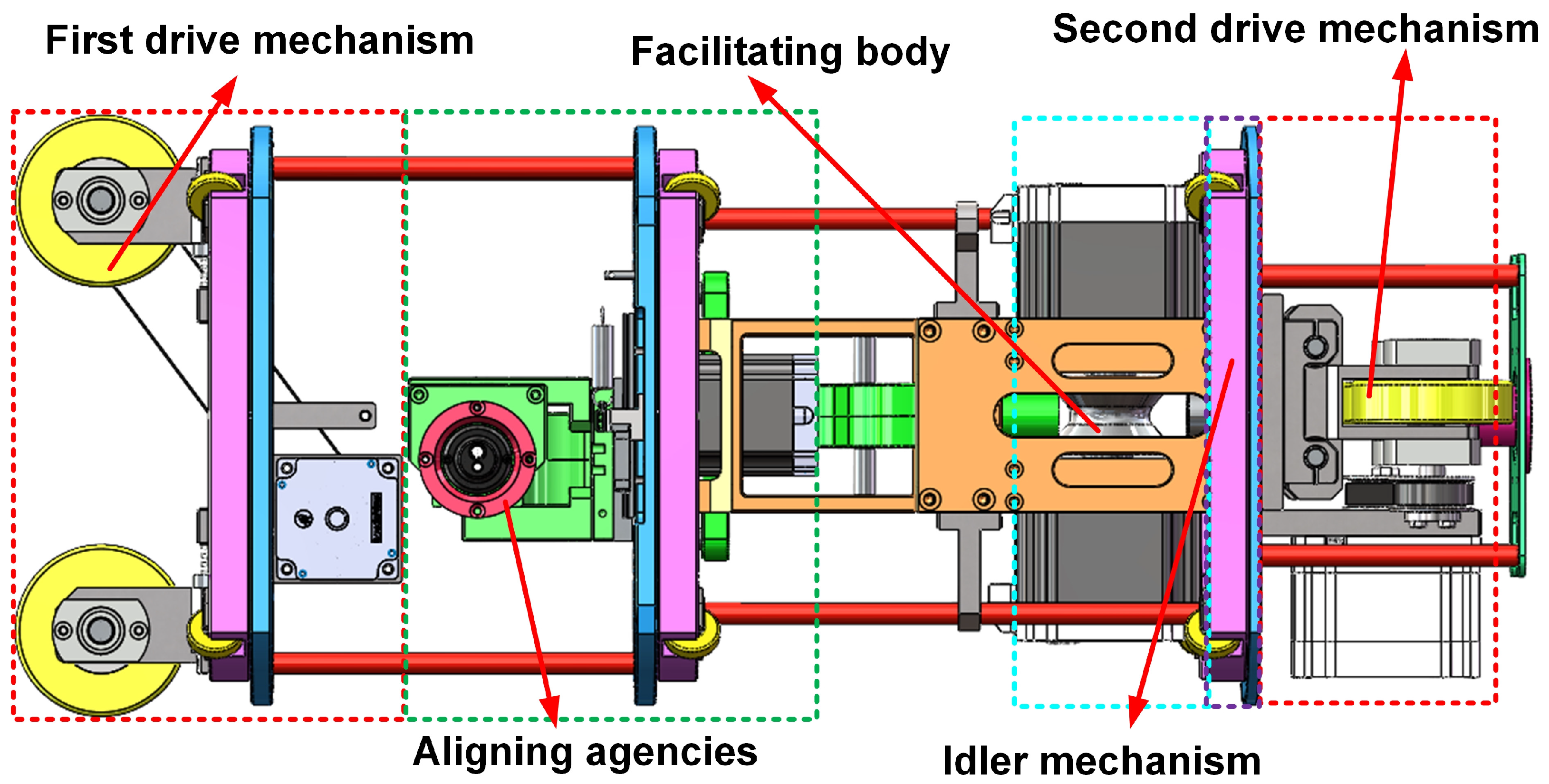
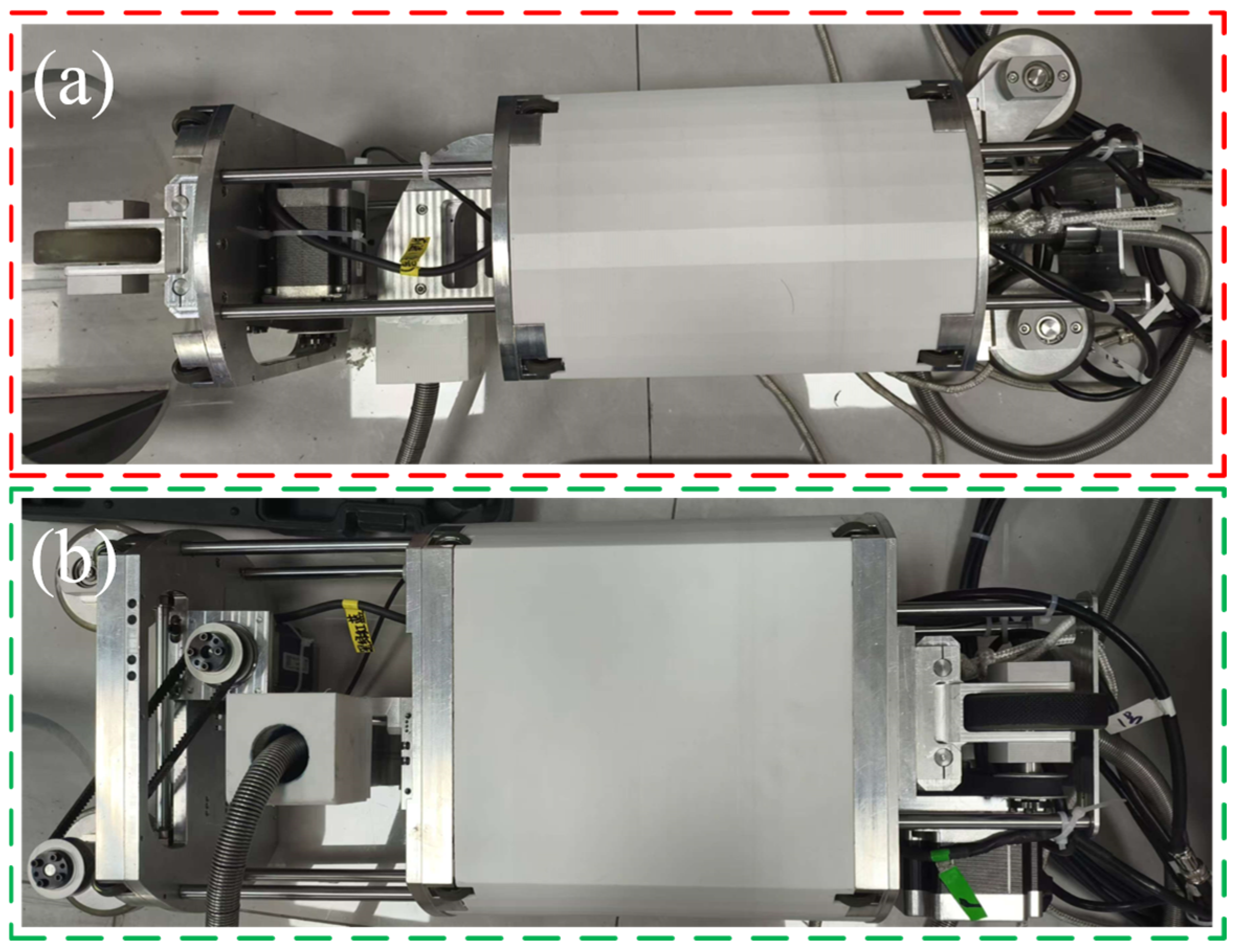
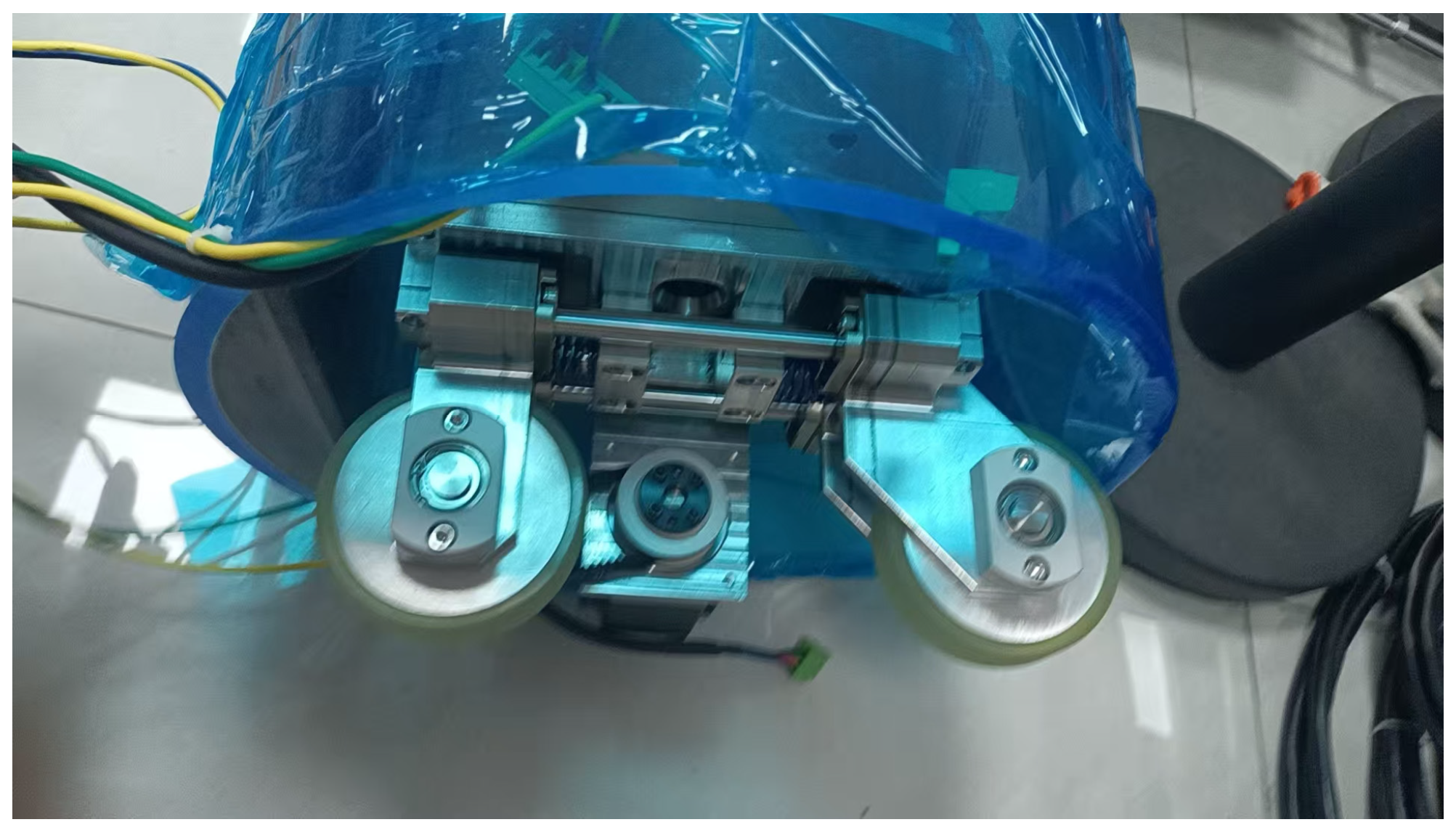
2.1. Mechanical Structure Design

Given that this study targets the cleaning of straight-type primary tubes in heat-exchanger systems, the robot’s mechanical structure and control strategy are primarily designed and validated for narrow, linear, and non-branching pipeline environments. The robot’s posture and dimensions within the pipeline are critical for ensuring operational stability and cleaning efficiency. As pipeline configurations vary, different structural standards must be considered—including straight segments, elbows, branches, and junctions [28]. Improper structural design may result in operational failures, the most common being the robot jamming inside the pipe [29]. Therefore, careful consideration of the robot’s geometry, size, and adaptability is essential to ensure effective maneuverability within constrained spaces. Most modern wheeled pipeline robots adopt diameter-adaptive mechanisms. As reported by Rusu [30], typical solutions include spring-supported, worm-and-gear, lead screw–nut pair, and scissor-lift-based diameter adjustment mechanisms [31]. In addition to these rigid structures, flexible passive adjustment mechanisms have also demonstrated promising adaptability. For instance, Jiang [32] proposed a soft modular pipeline robot capable of navigating through unstructured pipeline networks. The overall structural design of the robot proposed in this study is shown in Figure 1. A spring-supported passive diameter adjustment mechanism is adopted to accommodate variations in pipe diameter, as illustrated in Figure 2. The robot is composed of a driving system (consisting of primary and secondary drive modules), a flexible arm propulsion mechanism, a camera-guided alignment unit, an idler support structure, and a cleaning-brush assembly. To support cleaning tasks in potentially water-filled environments, the entire system is waterproof, offering resistance to large-area water exposure and short-term immersion.
The passive diameter-adjustment mechanism of the proposed robot consists primarily of spring seats and linear compression springs, which are symmetrically embedded in two pairs of main driving wheels and six pairs of idler wheels. Prior to insertion into the primary pipe, the springs remain in a naturally extended state. Upon being pushed into the pipe, the wheel assemblies undergo radial compression due to the constraint imposed by the pipe walls, resulting in passive spring compression. This mechanism enables the robot to achieve elastic wall contact and stable structural support within the confined pipe environment. To ensure sufficient radial support and structural stability, the springs used for the main driving wheels are configured with higher stiffness than those in the idler assemblies. The stiffer springs provide the primary support and fixation, while the softer springs in the smaller idler wheels offer supplementary support. This design effectively accommodates heat-exchanger pipes with internal diameters ranging from 275 mm to 300 mm. It ensures adequate wall-adhering force and motion stability without relying on complex active mechanisms, thereby enhancing the overall robustness and general applicability of the system.
To achieve adaptive radial fixation, two types of compression springs are employed in the structure. The main wheels are equipped with YSWC-D17-L30 compression springs (outer diameter, 17 mm; free length, 30 mm) with a stiffness of 18.16 N/mm, provided by Dongguan Yiheda Automation Co., Ltd. (Dongguan, China), which offer the primary radial support. In contrast, the auxiliary rollers use YWB-D4-L15 springs (outer diameter, 4 mm; free length, 15 mm) with a lower stiffness of 4.76 N/mm, serving to enhance wall-adherence stability. The structural design ensures that the working compression of the springs remains within 30–50% of their free length, a range that provides sufficient preload while allowing for dynamic deformation, thus preventing structural overload. In its natural (uncompressed) state, the wheel module’s outer diameter slightly exceeds 300 mm; upon insertion into the pipeline, it passively compresses to slightly below 275 mm, allowing automatic diameter adaptation during entry. The dimensions and stiffness values of the springs were selected based on the pipe’s geometric tolerance, surface friction characteristics, and structural clearance requirements, ensuring stable wall contact without the need for active adjustment mechanisms.
As illustrated in Figure 3, the drive system consists of two symmetrically arranged units—the primary and secondary drive modules—each comprising a timing belt transmission mechanism that includes motors, belts, pulleys, and multiple support shafts. All pulleys share the same specifications. These two modules are mounted in an orthogonal cross-configuration, which improves traction stability and enhances the robot’s adaptability on uneven inner pipe surfaces. A fixed pre-tensioning strategy is adopted in the transmission design, where appropriate shaft spacing is preset during assembly to establish belt tension, eliminating the need for auxiliary tensioning components. Throughout experimental testing, no issues, such as belt loosening, slippage, or disengagement, were observed, confirming the reliability and practicality of this approach for the given structural configuration.
The primary and secondary drive modules each consist of a displacement drive unit and a rotational drive unit. The displacement drive mechanism is responsible for actuating the drive wheels and enabling the translational movement of the pipeline-cleaning robot. Specifically, the robot’s linear propulsion is achieved by the displacement motor driving a timing belt, which in turn transmits torque to the drive wheels. The forward or backward motion of the robot is controlled by adjusting the rotation direction of the displacement motor.
As illustrated in Figure 4, the propulsion mechanism comprises two independent motors that synchronously drive the cam and concave rollers. The radial clamping force generated between the rollers converts the rotational torque into linear thrust, enabling the flexible arm to move forward and backward along the direction of the sub-pipe. To enhance durability in humid and corrosive environments, the surfaces of both rollers are coated with polyurethane over aluminum alloy. The polyurethane material, selected and customized by the supplier for the intended cleaning application, has a Shore A hardness rating of 95 and offers excellent wear resistance and structural stability. In multiple-cycle propulsion experiments, no noticeable wear or degradation was observed on the roller surfaces, demonstrating the mechanism’s reliability and reusability. The alignment mechanism, as shown in Figure 5a, primarily consists of a rack; a gear; a linear guide mounting plate; a stepper motor; and the second key component, namely the cleaning-brush head. The rack and gear are connected via the guide mounting plate, and the motor–rack assembly allows for vertical adjustment of the cleaning brush, thereby enabling precise up-and-down alignment during the cleaning process.
As shown in Figure 5b, the cleaning-brush head comprises helical bristles, a flexible water pipe, a vibration module, and a miniature camera. The flexible pipe is connected to a high-pressure water source and is capable of ejecting high-pressure jets to dislodge contaminants from the inner wall of the pipe and flush out residues after cleaning. The integrated vibration module enhances the cleaning efficiency by inducing oscillatory motion during brushing, thereby improving the contact dynamics between the bristles and the pipe wall. The miniature camera enables real-time visual processing and precise positional feedback, supporting the vision-guided alignment and control functions of the cleaning system.

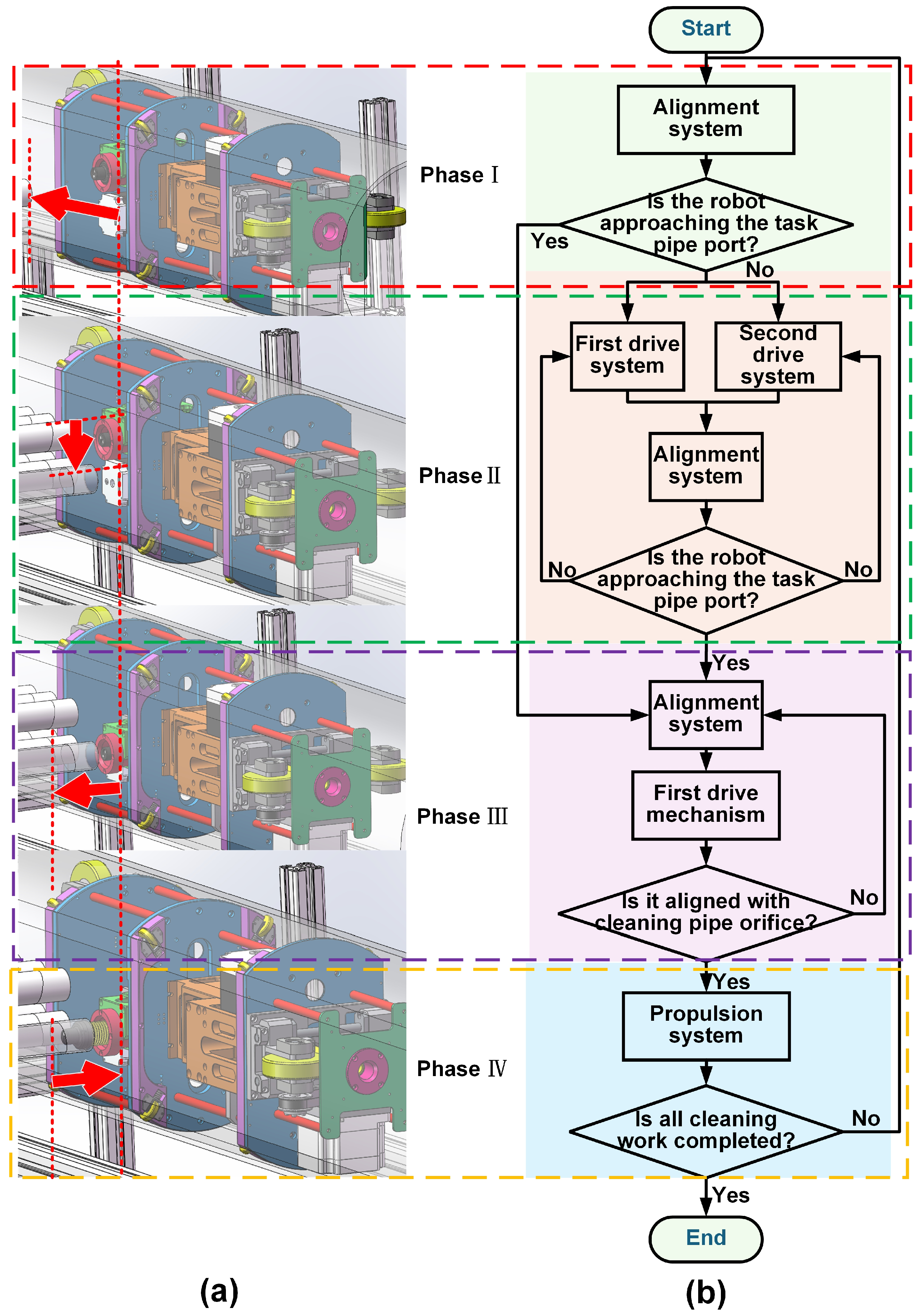
2.2. Working Principle

As illustrated in Figure 6, the pipeline-cleaning process comprises four main stages: horizontal locomotion along the main tube, vertical alignment with sub-tube inlets, forward insertion of the cleaning-brush head, and retraction upon task completion.
Stage I: The robot travels horizontally along the main tube using its primary and secondary drive modules. The passive diameter-adjusting wheels ensure stable wall contact, while the auxiliary rollers provide lateral support. A miniature onboard camera continuously monitors the internal pipe environment to determine proximity to the sub-tube inlets.
Stage II: Once a sub-tube inlet is detected, the alignment module is activated. Through the gear–rack mechanism, the brush head is vertically adjusted to align with the inlet. The visual system provides real-time feedback to confirm accurate alignment.
Stage III: After successful alignment, the robot maintains its position while the propulsion system is engaged. The flexible cleaning arm—equipped with a high-pressure water brush and vibration module—is inserted into the sub-tube to perform the cleaning operation.
Stage IV: Upon completion, the propulsion system retracts the cleaning arm, and the robot resumes forward motion to locate the next sub-tube. Throughout the entire process, the miniature camera continuously captures pipeline imagery, which is used for post-cleaning evaluation either manually or through algorithmic analysis to determine whether a secondary cleaning pass is required.

3. Kinematic Analysis

To ensure reliable operation and mechanical stability of the pipeline-cleaning robot under complex working conditions, this study conducts quasi-static modeling and analysis of its core execution mechanisms from both kinematic and dynamic perspectives. Given the robot’s low operating speed and limited structural degrees of freedom, a modular modeling approach is adopted to separately analyze the driving, pushing, and alignment mechanisms. For each module, mechanical expressions and motor torque requirements are derived for horizontal motion, flexible arm propulsion, and vertical alignment, respectively, providing a theoretical foundation for mechanism design and control parameter selection.
The modeling process is based on classical Newtonian mechanics, rigid-body dynamics, and tribological principles, and further incorporates the specific characteristics of the transmission system. Key parameters involved in the models—such as friction coefficient ( μ ), transmission efficiency ( η ), spring stiffness, and safety factor ( S )—are obtained from CAD structural modeling, experimental measurements, or manufacturer datasheets. Specifically, the friction coefficient, μ , is selected based on engineering experience for steel–rubber and rubber–silicone contacts (ranging from 0.35 to 0.5); transmission efficiency, η , is set at approximately 0.85, consistent with general belt and gear system guidelines; and the safety factor, S , is set to 1.5 to account for load fluctuations and design redundancy. These values are grounded in physical reasoning and practical engineering applicability, making them suitable for the quasi-static modeling of the robot under “low-speed, periodic, moderate-load” operating conditions. The resulting models ensure both computational feasibility and robustness.
Note on variable definitions and units:
Unless otherwise specified, the variables used in the formulas are defined as follows:
  • Force ( F ): Newton (N).
  • Mass ( m ): kilogram (kg).
  • Acceleration ( a ): meters per second squared (m/s2).
  • Velocity ( V ): meters per second (m/s).
  • Torque ( T ): Newton meter (N·m).
  • Radius/diameter ( R , D ): meter (m).
  • Pressure ( P ): Pascal (Pa).
  • Area ( A ): square meter (m2).
  • Angular velocity ( n ): revolutions per minute (rpm), unless otherwise stated.
  • Friction coefficient ( μ ), efficiency ( η ), and safety factor ( S ): dimensionless.
All symbols are used consistently throughout the modeling section. Parameter values are derived from CAD models, empirical tests, or datasheet specifications, as detailed in each subsection.

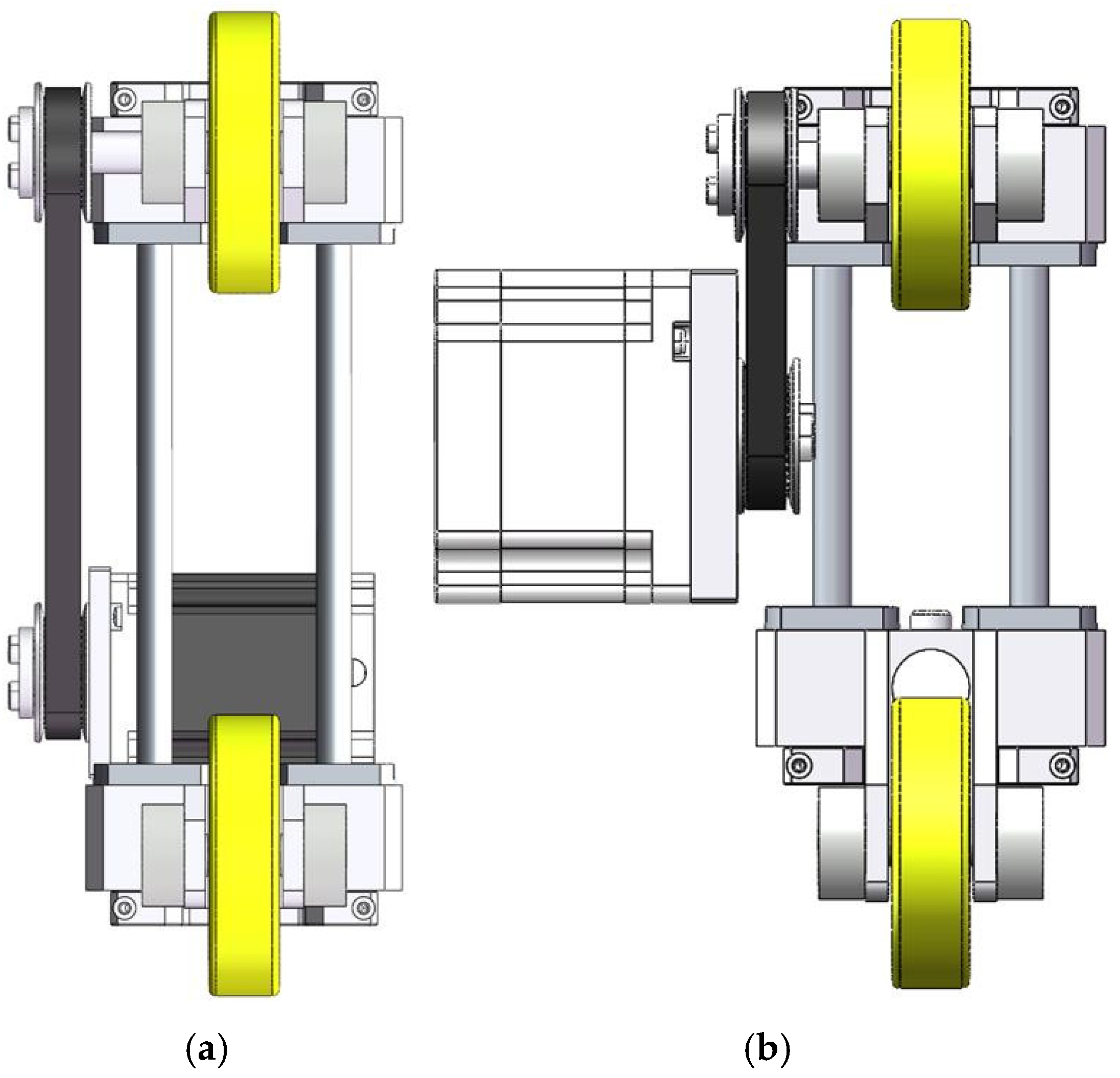
3.1. Drive-Mechanism Analysis

This section focuses on the mechanical modeling and torque analysis of the driving system, which enables the robot to perform horizontal motion within the primary pipeline. The discussion includes the structural composition of the drive units, force analysis, wheel group configuration, and its influence on locomotion stability. The goal is to provide a theoretical basis for motor selection and overall dynamic performance evaluation.
To ensure robust mobility within the pipe, the robot employs a dual-drive configuration comprising two independent driving modules (referred to as the first and second drive units), as illustrated in Figure 3. The wheel assemblies of the two modules are arranged in a cross-shaped (X) configuration, which effectively mitigates common issues, such as slippage or jamming, caused by inner wall irregularities due to fabrication or installation defects. This arrangement significantly enhances the system’s adaptability and reliability in uneven pipeline environments.
Based on a comparative analysis of available drive strategies, a “primary–auxiliary” wheel configuration was adopted. In this design, the rotational motion of each motor is transmitted via synchronous belts to the active wheels, converting it into forward linear motion. These two driving modules are symmetrically installed at both ends of the robot body to ensure balanced load distribution and improve locomotion stability. Considering the robot’s overall size and weight, appropriate motors were selected to meet the required torque demands, while also supporting RS485 communication for integration into the control system.
During horizontal motion, the robot is subject to three primary forces: (1) frictional force, F f , between the wheels and the pipe wall; (2) gravitational component, F S , due to possible pipe inclinations; and (3) inertial force, F a , caused by acceleration. According to Newton’s second law, the force equilibrium along the horizontal axis can be described as follows:
F f = μ × m × g
F s = m × g × s i n θ
F a = m × a
F t = F f + F s + F a
In the force analysis, the following parameters are defined:
  • μ is the friction coefficient between the wheel group and the inner wall of the pipeline (set as 0.35 in this study, based on typical engineering values for steel–rubber contact);
  • m is the total mass of the robot (approximately 25 kg, measured by weighing);
  • g is the gravitational acceleration (9.81 m/s2);
  • θ is the inclination angle of the pipeline (default is 0°, but retained as a variable to account for extreme conditions);
  • a is the linear acceleration of the robot during startup or speed transitions (determined by actual control parameters).
In practical deployment, the primary pipe is fixed on a horizontal experimental platform. Therefore, the influence of inclination can be reasonably neglected by setting θ = 0 . Under this assumption, the gravitational component, F S , becomes negligible, and the total driving force is simplifies as follows:
F t = F f + F a
Once the total required driving force, F t , for the robot is determined, it is necessary to further derive the traction force and torque required from each individual drive unit. Given the cross-shaped wheel arrangement (as illustrated in Figure 7), the traction load is symmetrically distributed, and each drive shaft is responsible for half of the total driving task. Therefore, the traction force required by a single shaft can be expressed as follows:
F a s = F t 2
Due to the contact angle between the wheel axle and the pipe surface being approximately 45°, the traction force must be decomposed according to the contact geometry between the wheel and the pipe wall. The effective traction component acting along the motor shaft direction, denoted as F t 1 , can thus be expressed as follows:
F t 1 = F a s cos θ ( θ = 45 ° )
According to the definition of torque T = F × r , and considering the transmission efficiency, η , and safety factor, S , the minimum output torque required from the driving motor, denoted as T m , can be expressed as follows:
T m = F t 1 × R w × S μ × η
where R w denotes the radius of the drive wheel, which is set to 80 mm based on structural design specifications. The friction coefficient, μ , between the wheel and the inner wall of the pipe is empirically set to 0.35. The transmission efficiency, η , accounting for both the timing belt and wheel assembly, is approximately 0.85. The safety factor, S , which is incorporated into motor selection to account for load fluctuations and operational uncertainties, is set to 1.5.

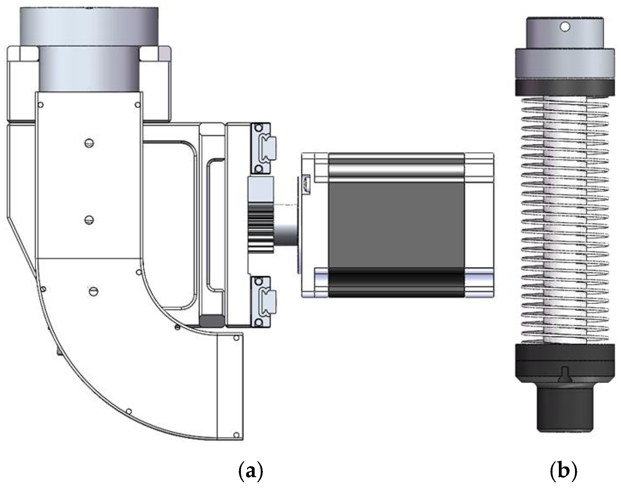
3.2. Propulsion Mechanism Analysis

This section presents the mechanical modeling and analysis of the propulsion mechanism for the robot’s flexible arm, focusing on the force characteristics of the cam–concave wheel structure during axial advancement and its implications for motor selection. A series of models describing the distribution of normal pressure, propulsion force, and torque are established to guide the parameter design of the propulsion system. As illustrated in Figure 3, the propulsion mechanism employs two sets of concave and cam wheels to clamp the flexible tube and achieve axial feeding. Under the preload exerted by compression springs, a contact area is formed between the wheels and the tube, generating normal pressure. The resulting frictional force enables the forward motion of the flexible tube within the pipeline.
First, based on contact mechanics between the wheels and the tube, let the preload be denoted as F p , the elastic recovery force of the flexible tube as F e , and the contact area as A c . The normal pressure, p , exerted between the wheel and the tube can then be expressed as follows:
p = F p + F e A c
Considering the friction-based propulsion mechanism, the propulsion force generated per cycle can be calculated as the product of the contact normal pressure and the friction coefficient, μ :
F p u s h = μ × ( F p + F e )
According to the structural configuration, the required output torque of the motor is determined by the radius of the driving wheel, R c (approximately 40 mm), and the propulsion force, F p u s h . Taking into account the transmission efficiency, η , and the safety factor, S , the motor torque requirement can be expressed as follows:
T m = F p u s h × R c × S η
Furthermore, to synchronize the cleaning rhythm with the brush head’s motion, a linear relationship exists between the rotational speed of the wheel set, n , and the axial feeding speed of the flexible tube, V p , which can be mathematically expressed as follows:
V p = n × π × D c
where D c represents the pitch diameter of the wheel set, approximately 17 mm. The friction coefficient, μ , is empirically set to 0.5, based on the typical dynamic friction between rubber and silicone. The preload force, F p , and the elastic recovery force, F e , are estimated through experimental loading tests. The transmission efficiency, η , is set to 0.85, and the safety factor, S , is defined as 1.5.

3.3. Alignment Mechanism Analysis

This section analyzes the motion principle and force characteristics of the robot’s alignment mechanism, with a particular focus on the gear–rack system used for vertical movement. The analysis considers external loads, frictional resistance, and inertial forces that must be overcome during operation. Based on this, the required output torque for the driving motor is derived to support component selection and control strategy development. As illustrated in Figure 5, the alignment mechanism employs a gear–rack structure to vertically adjust the position of the cleaning-brush head. The motor drives the gear to rotate, thereby enabling linear upward or downward motion of the rack. During this motion, several mechanical factors must be considered, including guide rail friction, the gravitational load of the brush assembly, and inertial forces during acceleration and deceleration. The total driving force required for rack motion can be expressed as follows:
F r = F l + μ × N + m × a
where F r represents the total driving force required for rack movement; and F l denotes the effective vertical load of the cleaning-brush assembly and its supporting structure, determined by their mass and gravitational force. The coefficient of sliding friction between the guide rail and the moving assembly is μ , with a typical value of 0.1 for precision linear guides. The normal force, N , acting on the guide rail is approximately equal to the gravitational force of the moving components. The mass of the rack and associated moving parts is denoted by m , and a is the maximum designed acceleration, set to 0.2 m/s2 in this study.
To overcome the resultant force, F r , the gear motor must provide a corresponding output torque, T m . Assuming the pitch radius of the gear is R , and considering the transmission efficiency ( η ) and a safety factor ( S ), the required torque is given by the following:
T m = F r × R × S η
In this system, a standard gear model, VNF31-1.0-20, is employed, with a module of m = 1.0 and number of teeth of z = 20 . According to the pitch diameter formula, D = m × z , the pitch diameter is calculated to be 20 mm, corresponding to a pitch radius of R = 10 mm. The transmission efficiency, η , accounting for gear meshing and guide rail friction, is set to 0.85. The safety factor, S , considering load fluctuations and extreme working conditions, is specified as 1.5.

4. Control System Design

This section focuses on the intelligent and automated control of the pipeline-cleaning robot, providing a systematic overview of the overall control architecture and functional implementation. The content includes the design of the control system architecture, hardware platform composition, software workflow, and the collaborative mechanism between image processing and control algorithms. Through deep integration of hardware and software, a control system with high stability, real-time responsiveness, and scalability is established, providing a solid foundation for the robot to efficiently perform cleaning tasks.

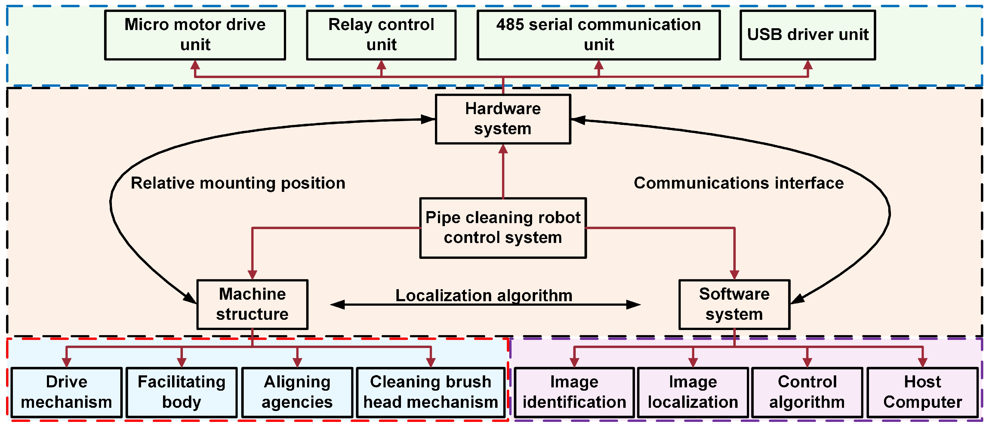
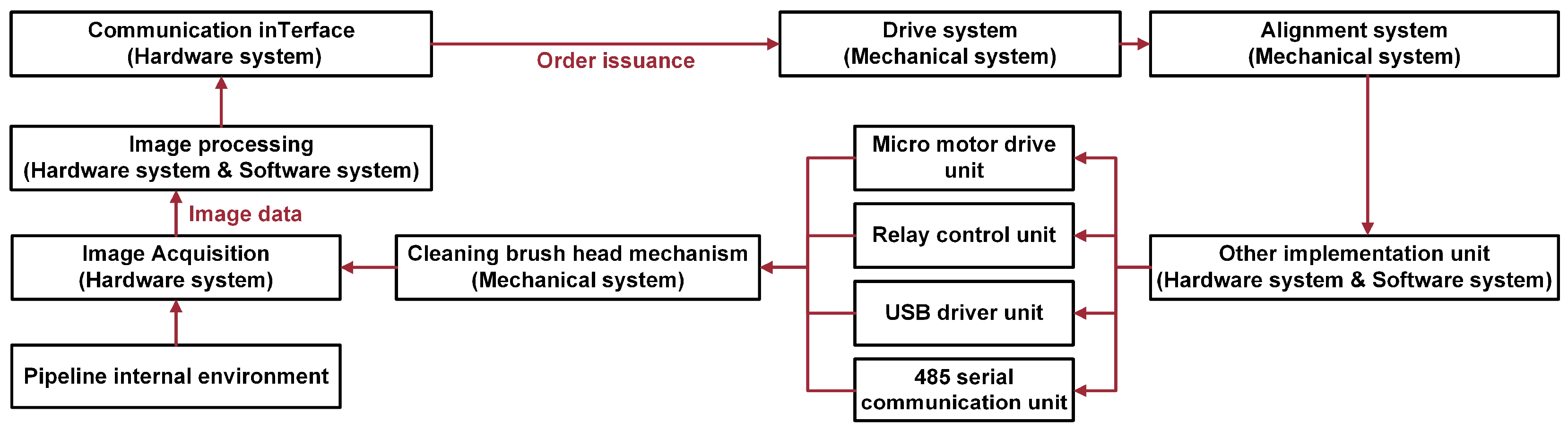
4.1. Overall Design of the Control System

To enable intelligent control and coordinated operation of multiple modules in the pipeline-cleaning robot, this section presents the overall architecture and functional allocation of the control system. The system integrates several key components, including image recognition, control algorithms, and actuator commands, with a co-designed hardware–software framework to ensure both execution accuracy and real-time performance. In industrial applications, system stability and ease of use are of paramount importance. Therefore, our design emphasizes reliability, real-time responsiveness, and user-friendliness. Based on these requirements and tailored to our specific application scenario, we have developed a dedicated control system for pipeline-cleaning tasks. A hierarchical and modular control strategy is adopted to achieve unified coordination and efficient control of all functional modules. As illustrated in Figure 8, the overall system comprises three main subsystems—hardware, software, and mechanical structure—which collectively form a complete perception–decision–execution loop.
The hardware subsystem is based on RS485 serial communication and GPIO control, enabling stable operation of low-level actuators such as miniature motors and relays. The software subsystem integrates modules for image recognition, image-based localization, and control algorithms, allowing real-time analysis of acquired visual data to extract the robot’s relative pose and generate task-dependent control commands accordingly. The mechanical subsystem comprises the driving unit, alignment mechanism, pushing module, and cleaning-brush assembly. These components serve as the final execution units of the control system, responsible for implementing the robot’s mobility, positioning, propulsion, and cleaning tasks.
During system operation, the onboard camera continuously captures internal pipeline images, which are processed by the software subsystem for image recognition and localization. Based on the analysis, the control module generates corresponding action commands, which are transmitted to the hardware system via communication interfaces to drive the actuators for cleaning execution. This architecture employs a typical closed-loop control strategy, utilizing visual feedback to enable real-time adjustment, thereby enhancing control accuracy and execution reliability. To ensure the system’s stability and robustness, the following design strategies are implemented:
  • Modular control architecture with decoupled subsystems improves fault tolerance;
  • Vision-based feedback dynamically corrects robot drift and localization errors inside the pipe;
  • Independent and redundant circuit layouts for driving and control, including overload protection and physical limit switches;
  • A state recognition and task-switching mechanism is embedded in the control logic to prevent malfunctions caused by abnormal data or environmental interference.
Through tight integration of software, hardware, and mechanical structures, the proposed robot system achieves stable and reliable autonomous cleaning in complex heat-exchanger pipelines with strong environmental adaptability.
In addition to the mechanical design described earlier, the control system also comprises the hardware and software subsystems. In the hardware subsystem, the central processing unit coordinates the execution of specific commands across modules based on task demands. In the software subsystem, image data collected by the hardware system are analyzed in real time using appropriate image processing techniques. The processed results are then combined with control algorithms to issue execution instructions to the hardware layer.
As shown in Figure 9, the control system initiates its operation once the pipeline-cleaning robot is deployed into the primary pipeline, and working conditions are satisfied. The hardware subsystem first captures internal pipeline images, which are then processed collaboratively by the hardware and software systems to extract task-relevant features. Based on the processed visual data and predefined control logic, corresponding motion commands are generated and transmitted through communication interfaces to the actuator modules within the mechanical system. The drive system executes locomotion tasks accordingly, while the alignment system adjusts the cleaning head vertically to reach the intended position. Once aligned, auxiliary components are activated, and the cleaning brush performs the cleaning operation. This procedure is repeated iteratively to complete all cleaning segments. To further clarify the hardware-level mapping of the modular architecture illustrated in Figure 8, the USB camera is used for image acquisition and connected to the SoC unit (e.g., RK3588), which handles real-time image processing and control algorithm execution. Control commands are issued via GPIO, UART, or EMAC interfaces to peripheral components such as micro-motors and relay modules that drive the cleaning head and locomotion unit. All commands are transmitted via the RS485 interface to the central controller, enabling precise motion coordination and task execution across subsystems.

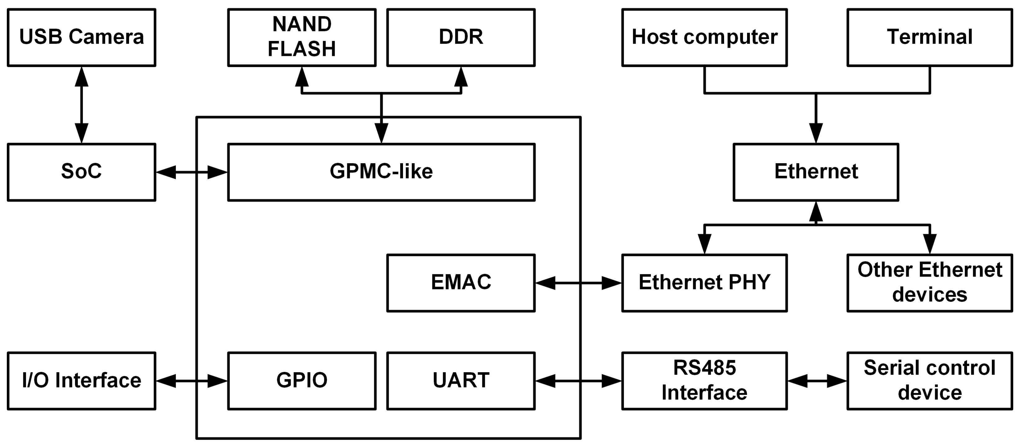
4.2. Hardware Design of the Control System

This section systematically presents the composition, functional division, and interconnections of each hardware module within the control system. Centered on a high-performance SoC (RK3588), the system establishes an integrated, closed-loop control architecture that supports image acquisition, data processing, control command generation, and actuator coordination. As illustrated in Figure 10, the control system comprises several core hardware modules: image acquisition, image processing, data storage, communication interface, serial control, and Ethernet drive modules. Among them, the serial control module is connected to miniature motor drivers and relay units, which are responsible for actuating the key components involved in the cleaning process of the robot.
Image acquisition is carried out using a high-definition USB camera, which captures visual data and transmits it to the SoC for preprocessing, object recognition, and target extraction. The processed results are sent via the UART interface to RS485-compatible motor drivers, enabling precise control of the robot’s drive and alignment modules. Simultaneously, the brush head motor is directly controlled through GPIO interfaces, while a relay module manages power switching and control of the water pump. All control tasks are centrally scheduled and executed by the SoC, which also communicates with the host terminal via the EMAC interface for command transmission and data exchange. To improve the interpretability of the control architecture shown in Figure 9 and Figure 10, this paper provides a detailed mapping between the software and hardware layers, along with the corresponding system-level modeling approach. The entire control system adopts a staged “perception–decision–execution” closed-loop strategy, establishing a clear control path across the hardware execution layer, image analysis layer, and decision-making layer.
From the perspective of control strategy, a state-event-driven task management mechanism is implemented, dividing the control process into five sequential stages: image acquisition, target positioning, pipe alignment, cleaning execution, and status feedback. Each stage incorporates logic for state verification to ensure the orderly completion of tasks, thereby minimizing operational errors or logic conflicts. Control commands are dynamically generated based on the results of image analysis and actuator feedback, ensuring accurate positioning and stable operation of the robot within complex heat-exchanger pipelines. This process is orchestrated by a main state machine in the software control layer, which ensures consistency and real-time coordination across modules.

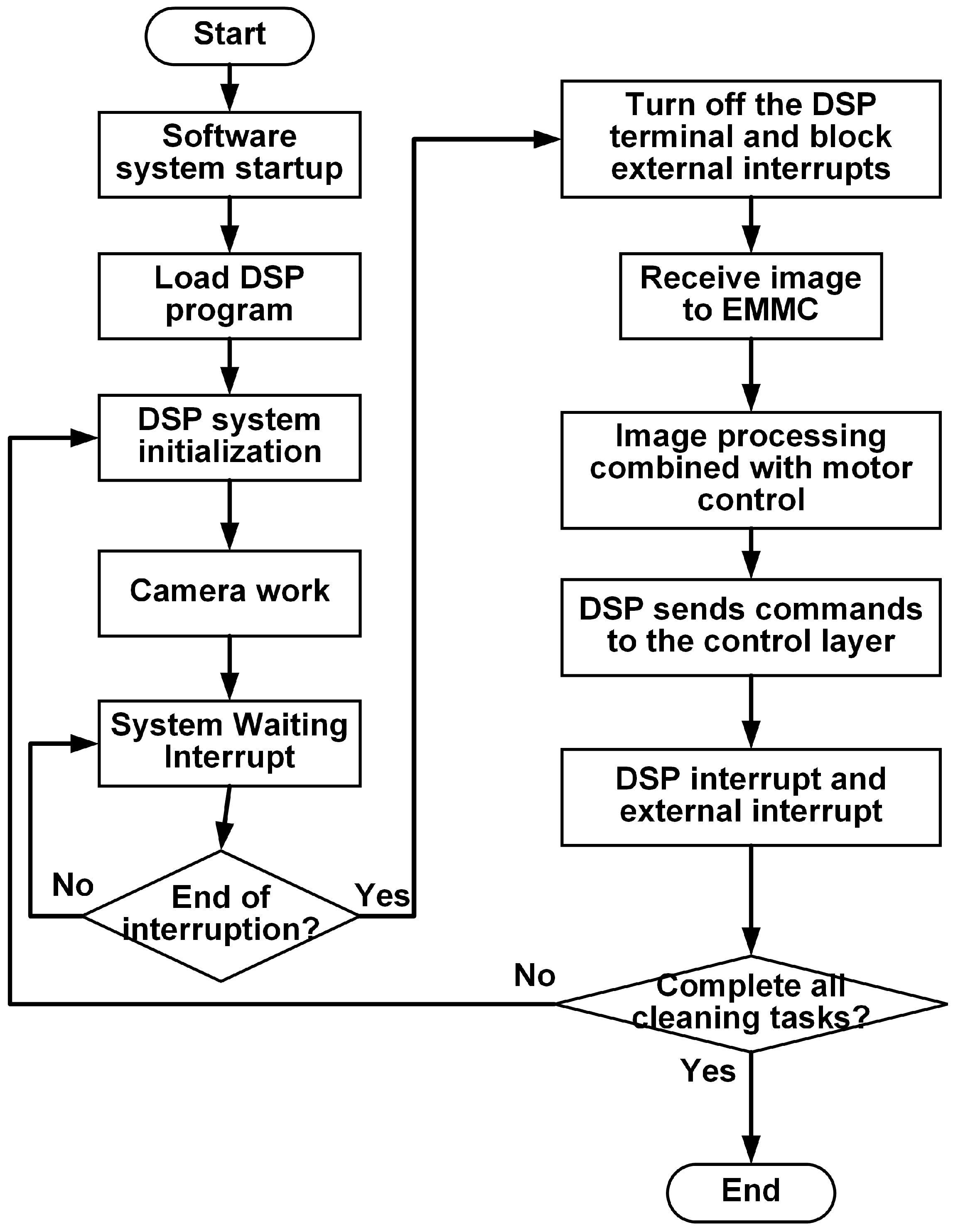
4.3. Software Design of the Control System

To enhance the real-time performance, operational stability, and maintainability of the pipeline-cleaning robot system, a modular software architecture and optimized control workflow were implemented. The system follows a closed-loop “perception–decision–execution” framework, with clearly decoupled functional modules to facilitate future maintenance and upgrades. As illustrated in Figure 11, the software control process consists of six primary stages: user program loading, system initialization, interrupt handling, image processing, control command generation, and task execution. These stages form a periodic control loop that ensures the stable and orderly execution of the cleaning operations.
At the initial stage of system operation, the main control chip automatically loads the user program and completes peripheral device initialization. Subsequently, the USB camera activates the image acquisition module and enters an interrupt listening state to await image data capture. When the image acquisition interrupt is triggered, the system immediately enters the interrupt service routine, during which external interrupts and DSP-level interrupts are disabled to ensure data integrity. The acquired image data are temporarily stored in the EMMC and passed to the image processing thread for preprocessing, feature extraction, and target localization.
The recognition results are then forwarded to the control algorithm module, which generates specific control commands based on system state and task requirements. These commands are transmitted via UART or GPIO interfaces to the corresponding actuators (e.g., drive motors, alignment mechanisms, and cleaning modules) to execute the cleaning task in a sequential manner. The entire control process is governed by a state-machine logic, where each node represents a distinct task stage (e.g., image acquisition, recognition, alignment, cleaning, and feedback). Transitions between states are triggered by conditional decision functions, ensuring both real-time scheduling and logical consistency. Interrupt signals and actuator feedback jointly constitute the sensory input of the software system, driving state transitions and maintaining the completeness and robustness of the closed-loop control framework.
To enhance alignment accuracy during sub-pipe-cleaning tasks, an image-guided brush-head calibration algorithm is implemented based on dual-channel PID control. The algorithm applies Hough transform and geometric feature extraction to determine the center coordinates of both the brush head and the sub-pipe opening. The deviation is computed and used to output correction commands in horizontal and vertical directions to guide precise alignment (see Algorithm 1 and Table 1 for details). The image processing pipeline comprises four key stages:
(1)
Image preprocessing: Grayscale conversion and bilateral filtering are applied to reduce noise while preserving edge features;
(2)
Feature extraction: Canny edge detection is performed, followed by morphological operations to enhance structural boundaries;
(3)
Geometric localization: Hough circle detection is employed to extract the centers of the brush head and the target sub-pipe for position recognition;
(4)
Deviation evaluation and control: The composite deviation Δ = Δ x 2 + Δ y 2 is calculated from the center offset Δ x , Δ y and compared with a threshold, ϵ . If Δ < ϵ , the system proceeds to the cleaning phase; otherwise, dual-channel PID controllers output horizontal and vertical correction commands iteratively.
Algorithm 1 Visual-Guided Alignment Algorithm with Closed-Loop Control
Input:
  Initial pipeline image I 0
  Alignment threshold ϵ
  Maximum iterations N m a x
Output:
  Motor control sequence C o u t
1:  Initialize: k 0 ,   Δ ,    C o u t  
2:  while ( Δ > ϵ ) and ( k < N m a x ) do
3:   Step 1: Image Processing
4:   Detect pipe center x p , y p
5:   Detect brush head center x b , y b
6:   Calculate deviations: Δ x     x p x b ,   Δ y     y p y b
7:   Compute total deviation: Δ     Δ x 2 + Δ y 2
8:   Step 2: Horizontal Alignment
9:   if Δ x > ϵ then
10:    Horizontal control u x     P I D ( Δ X )
11:    if Δ x > ϵ then
12:    C o u t   C o u t     { H o r i z o n t a l   m o t o r   f o r w a r d }
13:    else
14:    C o u t   C o u t     { H o r i z o n t a l   m o t o r   r e v e r s e }
15:    end if
16:   end if
17:   Step 3: Vertical Alignment
18:   if Δ y > ϵ then
19:    Horizontal control u y     P I D ( Δ y )
20:    if Δ y > ϵ then
21:    C o u t   C o u t     { V e r t i c a l   m o t o r   f o r w a r d }
22:    else
23:    C o u t   C o u t     { V e r t i c a l   m o t o r   r e v e r s e }
24:    end if
25:   end if
26:   Update image: I 0     I m a g e C a p t u r e ( )
27:   k     k + 1
28: end while
29: if Δ ϵ then
30:   C o u t     C o u t     { A l i g n m e n t   c o m p l e t e d }
31: else
32:   C o u t     C o u t     { T i m e o u t   a l e r t }
33:   Error recovery starts
34:   Reset actuators to default state
35:   Log current position and trigger fallback protocol
36:   Notify operator or retry alignment in next cycle
37: end if
A maximum number of iterations, N m a x , is set to prevent infinite loops. If alignment fails to converge within N _ { m a x } iterations, a fault-tolerant procedure is triggered, issuing a “timeout alert” and reporting the exception to the host computer. The system then either awaits manual intervention or reverts to the previous state to retry the task, thereby improving the robustness and fault tolerance of the visual servo mechanism.

5. Experimental Results and Discussion

This section presents the construction of the robotic prototype and experimental platform to verify the functionality and evaluate the performance of the proposed pipeline-cleaning robot. The experiments focus on validating the robot’s mobility within the main pipe, assessing its automatic alignment and cleaning effectiveness within sub-pipes, and testing the system’s response based on image processing feedback. Quantitative metrics, such as switching time and results from multiple repeated trials, are used to comprehensively evaluate the robot’s performance in terms of motion stability, cleaning efficiency, and the effectiveness of the control strategy.
As shown in Figure 12, the overall dimensions of the robotic prototype are 703 mm × 280 mm × 250 mm, with a total mass of approximately 25 kg. Figure 12a,b present the top view and front view of the robot, respectively, both based on the same structural configuration. These views illustrate the spatial distribution and frontal profile of the robotic structure. Except for the cleaning-brush head, all mechanical components are assembled using bolted connections to facilitate easy assembly and maintenance. To support functional validation, a representative testbed was constructed by fabricating simulated heat-exchanger main and sub-pipe structures, as shown in Figure 13. This platform provides a realistic cleaning environment to evaluate the structural adaptability of the robot and the stability of the control logic.
In addition, prior to the experiments, the robot was manually positioned at the front end of the pipeline. A low-pressure water flow (approximately 0.2 MPa, simulating the pressure level of a typical household spray gun) was applied to emulate the cleaning environment and assess the structural integrity and water resistance of the system. The sub-pipe inlet has an approximate diameter of 34 mm, while the main pipe has an inner diameter of 275 mm and an overall length of 2 m. To verify the system’s operational consistency and reliability under repeated conditions, each pipe-switching experiment was conducted three times under identical settings, with the execution time recorded for each trial.

5.1. Simulated Mobility Experiment for the Primary Pipeline to Be Cleaned

This experiment focused on evaluating the robot’s stable mobility within the main pipe. Prior to testing, the drive system remained in its natural state, with the wheel assemblies uncompressed and the robot’s outer diameter slightly exceeding that of the simulated main pipe. Upon insertion into the pipeline, the passive diameter-adjusting mechanism automatically compressed the springs to achieve wall-conforming fixation (Figure 14). This design ensures positional stability even in the absence of control signals, effectively preventing slippage or unintended rolling.
After activation, the robot can be operated via the host computer in either manual or automatic mode. Bidirectional movement is achieved through a high-torque drive motor in conjunction with a cross-configured wheel assembly. The experimental demonstration includes both forward and reverse operations (Figure 15). It is worth noting that to simulate realistic cleaning conditions, a low-pressure water environment—equivalent to that of a household spray gun—was applied during testing. Under these conditions, the robot maintained stable motion and was not affected by water flow disturbances, thus validating the robustness of the system during cleaning tasks.

5.2. Simulated Cleaning Experiment for the Secondary Pipeline

This section evaluates the robot’s capability to perform image-based recognition, alignment, and flexible arm propulsion under autonomous cleaning mode. Prior to cleaning, the robot was manually navigated to a position near the target sub-pipe. Subsequently, the system switched to automatic mode, wherein the onboard camera identified the sub-pipe inlet and triggered the alignment mechanism accordingly. As illustrated in Figure 16, a complete cleaning cycle performed by the robot includes the following sequential stages: image acquisition → interrupt trigger → visual processing → control command execution → alignment operation → cleaning propulsion. The corresponding program logic and algorithmic structure are detailed in Figure 11 and the accompanying pseudocode.
It is worth noting that although the current system relies on a miniature camera for alignment and recognition, the image processing algorithm has been functionally validated under clear water conditions. The system integrates image enhancement and filtering modules to mitigate the impact of mild visibility degradation. However, in environments with severe turbidity or sediment accumulation, the performance of visual recognition may be significantly compromised. To address this issue, future work will explore the integration of multi-modal sensing technologies—such as infrared imaging or ultrasonic assistance—to enhance system robustness and adaptability in complex operating conditions. To evaluate the system’s processing efficiency and cleaning precision, a multi-round switching experiment was conducted on sub-pipes No. 2 through No. 6. Each switching cycle encompassed the full procedure of image acquisition, alignment, and flexible arm advancement. The rotational speeds of both driving and pushing motors were uniformly set to 10 rpm, and the time consumption for each switching operation is summarized in Table 2. It should be emphasized that the current experiment primarily focused on validating the robot’s mechanical stability, task repeatability, and control process integrity. No actual industrial contaminants or standardized pollutant models were introduced during testing. As a result, the evaluation of cleaning performance was based on indirect indicators such as visual inspection and switching time, without quantitative metrics like residual contamination levels or surface coverage rate. This limitation is explicitly acknowledged in this section and will be addressed in future research. In subsequent studies, a test pipeline embedded with standardized contaminants will be constructed. Quantitative evaluation protocols will be established by incorporating residual image comparison and pre-/post-cleaning mass measurement of the brush head. These efforts aim to build a robust framework for evaluating cleaning effectiveness under realistic and challenging conditions, thereby improving the system’s engineering applicability and academic credibility.
Experimental results demonstrate that the system maintained a response time of less than 30 s for all sub-pipe switching tasks, indicating that the proposed image recognition and control strategy performs with high efficiency and stability under practical operating conditions. To provide a more comprehensive assessment of the system’s performance, a comparative analysis was conducted between the proposed robot and representative commercial pipeline-cleaning solutions, as well as related designs reported in the literature. For instance, the Hydra system developed by Mourik [33] and the automated cleaning robot from Idrojet [34] are widely employed in high-pressure cleaning operations for large-scale heat exchangers. While these systems exhibit strong cleaning capabilities and environmental adaptability, they typically rely on external hydraulic or pneumatic power sources, resulting in large physical dimensions that are unsuitable for confined primary pipe environments.
In contrast, the robot proposed in this study features a compact form factor (703 mm × 280 mm × 250 mm) and supports autonomous switching between multiple sub-pipes within the primary pipeline. The system integrates vision-guided control, a flexible cam–concave wheel propulsion mechanism, and a rapid alignment module. Under simulated heat-exchanger conditions, it completed a full cleaning cycle in less than 30 s. With its portability, structural adaptability, and high level of automation, the proposed system effectively bridges the gap between large-scale industrial cleaning equipment and manual tools, offering significant potential for practical engineering applications.

6. Conclusions

This study presents a modular robotic system specifically designed for pipe-cleaning tasks in confined spaces. The system comprises a driving module, pushing module, alignment module, and cleaning-brush unit. The main body of the robot measures 703 mm × 280 mm × 250 mm and weighs approximately 25 kg. By adopting a cyclical cleaning workflow and incorporating a flexible mechanical arm, the system effectively performs autonomous inner-wall cleaning of sub-pipes while simplifying task programming complexity. The robot employs a dual-wheel cross-drive configuration, where the master and slave wheels are arranged in an intersecting layout to reduce torque requirements and enhance motion stability within the pipe. The pushing mechanism utilizes cam–concave wheel compression to propel the flexible arm, providing sufficient force for the brush head to penetrate into the sub-pipe. The alignment unit adopts a gear–rack transmission structure to enable precise vertical positioning of the brush head. All components are assembled via bolted connections, ensuring modular disassembly and ease of maintenance.
Experimental results demonstrate that the proposed robot completes a full pipe-switching cycle in under 30 s when operating in autonomous mode, confirming the system’s feasibility in terms of control efficiency and cleaning effectiveness. The robot integrates mechanical design, hardware components, and software modules into a highly cohesive system, exhibiting strong automation capability and adaptability to complex environments. This makes it a promising solution for intelligent cleaning tasks in narrow heat-exchanger pipelines.
The robot’s main body is constructed from aluminum alloy, offering a favorable balance of structural strength and chemical corrosion resistance, while ensuring non-destructive cleaning of the pipe interior. It is worth noting that during the cleaning process, debris dislodged by brush vibrations and high-pressure water jets may accumulate locally, potentially leading to mechanical blockage or impaired propulsion. Although such interference was not observed during testing, future iterations will consider integrating mesh filtration structures or sediment detection mechanisms to enhance system robustness and continuous operational capability in high-contamination environments.
Future research will focus on the following four directions: First, to address mechanical fatigue and load sensitivity during long-term operation, the overall structural layout will be further optimized by incorporating lightweight materials and compliant mechanisms, thereby improving durability and reducing the overall system mass. Second, the distributed control hardware will be integrated into the robot body to eliminate issues related to excessive cable length, such as signal attenuation, wiring complexity, and deployment constraints, ultimately enhancing system mobility and engineering adaptability. Third, in response to potential brush-head obstructions caused by debris accumulation during high-pressure cleaning, future versions will incorporate replaceable mesh filters and localized sediment monitoring mechanisms to ensure uninterrupted cleaning and improve system robustness in heavily contaminated environments. Finally, a virtual simulation-based evaluation platform will be developed to assess the robot’s performance under extreme conditions—such as sharp bends, diameter transitions, and blockages—and varying cleaning parameters (e.g., water pressure and vibration intensity). This platform will serve as a pre-validation tool for structural optimization and control strategy development, accelerating the intelligent evolution of the system.

Author Contributions

Conceptualization, Q.L., G.W., and L.L.; methodology, Q.L. and Y.W.; software, C.L. and J.W.; validation, Q.L., G.W., and L.L.; formal analysis, G.W.; investigation, C.L. and J.T.; resources, J.T. and L.L.; data curation, C.L.; writing—original draft preparation, Q.L. and G.W.; writing—review and editing, Q.L., C.L., and J.T.; visualization, G.W and Y.W.; supervision, L.L. and J.W.; project administration, G.W.; funding acquisition, L.L., Y.W., and Q.L. All authors have read and agreed to the published version of the manuscript.

Funding

This research received no external funding.

Data Availability Statement

The original contributions presented in this study are included in the article. Further inquiries can be directed toward the corresponding author.

Conflicts of Interest

Authors Qianwen Liu, Guangfei Wang, Lijuan Li, and Yuxiang Wu were employed by the company China Nuclear Power Engineering Co., Ltd. The remaining authors declare that the research was conducted in the absence of any commercial or financial relationships that could be construed as a potential conflict of interest.

Abbreviations

The following abbreviations are used in this manuscript:
SoCSystem on Chip
UARTUniversal Asynchronous Receiver/Transmitter
GPIOGeneral-Purpose Input/Output
EMACEthernet Media Access Controller
DSPDigital Signal Processor

References

  1. Zhu, M.; Briot, S.; Chriette, A. Sensor-Based Design of a Delta Parallel Robot. Mechatronics 2022, 87, 102893. [Google Scholar] [CrossRef]
  2. Zhao, P.; Zhang, Y.; Guan, H.; Deng, X.; Chen, H. Design of a Single-Degree-of-Freedom Immersive Rehabilitation Device for Clustered Upper-Limb Motion. J. Mech. Robot. 2021, 13, 031006. [Google Scholar] [CrossRef]
  3. Zhu, M.; Huang, C.; Song, S.; Xu, S.; Gong, D. Vision-Admittance-Based Adaptive RBFNN Control with a SMC Robust Compensator for Collaborative Parallel Robots. J. Frankl. Inst. 2024, 361, 106538. [Google Scholar] [CrossRef]
  4. Huang, C.; Zhu, M.; Song, S.; Zhao, Y.; Jiang, J. Vision-Based Adaptive LT Sliding Mode Admittance Control for Collaborative Robots with Actuator Saturation. Robotica 2024, 42, 1986–2003. [Google Scholar] [CrossRef]
  5. Wang, Y.; Wang, J.; Zhou, Q.; Feng, S.; Wang, X. Mechanism Design and Mechanical Analysis of Pipeline Inspection Robot. Ind. Robot. Int. J. Robot. Res. Appl. 2025, 52, 137–143. [Google Scholar] [CrossRef]
  6. John, B.; Shafeek, M. Pipe Inspection Robots: A Review. In Proceedings of the IOP Conference Series: Materials Science and Engineering, Online, 9–13 May 2022; Volume 1272, p. 012016. [Google Scholar]
  7. Shao, L.; Wang, Y.; Guo, B.; Chen, X. A Review over State of the Art of In-Pipe Robot. In Proceedings of the 2015 IEEE Inter-national Conference on Mechatronics and Automation (ICMA), Beijing, China, 2–5 August 2015; pp. 2180–2185. [Google Scholar]
  8. Kahnamouei, J.T.; Moallem, M. A Comprehensive Review of In-Pipe Robots. Ocean Eng. 2023, 277, 114260. [Google Scholar] [CrossRef]
  9. Jang, H.; Kim, T.Y.; Lee, Y.C.; Kim, Y.S.; Kim, J.; Lee, H.Y.; Choi, H.R. A Review: Technological Trends and Development Direction of Pipeline Robot Systems. J. Intell. Robot. Syst. 2022, 105, 59. [Google Scholar] [CrossRef]
  10. Miyake, S.; Yoshida, K.; Sugano, S.; Kamezaki, M. Preliminary Design and Evaluation of a Ducted-Fan Type Pipeline Robot. ROBOMECH J. 2024, 11, 7. [Google Scholar] [CrossRef]
  11. Shen, Z.; Xie, M.; Song, Z.; Bao, D. Design and Performance Analysis of a Parallel Pipeline Robot. Electronics 2024, 13, 4848. [Google Scholar] [CrossRef]
  12. Zheng, T.; Wang, X.; Li, H.; Zhao, C.; Jiang, Z.; Huang, Q.; Ceccarelli, M. Design of a Robot for Inspecting the Multishape Pipeline Systems. IEEE/ASME Trans. Mechatron. 2022, 27, 4608–4618. [Google Scholar] [CrossRef]
  13. Song, S.; Zhao, M.; Gong, D.; Zhu, M. Convergence and Stability Analysis of Value Iteration Q-Learning under Non-Discounted Cost for Discrete-Time Optimal Control. Neurocomputing 2024, 606, 128370. [Google Scholar] [CrossRef]
  14. Song, S.; Gong, D.; Zhu, M.; Zhao, Y. Discrete-Time Optimal Control of State-Constrained Nonlinear Systems Using Approximate Dynamic Programming. Int. J. Robust Nonlinear Control 2025, 35, 858–871. [Google Scholar] [CrossRef]
  15. Xu, Y.; Wang, M.; Du, L.; Bao, S.; Hu, Z.; Yuan, J. Design of a Magnetic Hemispherical Wheeled Pipeline Robot. In Proceedings of the 2024 IEEE International Conference on Mechatronics and Automation (ICMA), Tianjin, China, 4 August 2024; pp. 1671–1676. [Google Scholar]
  16. Helan Vidhya, T.; Deepak, G.L.; Amruth, K.V.; Ponnarasan, D. WALL E: A Robotic Duct Cleaning System. In Proceedings of the 2024 International Conference on Advances in Computing, Communication and Applied Informatics (ACCAI), Chennai, India, 9 May 2024; pp. 1–7. [Google Scholar]
  17. Momma, Y.; Hitomi, T.; Ito, F.; Nakamura, T. Square Duct Cleaning Machine Using a Multistage Planetary Gear Mechanism for Removing Grease. IEEE Access 2025, 13, 1962–1973. [Google Scholar] [CrossRef]
  18. Tanihira, H.; Tanaka, M. Motion Design of a Pipe Cleaning Snake Robot with a Long Brush. Adv. Robot. 2024, 38, 863–879. [Google Scholar] [CrossRef]
  19. Lee, K.; Kim, J.; Kim, K.; Park, J. Development of a Rotation Swab Pig Method for Cleaning Water Pipes. J. Korean Geosynth. Soc. 2024, 23, 63–75. [Google Scholar] [CrossRef]
  20. Liu, X.-Y.; Yang, J.-D.; Zhang, Y.; Zhang, X.-J.; Liu, H.-Y.; Duan, X.-H. Research on Automatic Pipe Cleaning Technology for Natural Gas Medium and Low Pressure Pipelines. J. Phys. Conf. Ser. 2024, 2834, 012153. [Google Scholar] [CrossRef]
  21. Tang, C.; Du, B.; Jiang, S.; Shao, Q.; Dong, X.; Liu, X.-J.; Zhao, H. A Pipeline Inspection Robot for Navigating Tubular Environments in the Sub-Centimeter Scale. Sci. Robot. 2022, 7, eabm8597. [Google Scholar] [CrossRef]
  22. Li, X.; Liu, L.; Huang, P.; Li, B.; Xing, Y.; Wu, Z. A Highly Adaptable Soft Pipeline Robot for Climbing Outside Millimeter-Sized Pipelines. Nano Energy 2025, 134, 110566. [Google Scholar] [CrossRef]
  23. Roh, S.-G.; Choi, H.R. Differential-Drive in-Pipe Robot for Moving inside Urban Gas Pipelines. IEEE Trans. Robot. 2005, 21, 1–17. [Google Scholar] [CrossRef]
  24. Kazeminasab, S.; Sadeghi, N.; Janfaza, V.; Razavi, M.; Ziyadidegan, S.; Banks, M.K. Localization, Mapping, Navigation, and Inspection Methods in In-Pipe Robots: A Review. IEEE Access 2021, 9, 162035–162058. [Google Scholar] [CrossRef]
  25. Li, Y.; Huang, X. Oil and Gas Pipeline Robot Localization Techniques: A Review. Proc. Inst. Mech. Eng. Part C: J. Mech. Eng. Sci. 2024, 238, 11049–11067. [Google Scholar] [CrossRef]
  26. Wang, W.; Gao, Z. A Variable Diameter Climbing Gait Design for a Snake Robot Based on the Bezier Curve. Int. J. Control Autom. Syst. 2024, 22, 3753–3761. [Google Scholar] [CrossRef]
  27. Han, L.; Ding, F.; Zhao, L.; Li, P.; Li, C.; Liu, M.; Ren, L.; Li, Y. Design and Motion Analysis of a Coal Mine Robot with Variable Wheel Diameter. Sci. Rep. 2025, 15, 6497. [Google Scholar] [CrossRef]
  28. Choi, H.R.; Roh, S. In-Pipe Robot with Active Steering Capability for Moving inside of Pipelines. In Bioinspiration and Robotics Walking and Climbing Robots; Intech Open Access Publisher: London, UK, 2007. [Google Scholar]
  29. Galajdová, A.; Virgala, I.; Kelemen, M.; Miková, L.; Lipták, T.; Kelemenová, T. Influence of Pipe Geometric Deviation on Bristled In-Pipe Mobile Robot Locomotion. Int. J. Adv. Robot. Syst. 2018, 15, 1729881418775808. [Google Scholar] [CrossRef]
  30. Rusu, C.; Tatar, M.O. Adapting Mechanisms for In-Pipe Inspection Robots: A Review. Appl. Sci. 2022, 12, 6191. [Google Scholar] [CrossRef]
  31. Zhang, Y.; Yan, G. In-Pipe Inspection Robot with Active Pipe-Diameter Adaptability and Automatic Tractive Force Adjusting. Mech. Mach. Theory 2007, 42, 1618–1631. [Google Scholar] [CrossRef]
  32. Jiang, J.; Zhang, F.; Wang, L. Soft Modular Pipe Robot Inspired by Earthworm for Adaptive Pipeline Internal Structure. Smart Mater. Struct. 2024, 33, 105019. [Google Scholar] [CrossRef]
  33. Mourik. Hydra Robotic Exchanger Cleaning Successful at Chemelot Site. Available online: https://www.mourik.com/news/hydra-robotic-exchanger-cleaning-successful-at-chemelot-site.html (accessed on 19 April 2025).
  34. Idrojet. Automatic Tube Bundle Cleaning System. Available online: https://www.idrojet.com/product/autojet-si-9305/ (accessed on 19 April 2025).
Figure 1. Pipe-cleaning robot.
Electronics 14 02321 g001
Figure 2. Schematic of the passive diameter-adjustment structure. It includes compression springs (), spring bases (), compression directions (), and roller–pipe contact surfaces ().
Electronics 14 02321 g002
Figure 3. Drive mechanisms: (a) first drive mechanism and (b) second drive mechanism.
Electronics 14 02321 g003
Figure 4. Sending organization.
Electronics 14 02321 g004
Figure 5. Aligning agencies: (a) subjects and (b) cleaning-brush-head mechanism.
Electronics 14 02321 g005
Figure 6. (a) Schematic diagram of the pipe-cleaning robot operating in four sequential phases. Red arrows indicate the cleaning-head movement and alignment direction. (b) Flowchart of the cleaning process, showing the control logic across each phase, including detection, alignment, propulsion, and evaluation stages.
Electronics 14 02321 g006
Figure 7. Cross-rotor configuration.
Electronics 14 02321 g007
Figure 8. Overall architecture of the pipe-cleaning robot control system. The system integrates software modules (image recognition and decision logic), hardware modules (microcontroller, motor and relay drivers, and communication interfaces), and the mechanical structure (drive unit, and alignment and cleaning mechanisms). Information flows from visual perception to decision-making and actuation, forming a real-time closed-loop control loop.
Electronics 14 02321 g008
Figure 9. Control system workflow and signal flow logic. The diagram illustrates the data and control flow across hardware and software subsystems, including image acquisition (USB camera), SoC-based processing and command generation, and actuation via RS485-controlled motor and relay units.
Electronics 14 02321 g009
Figure 10. Hardware architectures.
Electronics 14 02321 g010
Figure 11. Software system flowchart.
Electronics 14 02321 g011
Figure 12. Robot prototype views: (a) top view and (b) front view of the same robot prototype under identical configuration.
Electronics 14 02321 g012
Figure 13. Robot performance experiment pipeline.
Electronics 14 02321 g013
Figure 14. Before the robot is placed in the simulated pipe.
Electronics 14 02321 g014
Figure 15. Robot advances in cleaning the main pipe: (a) home position, and (b) forward and back.
Electronics 14 02321 g015
Figure 16. Pipeline switching process. (a) Pipe opening is not aligned. (b) Pipe ports are aligned.
Electronics 14 02321 g016
Table 1. Algorithm nomenclature.
SymbolDescriptionMathematical Definition
I 0 Initial imageRGB image matrix   R m × n × 3
ϵ Alignment thresholdPosition tolerance ϵ > 0
N m a x Max iterationsPositive integer
x p , y p Pipe centerDetected by Hough transform
x b , y b Brush head centerFeature matching coordinates
Δ x Horizontal deviation Δ x = x p x b
Δ y Vertical deviation Δ y = x y x y
Δ Total deviation Δ = Δ x 2 + Δ y 2
k Iteration counter k 0,1 , , N m a x
C o u t Control commandsSet of motor commands
PID( · )Control function u t = K p e t + K i e + K d d e d t
Table 2. Pipe switching-time experiment data.
Switching CaseGroup 1 (s)Group 2 (s)Group 3 (s)Mean (s)Std Dev (s)
Tube 2 → 315131614.671.53
Tube 3 → 414121112.331.53
Tube 4 → 521171718.332.31
Disclaimer/Publisher’s Note: The statements, opinions and data contained in all publications are solely those of the individual author(s) and contributor(s) and not of MDPI and/or the editor(s). MDPI and/or the editor(s) disclaim responsibility for any injury to people or property resulting from any ideas, methods, instructions or products referred to in the content.

