Article

Adaptive Control Strategy for the PI Parameters of Modular Multilevel Converters Based on Dual-Agent Deep Reinforcement Learning

1
School of Electrical & Information Engineering, Changsha University of Science and Technology, Changsha 410114, China
2
School of Physics & Electronic Science, Changsha University of Science and Technology, Changsha 410114, China
*
Author to whom correspondence should be addressed.
Electronics 2025, 14(11), 2270; https://doi.org/10.3390/electronics14112270
Submission received: 18 April 2025 / Revised: 21 May 2025 / Accepted: 23 May 2025 / Published: 31 May 2025
(This article belongs to the Section Power Electronics)

Abstract

:
As renewable energy sources are integrated into power grids on a large scale, modular multilevel converter-high voltage direct current (MMC-HVDC) systems face two significant challenges: traditional PI (proportional integral) controllers have limited dynamic regulation capabilities due to their fixed parameters, while improved PI controllers encounter implementation difficulties stemming from the complexity of their control strategies. This article proposes a dual-agent adaptive control framework based on the twin delayed deep deterministic policy gradient (TD3) algorithm. This framework facilitates the dynamic adjustment of PI parameters for both voltage and current dual-loop control and capacitor voltage balancing, utilizing a collaboratively optimized agent architecture without reliance on complex control logic or precise mathematical models. Simulation results demonstrate that, compared with fixed-parameter PI controllers, the proposed method significantly reduces DC voltage regulation time while achieving precise dynamic balance control of capacitor voltage and effective suppression of circulating current, thereby notably enhancing system stability and dynamic response characteristics. This approach offers new solutions for dynamic optimization control in MMC-HVDC systems.

1. Introduction

In the context of the global energy structure transitioning towards a high proportion of renewable energy, high voltage direct current (HVDC) transmission, characterized by its large capacity and long-distance capabilities, has emerged as a core solution for integrating renewable energy into the grid [1]. HVDC systems based on modular multilevel converters (MMC) have been widely deployed in offshore wind power and desert photovoltaic applications [2]. However, their dynamic control faces significant challenges. (1) The stochasticity and intermittency of renewable energy generation can lead to grid power imbalance, subsequently triggering zero-sequence circulating currents and DC voltage fluctuations, which render the operational states of MMC highly dynamic and complex [3]. (2) Conventional controllers fail to meet MMCs’ control requirements under diverse operating conditions [4]. (3) Both the topological structure and mathematical models of MMCs exhibit significant complexity [5]. These issues lead to a substantial increase in the complexity of MMC system control.
Researchers have developed a series of control methodologies specifically designed for the MMC to enhance its control effectiveness. From the perspective of the control hierarchy, these methodologies can be categorized into high-level control and low-level control. The high-level controller is mainly responsible for modulating external variables such as active power [6], reactive power [7], DC voltage [8,9], and AC voltage and frequency [10]. In contrast, the low-level controller focuses on regulating internal variables within the MMC, including the regulation of submodule capacitor voltage and energy balance [11], circulating current suppression [12], and arm energy balancing [13]. In summary, all these control strategies rely on accurate mathematical modeling of the MMC for targeted design and place stringent demands on the performance of the employed controllers.
To address the stringent control requirements of MMC, researchers have proposed a variety of controllers, including sliding mode controllers (SMCs), model predictive controllers, proportional-resonant (PR) controllers, reduced-order generalized integrators, and PI controllers [14]. Despite challenges such as complex parameter tuning and relatively slow dynamic response, the structural simplicity and strong robustness of PI controllers ensure their widespread use in various control strategies and practical engineering applications. Therefore, research on and improvement of PI controllers hold significant theoretical importance and practical value for enhancing system control precision and engineering reliability.
Compared with conventional proportional integral (PI) controllers, fuzzy PID controllers demonstrate enhanced transient performance with accelerated response characteristics and mitigated steady-state errors [15]. However, their reliance on predefined rules limits their dynamic regulation capabilities. Moreover, intelligent optimization algorithms, such as ant colony optimization [16], particle swarm optimization [17], water cycle algorithms [18], and genetic algorithms [19], have been applied to the real-time tuning of PI controller parameters, addressing the limitations of traditional static parameter adjustment methods. Nevertheless, when dealing with complex, strongly coupled system models, these algorithms may suffer from limited convergence rates, potentially compromising control performance. Another approach involves combining PI controllers with other control strategies to form hybrid controllers. For example, [20] integrates a PI controller with an SMC to enhance system stability; [21] combines a bang-bang funnel controller with a PI controller to improve fault ride-through capability; and [22] incorporates a PR controller with a PI controller to suppress circulating currents. However, the parameter settings in these hybrid controllers still heavily depend on empirical adjustments, which makes it challenging to achieve globally optimal control performance. Moreover, most hybrid control architectures feature fixed structures that are incapable of adaptively adjusting controller parameters based on operational states, thereby constraining their ability to satisfy dynamic demands under complex operating conditions.
In recent years, the rapid proliferation of renewable energy sources, such as photovoltaic and wind power [23], has significantly increased the complexity and uncertainty of power grid operating environments. To address this challenge effectively, artificial intelligence technologies, especially deep reinforcement learning (DRL), have become indispensable tools in power system control [24]. By leveraging its end-to-end environmental perception and adaptive policy optimization capabilities, DRL has demonstrated remarkable performance in various scenarios, including voltage regulation [25], load frequency control [26,27], and emergency control of power systems [28,29]. From the perspective of algorithm architecture evolution, the Deep Q-Network has shown notable proficiency in tasks with discrete action spaces [30]. However, it is unsuitable to meet the continuous control requirements of MMC. The Deep Deterministic Policy Gradient (DDPG) algorithm supports continuous control but faces challenges such as Q-value overestimation and a tendency to converge to local optima during practical applications [31]. The Twin Delayed Deep Deterministic Policy Gradient (TD3) algorithm addresses these limitations by incorporating a dual Q-network structure and delayed update mechanism, thereby enhancing convergence stability and learning efficiency [32]. Moreover, DRL includes other significant algorithms, such as proximal policy optimization [33] and soft actor-critic, each offering unique advantages across different application scenarios. Compared to traditional single-agent architectures, multi-agent DRL can more efficiently handle high-dimensional nonlinear systems like MMCs, which consist of strongly coupled submodules. This capability is achieved through distributed policy optimization and local-global reward coordination mechanisms [34].
To address the insufficient regulation capability of traditional controllers under complex MMC operating conditions, as well as the challenges of intricate design and heavy reliance on precise mathematical models, this article proposes a dual-agent adaptive PI control architecture based on the TD3 algorithm (DA-TD3). The core innovations are summarized as follows:
(1) A dual-agent framework incorporating a collaborative optimization mechanism is developed. Agent 1 specializes in generating PI control parameters for voltage and current dual-loop control, while Agent 2 focuses on tuning PI parameters for capacitor voltage balance control. Both agents share key state variables (DC voltage error) and utilize differentiated weight coefficients in their respective reward functions to ensure DC voltage stability. This design not only achieves a specialized division of labor in subsystem control but also reinforces the global constraint on the primary control objective (DC voltage stability) through hierarchical weighting and shared observations. By establishing collaborative strategies among agents, the trade-off between local optimization and global stability in multi-objective control scenarios is effectively addressed, leading to a notable improvement in the algorithm’s convergence speed.
(2) Leveraging the data-driven nature of the TD3 algorithm, the DA-TD3 architecture enables online adaptation to complex operating conditions through end-to-end autonomous learning. Moreover, this architecture overcomes the reliance on precise mathematical models inherent in traditional methods and avoids the limitations of manual parameter tuning based on empirical experience. Ultimately, the trained agents can detect real-time changes in operating conditions and generate continuously optimal PI controller parameters, thereby achieving rapid and stable control of the MMC system.
The remainder of this article is structured as follows. Section 2 describes the MMC topology and its fundamental control principles. Section 3 elaborates on the MMC control strategy based on the DA-TD3 algorithm. Section 4 validates the effectiveness of the proposed algorithm through simulation experiments. Section 5 summarizes the entire article.

2. Topology and Control Principles of MMCs

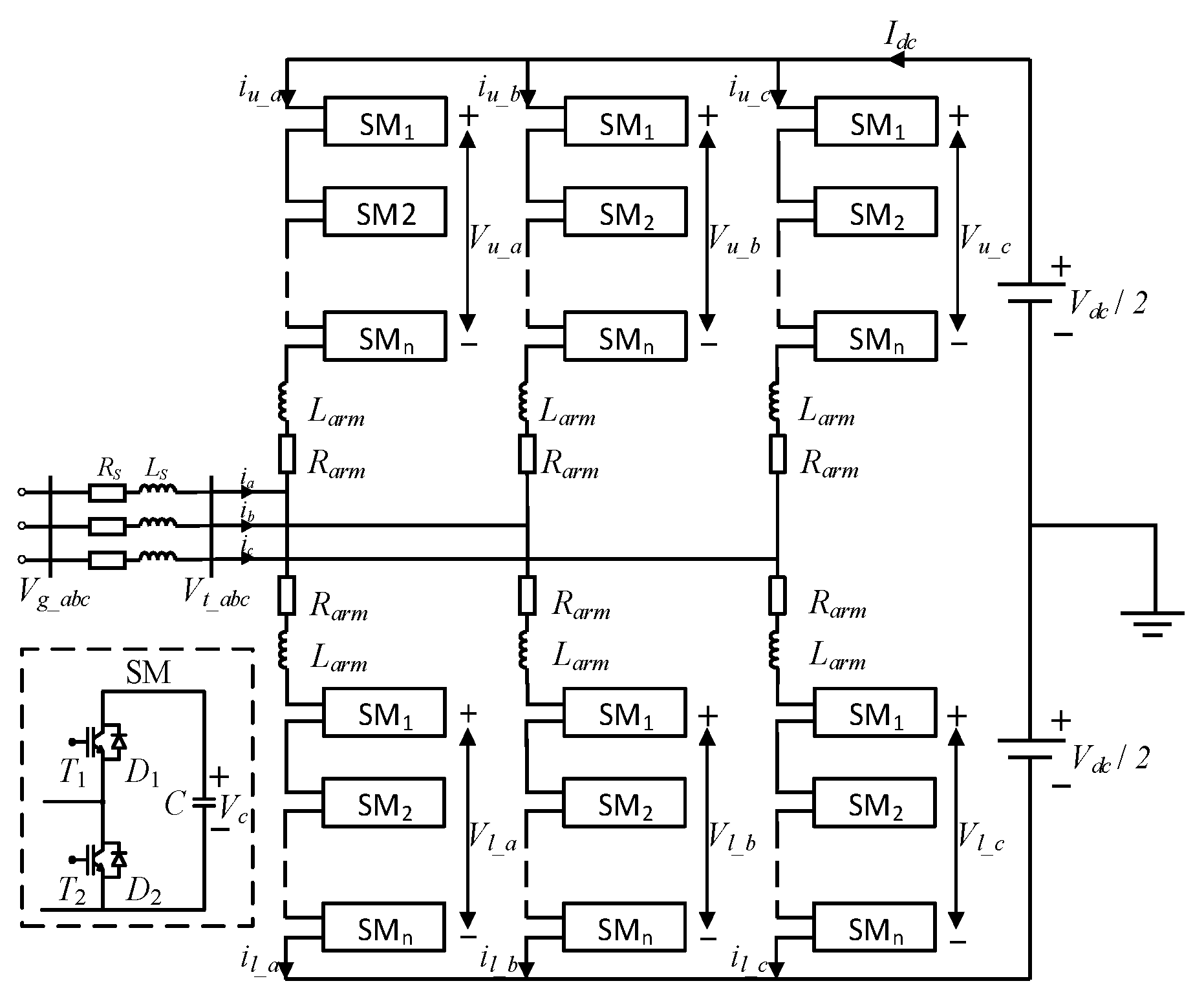
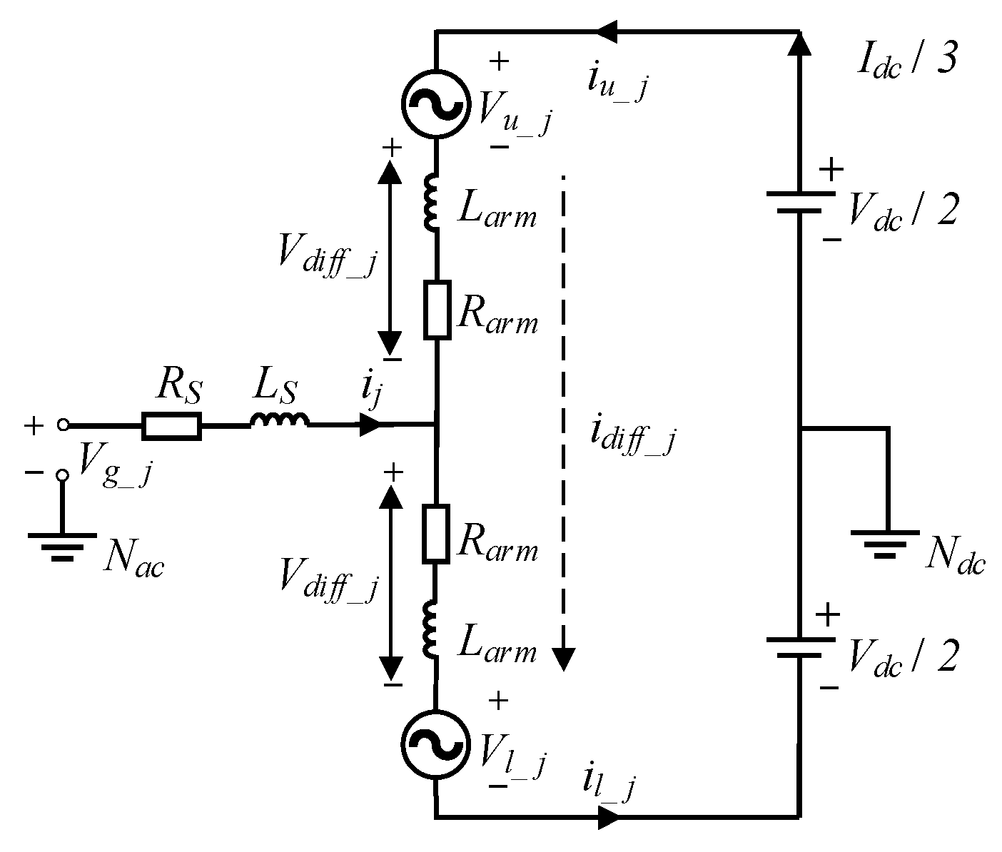
2.1. Topological Structure and Mathematical Modeling of MMCs

Figure 1 depicts the topology of a single-phase MMC, which comprises upper and lower arms. Each arm comprises N identical submodules (SM) connected in series. The submodules adopt a half-bridge structure, which includes two insulated gate bipolar transistors (T1/T2), two reverse-parallel diodes (D1/D2), and a submodule capacitor (C). By controlling the switching states of the IGBTs, the submodule can either output the capacitor voltage Vc or be bypassed. Furthermore, arm inductors Larm and resistors Rarm are incorporated to mitigate circulating currents and limit fault current transients.
The mathematical model of the three-phase MMC can be derived via single-phase analysis, leveraging the system’s symmetry. As shown in Figure 2, the equivalent circuit model of a single-phase MMC is presented. For each phase j (where j = a, b, c), the electrical potentials across the upper and lower arms are respectively designated by the symbolic representations Vu_j and Vl_j. The voltage drop across the arm impedance is denoted as Vdiff_j. The three-phase AC grid voltage, equivalent grid resistance, and equivalent grid inductance are represented by Vg_j, Rs, and Ls, respectively. The neutral points are Ndc (DC-side neutral) and Nac (AC-side grounded neutral).
The dynamic equations for the upper and lower arms can be formulated as follows:
V d c 2 V u _ j R a r m i u _ j L a r m d i u _ j d t + R s i j + L s d i j d t V g _ j = 0 V d c 2 + V l _ j + R a r m i l _ j + L a r m d i l _ j d t + R s i j + L s d i j d t V g _ j = 0
To achieve balanced three-phase power, the DC Idc is equally distributed across three phases, while the output current undergoes symmetrical division between the upper and lower arms. This current allocation principle leads to the following relationships for the arm currents:
i u _ j = I d c 3 + i d i f f _ j + i j 2 i l _ j = I d c 3 + i d i f f _ j i j 2
In Equation (2), idiff_j represents the circulating current that consists solely of the AC component. Therefore, the mathematical representation of circulating current (denoted as icir_j is derivable through the following analytical formulation:
i c i r _ j = i u _ j i j 2 = i l _ j + i j 2 i j = i u _ j i l _ j
By summing up the two equations presented in (1) and substituting the resultant expression into ij in (2), the external dynamic equation of the MMC can be systematically derived as follows:
L a r m + 2 L s d i j d t = R a r m + 2 R s i j + V u _ j V l _ j + 2 V g _ j
By subtracting the two equations in (1) and substituting the resultant expression into idiff_j in (2), the internal dynamic equation of the MMC can consequently be formulated as follows:
V d i f f _ j = L a r m d i d i f f _ j d t + R a r m i d i f f _ j + R a r m I d c 3 = V d c 2 V u _ j + V l _ j 2
Equations (4) and (5) collectively form the theoretical foundation of the MMC control strategy.

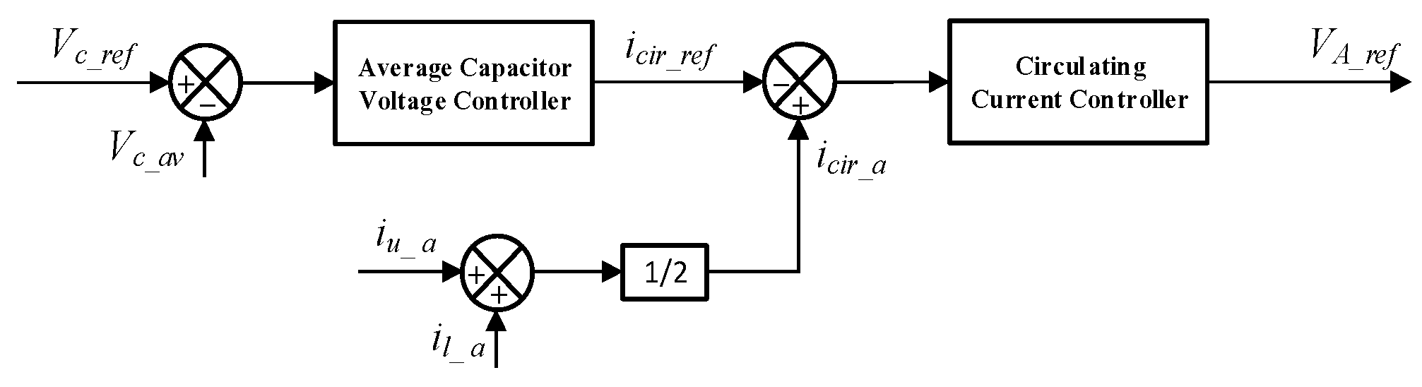
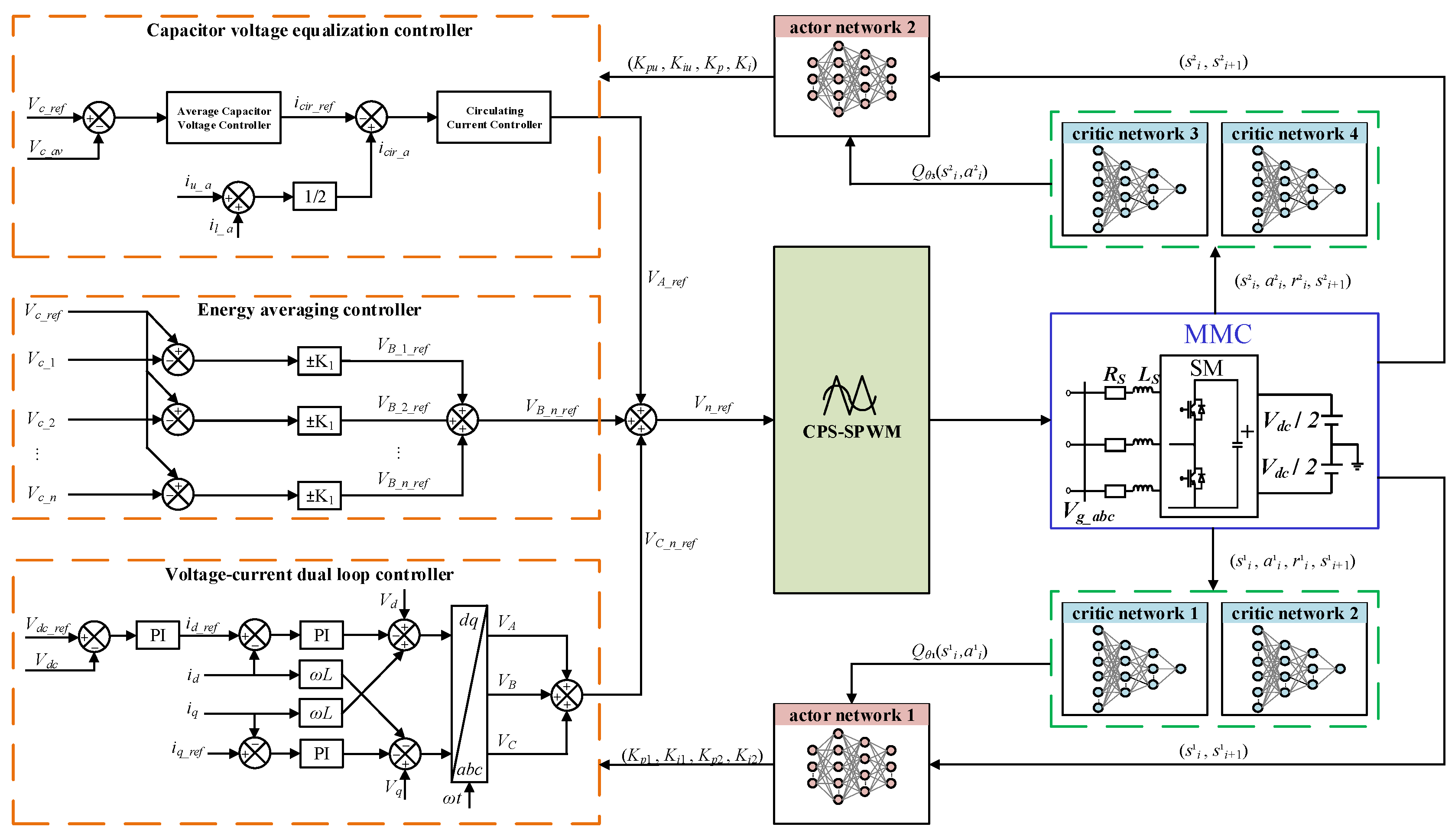
2.2. The Control Strategy of MMCs

Figure 3 illustrates the voltage and current dual-loop structure, which is widely employed in MMC control [35]. In this structure, id and iq represent the d-axis and q-axis components of the three-phase current, while Vd and Vq correspond to the d-axis and q-axis components of the three-phase voltage. Additionally, the DC output voltage is represented by Vdc, while the phase-locked loop generates the angular frequency ω.
Capacitor voltage balancing control consists of two components: energy averaging and voltage equalization. Given the three-phase symmetry, the subsequent analysis focuses on phase A as a representative example.
As shown in Figure 4, the energy averaging control regulates the average submodule capacitor voltage Vc_av through the outer voltage loop to track the reference value Vc_ref. The output of this loop serves as the reference input icir_ref for the inner circulating current controller, which suppresses circulating currents and ensures uniform energy distribution among the submodules [36]. When Vc_ref exceeds Vc_av, the circulating current reference icir_ref increases, promoting capacitor charging; conversely, a reduction in icir_ref induces capacitor discharging. By forcing the actual circulating current to track the reference value through feedback control, the independent circulating current loop ensures stable regulation of Vc_av under load disturbances. The formula for calculating Vc_av is provided below, with N corresponding to the number of submodules per arm.
V c _ a v = 1 2 N n = 1 2 N V c _ n
Voltage equalization control is determined by both the polarity of arm currents and the magnitude of capacitor voltage tracking errors in submodules. As shown in Figure 5, a proportional (P) controller modulates these reference voltages to enforce convergence toward their target values, with the proportional gain determining the trade-off between dynamic response and steady-state error. This closed-loop architecture guarantees submodule voltage uniformity under both transient and steady-state operating conditions.
Taking the upper arm of Phase A as an example, the capacitor voltage equalization control is adjusted based on the directions of the currents in both the upper and lower arms. Consequently, the polarity of VB_n_ref is determined by iu_a and il_a. When Vc_ref is greater than Vc_n, the converter must acquire energy from the DC side to charge the arm capacitor. Specifically, if iu_a is greater than 0, VB_n_ref becomes positive, and power flows into the converter; if iu_a is less than 0, VB_n_ref becomes negative, and power still flows into the converter. Conversely, when Vc_ref is less than Vc_n, the converter supplies energy to the DC side, causing the upper arm capacitor to discharge. In this case, if iu_a is greater than 0, VB_n_ref becomes negative, and power flows to the DC side; if iu_a is less than 0, VB_n_ref becomes positive, and power also flows to the DC side. The specific adjustment quantity for the capacitor voltage of the upper arm is given as follows:
V B _ n _ r e f = K 1 V c _ r e f V c _ n , i u _ a > 0 K 1 V c _ r e f V c _ n , i u _ a < 0 n = 1 , N
Similarly, the adjustment amount for the capacitor voltage in the lower arm is given as follows:
V B _ n _ r e f = K 1 V c _ r e f V c _ n , i l _ a > 0 K 1 V c _ r e f V c _ n , i l _ a < 0 n = 1 , N
Based on the single-phase equivalent circuit illustrated in Figure 2, the reference capacitor voltage value VC_n_ref for each submodule can be derived through the following relationship:
V C _ n _ r e f = V t _ a N + V d c 2 N   ( Upper   arm ) V C _ n _ r e f = V t _ a N + V d c 2 N ( Lower   arm )
Ultimately, the amplitude of the modulation wave for implementing the carrier phase-shifting strategy can be determined:
V n _ r e f = V A _ r e f + V B _ n _ r e f + V C _ n _ r e f
Consequently, the corresponding PWM signals can be generated to combine the output voltages of activated submodules, thereby synthesizing the arm output voltage waveform.
Most control strategies rely on PI controllers to achieve their functional objectives. Although they can achieve the objectives of stabilizing the DC-side output voltage of the MMC and balancing the capacitor voltages of the submodules, manual tuning of the PI controller parameters is required, and fixed parameters are insufficient to adapt to the complex operating conditions of the MMC. Notably, during dynamic processes, traditional PI control demonstrates limitations in response speed and overshoot suppression, which may lead to exacerbated voltage fluctuations in the submodules or failure in circulating current suppression. To address these limitations, this article proposes a DA-TD3 structure to dynamically adjust PI controller parameters. The methodology capitalizes on the end-to-end environmental perception and adaptive policy optimization capabilities of DRL, enabling effective management of the MMC’s complex and variable operating conditions. Section 3 provides a detailed explanation of the DA-TD3 structure’s principle and training parameters.

3. DA-TD3 Algorithm for Optimized Control of MMCs

The TD3 algorithm builds upon the DDPG algorithm, significantly improving stability and robustness. Furthermore, the dual-agent architecture attains equilibrium between dynamic response speed and steady-state accuracy through collaborative mechanisms [37]. The combination of these two approaches is thus better suited for addressing complex decision-making problems characterized by high coupling and multiple variables.

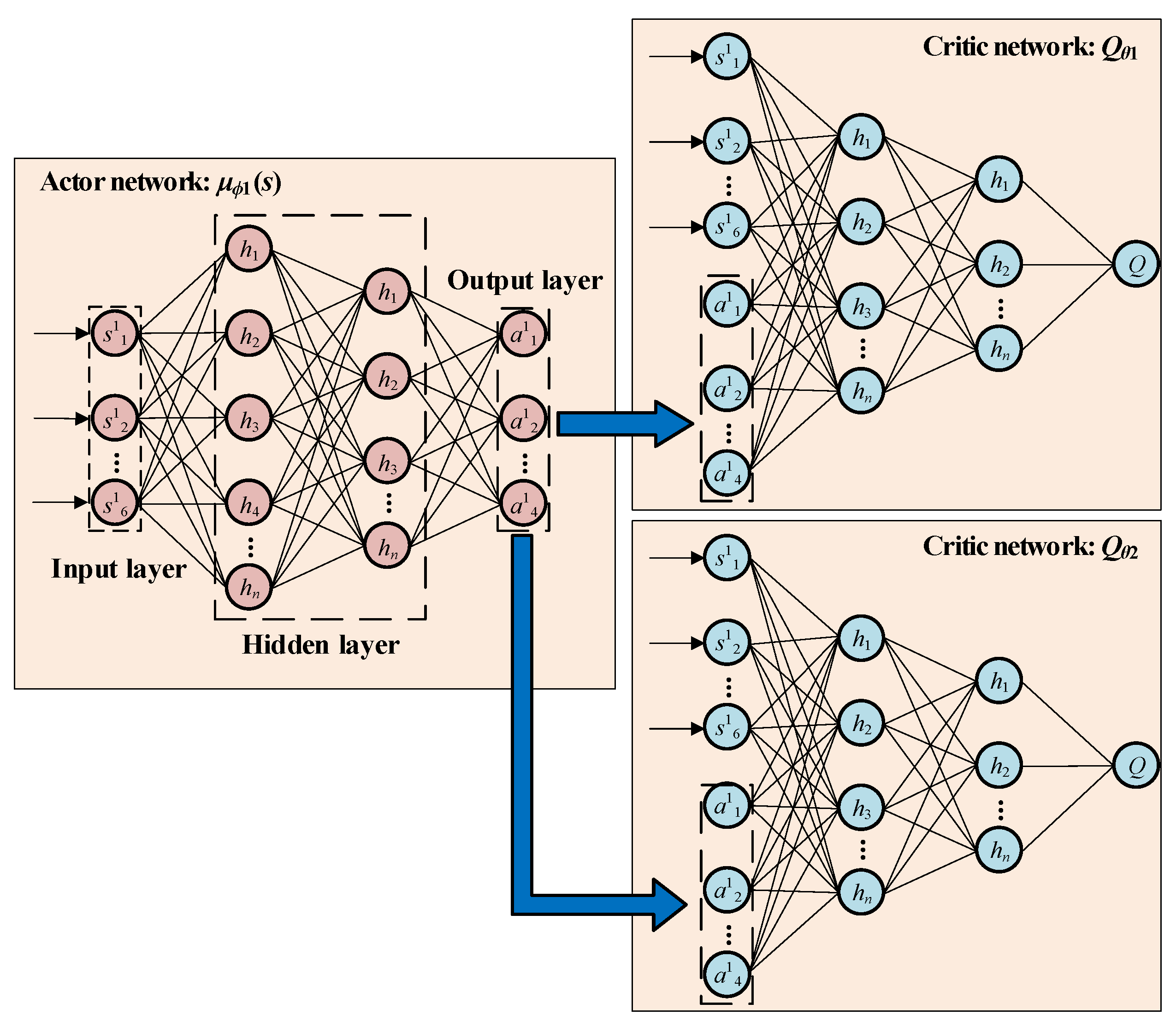
3.1. The Core Principles Underlying the TD3 Algorithm

In the TD3 algorithm, two independent critic networks (Q1 and Q2) are employed to estimate Q-values, which are parameterized by θ1 and θ2, respectively. In this article, a dual-agent framework is adopted, consisting of two actor networks (k = 1, 2) and four critic networks (j = 1, 2, 3, 4). Each agent (Agent 1 and Agent 2) utilizes two dedicated critic networks—Q1 and Q2 for the first agent and Q3 and Q4 for the second agent––with each critic network parameterized by its corresponding θj. All critic networks are updated synchronously through the recursive Bellman equation, expressed as follows:
Q π ( s k t , a k t ) = r ( s k t , a k t ) + γ k Q π s k t + 1 , π ( s k t + 1 ) , k = 1 , 2
To approximate the optimal Q function, the mean squared Bellman error function is utilized to quantify the degree to which θj satisfies the Bellman equation. The specific expression is as follows:
L ( θ j , R ) = E ( s , a , r , s ) ~ Q θ j ( s k , a k ) y k ( r k , s k ) 2 , k = 1 , 2 ;   j = 1 , 2 , 3 , 4
By employing clipped double Q-learning to compute Q-values and select the minimum target estimate, this dual mechanism effectively alleviates Q-value overestimation. Another key enhancement is target policy smoothing regularization, which involves adding a small random noise component ε to the target action, allowing the policy to explore the Q value function error, smooth the variations in actions, and prevent the critic network from overfitting at the narrow peaks of Q values [38]. Here, Gaussian noise is utilized, and the specific expression is as follows:
ε k ~ clip ( N k ( 0 , σ k ) , c k , c k ) , k = 1 , 2
Based on the above theory, the parameter update formula for the comment network is obtained as follows:
y k ( r k , s k ) = r k ( s k , a k ) + γ k m i n j = 1 , 2 , 3 , 4 Q θ j s k , π ϕ k ( s k ) + ε k ε k ~ c l i p ( N k ( 0 , σ k ) , c k , c k ) , k = 1 , 2
Here, rk(sk, ak) denotes the instantaneous reward, γk ∈ [0, 1] is the discount factor, σk specifies the standard deviation of Gaussian noise, and ck defines the truncation boundary.
The actor network can be updated via gradient ascent based on the expected return ∇ϕkJ(ϕk), which is formulated as follows:
ϕ k J ( ϕ k ) = E s k ~ R a k Q θ j ( s k , a k ) | a k = π ( s k ) ϕ k π ϕ k ( s k ) , k = 1 , 2   j = 1 , 3
The delayed policy update pertains to the circumstance where the actor network is updated only once for each d update of the critic network, with d being equal to 2 in this article, aiming to mitigate policy oscillation. Additionally, the TD3 algorithm likewise employs the soft update of the target network. The target network parameters are gradually synchronized using the soft update coefficient τk, enhancing stability. The soft weights (θj, ϕk) are updated according to the following expression:
S o f t   u p d a t e θ j τ k θ j + ( 1 τ k ) θ j , j = 1 , 2 , 3 , 4 ϕ k τ k ϕ k + ( 1 τ k ) ϕ k k = 1 , 2

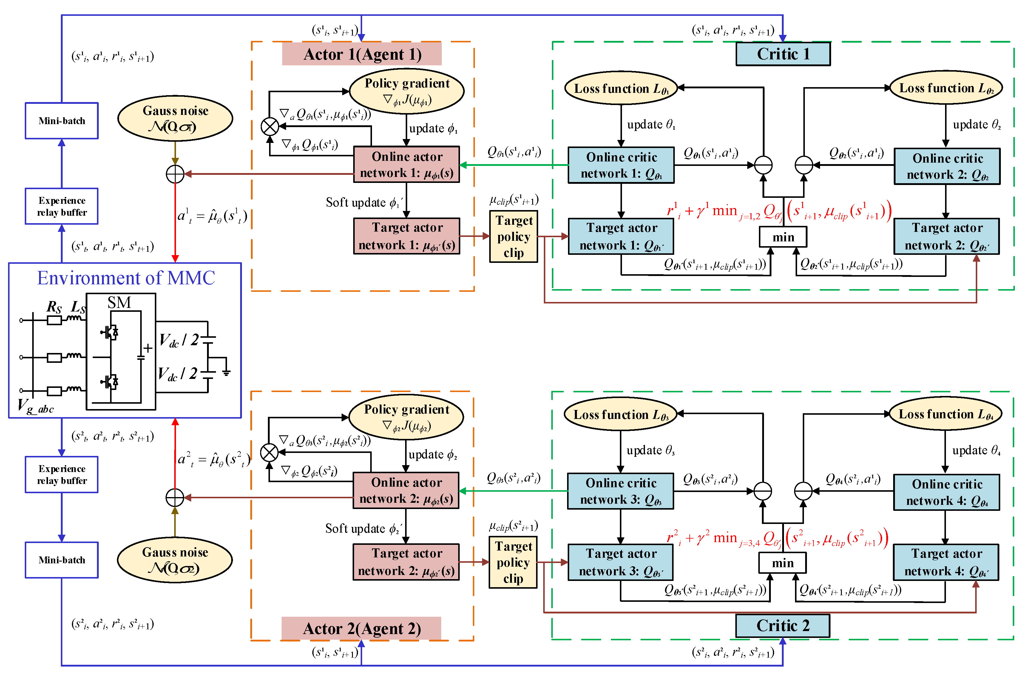
3.2. Dual-Agent Training Mechanism in DA-TD3

This article proposes a DA-TD3 collaborative control framework, as depicted in Figure 6, to address the multi-objective control requirements of MMCs. The architecture is developed based on the multi-agent Markov game framework [39] and incorporates three key collaborative mechanisms tailored to the multi-objective and strongly coupled nature of MMCs, as follows:
(1) Task decoupling mechanism: By isolating voltage and current dual-loop control (Agent 1) from capacitor voltage balance control (Agent 2), the traditional high-dimensional coupled control problem is transformed into two independent optimization tasks. Specifically, Agent 1 specializes in generating optimal double-loop PI parameters for dynamic control, while Agent 2 independently tunes capacitor voltage balancing control parameters to maintain steady-state equilibrium. Through orthogonal design of the action space, these agents achieve a specialized division of labor, effectively reducing control complexity.
(2) Target negotiation mechanism: A hidden communication channel between agents is established through the shared DC voltage error ΔVdc, its integral term, and asymmetric reward weights, enabling autonomous trade-offs between local optimization and global stability. This ensures that each agent can pursue its objectives while collaboratively maintaining the overall system performance.
(3) Collaborative parameter optimization mechanism: By differentially configuring hyperparameters, such as learning rates and exploration noises, and adjusting the network structures for the two agents, specialized control objectives are achieved. Specifically, Agent 1 employs high learning rates and exploration noise levels to rapidly track DC voltage dynamics and ensure transient stability, whereas Agent 2 operates with low learning rates and minimized exploration noise to maintain capacitor–voltage equilibrium while ensuring long-term steady-state accuracy.
Figure 7 illustrates the actor-critic network architecture of the agent. The subsequent sections will systematically elaborate on and analyze the construction of dual intelligent agents and their collaborative mechanisms.
For Agent 1 (voltage and current dual-loop control), the state space can be defined as S1 = [Δid, Δiq, ΔVdc, ∫Δid dt, ∫Δiq dt, ∫ΔVdc dt]. Specifically, Δid and Δiq represent the dq-axis current errors, while ΔVdc denotes the DC voltage tracking error. These errors capture the complete dynamic characteristics of both the dq-axis currents and the DC voltage regulation. The error components (Δid, Δiq, ΔVdc) directly quantify transient control deviations, serving as real-time system state indicators. The integral components (∫Δid dt, ∫Δiq dt, ∫ΔVdc dt) incorporate accumulated historical error information, thereby enhancing sensitivity to steady-state deviations.
The action space of Agent 1 can be defined as A1 = [Kp1, Ki1, Kp2, Ki2], where the voltage outer-loop PI parameters (Kp1, Ki1) and current inner-loop PI parameters (Kp2, Ki2) are dynamically adjusted through TD3’s policy in a continuous action space, enabling real-time parameter adaptation for enhanced control performance. During exploration, the agent improves through continuous trial-and-error learning, making the selection of an appropriate reward function R critical to guide its learning process. The reward function R1Vdc, Δid, Δiq, Vdc_ov) for Agent 1 is defined as follows:
R 1 = α 1 | Δ V d c | + α 2 | Δ i d | + α 3 | Δ i q | β V d c _ ov
Here, both α and β represent weighting coefficients, with Vdc_ov quantifying DC voltage overshoot. Given the critical role of DC voltage (Vdc) stability in determining the power transmission capacity of the MMC, the weighting coefficient α1 is assigned the highest weight to prioritize voltage regulation. Considering the dominant role of active current id in DC voltage regulation compared to iq, the secondary coefficient α2 is weighted heavier than α3. Furthermore, the reward function implements an overshoot penalty mechanism: when Vdc_ov exceeds the threshold Vov_th, the penalty term β· Vdc_ov is activated, effectively constraining the overshoot. Based on this design, and considering both control error minimization and training efficiency, after iteratively training the agent with various weightings, the final weighting ratio is determined as α123 = 10:3:2, β = 20, and Vov_th = 10%. Under these conditions, an agent with superior comprehensive performance can be achieved.
For Agent 2 (capacitor voltage balance control), the state space is defined as S2 = [ΔVdc, ΔVc, Δicir, ∫ΔVdc dt, ∫ ΔVc dt, ∫ Δicir dt]. Here, the DC voltage error ΔVdc serves as a shared state variable for the two agents, enabling coordinated control between them. ΔVc represents the capacitor voltage error, which reflects the energy imbalance of the submodules in the MMC. Δicir represents the circulating current error, which characterizes the energy exchange between the arms.
The action A2 = [Kpu, Kiu, Kp, Ki] output by Agent 2 corresponds respectively to the PI parameters of the voltage equalization control and the circulating current suppression control. The formulation of the reward function R2Vc, Δicir, ΔVdc, Vdc_ov) is described as follows:
R 2 = γ 1 | Δ V c | + γ 2 | Δ i c i r | + γ 3 | Δ V d c | β V d c _ ov
Among the terms, γ and β serve as weighting coefficients, while Vdc_ov denotes the DC voltage overshoot. Given that capacitor voltage balancing is essential for the reliable operation of the MMC and therefore serves as the primary control objective of Agent 2, the weighting coefficient γ1 associated with capacitor voltage balancing is assigned the highest priority among all control targets, followed by γ2 for circulating current suppression, which holds secondary priority in the control hierarchy. To mitigate inter-agent control conflicts with Agent 1, the weighting coefficient γ3 for DC voltage error is appropriately reduced. After extensive training and parameter tuning, the final weighting ratio is determined as γ1:γ2:γ3 = 20:10:1. Under these conditions, an agent with superior comprehensive performance can be achieved. Moreover, Agent 2 adopts the same overshoot penalty mechanism as Agent 1, where β = 20 and Vov_th = 10%. This design ensures that Agent 2 achieves capacitor voltage equilibrium while maintaining the stability of the main circuit.
Furthermore, the network architecture design in the TD3 algorithm constitutes a critical governing factor for agent training effectiveness. Structurally, the actor network of Agent 1 employs two hidden layers with 256 and 128 neurons, respectively. Critic network 1 utilizes a single hidden layer containing 128 neurons, while critic network 2 adopts three hidden layers with 64 neurons each. The actor network architecture of Agent 2 is identical to that of Agent 1. Additionally, both critic network 3 and critic network 4 incorporate two hidden layers with 256 and 128 neurons, respectively. The rectified linear unit (ReLU) is utilized as the activation function across all hidden layers, whereas the hyperbolic tangent (tanh) is employed for the output layer in the actor network. The training process of the DA-TD3 algorithm is detailed in Algorithm 1. In each episode, the states Si (i = 1, 2) are randomly sampled from the corresponding environment, and the action Ai is selected from the continuous action space.
Building upon the theoretical foundation established above, Figure 8 illustrates the overall control block diagram of the MMC system under DA-TD3 control. Through the collaborative mechanisms discussed in this section, DA-TD3 achieves real-time, precise tuning of PI parameters under complex MMC operating conditions. The framework demonstrates its core advantage by decoupling the high-dimensional coupled optimization problem in traditional centralized strategies into two coordinated low-dimensional subspace tasks. Moreover, through autonomous policy optimization, DA-TD3 overcomes the reliance on precise mathematical models and manual parameter adjustments while maintaining the engineering applicability of PI controllers.
Algorithm 1. DA-TD3 algorithm [32]
Input: Operating environment of the MMC
1: Initialize the actor network μϕ1 and critic networks Qθ1, Qθ2 for Agent 1. Initialize the actor network μϕ2 and critic networks Qθ3, Qθ4 for Agent 2.
2: Initialize target network parameters:
          φ 1 φ 1 ,   θ 1 θ 1 ,   θ 2 θ 2   φ 2 φ 2 ,   θ 3 θ 3 ,   θ 4 θ 4
3: Initialize independent replay buffers M1 and M2.
4: for episode = 1, 2, … N do
5:  Agents 1 and 2 select actions with exploration noise:
            a k ~ π ϕ k ( s k ) + ε k ,   ε k ~ N ( 0 , σ k )
6:  Perform joint action (a1, a2), observe rewards r1, r2, and new states s1′, s2′.
7:  Store interaction data in the reply buffers:
            M k ( s k , a k , r k , s k ) , k = 1 , 2
8:  Sample mini-batch of m1, m2 transition from reply buffers M1, M2.
9:  Compute greedy actions for the next states through
         a ˜ k π ϕ k ( s k ) + ε k ,   where   ε k ~ clip N ( 0 , σ ˜ k ) , c k , c k , k = 1 , 2
10:   Compete target Q-values according to (14)
11:   Update critic networks through:
         θ j argmin θ j m k 1 y k Q θ j ( s k , a k ) 2 , k = 1 , j = 1 , 2   and   k = 2 , j = 3 , 4
12:   if Episode mod 2 = 0 then
13:   Update actor networks ϕ1, ϕ2 by deterministic policy gradient according to (15)
14:   Update target networks according to (16)
15:   end if
16: end for

4. Algorithm Training and Simulation Analysis

4.1. Deep Reinforcement Learning Algorithm Training

To validate the effectiveness of the proposed methodology, an MMC model utilizing the DA-TD3 algorithm was constructed within the MATLAB/Simulink simulation platform. The hyperparameter settings for reinforcement learning training are detailed in Table 1, while the main parameters of the MMC system are listed in Table 2.

4.2. Simulation Analysis

This article establishes two operating conditions for analysis: (1) steady-state operation and (2) grid voltage sag. Under these operating conditions, the control performance of the intelligent agent trained with the DA-TD3 framework, the intelligent agent trained with DDPG algorithms, the PI controller based on a fuzzy algorithm, and the fixed-parameter PI controller for MMC systems was evaluated.

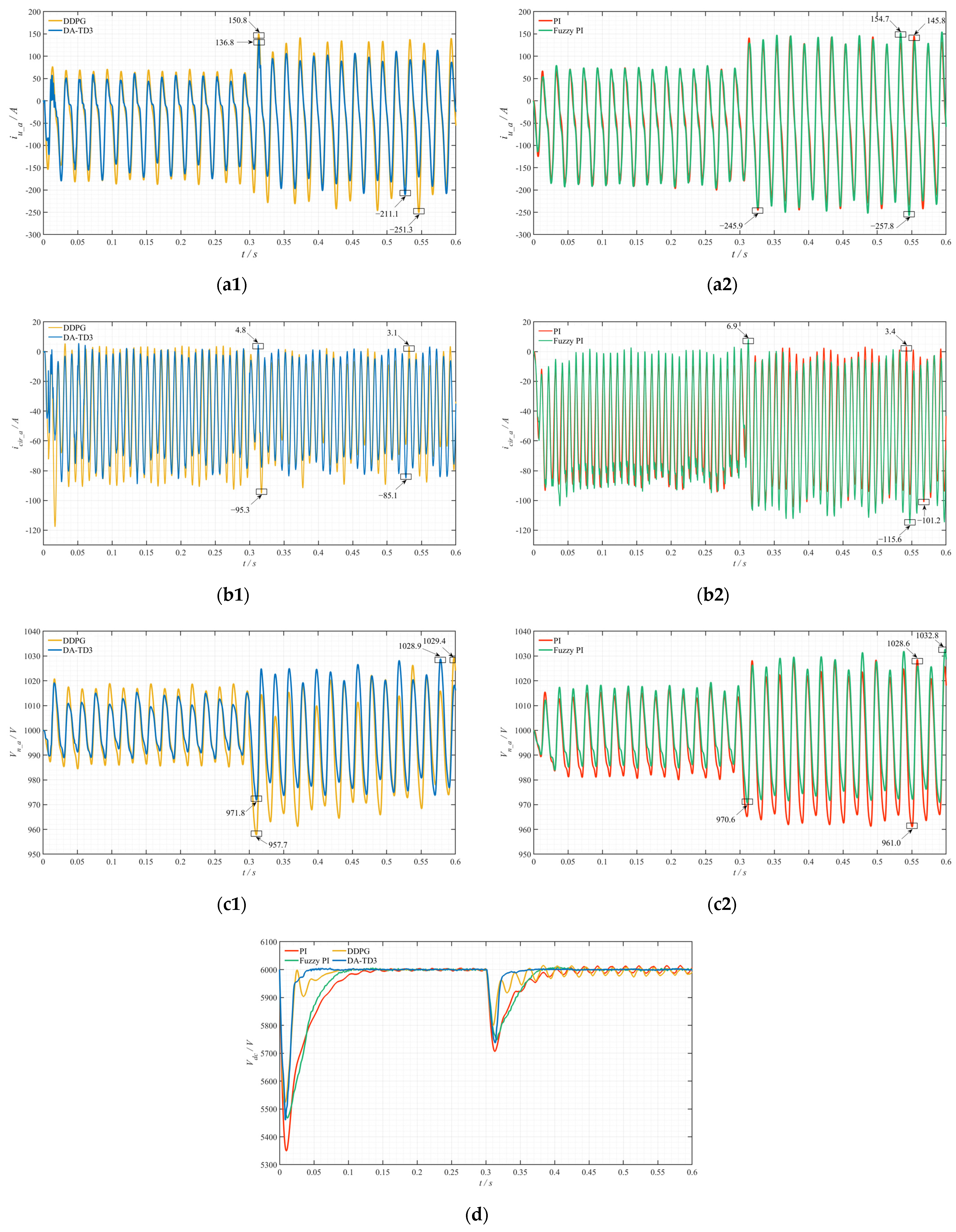
4.2.1. Steady-State Operating Condition

As illustrated in Figure 9, the steady-state performance of the DA-TD3 agent, DDPG agent, fuzzy PI controller, and conventional PI controller are comparatively analyzed through MMC simulations. The results indicate that DRL-based control strategies exhibit significantly enhanced dynamic response characteristics compared to traditional methods, though the DDPG agent demonstrates marginally inferior robustness relative to conventional approaches. The detailed findings are as follows:
The DA-TD3 agent achieves DC voltage regulation in 0.05 s, representing a 61.5% improvement over the conventional PI controller (0.13 s). It also outperforms both the DDPG agent (0.08 s) and fuzzy PI controller (0.1 s), confirming its superior rapid-response capability for complex operating conditions.
The DA-TD3 agent demonstrates smaller overshoot amplitudes compared to both fuzzy PI controllers and conventional PI controllers. While the DDPG agent achieves the minimal overshoot amplitude, its control system displays oscillations before reaching a steady state, suggesting compromised stability compared to the DA-TD3 agent.
In critical metrics such as submodule capacitor voltage, bridge arm current, and circulating current suppression, the MMC system controlled by the DA-TD3 agent demonstrates the best overall performance with minimal electrical quantity fluctuations and no abrupt changes. This further validates the DA-TD3 agent’s superiority in multi-task control scenarios.
In summary, the DA-TD3 agent achieves enhanced steady-state control performance compared to the DDPG agent, fuzzy PI controller, and conventional PI controller, delivering accelerated dynamic response and improved control precision.

4.2.2. Grid Voltage Sag Operating Condition

As illustrated in Figure 10, when the grid voltage drops to 0.7 pu at 0.3 s, the dynamic responses of critical electrical quantities in the MMC system are compared under control by the DA-TD3 agent, DDPG agent, fuzzy PI controller, and conventional PI controller. The results show that the DA-TD3-regulated DC voltage stabilizes within 0.05 s post-disturbance, maintaining consistency with its steady-state reference value, while the fuzzy PI controller requires 0.1 s for stabilization. In contrast, both the DDPG agent and conventional PI controller exhibit sustained DC voltage oscillations with slower response speeds. Regarding key indicators such as submodule capacitor voltage, arm current, and circulating current suppression, the DA-TD3 agent demonstrates the best overall performance.
In conclusion, the DA-TD3 agent exhibits superior dynamic response characteristics and anti-interference capabilities under grid voltage fluctuations, showcasing greater engineering application potential in complex MMC control scenarios.

5. Conclusions

This article addresses the following challenges in MMC dynamic control: complex and variable operating conditions, the inability of traditional controllers to fully meet control requirements due to reliance on empirical parameter tuning, and the difficulties in dynamic optimization of high-dimensional coupled multi-variable systems with complex mathematical models. A DA-TD3-based adaptive PI parameter control strategy is proposed. Through theoretical analysis and simulation verification, the following conclusions are drawn:
(1) Compared with traditional PI and fuzzy PI controllers, the DA-TD3 framework achieves dynamic optimization of PI parameters through its end-to-end autonomous learning mechanism, eliminating reliance on empirical parameter tuning. Its data-driven characteristics significantly enhance the controller’s adaptability to random disturbances and nonlinear operating conditions, addressing the dynamic performance limitations caused by fixed parameters in traditional methods.
(2) The DA-TD3 framework overcomes the shortcomings of DDPG algorithms, such as susceptibility to local optima and unstable convergence in complex systems, through the task decoupling mechanism, target negotiation mechanism, and collaborative parameter optimization mechanism between dual agents. Simulation results demonstrate that the DA-TD3 architecture exhibits superior robustness and dynamic response efficiency in multi-variable cooperative control, validating its potential in complex systems.
(3) The DA-TD3 framework avoids complex modeling and parameter derivation processes by leveraging DRL for autonomous policy optimization, eliminating dependence on precise mathematical models.
This framework provides an innovative solution for dynamic optimization control of MMC, demonstrating broad research prospects. Future research will focus on exploring technical solutions for algorithm lightweight design and migration learning-accelerated training while promoting iterative validation and scenario-specific deployment of the framework in hardware-in-the-loop simulation experiments and real-world engineering applications to expand its potential in engineering fields.

Author Contributions

Conceptualization, J.L. and W.G.; methodology, J.L.; software, J.L.; validation, W.G., Y.L. and Y.Z.; formal analysis, Y.Z. and Y.L.; investigation, J.L.; resources, W.G.; data curation, J.L. and Y.L.; writing—original draft preparation, J.L.; writing—review and editing, W.G.; visualization, Y.Z. and Y.L.; supervision, W.G. and Y.Z.; project administration, W.G.; funding acquisition, W.G. All authors have read and agreed to the published version of the manuscript.

Funding

This research was funded by Hunan Provincial Department of Education Scientific Research Project, grant number 22A0213.

Data Availability Statement

The data that supports the findings of this study are available from the corresponding author upon reasonable request.

Conflicts of Interest

The authors declare no conflict of interest.

References

  1. Khodayar, M.; Liu, G.; Wang, J.; Khodayar, M.E. Deep Learning in Power Systems Research: A Review. CSEE J. Power Energy Syst. 2021, 7, 209–220. [Google Scholar] [CrossRef]
  2. Dang, R.; Jin, G. High-Frequency Oscillation Suppression Strategy for Renewable Energy Integration via Modular Multilevel Converter—High-Voltage Direct Current Transmission System Under Weak Grid Conditions. Electronics 2025, 14, 1622. [Google Scholar] [CrossRef]
  3. Liu, Y.; Li, K.-J.; Liu, J.; Fan, H.; Sun, K. Start-up Control and Frequency Oscillation Control of the 100% Renewable Energy Islanded Grid Fed by MMC-HVDC System. In Proceedings of the 2023 5th Asia Energy and Electrical Engineering Symposium (AEEES), Chengdu, China, 23–26 March 2023; pp. 1644–1648. [Google Scholar]
  4. Chao, C.; Zheng, X.; Weng, Y.; Ye, H.; Liu, Z.; Liu, H.; Liu, Y.; Tai, N. High-Sensitivity Differential Protection for Offshore Wind Farms Collection Line with MMC-HVDC Transmission. IEEE Trans. Power Deliv. 2024, 39, 1428–1439. [Google Scholar] [CrossRef]
  5. Joshi, S.D.; Ghat, M.B.; Shukla, A.; Chandorkar, M.C. Improved Balancing and Sensing of Submodule Capacitor Voltages in Modular Multilevel Converter. IEEE Trans. Ind. Appl. 2021, 57, 537–548. [Google Scholar] [CrossRef]
  6. Li, J.; Sun, N.; Dong, H. Distributed Collaborative Optimization of Active Power Allocation for MMC-MTDC with Renewable Energy Integration. In Proceedings of the 2021 IEEE 4th International Electrical and Energy Conference (CIEEC), Wuhan, China, 28–30 May 2021; pp. 1–6. [Google Scholar]
  7. Huang, T.; Wang, B.; Xie, H.; Wu, T.; Li, C.; Li, S.; Hao, J.; Luo, J. Research on Reactive Power Control Strategy of MMC HVDC Converter. In Proceedings of the 2020 IEEE 4th Conference on Energy Internet and Energy System Integration (EI2), Wuhan, China, 30 October–1 November 2020; pp. 880–884. [Google Scholar]
  8. Niu, X.; Qiu, R.; Liu, S.; Chow, X. DC-Link Voltage Fluctuation Suppression Method for Modular Multilevel Converter Based on Common-Mode Voltage and Circulating Current Coupling Injection under Unbalanced Grid Voltage. Electronics 2024, 13, 3379. [Google Scholar] [CrossRef]
  9. Tavakoli, S.D.; Sánchez-Sánchez, E.; Prieto-Araujo, E.; Gomis-Bellmunt, O. DC Voltage Droop Control Design for MMC-Based Multiterminal HVDC Grids. IEEE Trans. Power Deliv. 2020, 35, 2414–2424. [Google Scholar] [CrossRef]
  10. Avdiaj, E.; D’Arco, S.; Piegari, L.; Suul, J.A. Frequency-Adaptive Energy Control for Grid-Forming MMCs Under Unbalanced Conditions. IEEE J. Emerg. Sel. Top. Ind. Electron. 2023, 4, 1124–1137. [Google Scholar] [CrossRef]
  11. Xi, Q.; Tian, Y.; Fan, Y. Capacitor Voltage Balancing Control of MMC Sub-Module Based on Neural Network Prediction. Electronics 2024, 13, 795. [Google Scholar] [CrossRef]
  12. Huang, C.; Tian, Y.; Chen, J. Circulating Current Suppression Combined with APF Current Control for the Suppression of MMC Voltage Fluctuations. Electronics 2025, 14, 64. [Google Scholar] [CrossRef]
  13. Wang, Z.; Yin, X.; Chen, Y. Model Predictive Arm Current Control for Modular Multilevel Converter. IEEE Access 2021, 9, 54700–54709. [Google Scholar] [CrossRef]
  14. Li, J.; Konstantinou, G.; Wickramasinghe, H.R.; Pou, J. Operation and Control Methods of Modular Multilevel Converters in Unbalanced AC Grids: A Review. IEEE J. Emerg. Sel. Top. Power Electron. 2019, 7, 1258–1271. [Google Scholar] [CrossRef]
  15. Wen, C.; Li, S.; Wang, P.; Li, J. An Input-Series Output-Parallel DC–DC Converter Based on Fuzzy PID Three-Loop Control Strategy. Electronics 2024, 13, 2342. [Google Scholar] [CrossRef]
  16. Chen, G.; Li, Z.; Zhang, Z.; Li, S. An Improved ACO Algorithm Optimized Fuzzy PID Controller for Load Frequency Control in Multi Area Interconnected Power Systems. IEEE Access 2020, 8, 6429–6447. [Google Scholar] [CrossRef]
  17. Yadav, S.K.; Patel, A.; Mathur, H.D. PSO-Based Online PI Tuning of UPQC-DG in Real-Time. IEEE Open J. Power Electron. 2024, 5, 1419–1431. [Google Scholar] [CrossRef]
  18. Kakkar, S.; Maity, T.; Ahuja, R.K.; Walde, P.; Saket, R.K.; Khan, B.; Padmanaban, S. Design and Control of Grid-Connected PWM Rectifiers by Optimizing Fractional Order PI Controller Using Water Cycle Algorithm. IEEE Access 2021, 9, 125941–125954. [Google Scholar] [CrossRef]
  19. Li, J.; Li, W. On-Line PID Parameters Optimization Control for Wind Power Generation System Based on Genetic Algorithm. IEEE Access 2020, 8, 137094–137100. [Google Scholar] [CrossRef]
  20. Antonio Acosta-Rodríguez, R.; Hernán Martinez-Sarmiento, F.; Ardul Múñoz-Hernandez, G. Design Methodology for Optimized Control of High-Power Quadratic Buck Converters Using Sliding Mode and Hybrid Controllers. IEEE Access 2025, 13, 49416–49432. [Google Scholar] [CrossRef]
  21. Liu, Y.; Lin, Z.; Xu, C.; Wang, L. Fault Ride-through Hybrid Controller for MMC-HVDC Transmission System via Switching Control Units Based on Bang-Bang Funnel Controller. J. Mod. Power Syst. Clean Energy 2023, 11, 599–610. [Google Scholar] [CrossRef]
  22. Isik, S.; Alharbi, M.; Bhattacharya, S. An Optimized Circulating Current Control Method Based on PR and PI Controller for MMC Applications. IEEE Trans. Ind. Appl. 2021, 57, 5074–5085. [Google Scholar] [CrossRef]
  23. Zhou, S.; Qin, L.; Ruan, J.; Wang, J.; Liu, H.; Tang, X.; Wang, X.; Liu, K. An AI-Based Power Reserve Control Strategy for Photovoltaic Power Generation Systems Participating in Frequency Regulation of Microgrids. Electronics 2023, 12, 2075. [Google Scholar] [CrossRef]
  24. Zhou, Y.; Zhou, L.; Yi, Z.; Shi, D.; Guo, M. Leveraging AI for Enhanced Power Systems Control: An Introductory Study of Model-Free DRL Approaches. IEEE Access 2024, 12, 98189–98206. [Google Scholar] [CrossRef]
  25. Duan, J.; Shi, D.; Diao, R.; Li, H.; Wang, Z.; Zhang, B.; Bian, D.; Yi, Z. Deep-Reinforcement-Learning-Based Autonomous Voltage Control for Power Grid Operations. IEEE Trans. Power Syst. 2020, 35, 814–817. [Google Scholar] [CrossRef]
  26. Khalid, J.; Ramli, M.A.M.; Khan, M.S.; Hidayat, T. Efficient Load Frequency Control of Renewable Integrated Power System: A Twin Delayed DDPG-Based Deep Reinforcement Learning Approach. IEEE Access 2022, 10, 51561–51574. [Google Scholar] [CrossRef]
  27. Yan, Z.; Xu, Y. A Multi-Agent Deep Reinforcement Learning Method for Cooperative Load Frequency Control of a Multi-Area Power System. IEEE Trans. Power Syst. 2020, 35, 4599–4608. [Google Scholar] [CrossRef]
  28. Zhang, H.; Sun, X.; Lee, M.H.; Moon, J. Deep Reinforcement Learning-Based Active Network Management and Emergency Load-Shedding Control for Power Systems. IEEE Trans. Smart Grid 2024, 15, 1423–1437. [Google Scholar] [CrossRef]
  29. Chen, Y.; Zhu, J.; Liu, Y.; Zhang, L.; Zhou, J. Distributed Hierarchical Deep Reinforcement Learning for Large-Scale Grid Emergency Control. IEEE Trans. Power Syst. 2024, 39, 4446–4458. [Google Scholar] [CrossRef]
  30. Cui, Q.; Hashmy, S.M.Y.; Weng, Y.; Dyer, M. Reinforcement Learning Based Recloser Control for Distribution Cables With Degraded Insulation Level. IEEE Trans. Power Deliv. 2021, 36, 1118–1127. [Google Scholar] [CrossRef]
  31. Wei, Z.; Quan, Z.; Wu, J.; Li, Y.; Pou, J.; Zhong, H. Deep Deterministic Policy Gradient-DRL Enabled Multiphysics-Constrained Fast Charging of Lithium-Ion Battery. IEEE Trans. Ind. Electron. 2022, 69, 2588–2598. [Google Scholar] [CrossRef]
  32. Tang, Y.; Hu, W.; Cao, D.; Hou, N.; Li, Z.; Li, Y.W.; Chen, Z.; Blaabjerg, F. Deep Reinforcement Learning Aided Variable-Frequency Triple-Phase-Shift Control for Dual-Active-Bridge Converter. IEEE Trans. Ind. Electron. 2023, 70, 10506–10515. [Google Scholar] [CrossRef]
  33. Liu, X.; Zhang, P.; Xie, H.; Lu, X.; Wu, X.; Liu, Z. Graph Attention Network Based Deep Reinforcement Learning for Voltage/Var Control of Topologically Variable Power System. J. Mod. Power Syst. Clean Energy 2025, 13, 215–227. [Google Scholar] [CrossRef]
  34. Wang, S.; Duan, J.; Shi, D.; Xu, C.; Li, H.; Diao, R.; Wang, Z. A Data-Driven Multi-Agent Autonomous Voltage Control Framework Using Deep Reinforcement Learning. IEEE Trans. Power Syst. 2020, 35, 4644–4654. [Google Scholar] [CrossRef]
  35. Hu, X.; Xiong, L.; You, L.; Han, G.; Xu, C. Comparative Analysis of Instantaneous Voltage Support Capability Under Voltage and Current Dual-Loop Control and Single-Loop Voltage Magnitude Control. In Proceedings of the 2024 IEEE 7th International Electrical and Energy Conference (CIEEC), Harbin, China, 10–12 May 2024; pp. 3797–3802. [Google Scholar]
  36. Jang, Y.-N.; Park, J.-W. New Circulating Current Suppression Control for MMC Without Arm Current Sensors. IEEE Trans. Power Electron. 2024, 39, 11232–11243. [Google Scholar] [CrossRef]
  37. Nguyen, T.T.; Nguyen, N.D.; Nahavandi, S. Deep Reinforcement Learning for Multiagent Systems: A Review of Challenges, Solutions, and Applications. IEEE Trans. Cybern. 2020, 50, 3826–3839. [Google Scholar] [CrossRef] [PubMed]
  38. Fan, Z.; Zhang, W.; Liu, W. Multi-Agent Deep Reinforcement Learning-Based Distributed Optimal Generation Control of DC Microgrids. IEEE Trans. Smart Grid 2023, 14, 3337–3351. [Google Scholar] [CrossRef]
  39. Zeng, Y.; Pou, J.; Sun, C.; Mukherjee, S.; Xu, X.; Gupta, A.K.; Dong, J. Autonomous Input Voltage Sharing Control and Triple Phase Shift Modulation Method for ISOP-DAB Converter in DC Microgrid: A Multiagent Deep Reinforcement Learning-Based Method. IEEE Trans. Power Electron. 2023, 38, 2985–3000. [Google Scholar] [CrossRef]
Figure 1. Topology of the MMC.
Electronics 14 02270 g001
Figure 2. Equivalent circuit model for single-phase MMC.
Electronics 14 02270 g002
Figure 3. Control structure of voltage and current dual loop.
Electronics 14 02270 g003
Figure 4. Control structure of the energy averaging.
Electronics 14 02270 g004
Figure 5. Control structure of the capacitor voltage equalization.
Electronics 14 02270 g005
Figure 6. Dual-agent adaptive PI control architecture for MMC.
Electronics 14 02270 g006
Figure 7. Actor-critic architecture in the DA-TD3 framework.
Electronics 14 02270 g007
Figure 8. DA-TD3-based overall control schematic for MMC.
Electronics 14 02270 g008
Figure 9. Waveforms of electrical quantities under steady-state operation: (a1,a2) arm current (illustrated with Phase A upper arm); (b1,b2) circulating current (demonstrated in Phase A); (c1,c2) submodule capacitor voltage (exemplified by a submodule in Phase A upper arm); and (d) DC output voltage.
Electronics 14 02270 g009
Figure 10. Waveforms of electrical quantities under grid voltage sag: (a1,a2) arm current (illustrated with Phase A upper arm); (b1,b2) circulating current (demonstrated in Phase A); (c1,c2) submodule capacitor voltage (exemplified by a submodule in Phase A upper arm); and (d) DC output voltage.
Electronics 14 02270 g010
Table 1. Main hyperparameters of the training process.
Parameter Value
Episode number (N)3000
Sample time (T1, T2)[1 × 10⁻³, 1 × 10⁻³]
Learning rate for the actor [λa1, λa2][1 × 10⁻⁴, 1 × 10⁻⁴]
Learning rate for the critic [λc1, λc2][2 × 10⁻³, 5 × 10⁻⁴]
Discount factor [γ1, γ2][0.995, 0.999]
Replay buffer size [M1, M2][1 × 10⁴, 1 × 10⁴]
Mini batch size [m1, m2][128, 128]
Target update frequency [FT1, FT2][2, 2]
Soft target update factor [τ1, τ2][1 × 10⁻³, 5 × 10⁻³]
Policy updates frequency [d1, d2][2, 2]
Exploration modelGaussian action noise
Initial value of noise standard deviation[0.3, 0.1]
Decay rate of the standard deviation[1 × 10⁻⁴, 1 × 10⁻⁵]
Agent 1PI parameter range [Kp1, Ki1, Kp2, Ki2]
0.05 ≤ Kp1 ≤ 12 ≤ Ki1 ≤ 2010 ≤ Kp2 ≤ 50100 ≤ Ki2 ≤ 500
Agent 2 PI parameter range [Kpu, Kiu, Kp, Ki]
0.5 ≤ Kpu ≤ 1210 ≤ Kiu ≤ 5001 ≤ Kp ≤ 2010 ≤ Ki ≤ 600
Table 2. System specifications of the MMC.
Parameter Value
Grid voltage Vg_abc (kV)3.3
DC output voltage Vdc (kV)6
Submodule capacitor C (mF)7
Arm resistance Rarm (Ω)0.04
Arm inductance Larm (mH)13.5
Grid equivalent resistance Rs (Ω) 0.04
Grid equivalent inductance Ls (mH) 10
Disclaimer/Publisher’s Note: The statements, opinions and data contained in all publications are solely those of the individual author(s) and contributor(s) and not of MDPI and/or the editor(s). MDPI and/or the editor(s) disclaim responsibility for any injury to people or property resulting from any ideas, methods, instructions or products referred to in the content.

