Article

Research on Repolarization Characteristic of PVDF Strain Sensor Used in Smart Tires

1
Jiaxing University, Jiaxing 314001, China
2
Institute of Acoustics, Chinese Academy of Sciences, Beijing 100190, China
3
Institute of Advanced Technology, University of Science and Techology of China, Hefei 230088, China
4
Anhui Mesateco Technology Co., Ltd., Hefei 230088, China
5
Shandong Linglong Tyre Co., Ltd., Yantai 265406, China
*
Author to whom correspondence should be addressed.
These authors contributed equally to this work.
Electronics 2025, 14(11), 2265; https://doi.org/10.3390/electronics14112265
Submission received: 21 April 2025 / Revised: 28 May 2025 / Accepted: 28 May 2025 / Published: 31 May 2025

Abstract

Piezoelectric polyvinylidene fluoride (PVDF) film sensors embedded in a tire can make the tire have a sense of tactile. Thus, PVDF strain sensors play an important role in smart tires. However, temperature tolerance of PVDF is a key issue limiting its application in smart tire as the embedding process needs high temperature vulcanization. This paper proposes a film repolarization method to treat PVDF film materials after high temperature vulcanization, which can be implemented to apply in smart tire. Variation in piezoelectric properties and its changing mechanism of PVDF film are analyzed with the methods of X-Ray Diffraction Spectroscopy (XRD) and Fourier Transform Infrared Spectroscopy (FTIR). Vulcanization process that PVDF film sensors undergo in tire applications are simulated. Furthermore, properties of the PVDF sensors with different process stages are simulated based on finite element model. An experimental platform of the PVDF sensors is set up and the drop rod experiments are conducted. Results verify the performance improvement of the repolarization strategy on embedded PVDF sensors. The effectiveness of the repolarization in the PVDF film shows a great significance for the application of strain sensors in smart tire.

1. Introduction

The measurement of deformation during tire movement is an important parameter in tire design and application, as it is significant for the vehicle’s power performance, stability, and safety [1,2,3,4,5]. Detection methods for deformation include acceleration measurement [6,7], optical detection [8,9], or strain gauge in situ detection [10,11,12,13,14,15]. Among these, the strain gauge in situ detection method is convenient for installation and embedding. It can also detect structural deformation states in real-time, which does not rely on too much detection equipment and data analysis systems. More importantly, in situ embedded detection can not only detect surface deformation but also internal deformation of the structure, which is crucial for smart tire applications.
Polyvinylidene fluoride (PVDF) films and their copolymers, such as PVDF-TrFE, are piezoelectric strain gauges with advantages of withstanding large deformation [16,17]. Thus, they have a broad application prospect in the field of tire deformation monitoring [18]. Other types of piezoelectric thin films, such as piezoelectric ceramics and piezoelectric single crystal materials, have high piezoelectric performance and material stability, but their material brittleness limits their measurement use in tires. However, the biggest issue limiting the application of this type of film sensor in smart tire (as shown in Figure 1) is their temperature tolerance [19,20]. The tire production process inevitably involves vulcanization, where the vulcanization temperature of rubber materials generally needs to be between 130 °C and 180 °C [21,22]. This temperature exceeds the Curie point of PVDF-based film materials by a big margin. For most piezoelectric materials, depolarization occurs when the environmental temperature is higher than the Curie point [23]. At this temperature, the ordered β phase in the PVDF-based material becomes disordered. Moreover, the piezoelectric β phase may transform into a non-piezoelectric α phase, leading to performance decrease in the piezoelectric properties of the material. This will result in a lower signal-to-noise ratio of the sensor, making it difficult to extract effective structural deformation signals. Material modification is one strategy for overcoming the issue of a low Curie point, but modifying fluorine materials is a great challenge. Finding out how to improve the application temperature tolerance of PVDF film materials based on existing materials is the key factor to enabling the large-scale application of PVDF piezoelectric film sensors.
During the entire process of tire preparation and application [21], the PVDF film sensor only undergoes a high-temperature vulcanization process for 30–40 min, and then the temperature remains below the Curie point for the rest of the time. This situation provides users with the opportunity to improve the signal-to-noise ratio, compared with application in a complete high-temperature environment.
This paper proposed a method of repolarization for PVDF film materials after high temperature vulcanization in smart tire applications. The repolarization method can be understood as a secondary polarization of the depolarization film to restore its original piezoelectric properties as much as possible. First, the mechanism of depolarization of PVDF piezoelectric films caused by high temperature was studied. Properties were analyzed through macroscopic and microscopic testing methods. Then, a method for film repolarization was proposed to restore the piezoelectric performance of the film material. The analysis revealed that the β phase structure content of the films was also restored at the microscopic level. Finally, a PVDF film piezoelectric sensor was fabricated and embedded into rubber for simulating high temperature vulcanization. An experimental platform of the PVDF sensors was set up and the drop rod experiments were conducted. Experimental results showed that the piezoelectric signal of the repolarized sensors was significantly improved.

2. Temperature Characteristics and Depolarization Mechanism of PVDF Films

Piezoelectric PVDF film materials undergo two stages in embedded tire applications, including before vulcanization and after vulcanization. After vulcanization, the film material was depolarized, which leads to a performance decrease in the signal-to-noise ratio and detection sensitivity. For the film material, the mechanism of the piezoelectric properties changing with temperature and the duration time are studied.

2.1. Sample Preparation and Characterization

Among piezoelectric film materials, the uniaxial stretching PVDF film has a relatively stable manufacturing process and broad application. Thus, the experimental samples used in this paper were uniaxial stretching PVDF piezoelectric film material with a nominal temperature up to 125 °C. The thickness of the film sample was 110 μm, with a rectangular dimension of 10 mm by 40 mm.
The piezoelectric equation of PVDF film can be represented by the following matrix.
q 1 q 2 q 3 = 0 0 0 0 d 11 0 0 0 0 d 24 0 0 d 31 d 32 d 33 0 0 0 σ 11 σ 22 σ 33 σ 23 σ 31 σ 12
In the formula, qi (i = 1,2,3) represents the charge density in three directions, with the unit of pC/mm2. dij (i = 1, 2, 3; j = 1, 2, 3) represents the piezoelectric constant, with the unit of pC/N, where the subscript i indicates the normal direction of the polarization charge and j indicates the direction of the applied force. σij represents the PVDF stress tensor, with the unit of MPa. The output of the charge amount outside the plane is:
q 3 = d 31 σ 11 + d 32 σ 22 + d 33   σ 33
Without considering lateral deformation, the above equation can be further simplified to Q = d33 × σ33 [24]. The main deformation that occurs during tire movement is compression. Thus, the material’s piezoelectric properties are determined by d33, which can be measured using a d33 tester.
In this paper, temperature effect and crystal phase analysis of PVDF film materials were investigated using experimental methods including Differential Scanning Calorimetry (DSC), Fourier Transform Infrared Spectroscopy (FTIR), and X-Ray Diffraction Spectroscopy (XRD).
DSC experiments can obtain the Curie point and melting point of piezoelectric materials. The Curie point indicates the performance degradation of piezoelectric thin films, while the melting temperature signifies that the thin film material undergoes deformation, such as shrinkage and curling. The Curie point and melting point are used to confirm the macroscopic performance degradation temperature of PVDF films and the maximum tolerance temperature of the thin film.
FTIR and XRD experiments can obtain the crystal phase structure and its content in PVDF films by analyzing diffraction peak intensities at various angles. This can explain the fundamental reasons for the change in d33 from a microscopic perspective.
PVDF piezoelectric film material can maintain very stable piezoelectric properties below 80 °C. Therefore, the study starts from 90 °C up to the melting temperature with an interval of 10 °C. This temperature range covers the vulcanization temperature of tire rubber materials (150 °C). The effect of temperature on the material is studied using an oven. Measurements are conducted after being held at that temperature for 30 min. The polarization process of PVDF film material is a slow phase transition process, and the transition from the non-piezoelectric α phase to the piezoelectric β phase [25,26] requires overcoming significant structural resistance.

2.2. Analysis of PVDF Depolarization Mechanism

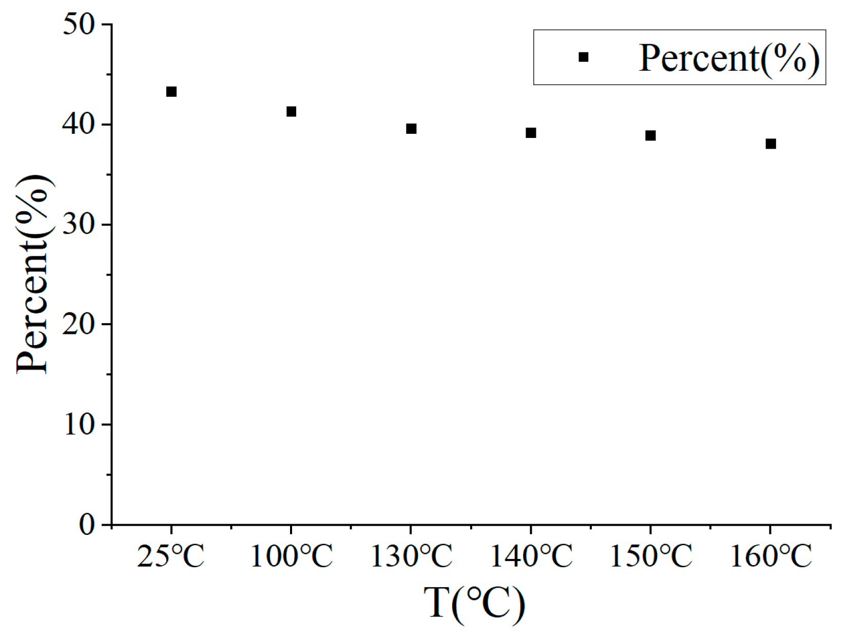
2.2.1. Temperature-Dependent Effect

This paper conducted DSC experiments to analyze temperature properties of PVDF film materials. In agreement with the conclusions of the literature [19], no Curie point was found for the homopolymer PVDF material within the measured temperature range in this paper. This result further confirms that the properties of homopolymer PVDF and copolymer PVDF-Trfe are different in terms of thermal response. Fortunately, the absence of a Curie point within the temperature range shown in Figure 2 means that the properties of the material will not undergo significant abrupt changes within this range. Thus, homopolymer PVDF piezoelectric film is commonly used as a sensor functional element. The only peak shown in Figure 2 is the melting temperature of PVDF. This melting temperature is 166 °C, higher than the vulcanization temperature of rubber materials at 150 °C.
The piezoelectric properties of PVDF film material do not change below 80 °C. Figure 2b shows the property of d33 for PVDF film material in the temperature range of 90 °C to 170 °C. From the figure, it can be seen that the d33 (15.0 pC/N) does not change significantly in the temperature range of 90–130 °C. When the temperature exceeds 140 °C, d33 of PVDF gradually decreases. At 150 °C, which is equal to the rubber vulcanization temperature, d33 value is about 10.5 pC/N. At 170 °C, the material begins to melt and its d33 degrades to only 6–7 pC/N.

2.2.2. Time-Dependent Effect

The process of transforming from the β phase to the α phase takes about 20–30 min. As the d33 of PVDF films does not change significantly below 130 °C, the piezoelectric property time-dependent study is conducted in the range of 140 °C to 170 °C. During the vulcanization process, the sensor is kept at the vulcanization temperature for nearly 1800 s. To understand the decreasing trend of piezoelectric properties of PVDF films over time, the time-dependent effect of 60 s, 120 s, 300 s, 480 s, 600 s, 1200 s, and 1800 s was tested in this study. In the experiment, the sample was placed in an oven that has reached the set temperature. After keeping the sample in the oven for half an hour, it was taken out and left to cool naturally to room temperature.
Experimental results show that d33 decreases under all tested temperature conditions as shown in Figure 3. At the initial moment, d33 decreases rapidly. As time duration increases, the rate of decrease in d33 slows down and eventually tends to be stable. From the figure, it can also be seen that the higher the temperature, the faster the initial piezoelectric performance of PVDF films decays and the value of d33 lowers eventually.

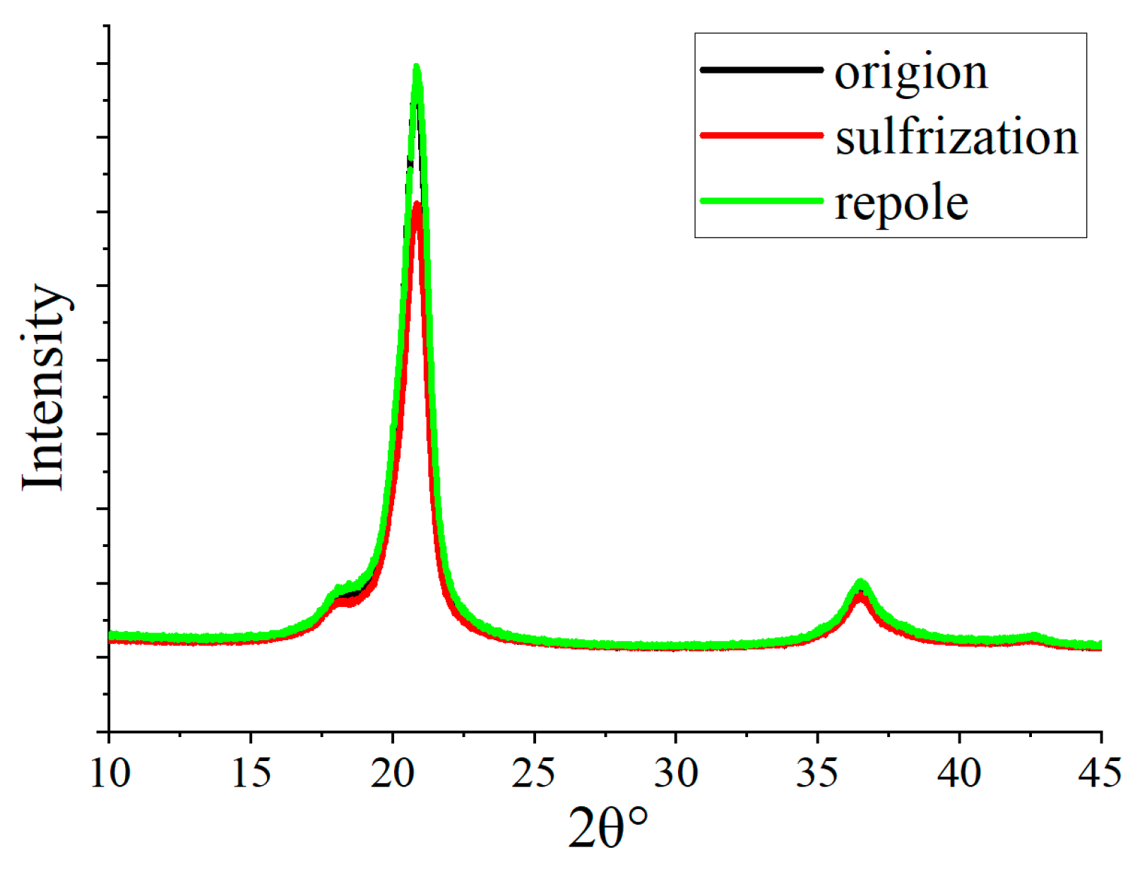
2.2.3. Structure Change in the PVDF Depolarization

To further analyze the mechanism of the change in piezoelectric properties of the PVDF material after high temperature treatment, XRD and FTIR were used to study the crystal phase structure of the PVDF material.
As shown in Figure 4, XRD results indicate that the maximum peak intensity occurs at 2θ angles of 20.7°, which represent the 110 and 200 planes of the β phase [27,28]. This means that the β phase occupies a very large proportion in the piezoelectric PVDF film material. In addition, there is a small peak near 18°, which is the diffraction peak of the α and γ crystal phases. The contribution of these two phases to the piezoelectric properties is very weak.
With increase in temperature, the crystal plane diffraction peak decreases, which means the content of the β phase decreases. Within the temperature range studied in this article, the β phase still occupies a relatively large proportion and does not drop to half of the room temperature even at the highest temperature of 160 °C.
Figure 5 presents the FTIR results of the piezoelectric PVDF film, with diffraction peaks of the β phase at 510 cm−1, 840 cm−1, and 1175 cm−1. Peaks at 614 cm−1 and 764 cm−1 correspond to the α phase diffraction [29,30]. It can be seen that the crystal structure is predominantly composed of α and β phases.
The content of the β phase can be calculated using the following formula:
Fβ = Aβ/(Aβ + 1.26Aα)
where Fβ represents the content of the β phase, and Aα and Aβ represent the absorption peak widths of the α and β phases in the FTIR graph, respectively. The calculated results are shown in Figure 6. It can be seen that the content of the β phase changes from 43% at 25 °C to 38% at 160 °C. Compared to the decrease in d33 from 15 pC/N to 7 pC/N in Figure 3, the amount of phase structure transformation from β phase to α phase is very small. From this point, it can be seen that the d33 change in the PVDF material studied in this article is not caused by phase transition. Thus, it is inferred that in a short-term high-temperature environment, the β phase does not directly transform into the α phase. Instead, as the temperature rises, the binding between the material structures weakens and the orientation of the β phase shifts, changing from an ordered arrangement to a disordered one, leading to a decrease in d33.

2.3. Repolarization Method and Implementation

To improve the performance of PVDF sensor after vulcanization, repolarization method is proposed. For PVDF materials, corona polarization is often used to give the film piezoelectric properties. However, in the application of tire scenarios, PVDF film is wrapped and cannot be subjected to corona polarization, so contact polarization is used for repolarization. The repolarization requires using metal copper foil pasted on both sides of the PVDF film as the positive and negative poles of polarization. High voltage is input through the pins of the flexible circuit board to repolarize the film. The repolarization voltage starts from 100 MV/m to 300 MV/m [31], with an interval of 50 MV/m. The repolarization time duration is uniformly set at 30 min. After repolarization, d33 of the material is analyzed.
Results of d33 in the polarized PVDF film are shown in Figure 7. It can be seen that as the voltage increases, the piezoelectric performance of the film improves. At a voltage of 250 MV/m, the piezoelectric performance of the PVDF film recovers to its pre-high state, with a d33 of 15.0 pC/N. By further increasing the voltage, d33 can continue to increase reaching nearly 16 pC/N, exceeding the original d33 of the film. However, at a repolarization voltage of 300 MV/m, some areas of the film have already exhibited electrical breakdown, and a burnt hole appeared on the film, which can be seen from Figure 7. After the breakdown, the positive and negative are short-circuited, making it unable to be used as a sensor.
To analyze the mechanism of the PVDF in the process of repolarization, XRD were conducted. As shown in Figure 8, it can be seen that the content of the β phase decreases first and then increases. The peak intensity after repolarization has returned to the initial state. Thus, the film can be restored to its original performance. In addition, if the repolarization of PVDF film is carried out under certain temperature conditions (70–130 °C), it can further reduce the voltage and time duration, which can improve the polarization efficiency. We also conducted FTIR experiments on the repolarized PVDF, and the experimental results showed that the content of β phase was around 40%. The experimental results further indicate that short-term high temperature and polarization have a greater impact on the orientation of the β phase.

3. Performance Verification of PVDF Sensor

3.1. Simulation Analysis of PVDF Sensor

Before implementing the application of strain sensors, the electrical response characteristics of PVDF were simulated by using the finite element method.
Firstly, as shown in Figure 9, a simulation model of an equivalent “sandwich structure” was constructed based on the actual form of the PVDF sensor. The model includes the upper electrode layer Cu, the PVDF piezoelectric layer and the lower electrode layer Cu. The structural parameters of each part were set as the length of 40 mm, the width of 10 mm, and thickness of 110 um.
Material property parameters were set for the structural components as shown in Table 1. Among them, the PVDF piezoelectric film was assigned different values based on the actual d33 measured before and after vulcanization.
To simulate, the electrode material was set as a solid mechanics field, and the piezoelectric PVDF film was set as a coupled piezoelectric field of solid mechanics and electrostatic field.
Then, boundary conditions were set. The upper electrode was set as a grounded terminal and the lower electrode was set as a terminal. Free boundary conditions were used on both sides of the film. A point load excitation was applied vertically downward on the upper surface of the film, with the force magnitude of 1 N.
By calculating the simulation model, the deformation changes and charge distribution of PVDF can be obtained. A cross-section was taken along the central axis in the Y direction on the surface of PVDF. The charge distribution of PVDF on cross-section was extracted.
Calculation results are shown in Figure 10. As seen in the figure, the maximum electrical potential of the film reaches 1.61084 V after repolarization (25 °C), which is approximately 1.3 times than that of the un-repolarization film 1.17293 V (150 °C). Simulation results demonstrate the beneficial effects of repolarization.

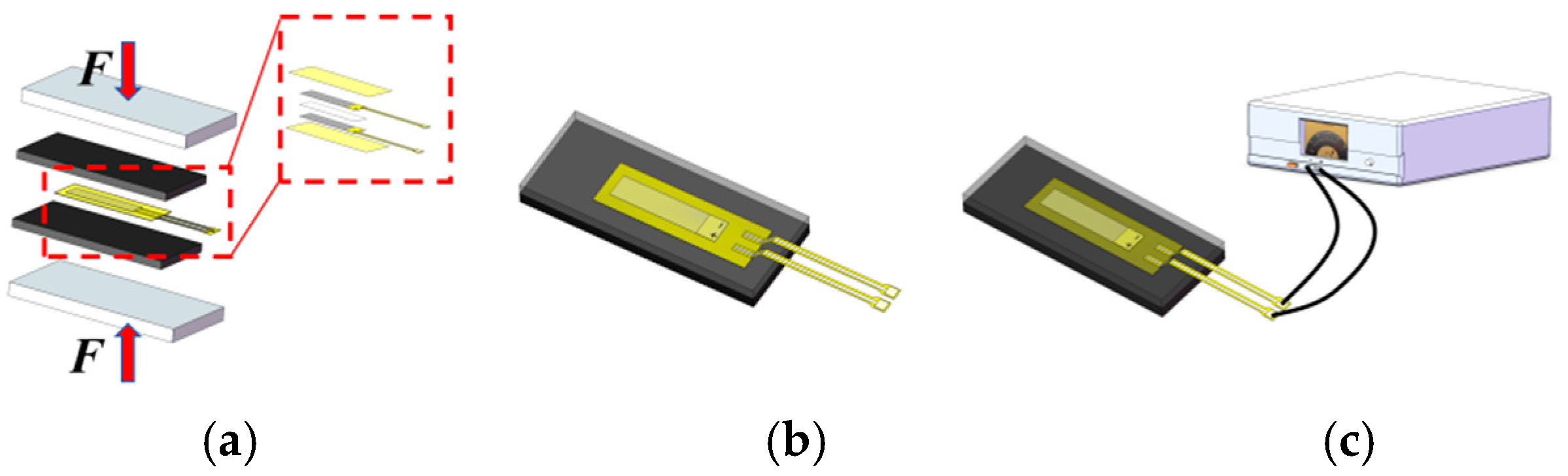
3.2. Experimental Set Up of PVDF Sensor

In this section, an experimental set up was used to simulate the vulcanization process. The sensor embedding process can be seen in Figure 11. The embedded sensor employs a sandwich structure, including a piezoelectric film layer, two electrode layers and two insulating encapsulation layers. A heating press plate was used to apply high temperature and pressure to the rubber material. Each rubber sheet has a thickness of 5 mm. The pressure of the press was set to 2 MPa and the pressing time was set to 30 min at 150 °C, simulating the normal vulcanization time for tires. The post-vulcanization sensor is shown in Figure 11b. Repolarization method proposed in this paper was conducted through the reserved electrical terminals as shown in Figure 11c.
Experiments on rubber sensor devices were conducted using a drop weight experimental platform, as shown in Figure 12. A steel rod with a diameter of 10 mm can control the force by adjusting its height within the range of 0–150 mm. A pressure sensor was placed between the marble base and the drop weight to measure the force generated during the drop weight impact.
Performance experiments were performed on both vulcanized and repolarized devices. By collecting the piezoelectric signals under different impact heights, a force–electricity correlation for the device was established. This force–electric correlation allows for a more intuitive comparison of the sensitivity between vulcanized devices and repolarized devices.

3.3. Verification of Sensor Performance

To ensure the reliability of the device, experiments were conducted. A DC voltage of 250 MV/m for repolarization on the device after vulcanization was applied. The repolarization time was set as 30 min. The drop rod height was selected from 30 mm to 150 mm, with an interval of 30 mm.
Figure 13a,b show the piezoelectric responses of the sensor at different drop rod impact heights, respectively. From the comparison in the figure, it can be seen that the piezoelectric response of the sensor after vulcanization is almost half of the repolarized sensor. The values shown on the right side of Figure 13a represent the impact force at different drop rod heights. For example, the impact force at a height of 90 mm was 1099 N. At this point, the output voltages of the two types of sensors were 7.2 V and 3.4 V, respectively. From Figure 13a,b, we can see that under the same loading pressure, the output voltage of the device after repolarization is approximately twice that of the device after vulcanization, which is consistent with the relationship between the d33 of the PVDF film after repolarization and the d33 of the PVDF film after vulcanization. Figure 13c summarizes the piezoelectric responses of the sensors with two types under drop rod. By performing linear fitting on the data, the formula V = KF can be used to characterize the piezoelectric response of PVDF film sensors. In the formula, V represents the output voltage of the sensor, F represents the pressure applied to the sensor, and K represents the sensitivity coefficient.
The sensitivity coefficient K1 = 7.5 × 10⁻³ V/N of the repolarized sensor and K2 = 3.7 × 10⁻³ V/N of the sensor after vulcanization were calculated from the experimental data. It showed that repolarization was an effective method to improve the sensitivity of piezoelectric film sensors after high-temperature treatment.

4. Conclusions

Temperature tolerance of PVDF is a key issue limiting its application in smart tires as the embedding process needs high temperature vulcanization. This paper proposes a film repolarization method to treat PVDF film materials after high temperature vulcanization.
Variation in piezoelectric properties and the changing mechanism of PVDF film were analyzed and tested by the methods of XRD and FTIR. Studies have shown that the piezoelectric properties of the PVDF film used do not change below 130 °C, but there is a significant attenuation between 130 and 160 °C. The vulcanization process that PVDF film sensors undergo in tire applications were also simulated. Furthermore, properties of the PVDF sensors with different process stages were analyzed based on the finite element model and drop rod experiments were conducted. Results show the performance improvement of the repolarization strategy on embedded PVDF sensors.
The effectiveness of the repolarization in the PVDF film shows great significance for the application of strain sensors in smart tires and broadens the application scenarios of piezoelectric sensors.

Author Contributions

Conceptualization, Y.H., Y.T. and R.T.; methodology, Y.H.; software, Y.T.; validation, R.T., B.L. and M.S.; formal analysis, Y.T. and B.L.; investigation, Y.H. and R.T.; data curation, Y.H. and R.T. writing—original draft preparation, Y.H.; writing—review and editing, Y.T. and R.T.; visualization, B.L. and M.S.; supervision, B.L. and M.S.; project administration, Y.T., B.L. and M.S.; funding acquisition, Y.T. and B.L. All authors have read and agreed to the published version of the manuscript.

Funding

This work was supported in part by the National Key Research and Development Program of China under Grant No. 2022YFB3206601, in part by the National Natural Science Foundation of China under No. 12202398, in part by Youth Innovation Promotion Association, Chinese Academy of Sciences under Grant No. 2022024, and in part by China Institute of loT and WUXI IOT Innovation Promotion Center.

Data Availability Statement

Data can be obtained from the authors.

Conflicts of Interest

Author Ruitao Tang was employed by the company Anhui Mesateco Technology Co., Ltd. Author Bo Lu and Mingliang Song was employed by the company Shandong Linglong Tyre Co., Ltd. The remaining authors declare that the research was conducted in the absence of any commercial or financial relationships that could be construed as a potential conflict of interest.

References

  1. Xing, C.; Zhang, Q.; Wang, Z.; Guo, J.; Li, M.; Yu, D.; Wang, Y.; Zhou, Q.; Tang, W.; Li, Z.; et al. Soft-metal bonding-enabled recyclable and anti-interference flexible multilayer piezoelectric sensor for tractor tire strain monitoring. Nano Energy 2024, 127, 13. [Google Scholar] [CrossRef]
  2. Fu, H.; Zhang, J.; Luo, X.; Yin, Y.; Yang, B.; Ni, S.; Jiang, Z. An intelligent tire force estimation correction method based on wheel spoke strain. Sens. Actuators A Phys. 2024, 380, 116023. [Google Scholar] [CrossRef]
  3. Zhang, J.; Fu, H.; Yang, B.; Ni, S.; Huo, R.; Lian, C. A spoke strain-based method to estimate tire condition parameters for intelligent tires. Sens. Actuators A Phys. 2024, 367, 11. [Google Scholar] [CrossRef]
  4. Zhao, W.; Zhang, C.; Zhang, J. Continuous measurement of tire deformation using long-gauge strain sensors. Mech. Syst. Signal Process. 2020, 142, 106782. [Google Scholar] [CrossRef]
  5. Liu, Z.; Gao, Q. Development of a flexible belt on an elastic multi-stiffness foundation tire model for a heavy load radial tire with a large section ratio. Mech. Syst. Signal Process. 2019, 123, 43–67. [Google Scholar] [CrossRef]
  6. Vázquez, V.F.; Hidalgo, M.E.; García-Hoz, A.M.; Camara, A.; Terán, F.; Ruiz-Teran, A.M.; Paje, S.E. Tire/road noise, texture, and vertical accelerations: Surface assessment of an urban road. Appl. Acoust. 2020, 160, 107153. [Google Scholar] [CrossRef]
  7. Tang, Y.; Tao, L.; Li, Y.; Zhang, D.; Zhang, X. Estimation of tire side-slip angles based on the frequency domain lateral acceleration characteristics inside tires. Machines 2024, 12, 229. [Google Scholar] [CrossRef]
  8. Zhang, J.; Kong, X.; Obrien, E.J.; Peng, J.; Deng, L. Noncontact measurement of tire deformation based on computer vision and Tire-Net semantic segmentation. Measurement 2023, 217, 14. [Google Scholar] [CrossRef]
  9. Xiong, Y.; Tuononen, A. A laser-based sensor system for tire tread deformation measurement. Meas. Sci. Technol. 2014, 25, 115103. [Google Scholar] [CrossRef]
  10. Matsuzaki, R.; Hiraoka, N.; Todoroki, A.; Mizutani, Y. Analysis of applied load estimation using stain for intelligent tires. J. Solid Mech. Mater. Eng. 2010, 4, 1496–1510. [Google Scholar] [CrossRef]
  11. Anghelache, G.; Moisescu, R.; Sorohan, S.; Buretea, D. Measuring system for investigation of tri-axial stress distribution across the tyre-road contact patch. Measurement 2011, 44, 559–568. [Google Scholar] [CrossRef]
  12. Cornejo, A.; Mataix, V.; Wriggers, P.; Barbu, L.G.; Onate, E. A numerical framework for modelling tire mechanics accounting for composite materials, large strains and frictional contact. Comput. Mech. 2024, 73, 1–25. [Google Scholar] [CrossRef]
  13. Armstrong, E.G.; Sandu, C.; Taheri, S. Investigation into use of piezoelectric sensors in a wheeled robottire for surface characterization. J. Teramechanics 2015, 62, 75–90. [Google Scholar] [CrossRef]
  14. Liu, W.; Qin, Z.; Lyu, S.K. Design and Verification of a Novel Energy Harvester for Tire Pressure Monitoring Systems. Machines 2023, 11, 562. [Google Scholar] [CrossRef]
  15. Nguyen, K.; Bryant, M.; Song, I.-H.; You, B.H.; Khaleghian, S. The Application of PVDF-Based Piezoelectric Patches in Energy Harvesting from Tire Deformation. Sensors 2022, 22, 9995. [Google Scholar] [CrossRef]
  16. Pandiyan, A.; Vengudusamy, R.; Veeramuthu, L.; Muthuraman, A.; Wang, Y.C.; Lee, H. Synergistic effects of size-confined mxene nanosheets in self-powered sustainable smart textiles for environmental remediation. Nano Energy 2024, 133, 110426. [Google Scholar] [CrossRef]
  17. Zhang, M.; Duan, Z.; Huang, Z.; Yu, H.; Wang, C.; Zhang, H.; Li, T.; Huang, Q.; Yuan, Z.; Jiang, Y.; et al. Constructing a high-power self-powered electrochemical pressure sensor for multimode pressure detections. Nano Energy 2025, 136, 110747. [Google Scholar] [CrossRef]
  18. Zhu, X.; Jie, L.; Wang, G.; Zhou, K.; Yuan, Y.; Sheng, J. Study on Experiment of Tire Strain Sensor. Tract. Farm Transp. 2008. [Google Scholar] [CrossRef]
  19. Dargaville, T.R.; Celina, M.; Chaplya, P.M. Evaluation of piezoelectric poly (vinylidene fluoride) polymers for use in space environments. I. Temperature limitations. J. Polym. Sci. Part B Polym. Phys. 2010, 43, 1310–1320. [Google Scholar] [CrossRef]
  20. Choi, Y.S.; Kim, S.K.; Smith, M.; Williams, F.; Vickers, M.E.; Elliott, J.A.; Narayan, S.K. Unprecedented dipole alignment in α phase nylon-11 nanowires for high-performance energy-harvesting applications. Sci. Adv. 2020, 6, eaay5065. [Google Scholar] [CrossRef]
  21. Li, Q.L.; Fan, L.C.; Li, T. Determination of thermo-physical properties of rubber and its effect on curing temperature field of tire. Adv. Mater. Res. 2011, 221, 533–539. [Google Scholar] [CrossRef]
  22. Liang, T. Numerical simulation and temperature measurement research on curing process of all-steel radial truck tire. J. Qingdao Univ. Sci. Technol. 2013. [Google Scholar]
  23. Yang, H.; Zhou, C.; Liu, X.; Zhou, Q.; Chen, G.; Hua, W.; Li, W. Structural, microstructural and electrical properties of BiFeO3–BaTiO3 ceramics with high thermal stability. Mater. Res. Bull. 2012, 47, 4233–4239. [Google Scholar] [CrossRef]
  24. Wang, Y.; Gai, Y.; Kang, L.; Qu, J. PVDF piezoelectric film based force measuring system. Res. J. Appl. Sci. Eng. Technol. 2012, 4, 2857–2861. [Google Scholar]
  25. Shen, J.; Zeng, Y.; Li, Q.; Zhou, J.; Chen, W. Convenient folding-hot-pressing fabrication and enhanced piezoelectric properties of high β-phase-content poly(vinylidene fluoride) films. Interdiscip. Mater. 2024, 3, 715–725. [Google Scholar] [CrossRef]
  26. Jia, N.; He, Q.; Sun, J.; Xia, G.; Song, R. Crystallization behavior and electroactive properties of PVDF, P(VDF-TrFE) and their blend films. Polym. Test. 2017, 57, 302–306. [Google Scholar] [CrossRef]
  27. Sharma, A.; Bhaumik, I.; Singh, G.; Tiwari, V.S. Investigation on the correlation between piezoelectricity and its thermal behavior with depolarization temperature and antiferroelectric order in Niobium-Doped (Na0.41K0.09Bi0.5) TiO3: A lead-free piezoelectric. Phys. Status Solidi B 2021, 258, 2100155. [Google Scholar] [CrossRef]
  28. Esterly, D.M. Manufacturing of Poly(Vinylidene Fluoride) and Evaluation of Its Mechanical Properties. Ph.D. Dissertation, Virginia Tech, Blacksburg, VA, USA, 2002. [Google Scholar]
  29. Yang, Y.; Pan, H.; Xie, G.; Jiang, Y.; Chen, C.; Su, Y.; Wang, Y.; Tai, H. Flexible piezoelectric pressure sensor based on polydopamine-modified BaTiO3/PVDF composite film for human motion monitoring. Sens. Actuators A Phys. 2019, 301, 111789. [Google Scholar] [CrossRef]
  30. Ting, Y.; Suprapto; Chiu, C.; Gunawan, H. Characteristic analysis of biaxially stretched PVDF thin films. J. Appl. Polym. Sci. 2018, 135, 10. [Google Scholar] [CrossRef]
  31. Qin, S.; Zhang, X.; Yu, Z.; Zhao, F. Polarization study of poly(vinylidene fluoride) films under cyclic electric fields. Polym. Eng. Sci. 2020, 60, 645–656. [Google Scholar] [CrossRef]
Figure 1. PVDF film sensors in the smart tire.
Electronics 14 02265 g001
Figure 2. Temperature properties of PVDF (a) DSC result of PVDF films (b) d33 of PVDF.
Electronics 14 02265 g002
Figure 3. d33 of PVDF film under different time duration.
Electronics 14 02265 g003
Figure 4. XRD curves of PVDF films at different temperatures.
Electronics 14 02265 g004
Figure 5. FTIR curves of PVDF films at different temperatures.
Electronics 14 02265 g005
Figure 6. β phase content in PVDF film with temperature.
Electronics 14 02265 g006
Figure 7. Change of d33 with repolarization voltage.
Electronics 14 02265 g007
Figure 8. XRD curves of PVDF film.
Electronics 14 02265 g008
Figure 9. Simulation model of the “sandwich structure”.
Electronics 14 02265 g009
Figure 10. Theoretical results of PVDF sensor.
Electronics 14 02265 g010
Figure 11. Preparation of embedded sensor and repolarization method: (a) simulating the vulcanization process using a hot press plate; (b) perspective view of the embedded sensor; (c) repolarization of the embedded sensor.
Electronics 14 02265 g011
Figure 12. Test of the drop rod impact on the embedded sensor. (a) Drop rod experimental platform. (b) Enlarged view of the impact on the embedded sensor.
Electronics 14 02265 g012
Figure 13. Responses of embedded sensors. (a) Response after repolarization. (b) Response after vulcanization. (c) Responses of vulcanization and repolarization sensors.
Electronics 14 02265 g013
Table 1. Parameters of the material properties.
NameParameters
Piezoelectric coefficientd33 = 15.0 pC/N (Repolarization)
d33 = 10.5 pC/N(After vulcanization)
Relative permittivity10~15
Poisson’s ratio0.35
Density185.4 kg/m3
Elastic modulus~2000 MPa
Disclaimer/Publisher’s Note: The statements, opinions and data contained in all publications are solely those of the individual author(s) and contributor(s) and not of MDPI and/or the editor(s). MDPI and/or the editor(s) disclaim responsibility for any injury to people or property resulting from any ideas, methods, instructions or products referred to in the content.

