Article

Dynamic Event-Triggered Robust Fusion Estimation for Multi-Sensor Systems Under Time-Correlated Fading Channels

1
School of Transportation and Civil Engineering, Nantong University, Nantong 226019, China
2
Haian Institute of High-Tech Research, Nanjing University, Haian 226600, China
*
Authors to whom correspondence should be addressed.
Electronics 2025, 14(11), 2211; https://doi.org/10.3390/electronics14112211
Submission received: 1 April 2025 / Revised: 23 May 2025 / Accepted: 26 May 2025 / Published: 29 May 2025

Abstract

:
This paper investigates the problem of robust fusion state estimation for multi-sensor systems under the influence of time-correlated fading channels, incorporating a dynamic event-triggered mechanism (DETM). The randomly occurring parameter uncertainties are characterized by a stochastic variable following a Bernoulli distribution, while sensor measurements are transmitted to the corresponding estimators through time-correlated fading channels and dynamic event-triggered mechanisms. The DETM dynamically adjusts the triggering threshold via regulation and memory factors, enhancing adaptability in data transmission while effectively reducing redundant communication overhead. Furthermore, an augmented state model is constructed by integrating system states, channel coefficients, and the event-triggering mechanism, thereby comprehensively capturing the impact of dynamic environments on state estimation. Based on this model, a local state estimation algorithm is designed to ensure the convergence of the upper bound of the local estimation error covariance, which is further minimized at each time step through adaptive adjustment of local estimator gains. Subsequently, the local estimates obtained from multiple estimators are fused using the covariance intersection fusion strategy, improving the overall estimation accuracy. Simulation experiments demonstrate that the proposed recursive fusion state estimation framework significantly reduces communication overhead and enhances estimation performance in the presence of both time-correlated fading channels and randomly occurring parameter uncertainties, while maintaining an acceptable computational cost. Compared to the traditional Kalman filtering method, the proposed recursive fusion state estimation algorithm improves estimation accuracy by 58% while increasing computational time by only 32.4%. Additionally, the DETM effectively reduces communication frequency by 36.7%

1. Introduction

Over the past few decades, the issue of multi-sensor information fusion has garnered significant research interest within the realms of signal processing and control engineering owing to the increasing requirements of the system’s stability and reliability in practical applications. Accordingly, numerous multi-sensor information fusion strategies have been extensively investigated in a variety of multi-sensor systems with examples consisting of environmental monitoring, intelligent transportation, mobile robot localization, and smart grids, etc. [1,2,3]. As a typical technology in multi-sensor information fusion process, the fusion filtering/state estimation scheme can be roughly classified as the distributed fusion scheme [4,5,6] and the centralized fusion scheme [7,8,9]. The distributed fusion scheme utilizes the local estimates generated by individual local estimators to obtain the fused estimates, while the centralized fusion scheme directly processes all sensor measurement data at a fusion center to produce the fused estimate. Although the centralized fusion approach stands out with its optimal performance under fault-free sensor conditions, the distributed fusion method has gained widespread adoption due to its enhanced robustness, flexibility, fault tolerance, and lower resources consumption [10,11,12].
In real-world applications, it is sometimes impractical (or even impossible) to overlook parameter uncertainties when constructing the system models. Moreover, it should be pointed out that such parameter uncertainties are likely to occur in a random form for the sake of analytical tractability, which inevitably introduces significant complexities to system analysis and impairs estimation performance [13,14]. The so-called randomly occurring parameter uncertainties (ROPUs) are usually caused by the disturbances of the external or internal circumstances, such as network-induced structural failures, abrupt destabilization of network load, and random repairs of physical components [15,16,17]. Up to now, the study of developing appropriate estimation/control algorithms in the presence of ROPUs has emerged as a cutting-edge research hotspot with fruitful results [18,19,20]. For instance, in [19], a robust H filtering scheme has been investigated in the continuous-time nonhomogeneous Markov jump nonlinear systems subject to ROPUs. The maximum-correntropy-based Kalman filtering approach has been discussed in [20] for the time-varying linear systems against ROPUs and non-Gaussian noises. It is worth noting, however, that some uncertainties may exhibit statistical dependencies or be partially predictable. For instance, environmental sensor readings such as humidity may depend on temperature accuracy, and structural uncertainties may relate to physical degradation patterns. In this study, the ROPU framework is adopted as a general and flexible modeling approach, which enables us to characterize a wide range of uncertainties and derive tractable filtering solutions. Such a probabilistic abstraction captures many practical effects while maintaining analytical feasibility; yet, more structured or state-dependent uncertainties will be an important direction for future work.
Thus, far, existing filtering/state estimation algorithms for network systems have been primarily devoted to tackling performance degradation caused by network-induced phenomena (e.g., fading channels, packet dropout, coupling uncertainties, and malicious cyber-attacks), which are predominantly induced by the constraints of network communication capacity in practical engineering [21,22,23]. In fact, all the system components including sensors, estimators, and controllers, where signals are transmitted via the shared communication channel, are inevitably subject to the negative influence of network-induced phenomena [24]. Among them, channel fading is commonly encountered during data transmissions owing mainly to the occurrence of path loss, multi-path propagation, and the shadowing effects of obstacles. Under the unreliable channel with such fading phenomenon, the amplitude and phase of the transmitted signal would inherently undergo random changes [25,26]. Obviously, if the phenomenon of channel fading cannot be addressed effectively, it will not only lead to the degradation of signal quality but also severely impact the estimation performance. As a result, the channel fading phenomenon has recently been quite popular in filtering/state estimation problems [27,28,29]. For the sake of analytical simplicity, the majority of existing literature has supposed that the fading coefficients of wireless channels are constant or independent at each time step. However, such an assumption may not be valid in light of the memory effects inherent in practical wireless communication channels, which can naturally result in the time-correlated characteristics of fading channels [30,31]. In this case, the time-correlated fading channels (TCFCs) have aroused substantial research enthusiasm from various fields, and some elegant results have been reported [32,33,34]. Nevertheless, to the best of the authors’ knowledge, the recursive fusion state estimation issue for multi-sensor systems under TCFCs has not received sufficient research despite its potential application significance, not to mention the case where the considered systems are influenced by ROPUs, which is our primary research motivation.
Traditional networked control systems typically adopt fixed-time interval sampling due to its simplicity, predictability, and ease of implementation in real-time scheduling frameworks. This approach is especially favored in safety-critical domains—such as aerospace systems, medical devices, and industrial automation—where deterministic update intervals support system certification, traceability, and regulatory compliance. However, in increasingly complex and resource-constrained environments—such as wireless sensor networks, large-scale multi-agent systems, and mobile robotics—fixed-period sampling may result in inefficient utilization of bandwidth, energy, and computational resources. This inefficiency becomes more prominent when the underlying system dynamics are slow, redundant, or vary across operational modes.
To address these limitations, the static event-triggered mechanism (SETM) was proposed as a hybrid strategy combining periodic sampling with conditional data transmission. Such mechanisms enable regular monitoring of system behavior while transmitting data only when certain predefined conditions related to estimation errors or state deviations are met [35]. For example, in [36], event-triggered control was developed to handle synchronization tasks in discrete-time stochastic dynamic networks. While SETM reduces unnecessary transmissions, its reliance on fixed triggering thresholds often limits responsiveness and flexibility, particularly in time-varying or uncertain environments. Fixed thresholds can lead to either excessive triggering in stable conditions or delayed responses in dynamic or safety-critical transitions.
To improve adaptability and resource efficiency, the dynamic event-triggered mechanism (DETM) has been introduced as a more advanced solution. DETM incorporates memory-dependent terms and adaptive threshold regulation strategies that dynamically adjust the triggering conditions based on recent system evolution [37]. This dynamic flexibility allows the system to maintain estimation and control performance while significantly reducing communication load. From a practical perspective, DETM is especially advantageous in scenarios such as low-speed autonomous vehicles operating in mixed environments, or remote monitoring systems with stringent power and bandwidth constraints. Moreover, DETM supports hybrid triggering schemes that combine fixed and dynamic components, enabling system designers to meet both regulatory and performance requirements.
From an application standpoint, DETM is increasingly appealing in a wide range of intelligent systems where resource constraints and adaptivity are critical. For example, in industrial mobile robotics, a representative implementation is presented in [38], where a hardware-in-the-loop experiment using an omnidirectional patrol robot demonstrated that the proposed DETM framework could reduce wireless data transmissions by approximately 90% without significantly compromising tracking accuracy. Similarly, ref. [39] applied event-triggered mechanisms to remote data transmission in wearable medical devices, significantly reducing data transmission rates while maintaining the performance of the Dynamic SpO2 Index (DSI) assessment.
Inspired by the previous discussions, most multi-sensor fusion state estimation schemes overlook the negative effects induced by ROPUs, TCFCs, and communication congestion in densely deployed scenarios, let alone the application of a recursive approach. Therefore, this paper aims to design a recursive fusion state estimation scheme to address the state estimation problem of multi-sensor systems under the challenges of random parameter uncertainties, channel fading, and communication congestion. Along this research line, three inevitable concerns must be addressed: (1) how to describe and solve the time-correlated features of fading channels, (2) how to appropriately compensate for the joint effects of ROPUs, TCFCs, and the DETM on filtering performance, and (3) how to develop a recursive fusion state estimation strategy for multi-sensor systems under the constraints of ROPUs, TCFCs, and DETM to achieve the desired fusion estimation? Therefore, the main contribution of this paper is to design a recursive fusion state estimator that addresses the aforementioned three concerns and is suitable for multi-sensor systems involving ROPUs, TCFCs, and DETM.
Based on the above analysis, the primary contributions of this paper are as follows:
  • The recursive fusion state estimation problem for multi-sensor systems with random parameter uncertainties subject to time-correlated channel fading under dynamic event triggering is addressed;
  • A unified framework is established through the use of an auxiliary variable, which captures the dynamic characteristics of both the system state and the channel coefficients;
  • A local estimator capable of tolerating the impacts from ROPUs, TCFCs, and DETM is designed to minimize the upper bound of the local estimation error covariance (EEC), and ultimately, all the local estimates are fused using the covariance intersection fusion strategy (CIFS).
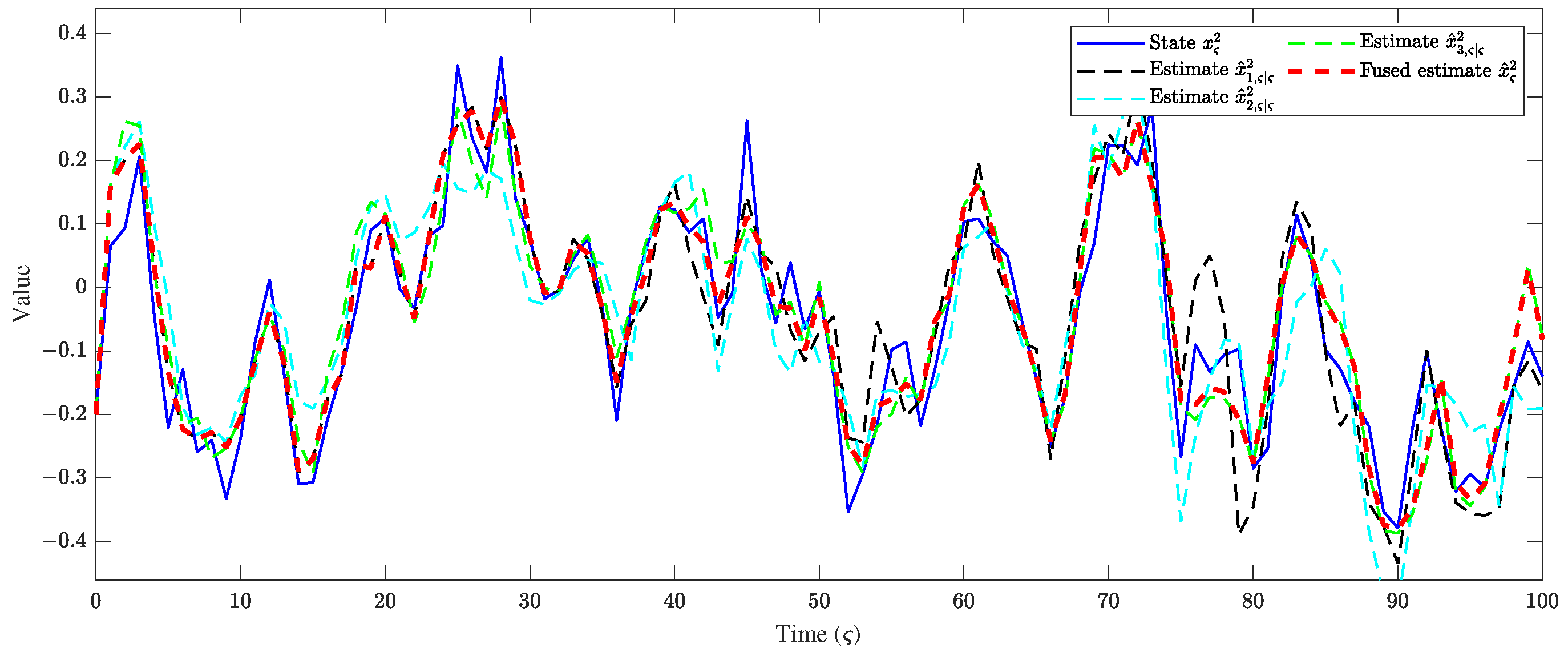
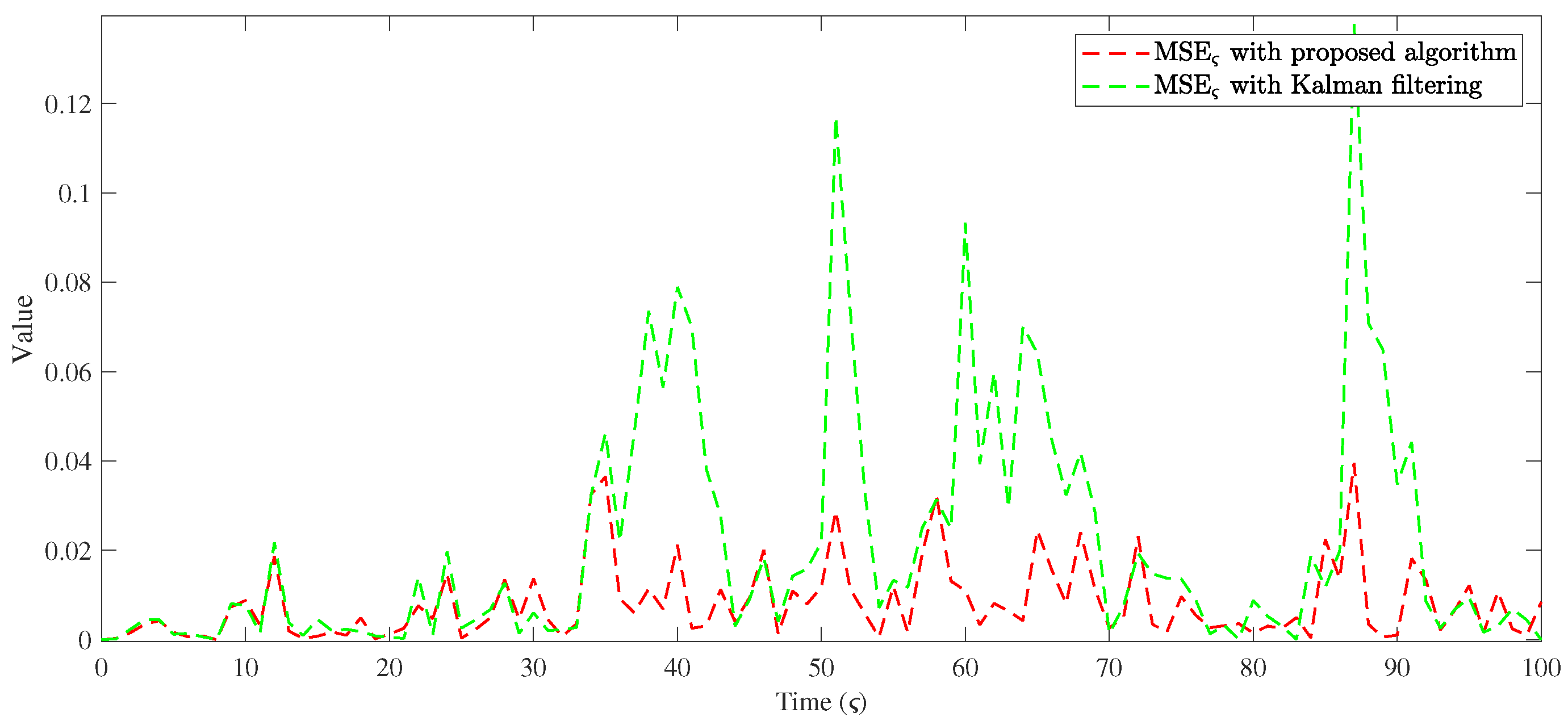
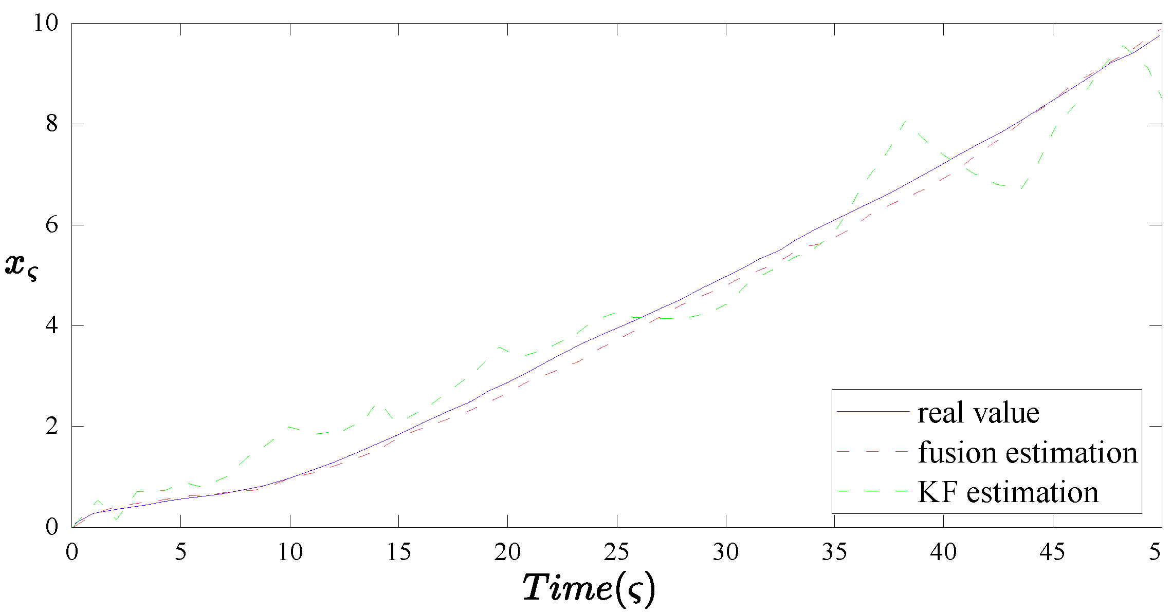
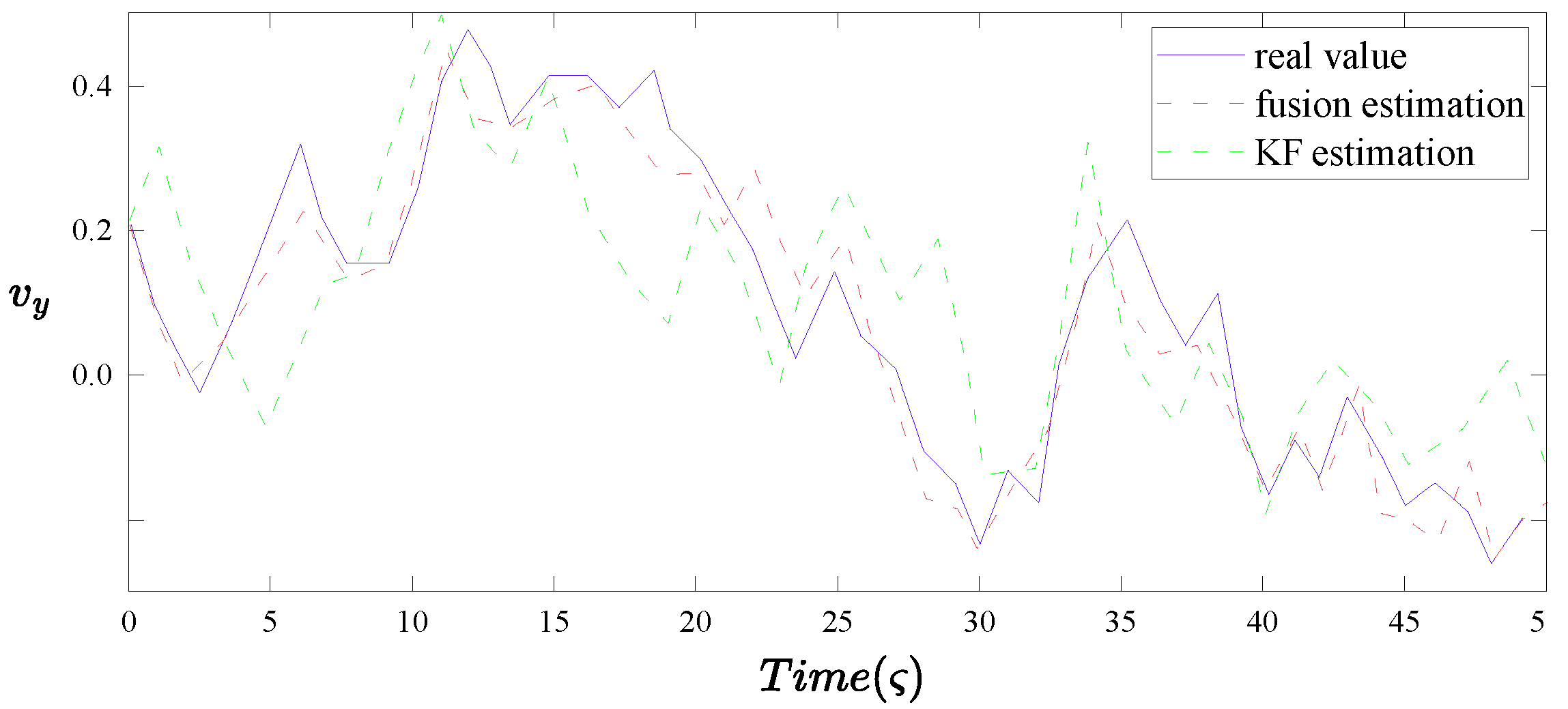
Finally, experimental results are provided to validate the effectiveness of the proposed recursive fusion state estimation strategy.
The structure of this paper is outlined as follows: In Section 2, a multi-sensor time-varying system including ROPUs, TCFCs, and DETM is constructed, and the corresponding local estimator is established. In Section 3, the recursive fusion state estimation algorithm is proposed, ensuring the convergence of the upper bound of the local EEC with the desired local estimator gains, and fusion estimates are obtained using CIFS at the fusion center. Section 4 presents simulation experiments to test the effectiveness of the proposed recursive fusion state estimation approach. Finally, Section 5 concludes this work. For ease of reference, a comprehensive symbol table is provided in the Appendix A.

2. Problem Formulation

Before presenting the system model and problem setup, we first introduce some notation used throughout this paper for clarity.
Notation: The notations applied in this paper are standard unless otherwise pointed out. R n x is the n-dimensional Euclidean space; I and 0 are, respectively, the identity matrix and zero matrix with compatible dimensions; M T , M 1 and tr { M } stand for the transposition, inverse, and trace of the matrix M, respectively; X > Y ( X Y ) represents that X Y is a positive definite (positive semi-definite) matrix for the symmetric matrices X and Y; Pr { } means the probability of event “∗” occurring; E { } is used to mean the mathematical expectation of the stochastic variable ⋆.
Figure 1 illustrates the proposed fusion state estimation framework for multi-sensor systems, which is divided into four functional modules: the sensor side, communication channel, node side, and fusion center.
The system is equipped with multiple sensors, each associated with a DETM. DETM is applied at the sensor side to regulate the frequency of data transmission, thereby alleviating communication burden while maintaining estimation performance. It adaptively determines whether to transmit the current measurement data based on predefined triggering conditions, effectively suppressing redundant communication.
Once the transmission is triggered, the measurement data are sent over TCFCs, which reflect realistic wireless communication scenarios. These channels exhibit temporal correlations in signal degradation caused by multipath propagation, path loss, and occlusion, posing significant challenges to reliable and timely data delivery.
At each node, a local estimator independently performs state estimation based on the received measurements. These estimators are designed to be robust against ROPUs, which may arise from environmental disturbances, structural changes, or sensor/component failures.
Finally, all local estimates are transmitted to the fusion center, where they are integrated through CIFS. This strategy ensures that the global state estimate remains consistent and accurate, enhancing the system’s robustness and fault tolerance under both modeling uncertainties and complex communication conditions.
The considered multi-sensor systems with randomly occurring parameter uncertainties are described by:
x ς + 1 = ( A ς + θ ς Δ A ς ) x ς + ϖ ς y i , ς = C i , ς x ς + D i , ς υ i , ς , i = 1 , 2 , , N
where x ς R n x stands for the system state and y i , ς R n y denotes the i-th sensor measurement output. A ς , C i , ς and D i , ς are the time-varying matrices with given dimensions. ϖ ς and υ i , ς , respectively, represent the zero-mean Gaussian white noise variables satisfying covariance R ς > 0 and W i , ς > 0 , which stand for the process noise and measurement noise. Meanwhile, the parameter uncertainties Δ A ς is a time-varying real-valued matrix satisfying the following condition:
Δ A ς = U ς V ς S ς ,
where U ς and S ς are time-varying matrices with known dimensions, V ς denotes the function of uncertainties which is an unknown time-varying matrix with the following constraint:
V ς V ς T I .
In addition, the Bernoulli distributed random variable θ ς is employed to characterize the occurrence of parameter uncertainties, which takes a value of 0 and 1 with the following probabilities:
Pr { θ ς = 1 } = θ ¯ Pr { θ ς = 0 } = 1 θ ¯
where θ ¯ [ 0 , 1 ] is a given constant.
For the purpose of energy-saving, DETM is conducted to regulate the frequency of transmissions. We define the triggering instants by 0 = l 0 < 1 < 2 < < l < l + 1 < , which is determined by
t l + 1 = min ς [ 0 , N ] | ς > t l , 1 ϖ i λ i , ς + γ i y i , ς .
Here, γ i and ϖ i are given positive scalars, y i , ς + 1 y i , ς + 1 y i , t l , y i , t l denotes the transmitted measurement at latest event time, dynamic variable λ i , ς satisfies the following relationship:
λ i , ς + 1 = ϰ i λ i , ς + γ i y i , ς
where ϰ i > 0 is a given scalar and λ 0 represents the initial value.
In conventional periodic transmission schemes, the measurement signals are regularly transmitted through TCFCs. Under such conditions, the received measurements can be modeled as:
z i , ς = ϱ i , ς y i ς + ε i , ς
where ε i , ς R is the channel noise which satisfies the Gaussian white noise sequence with mean E { ε i , ς } = 0 covariance E { ε i , ς ε i , ς T } = O i , ς > 0 . The i-th fading channel coefficient ϱ i , ς can be described by
ϱ i , ς + 1 = ξ i , ς ϱ i , ς + 1 ξ i , ς δ i , ς .
Here, ξ i , ς ( 0 , 1 ) represents the time-correlated factor and δ i , ς R denotes an independently Gaussian distributed stochastic variable with mean E { δ i , ς } = 0 covariance E { δ i , ς δ i , ς T } = Q i , ς > 0 .
However, in this paper, the measurement signals y i , t l are transmitted only at the triggering instants determined by DETM. Due to the irregular nature of such transmissions, the received signal under DETM also exhibits a temporal deviation. Accordingly, we define a channel-induced deviation term as ϵ i , ς z i , ς + 1 z i , t l , which captures the discrepancy between the newly received signal and the last successfully transmitted value under DETM.
Assumption 1.
All the mentioned noise signals ϖ ς , υ i , ς , ε i , ς and δ i , ς are supposed to be mutually independent.
Assumption 2.
The initial value x 0 and fading channel coefficient ϱ i , 0 with the means x ¯ 0 and ϱ ¯ i , 0 and covariances P 0 and q i , 0 are mutually independent and also uncorrelated with the above noise signals ϖ ς , υ i , ς , ε i , ς and δ i , ς .
By introducing ψ i , ς = ϱ i , ς x ς , it is followed from Equations (1) and (8) that
ψ i , ς + 1 = ξ i , ς ( A ς + θ ς Δ A ς ) ψ i , ς + ξ i , ς ϱ i , ς ϖ ς + 1 ξ i , ς δ i , ς ( A ς + θ ς Δ A ς ) x ς + 1 ξ i , ς δ i , ς ϖ ς .
Then, by setting η i , ς = [ x ς T ψ i , ς T ] T , the augmented model can be constructed from Equations (1) and (9) as follows
η i , ς + 1 = ( A 1 i , ς + θ ς Δ A 1 i , ς ) η i , ς + B 1 i , ς ϱ i , ς ϖ ς + ( A 2 i , ς + θ ς Δ A 2 i , ς ) δ i , ς x ς + B 2 i , ς δ i , ς ϖ ς z i , ς = C i , ς η i , ς + ϱ i , ς D i , ς υ i , ς + ε i , ς
where
A 1 i , ς = A ς 0 0 ξ i , ς A ς , Δ A 1 i , ς = Δ A ς 0 0 ξ i , ς Δ A ς , A 2 i , ς = 0 1 ξ i , ς A ς , Δ A 2 i , ς = 0 1 ξ i , ς Δ A ς , ϱ i , ς = I ϱ i , ς I , B 1 i , ς = I 0 0 ξ i , ς I , B 2 i , ς = 0 1 ξ i , ς I , C i , ς = 0 C i , ς .
For the augmented system Equation (10), we can construct the local estimator with the following expression
η ^ i , ς + 1 | ς = A 1 i , ς η ^ i , ς | ς η ^ i , ς + 1 | ς + 1 = η ^ i , ς + 1 | ς + K i , ς + 1 ( z i , t l + 1 C i , ς + 1 η ^ i , ς + 1 | ς )
where η ^ i , ς + 1 | ς and η ^ i , ς + 1 | ς + 1 denote the local one-step prediction and the local estimation of the augmented system state η i , ς + 1 . K i , ς + 1 stands for the i-th local estimator parameters to be designed.
Define the local one-step prediction and the local estimation error as η ˜ i , ς + 1 | ς η i , ς + 1 η ^ i , ς + 1 | ς and η ˜ i , ς + 1 | ς + 1 η i , ς + 1 η ^ i , ς + 1 | ς + 1 , respectively. Clearly, it can be obtained from Equations (10) and (11) that
η ˜ i , ς + 1 | ς = A 1 i , ς η ˜ i , ς | ς + θ ς Δ A 1 i , ς η i , ς + B 1 i , ς ϱ i , ς ϖ ς + ( A 2 i , ς + θ ς Δ A 2 i , ς ) δ i , ς x ς + B 2 i , ς δ i , ς ϖ ς η ˜ i , ς + 1 | ς + 1 = ( I K i , ς + 1 C i , ς + 1 ) η ˜ i , ς + 1 | ς ϱ i , ς + 1 K i , ς + 1 D i , ς + 1 υ i , ς + 1 K i , ς + 1 ε i , ς + 1 + K i , ς + 1 ϵ i , ς + 1
Then, we can define the local one-step prediction error covariance and the local EEC of the augmented system state η i , ς + 1 as Σ i , ς + 1 | ς and Σ i , ς + 1 | ς + 1 , respectively, which can be determined by the following forms
Σ i , ς + 1 | ς = E { η ˜ i , ς + 1 | ς η ˜ i , ς + 1 | ς T } , Σ i , ς + 1 | ς + 1 = E { η ˜ i , ς + 1 | ς + 1 η ˜ i , ς + 1 | ς + 1 T } .
Let x ^ i , ς | ς be the local estimate of state x ς from the i-th estimator and P i , ς | ς = E { ( x ς x ^ i , ς | ς ) ( x ς x ^ i , ς | ς ) T } be the corresponding EEC. In this paper, the main aim is to find the estimate x ^ i , ς | ς such that the upper bound P ¯ ς | ς on EEC P i , ς | ς is ensured, i.e., P i , ς | ς P ¯ ς | ς , where the estimation process is subject to the negative effects of TCFCs and ROPUs. Then, the estimator gain K i , ς is recursively designed to minimize the derived upper bound. Furthermore, the fusion of n local estimates of state x ς will be conducted to obtain the fused estimate.
Obviously, we can easily obtain x ^ i , ς | ς and P i , ς | ς with the help of the following equations
x ^ i , ς | ς = I 0 η ^ i , ς | ς P i , ς | ς = I 0 Σ i , ς | ς I 0
So that, our goals can be equivalent to deriving an upper bound Σ ¯ i , ς | ς on EEC Σ i , ς | ς , i.e., Σ i , ς | ς Σ ¯ ς | ς , and then the upper bound Σ ¯ i , ς | ς is minimized by selecting appropriate estimator gain K i , ς . Ultimately, CIFS is utilized to fuse all the local estimates of x ς .
Remark 1.
The purpose of this paper is to study the recursive fusion state estimation issue for multi-sensor systems with ROPUs and TCFCs. In order to overcome all challenges posed by ROPUs and TCFCs, we will present the following solutions: (1) A random variable obeying the Bernoulli stochastic distribution is used to denote the occurrence probability of parameter uncertainties, which is determined by norm-bounded unknown matrices. (2) Wireless channels that perform the function of transmitting signals are considered to face the challenge of time-correlated fading. Therefore, an auxiliary variable is employed to construct an augmented model reflecting the simultaneous dynamics of the fading coefficients and system states. (3) Due to the effects induced by ROPUs and TCFCs, it is impossible to calculate the precise EEC. As an alternative method, the minimum upper bound of the local EEC will be provided by parameterizing the estimator gain matrices.

3. Main Theoretical Results

In this part, we first derive an upper bound on EEC and then choose the appropriate estimator gain to obtain the minimal upper bound. Moreover, the fusion estimate is acquired by utilizing all of the local estimates. For the purpose of facilitating the derivation of our main results, we present the following lemmas.
Lemma 1
([40]). For two real vectors U and V , we can obtain the inequality as follows
U V T + V U T χ U U T + χ 1 V V T ,
where the positive scalar χ is arbitrary.
Lemma 2.
Setting ϱ ¯ i , ς + 1 = E { ϱ i , ς + 1 } and Π i , ς + 1 = E { ϱ i , ς + 1 ϱ i , ς + 1 T } , we can acquire the following relationships:
ϱ ¯ i , ς + 1 = ξ i , ς ϱ ¯ i , ς ,
and
Π i , ς + 1 = ξ i , ς Π i , ς + ( 1 ξ i , ς ) Q i , ς
with initial values satisfying E { ϱ i , 0 } = ϱ ¯ i , 0 and Π i , 0 = E { ϱ i , 0 ϱ i , 0 T } = ϱ ¯ i , 0 2 + q i , 0 .
Proof. 
The proof can be obtained directly by noting Equation (8), omitted here.    □
Lemma 3.
Defining X ς + 1 = E { x ς + 1 x ς + 1 T } . The state-space constraint Equation (1) yields
X ς + 1 X ¯ ς + 1
where X ¯ ς + 1 satisfies
X ¯ ς + 1 = ( 1 + θ ¯ α ς ) A ς X ς A ς T + ( θ ¯ + θ ¯ α ς 1 ) × tr { S ς X ς S ς T } U ς U ς T + R ς X ¯ 0 = x ¯ 0 x ¯ 0 T + P 0
Here, α ς is a positive scalar.
Proof. 
By noting Equation (1) and using Lemma 1, one has
X ς + 1 = E { x ς + 1 x ς + 1 T } = E { ( ( A ς + θ ς Δ A ς ) x ς + ϖ ς ) ( ( A ς + θ ς Δ A ς ) x ς + ϖ ς ) T } = E { ( A ς + θ ς Δ A ς ) x ς x ς T ( A ς + θ ς Δ A ς ) T } + R ς = E { A ς x ς x ς T A ς T + θ ¯ A ς x ς x ς T Δ A ς T + θ ¯ Δ A ς x ς x ς T A ς T + θ ¯ Δ A ς x ς x ς T Δ A ς T } + R ς ( 1 + θ ¯ α ς ) A ς E { x ς x ς T } A ς T + ( θ ¯ + θ ¯ α ς 1 ) Δ A ς E { x ς x ς T } Δ A ς T + R ς ( 1 + θ ¯ α ς ) A ς X ς A ς T + ( θ ¯ + θ ¯ α ς 1 ) ( U ς S ς V ς ) X ς ( U ς S ς V ς ) T + R ς ( 1 + θ ¯ α ς ) A ς X ς A ς T + ( θ ¯ + θ ¯ α ς 1 ) tr { S ς X ς S ς T } U ς U ς T + R ς .
Now, the proof of Lemma 3 is complete.    □
Lemma 4.
Suppose that the positive scalars c i , ς , d i , ς and e i , ς are given. A UB defined by Υ i , ς + 1 E { λ i , ς + 1 2 } is obtained by the following recursion:
Υ ¯ i , ς + 1 ( Υ ¯ i , ς ) = ( 1 + c i , ς ) ( 1 + d i , ς ) ϰ i 2 + ( 1 + c i , ς 1 ) ( 1 + e i , ς ) ϖ i 2 Υ ¯ i , ς + ( 1 + c i , ς ) ( 1 + d i , ς 1 ) + ( 1 + d i , ς 1 ) ( 1 + e i , ς 1 ) γ i 2
with initial value Υ ¯ i , 0 = λ i , 0 2 , where Υ ς Υ ¯ ς .

3.1. Design of Local Estimators

In what follows, we intend to derive the upper bound on the local EEC Σ i , ς | ς .
Theorem 1.
Suppose that the positive scalars β i , ς ( i = 1 , 2 , , N ) , a 1 , a 2 is known, if the matrices have the following recursions below:
Σ ¯ i , ς + 1 | ς ( 1 + θ ¯ β i , ς ) A 1 i , ς Σ ¯ i , ς | ς A 1 i , ς T + ( θ ¯ + θ ¯ β i , ς 1 ) A ˜ 1 i , ς + B 1 i , ς R ˜ i , ς B 1 i , ς T + A 2 i , ς Q i , ς X ς A 2 i , ς T + θ ¯ A ˜ 2 i , ς + B 2 i , ς Q i , ς R i , ς B 2 i , ς T ,
and
Σ ¯ i , ς + 1 | ς + 1 ( I K i , ς + 1 C i , ς + 1 ) Σ ¯ i , ς + 1 | ς ( I K i , ς + 1 C i , ς + 1 ) T + ( 1 + a i , 1 ) Π i , ς + 1 K i , ς + 1 D i , ς + 1 W i , ς + 1 D i , ς + 1 T K i , ς + 1 T + ( 1 + a i , 2 ) K i , ς + 1 O i , ς + 1 K i , ς + 1 T + ( ( 1 + a i , 1 1 + a i , 2 1 ) K i , ς + 1 ¯ ( Υ ¯ i , ς ) K i , ς + 1 T I
with Σ i , 0 | 0 Σ ¯ i , 0 | 0 , where
A ˜ 1 i , ς = tr { S ς X ς S ς T } U ς U ς T ξ i , ς ϱ ¯ i , ς tr { S ς X ς S ς T } U ς U ς T ξ i , ς ϱ ¯ i , ς tr { S ς X ς S ς T } U ς U ς T ξ i , ς Π i , ς tr { S ς X ς S ς T } U ς U ς T , A ˜ 2 i , ς = 0 0 0 ( 1 ξ i , ς ) Q i , ς tr { S ς X ς S ς T } U ς U ς T , R ˜ i , ς = R ς ϱ ¯ i , ς R ς ϱ ¯ i , ς R ς Π i , ς R ς ,
then Σ ¯ i , ς + 1 | ς + 1 is an upper bound on Σ i , ς + 1 | ς + 1 , i.e., Σ i , ς + 1 | ς + 1 Σ ¯ i , ς + 1 | ς + 1 .
Proof. 
Suppose that Σ i , ς | ς Σ ¯ i , ς | ς with the initial condition satisfying Σ i , 0 | 0 Σ ¯ i , 0 | 0 , then we just need to demonstrate that Σ i , ς + 1 | ς + 1 Σ ¯ i , ς + 1 | ς + 1 .
According to the statistical properties of the Gaussian white noises, it follows from Equations (12) and (13) that
Σ i , ς + 1 | ς = E { η ˜ i , ς + 1 | ς η ˜ i , ς + 1 | ς T } = E { A 1 i , ς η ˜ i , ς | ς η ˜ i , ς | ς T A 1 i , ς T + A 1 i , ς η ˜ i , ς | ς ( θ ς Δ A 1 i , ς η i , ς ) T + θ ς Δ A 1 i , ς η i , ς ( A 1 i , ς η ˜ i , ς | ς ) T + ( θ ς Δ A 1 i , ς η i , ς ) ( θ ς Δ A 1 i , ς η i , ς ) T + B 1 i , ς ϱ i , ς ϖ ς ϖ ς T ϱ i , ς T B 1 i , ς T + A 2 i , ς δ i , ς x ς x ς T δ i , ς T A 2 i , ς T + θ ς Δ A 2 i , ς δ i , ς x ς x ς T δ i , ς T ( θ ς Δ A 2 i , ς ) T + B 2 i , ς δ i , ς ϖ ς ϖ ς T δ i , ς T B 2 i , ς T } .
By using Lemma 1 again, Equation (23) can be further rewritten as
Σ i , ς + 1 | ς ( 1 + θ ¯ β i , ς ) A 1 i , ς Σ i , ς | ς A 1 i , ς T + ( θ ¯ + θ ¯ β i , ς 1 ) E { Δ A 1 i , ς η i , ς η i , ς T Δ A 1 i , ς T } + B 1 i , ς E { ϱ i , ς ϖ ς ϖ ς T ϱ i , ς T } B 1 i , ς T + A 2 i , ς Q i , ς X ς A 2 i , ς T + θ ¯ E { Δ A 2 i , ς δ i , ς x ς x ς T δ i , ς T Δ A 2 i , ς T } + B 2 i , ς Q i , ς R i , ς B 2 i , ς T .
Considering the characteristics of Δ A 1 i , ς , Δ A 2 i , ς , ϖ ς and δ i , ς , it is not difficult to deduce that
E { Δ A 1 i , ς η i , ς η i , ς T Δ A 1 i , ς T } = E { Δ A ς x ς x ς T Δ A ς T } E { ξ i , ς Δ A ς x ς η i , ς T Δ A ς T } E { ξ i , ς Δ A ς η i , ς x ς T Δ A ς T } ξ i , ς Δ A ς η i , ς η i , ς T Δ A ς T tr { S ς X ς S ς T } U ς U ς T ξ i , ς ϱ ¯ i , ς tr { S ς X ς S ς T } U ς U ς T ξ i , ς ϱ ¯ i , ς tr { S ς X ς S ς T } U ς U ς T ξ i , ς Π i , ς tr { S ς X ς S ς T } U ς U ς T A ˜ 1 i , ς ,
E { Δ A 2 i , ς δ i , ς x ς x ς T δ i , ς T Δ A 2 i , ς T } = 0 0 0 E { ( 1 ξ i , ς ) Δ A ς δ i , ς x ς x ς T δ i , ς T Δ A ς T } 0 0 0 ( 1 ξ i , ς ) Q i , ς tr { S ς X ς S ς T } U ς U ς T A ˜ 2 i , ς ,
E { ϱ i , ς ϖ ς ϖ ς T ϱ i , ς T } = E { ϖ ς ϖ ς T } E { ϱ i , ς ϖ ς ϖ ς T } E { ϱ i , ς ϖ ς ϖ ς T } E { ϱ i , ς ϖ ς ϖ ς T ϱ i , ς T } = R ς ϱ ¯ i , ς R ς ϱ ¯ i , ς R ς Π i , ς R ς R ˜ i , ς .
By substituting Equations (25) and (26) to Equation (24), we have
Σ i , ς + 1 | ς ( 1 + θ ¯ β i , ς ) A 1 i , ς Σ i , ς | ς A 1 i , ς T + ( θ ¯ + θ ¯ β i , ς 1 ) A ˜ 1 i , ς + B 1 i , ς R ˜ i , ς B 1 i , ς T + A 2 i , ς Q i , ς X ς A 2 i , ς T + θ ¯ A ˜ 2 i , ς + B 2 i , ς Q i , ς R i , ς B 2 i , ς T .
Owning to Σ i , ς | ς Σ ¯ i , ς | ς , it yields that
Σ i , ς + 1 | ς ( 1 + θ ¯ β i , ς ) A 1 i , ς Σ ¯ i , ς | ς A 1 i , ς T + ( θ ¯ + θ ¯ β i , ς 1 ) A ˜ 1 i , ς + B 1 i , ς R ˜ i , ς B 1 i , ς T + A 2 i , ς Q i , ς X ς A 2 i , ς T + θ ¯ A ˜ 2 i , ς + B 2 i , ς Q i , ς R i , ς B 2 i , ς T .
Therefore, we can obtain that Σ i , ς + 1 | ς Σ ¯ i , ς + 1 | ς . On the other hand, we intend to demonstrate that Σ i , ς + 1 | ς + 1 Σ ¯ i , ς + 1 | ς + 1 . Noting Equations (12) and (13) again, Σ i , ς + 1 | ς + 1 can be calculated as follows
Σ i , ς + 1 | ς + 1 = E { η ˜ i , ς + 1 | ς + 1 η ˜ i , ς + 1 | ς + 1 T } = E { ( I K i , ς + 1 C i , ς + 1 ) η ˜ i , ς + 1 | ς η ˜ i , ς + 1 | ς T ( I K i , ς + 1 C i , ς + 1 ) T + ϱ i , ς + 1 K i , ς + 1 D i , ς + 1 υ i , ς + 1 υ i , ς + 1 T D i , ς + 1 T K i , ς + 1 T ϱ i , ς + 1 + K i , ς + 1 ε i , ς + 1 ε i , ς + 1 T K i , ς + 1 T + K i , ς + 1 ϵ i , ς + 1 ϵ i , ς + 1 T K i , ς + 1 T + ϱ i , ς + 1 K i , ς + 1 D i , ς + 1 υ i , ς + 1 ϵ i , ς + 1 T K i , ς + 1 T + K i , ς + 1 ϵ i , ς + 1 υ i , ς + 1 T D i , ς + 1 T K i , ς + 1 T ϱ i , ς + 1 + K i , ς + 1 ε i , ς + 1 ϵ i , ς + 1 T K i , ς + 1 T + K i , ς + 1 ϵ i , ς + 1 ε i , ς + 1 T K i , ς + 1 T } .
Using the Lemma 1, we can obtain that
ϱ i , ς + 1 K i , ς + 1 D i , ς + 1 υ i , ς + 1 ϵ i , ς + 1 T K i , ς + 1 T + K i , ς + 1 ϵ i , ς + 1 υ i , ς + 1 T D i , ς + 1 T K i , ς + 1 T ϱ i , ς + 1 a i , 1 ϱ i , ς + 1 K i , ς + 1 D i , ς + 1 υ i , ς + 1 υ i , ς + 1 T D i , ς + 1 T K i , ς + 1 T ϱ i , ς + 1 + a i , 1 1 K i , ς + 1 ϵ i , ς + 1 ϵ i , ς + 1 T K i , ς + 1 T ,
K i , ς + 1 ε i , ς + 1 ϵ i , ς + 1 T K i , ς + 1 T + K i , ς + 1 ϵ i , ς + 1 ε i , ς + 1 T K i , ς + 1 T a i , 2 K i , ς + 1 ε i , ς + 1 ε i , ς + 1 T K i , ς + 1 T + a i , 2 1 K i , ς + 1 ϵ i , ς + 1 ϵ i , ς + 1 T K i , ς + 1 T ,
from which, the last term on the right side is computed as
E { ϵ i , ς + 1 ϵ i , ς + 1 T } E { ϵ i , ς + 1 T ϵ i , ς + 1 I } E { ( 1 ϖ i λ i , ς + γ i ) ( ( 1 ϖ i λ i , ς + γ i ) T } 1 + κ i λ i , ς 2 Υ ¯ ς + ( 1 + κ i 1 ) γ i 2 I ¯ ( Υ ¯ i , ς ) .
where κ is known, and noting Lemma 4, which leads to E { ϵ i , ς + 1 ϵ i , ς + 1 T } ¯ ( Υ ¯ i , ς ) .
Based on Σ i , ς + 1 | ς Σ ¯ i , ς + 1 | ς , it follows from Equations (30)–(33) that
Σ i , ς + 1 | ς + 1 ( I K i , ς + 1 C i , ς + 1 ) Σ ¯ i , ς + 1 | ς ( I K i , ς + 1 C i , ς + 1 ) T + ( 1 + a i , 1 ) Π i , ς + 1 K i , ς + 1 D i , ς + 1 W i , ς + 1 D i , ς + 1 T K i , ς + 1 T + ( 1 + a i , 2 ) K i , ς + 1 O i , ς + 1 K i , ς + 1 T + ( ( 1 + a i , 1 1 + a i , 2 1 ) K i , ς + 1 ¯ ( Υ ¯ i , ς ) K i , ς + 1 T I .
Up to now, we have proved that Σ i , ς + 1 | ς + 1 Σ ¯ i , ς + 1 | ς + 1 , which has finished the proof of Theorem 1.    □
So that, by noting Equation (14), we can obtain that P ¯ i , k | k = I 0 Σ ¯ i , ς | ς I 0 > P i , ς | ς , which means P ¯ i , ς | ς is the upper bound on P i , ς | ς , i.e., P i , ς | ς P ¯ i , ς | ς .
Subsequently, the theorem will parameterize the estimator gain matrices through the minimization of the upper bound Σ ¯ i , ς + 1 | ς + 1 on EEC.
Theorem 2.
The upper bound Σ ¯ i , ς + 1 | ς + 1 at each time step can be minimized by utilizing the following estimator gain matrix
K i , ς + 1 = Σ ¯ i , ς + 1 | ς C i , ς + 1 T Ξ i , ς + 1 1
where
Ξ i , ς + 1 = C i , ς + 1 Σ ¯ i , ς + 1 | ς C i , ς + 1 T + ( 1 + a i , 1 ) Π i , ς + 1 D i , ς + 1 W i , ς + 1 D i , ς + 1 T + ( 1 + a 2 , i ) O i , ς + 1 + ( ( 1 + a i , 1 1 + a i , 2 1 ) ¯ ( Υ ¯ i , ς ) I .
Moreover, the minimum upper bound Σ ¯ i , ς + 1 | ς + 1 on EEC Σ i , ς + 1 | ς + 1 is determined by the following form
Σ ¯ i , ς + 1 | ς + 1 = Σ ¯ i , ς + 1 | ς Σ ¯ i , ς + 1 | ς C i , ς + 1 Ξ i , ς + 1 1 C i , ς + 1 T Σ ¯ i , ς + 1 | ς .
where Σ ¯ i , ς + 1 | ς is given in Equation (21).
Proof. 
It is followed from Equation (22) that the upper bound Σ ¯ i , ς + 1 | ς + 1 can be further written as
Σ ¯ i , ς + 1 | ς + 1 = ( I K i , ς + 1 C i , ς + 1 ) Σ ¯ i , ς + 1 | ς ( I K i , ς + 1 C i , ς + 1 ) T + ( 1 + a i , 1 ) Π i , ς + 1 K i , ς + 1 D i , ς + 1 W i , ς + 1 D i , ς + 1 T K i , ς + 1 T + ( 1 + a i , 2 ) K i , ς + 1 O i , ς + 1 K i , ς + 1 T + ( ( 1 + a i , 1 1 + a i , 2 1 ) K i , ς + 1 ¯ ( Υ ¯ i , ς ) K i , ς + 1 T I = ( K i , ς + 1 Σ ¯ i , ς + 1 | ς C i , ς + 1 T Ξ i , ς + 1 1 ) Ξ i , ς + 1 ( K i , ς + 1 Σ ¯ i , ς + 1 | ς C i , ς + 1 T Ξ i , ς + 1 1 ) T Σ ¯ i , ς + 1 | ς C i , ς + 1 Ξ i , ς + 1 1 C i , ς + 1 T Σ ¯ i , ς + 1 | ς + Σ ¯ i , ς + 1 | ς .
It should be noted that Ξ i , k + 1 > 0 . By choosing the estimator gain matrix K i , ς + 1 = Σ ¯ i , ς + 1 | ς C i , ς + 1 T Ξ i , ς + 1 1 in Equation (38), we can easily obtain the minimum upper bound Σ ¯ i , ς + 1 | ς + 1 , which is determined by Equation (37). The proof for Theorem 2 is now concluded.    □

3.2. Fusion of Local Estimates

In the next content, all the local estimates x ¯ i , k | k of x ς are fused through the fusion estimator to achieve the fused estimate by using CIFS, which can be specifically described as follows
x ^ ς = P ¯ ς i = 1 N μ i , ς P ¯ i , ς | ς 1 x ^ i , ς | ς , P ¯ ς = ( i = 1 N μ i , ς P ¯ i , ς | ς 1 ) 1 ,
where x ^ k and P ¯ k represent the fused estimate and its corresponding fusion estimation covariance, respectively. μ i , ς 0 ( i = 1 , 2 , , N ) stands for the weights, which can be deduced by tackling the optimization problem below:
min P = min { tr { P ¯ ς } } , s . t . i = 1 N μ i , ς = 1 , μ i , ς 0 .
Remark 2.
In Theorem 1 and 2, the issue of the fusion state estimation process has been dealt with for multi-sensor systems under ROPUs and TCFCs. Specifically, by means of mathematical induction, we have calculated the upper bound on EEC, which is an important performance index for the designed local estimator. In Theorem 2, the appropriate estimator gains have been computed such that the upper bound on EEC derived in Theorem 1 is minimized. Furthermore, all the local estimates are employed to acquire the fusion estimates by applying CIFS. In recent years, the multi-sensor fusion estimation problem has attracted significant research attention in the control field, and various strategies have been proposed. Compared with existing literature developed for the fusion estimation problems, the unique and innovative aspects of this paper are outlined below: (1) the parameter uncertainties with random occurrence characteristics are considered in multi-sensor systems; (2) a novel approach is exploited by using an auxiliary variable to characterize the dynamics of the system state and channel coefficients; (3) the recursive fusion state estimation problem is first addressed in the multi-sensor systems considering ROPUs and TCFCs.
Up to now, the design of recursive fusion state estimation for multi-sensor systems subject to ROPUs and TCFCs has been completed, whose specific procedure is summarized in Algorithm 1. In the following part, we will indicate the usefulness of the developed fusion state estimation strategy.
Algorithm 1 The recursive fusion state estimation algorithm.
  1:
Initialization: Set ς = 0 and the runtime as T. For node i, the initial values x ¯ 0 , P 0 , ϱ ¯ i , 0 , q i , 0 and the positive scalar α ς , β i , ς are given.
  2:
         for  ς = 1 : T  do
  3:
            Calculate the estimator gain K i , ς according to (35);
  4:
            Calculate the estimate η ^ i , ς | ς for state η ς from (12);
  5:
            Compute the upper bound Σ ¯ i , ς | ς on EEC for state η ς based on (22);
  6:
            Generated the estimate x ^ i , ς | ς for state x ς with x ^ i , ς | ς = [ I 0 ] η ^ i , ς | ς ;
  7:
            Generated the upper bound P ¯ i , ς | ς on EEC for state x ς with P i , ς | ς = [ I 0 ] Σ ¯ i , ς | ς [ I 0 ] T ;
  8:
            Obtain the fused estimate x ^ ς and its corresponding EEC for state x ς via (39);
  9:
         end for
10:
Until End of the simulation time.

4. Simulation Experiments

This section presents two illustrative examples to demonstrate the effectiveness of the proposed filtering scheme.

4.1. Numerical Example

4.1.1. Parameters and Enevironment Setting

In the experiments presented in this paper, we have provided a detailed configuration of the parameters for the multi-sensor system to facilitate performance evaluation in subsequent simulations. Table 1 presents the system model parameters and noise covariance matrices. Table 2 lists the observation matrices and communication parameters, as well as the initial states and time-varying factors of each node. Finally, Table 3 summarizes the settings related to the DETM and other relevant parameters. The following sections will be based on these settings to conduct performance analysis and result discussions.
To analyze the performance of the fusion state estimation scheme, the mean square error (MSE) is expressed as follows
M S E i , ς 1 300 t = 1 300 j = 1 2 ( x ς j x ^ i , ς | ς j ) ( x ς j x ^ i , ς | ς j ) T , i = 1 , 2 , 3
where x ς j and x ^ i , ς | ς j represent the j-th elements of the actual state and its corresponding i-th estimator’s estimates, respectively.
The experiments were conducted in MATLAB R2023b, running on a CPU with Intel Core i7-9700K processor and 16GB of RAM. The system was simulated using a multi-sensor configuration, where three sensors (Sensor 1, Sensor 2, and Sensor 3) were used to provide state estimates based on their respective measurements. The simulation environment was designed to evaluate the performance of the proposed fusion state estimation strategy under various challenging conditions, such as time-correlated channel fading and random parameter uncertainties.
The simulation procedure was as follows:
1.
System Setup: The system was modeled as a time-varying state-space system, with state vectors denoted as x ς 1 and x ς 2 , which were estimated by three local sensors. The system dynamics were defined based on a nominal system matrix A ς and a time-varying uncertain matrix Δ A ς to simulate uncertainties.
2.
DETM: To reduce the communication burden, DETM was applied. This mechanism adjusts the transmission frequency based on the system’s estimation accuracy and the triggering threshold γ i , leading to reduced communication overhead while maintaining the estimation performance.
3.
Channel Fading Simulation: The transmission between nodes was subject to time-correlated fading channels, modeled using multiplicative fading factors ϱ i , ς . The fading coefficients were simulated based on a Markovian process, and Gaussian noise δ i , ς was introduced to influence the fading dynamics.
4.
Fusion of Local Estimates: The local state estimates from each sensor were fused at a central fusion center using the recursive fusion state estimation algorithm. The fusion was performed using CIFS, where the fusion estimator used the local estimates and their associated covariance matrices to obtain a global state estimate x ^ ς .

4.1.2. Experimental Results

Based on the above parameters and the environment setting, the experimental results are listed in Figure 2, Figure 3, Figure 4, Figure 5, Figure 6 and Figure 7. To be specific, Figure 2 indicates the actual state and its estimates for x ς 1 , where the solid blue line indicates the actual state x ς 1 , the black, cyan, green and red dashed lines stand for the estimates of sensor 1, 2, 3 and the fusion estimate, respectively. The actual state and its estimates for x k 2 are plotted in Figure 3, where the solid blue line represents the actual state x ς 2 , the black, cyan, green, and red dashed lines stand for the estimates of sensor 1, 2, 3 and the fusion estimate, respectively. Figure 4 depicts the trace of the minimum upper bound P ¯ i , k | k ( i = 1 , 2 , 3 ) and MSEs of each estimate for x ς , where the solid blue line denotes the upper bound, and the red dashed line denotes its corresponding MSE. In Figure 5, the trace of the upper bounds P ¯ i , ς | ς and P ¯ ς are presented, where the black, cyan, green, and red dashed lines are, respectively, the trace of upper bound P ¯ 1 , ς | ς , P ¯ 2 , ς | ς , P ¯ 3 , ς | ς and P ¯ ς . In Figure 6, it can be observed that under the DETM, the transmission frequency of each local estimator is significantly reduced, while the state estimation accuracy remains high. Additionally, the curves of the fading channel coefficients are plotted in Figure 7.
According to the above experimental results, it is obvious that (1) the proposed fusion state estimation strategy performs well, where the negative impacts of time-correlated channel fading challenge and random parameter uncertainties have been solved properly; (2) the upper bounds are always higher than the corresponding MSEs, which is consistent with our theoretical results; (3) the trace of the fusion upper bound is always lower than the local upper bounds, which confirms that our proposed fusion scheme has stable and effective estimation performance.

4.1.3. Comparison Against Kalman Filtering

To verify the superiority of our work, the designed fusion estimation algorithm is compared with Kalman filtering in terms of the estimation performance. The parameters are the same with Section 4.1. The comparison results are shown in Figure 8, Figure 9 and Figure 10 and Table 4. In Figure 8, the actual state and its estimates for x ς 1 are plotted, where the solid blue line represents the actual state x ς 1 , the red and green dashed lines indicate the estimates based on the proposed algorithm and Kalman filtering, respectively. Figure 9 displays the actual state and its estimates for x ς 2 , where the solid blue line represents the actual state x ς 1 , the red and green dashed lines indicate the estimates based on the proposed algorithm and Kalman filtering, respectively. The curves of MSEs are plotted in Figure 10, where the red and green dashed lines denote the values of MSEs with the proposed algorithm and Kalman filtering. In addition, to demonstrate the performance more clearly, the root-mean-square errors (RMSEs) of estimation based on the proposed algorithm and Kalman filtering are calculated in Table 4. Obviously, the values of RMSEs for the proposed algorithm and Kalman filtering are 0.81 % and 2.09 % , respectively, and their corresponding iteration time for each time step are 0.046 ms and 0.029 ms, which means that the proposed algorithm achieves 58 % improvement in accuracy while only increasing 32.4 % computation time. Overall, the simulation experiments have illustrated the feasibility and usefulness of our proposed fusion state estimation scheme.

4.2. Autonomous Vehicle

According to the formulation in [26,41], The motion of the autonomous vehicle in a 2D plane can be characterized by its positions and velocities along the x and y axes, denoted by x ς , y ς and v x , ς , v y , ς , respectively. The terms a x , ς and a y , ς represent acceleration-related disturbances in each direction. The time step between updates is denoted by t. The kinematic behavior of an autonomous vehicle is described by:
v x , ς + 1 = v x , ς + a x , ς · t v y , ς + 1 = v y , ς + a y , ς · t x ς + 1 = x ς + v x , ς · t + 1 2 a x , ς · t 2 y ς + 1 = y ς + v y , ς · t + 1 2 a y , ς · t 2
Letting X ς = [ x ς , y ς , v x , ς , v y , ς ] T and considering parameter uncertainties caused by the uneven road and the tire friction, the following uncertain system can be obtained:
X ς + 1 = ( A ς + Δ A ς ) X ς + ϖ ς
where
A ς = 1 0 t 0 0 1 0 t 0 0 1 0 0 0 0 1 , ϖ ς = B a ˜ ς , Δ A ς = U ς V ς S ς a ˜ ς = a x , ς a y , ς , B = t 2 2 0 0 t 2 2 t 0 0 t , t = 0.2 s , S ς = 0.01 I 4 U ς = 0.005 0 0.001 0 0 0.003 0 0.002 0 0 0.01 0 0 0 0 0.02 V ς = 0.05 sin ( ς ) 0 t 0 0 0.002 cos ( ς ) 0 t 0 0 0.01 sin ( ς ) 0 0 0 0 0.002 cos ( ς )
Moreover, the stochastic noises satisfy that E { a ˜ ς a ˜ ς T } = 0.03 I 2 and E { υ i , ς υ i , ς T } = 0.00002 I 2 . The statistical characters of the initial value are X 0 = [ 0 0 0.2 0.2 ] T and P 0 = 0.01 I 4 .
x ς and y ς of the autonomous vehicle are measured by the onboard camera installed at the vehicle’s center of gravity. In addition, a GNSS receiver provides absolute position measurements. Considering stochastic measurement noise in both sensors, the measurement vectors at time ς are denoted as follows:
y i , ς = C i , ς x ς + D i , ς υ i , ς
where
y i , ς = x i , ς y i , ς , C i , ς = 1 0 0 0 0 1 0 0 , D i , ς = 1 1
The visual data captured by the camera and the position measurements from the GNSS receiver are sent to the remote estimator via a wireless communication link. Due to signal reflections caused by surrounding structures and the inherent memory characteristics of the wireless channel, the transmitted data is affected by time-correlated fading. The fading effect impacts both the visual data and GNSS measurements. The parameters for the fading channel are selected as ξ 1 , ς = 0.98 , ξ 2 , ς = 0.97 , ϱ 1 , 0 = ϱ 2 , 0 = 0.9 , O i , ς = 0.001 I and Q i , ς = 0.01 I . In addition, the parameters about DETM are set as γ 1 = 0.03 , γ 2 = 0.02 , ϰ 1 = ϰ 2 = 0.1 , α ς = 1 , and other parameters are a i , 1 = a i , 2 = κ i = 1 , c i , ς = d i , ς = e i , ς = 1 , θ ¯ = 0.9 .
Based on the parameter settings described above, the proposed dynamic event-triggered fusion estimation algorithm is applied to the state estimation task of an autonomous vehicle. Its performance is evaluated in comparison with the conventional Kalman Filter to assess estimation accuracy, robustness, and computational efficiency.
Figure 11 and Figure 12 show the estimated displacements of the vehicle along the x-axis and y-axis, respectively. The results demonstrate that the proposed method more closely tracks the ground truth trajectory, with significantly smaller estimation deviations. This highlights its superior performance in multi-sensor data fusion under complex environmental conditions.
Figure 13 and Figure 14 present the velocity estimation results along the x-axis and y-axis. Compared with the conventional Kalman Filter, the proposed method yields smoother and more accurate velocity profiles, particularly during rapid changes in speed and in the presence of measurement noise. The method shows strong tracking capability across both steady and dynamic motion phases, confirming its robustness in uncertain and time-varying scenarios.
Table 5 provides a quantitative comparison between the two methods in terms of RMSE and average iteration time. The proposed algorithm achieves an RMSE of 0.93%, a substantial improvement over the Kalman Filter’s RMSE of 2.65%, representing a 64.9% relative reduction in estimation error. Although the iteration time increases slightly from 0.032 ms (Kalman Filter) to 0.054 ms, the computational load remains well within acceptable limits for real-time execution, making the algorithm practical for deployment on embedded systems.
To evaluate performance under realistic network conditions, Figure 15 depicts the evolution of fading channel coefficients ϱ 1 , ς and ϱ 2 , ς over 50 time steps. Both coefficients start from 0.9 and generally exhibit a declining trend due to channel degradation. Between time steps 40 and 45, a mild recovery is observed, with final values of 0.54 for ϱ 1 , ς and 0.43 for ϱ 2 , ς . These correlated, time-varying patterns mimic real-world wireless fading effects such as multipath interference and urban shadowing, validating the necessity of incorporating fading models into the estimator design.
Figure 16 illustrates the triggering moments of two sensor nodes under the DETM. Within a 50-step time horizon, Trigger 1 and Trigger 2 are activated only 32 and 38 times, respectively, corresponding to reductions of 18 and 12 transmissions compared to periodic sampling (50 triggers each). This represents communication savings of 36% and 24%, respectively, demonstrating that the DETM effectively reduces network load without compromising estimation quality.
Finally, Figure 17 shows the temporal evolution of the dynamic triggering variable λ i , ς , which reflects each node’s local decision-making dynamics. The variable adjusts adaptively to changes in system state and channel quality, guiding the triggering condition in real time. This behavior illustrates the responsiveness and efficiency of the proposed scheme in balancing estimation accuracy with communication resource usage. Overall, the results affirm the practical potential of the proposed method for resource-constrained autonomous systems operating in unreliable network environments.

5. Conclusions

This paper investigates the recursive fusion state estimation problem for multi-sensor systems affected by TCFCs and ROPUs, incorporating a dynamic event-triggered mechanism to optimize data transmission and state estimation performance. The parameter uncertainties are described by a random variable following a Bernoulli stochastic distribution, while sensor measurements are transmitted to their corresponding local estimators through TCFCs and event-triggered transmission. To comprehensively characterize the dynamic effects of system states, channel fading properties, and the event-triggering mechanism, an augmented state model is constructed. Based on mathematical induction, a local state estimation algorithm is designed to ensure the convergence of the upper bound of the local EEC and minimize it through adaptive adjustment of the local estimator gains. Moreover, a CIFS is employed to integrate the local estimates from multiple estimators, further enhancing the global estimation accuracy. Finally, simulation experiments demonstrate that the proposed recursive fusion state estimation algorithm improves estimation accuracy by 58% while increasing computational time by only 32.4%. Additionally, the dynamic event-triggered mechanism effectively reduces communication frequency by 36.7%, exhibiting superior robustness and resource efficiency compared to the conventional Kalman filtering approach.

Author Contributions

Conceptualization: C.H.; Methodology: C.H.; Software: T.Z.; Validation: T.Z. and Y.C.; Formal analysis: T.Z.; Investigation: T.Z., Y.C. and H.C.; Resources: Y.C.; Data curation: T.Z.; Visualization: T.Z.; Writing—original draft: T.Z.; Writing—review & editing: T.Z. and C.H.; Supervision: C.H., Q.S. and H.C.; Project administration: C.H. and H.C.; Funding acquisition: C.H. and Q.S. All authors have read and agreed to the published version of the manuscript.

Funding

This work was supported in part by the National Natural Science Foundation of China under Grant 62403259, the Natural Science Foundation of Jiangsu Province under Grant BK20240945, and the 333 Talent Technology Research Project of Jiangsu under Grants 2022021, the Postgraduate Research & Practice Innovation Program of the School of Transportation and Civil Engineering, Nantong University under Grant NTUJTXYGI2303, and the Postgraduate Research & Practice Innovation Program of Jiangsu Province under Grant KYCX243637.

Institutional Review Board Statement

Not applicable.

Informed Consent Statement

Not applicable.

Data Availability Statement

Data are contained within the article.

Conflicts of Interest

The authors declare no conflicts of interest.

Appendix A

To facilitate the understanding of the mathematical derivations and notation used throughout the paper, this appendix provides a comprehensive list of symbols and their corresponding meanings. Unless otherwise stated, all variables are assumed to be time-varying and their subscripts indicate time step or node index as appropriate.
Table A1. Symbol Table.
SymbolMeaning
x ς System state at time ς
A ς Nominal system matrix at time ς
θ ς modeling uncertainty
Δ A ς Time-varying uncertain matrix
U ς , V ς , S ς Matrix decomposition components of Δ A ς
ϖ ς Process noise at time ς
y i , ς Measurement of node i at time ς
C i , ς Measurement matrix of node i
D i , ς Measurement noise matrix of node i
υ i , ς Measurement noise of node i at time ς
z i , ς Measurement received by node i after disturbance
ϱ i , ς Multiplicative fading factor for node i
ε i , ς Additive disturbance in the measurement transmission
ξ i , ς Markovian parameter governing fading process
δ i , ς Gaussian noise influencing fading process
t l Latest event-triggering time
γ i Triggering threshold for node i
ϖ i Triggering scaling factor
ϵ i , ς Difference between current and last transmitted measurement
λ i , ς Dynamic variable used in event-triggering condition
ϰ i Weighting factor in λ recursion
η ^ i , ς + 1 | ς Prior estimate of extended state at node i
η ^ i , ς + 1 | ς + 1 Posterior estimate of extended state at node i
A 1 i , ς Augmented system matrix
C i , ς + 1 Augmented measurement matrix
K i , ς + 1 Kalman gain at time ς + 1 for node i
Σ i , ς + 1 | ς Prior error covariance matrix
Σ i , ς + 1 | ς + 1 Posterior error covariance matrix
Σ ¯ i , ς | ς Upper bound of the estimation error covariance
ϱ ¯ i , ς Expected value of fading factor
Π i , ς Second moment of fading factor ϱ i , ς
Q i , ς Covariance matrix of δ i , ς
q i , 0 Initial variance of fading factor
c i , ς , d i , ς , e i , ς Positive scalars for upper-bound derivation
Υ i , ς Squared expectation of λ i , ς
Υ ¯ i , ς Upper bound of Υ i , ς
( · ) Recursive function for updating Υ ¯ i , ς
x ^ ς Global state estimate of the fusion estimator at time ς
P ¯ ς Covariance matrix of the fusion estimate
μ i , ς Fusion weight coefficient, satisfying i = 1 N μ i , ς = 1 , μ i , ς 0
NTotal number of nodes
P Objective function to be minimized

References

  1. Kianoush, S.; Savazzi, S.; Rampa, V.; Costa, L.; Tolochenko, D. A random forest approach to body motion detection: Multisensory fusion and edge processing. IEEE Sens. J. 2023, 23, 3801–3814. [Google Scholar] [CrossRef]
  2. Lu, Z.; Rao, W.; Wu, Y.; Guo, L.; Xia, J. A Kalman filter approach to dynamic od flow estimation for urban road networks using multi-sensor data. J. Adv. Transp. 2015, 49, 210–227. [Google Scholar] [CrossRef]
  3. Yang, H.; Zhang, Y.; Gu, W.; Yan, H.; Yang, F. A novel global set-membership filtering approach for localization of automatic guided vehicles. IEEE Trans. Ind. Inform. 2023, 19, 3219–3228. [Google Scholar] [CrossRef]
  4. Hu, Z.; Hu, J.; Tan, H.; Huang, J.; Cao, Z. Distributed resilient fusion filtering for nonlinear systems with random sensor delay under round-robin protocol. Int. J. Syst. Sci. 2022, 53, 2786–2799. [Google Scholar] [CrossRef]
  5. Zhao, L.; Cao, X.; Li, L.; Yang, H. Event-triggered distributed fusion for multirate multisensor systems with heavy-tailed noises. IEEE Trans. Syst. Man Cybern. Syst. 2022, 52, 3137–3150. [Google Scholar] [CrossRef]
  6. Shen, B.; Wang, Z.; Tan, H.; Chen, H. Robust fusion filtering over multisensor systems with energy harvesting constraints. Automatica 2021, 131, 109782. [Google Scholar] [CrossRef]
  7. Lin, H.; Lu, S.; Lu, P.; Que, H.; Sun, P. Centralized fusion estimation over wireless sensor-actuator networks with unobservable packet dropouts. J. Frankl. Inst. 2022, 359, 1569–1584. [Google Scholar] [CrossRef]
  8. Gao, X.; Chen, J.; Tao, D.; Li, X. Multi-sensor centralized fusion without measurement noise covariance by variational bayesian approximation. IEEE Trans. Aerosp. Electron. Syst. 2011, 47, 718–272. [Google Scholar] [CrossRef]
  9. Fernández-Alcalá, R.M.; Navarro-Moreno, J.; Ruiz-Molina, J.C. T-proper hypercomplex centralized fusion estimation for randomly multiple sensor delays systems with correlated noises. Sensors 2021, 21, 5729. [Google Scholar] [CrossRef]
  10. Sun, S.; Lin, H.; Ma, J.; Li, X. Multi-sensor distributed fusion estimation with applications in networked systems: A review paper. Inf. Fusion 2017, 38, 122–134. [Google Scholar] [CrossRef]
  11. Liu, Y.; Wang, Z.; Lin, H.; Ma, L.; Lu, G. Encoding–decoding-based fusion estimation with filter-and-forward relays and stochastic measurement delays. Inf. Fusion 2023, 100, 101963. [Google Scholar] [CrossRef]
  12. Zhao, Z.; Wang, Z.; Zou, L.; Liu, H.; Alsaadi, F.E. Zonotopic multi-sensor fusion estimation with mixed delays under try-once-discard protocol: A set-membership framework. Inf. Fusion 2023, 91, 681–693. [Google Scholar] [CrossRef]
  13. Kaneba, C.M.; Mu, X.; Li, X.; Wu, X. Event triggered control for fault tolerant control system with actuator failure and randomly occurring parameter uncertainty. Appl. Math. Comput. 2022, 415, 126714. [Google Scholar] [CrossRef]
  14. Liu, Y.M.; Fang, F.; Zhou, J.; Liu, Y.J. H state estimation for T-S fuzzy reaction-diffusion delayed neural networks with randomly occurring gain uncertainties and semi-Markov jump parameters. Neurocomputing 2022, 493, 385–396. [Google Scholar] [CrossRef]
  15. Zhang, S.; Wang, Z.; Ding, D.; Shu, H. Fuzzy filtering with randomly occurring parameter uncertainties, interval delays, and channel fadings. IEEE Trans. Cybern. 2014, 44, 406–417. [Google Scholar] [CrossRef]
  16. Wang, S.; Fang, H.; Tian, X. Event-based robust state estimator for linear time-varying system with uncertain observations and randomly occurring uncertainties. J. Frankl. Inst. 2017, 354, 1403–1420. [Google Scholar] [CrossRef]
  17. Zhu, L.; Huang, C.; Shi, Q.; Gao, R.; Ping, P. A joint state and fault estimation scheme for state-saturated system with energy harvesting sensors. Sensors 2024, 24, 1967. [Google Scholar] [CrossRef]
  18. Li, J.; Zhang, B.; Lu, R.; Xu, Y. Robust distributed H state estimation for stochastic periodic systems over constraint sensor networks. IEEE Trans. Syst. Man Cybern. Syst. 2020, 50, 4396–4407. [Google Scholar] [CrossRef]
  19. Hua, M.; Zhang, L.; Yao, F.; Ni, J.; Dai, W.; Cheng, Y. Robust H filtering for continuous-time nonhomogeneous Markov jump nonlinear systems with randomly occurring uncertainties. Signal Process. 2018, 148, 250–259. [Google Scholar] [CrossRef]
  20. Su, T.; Wang, Z.; Zou, L.; Alsaadi, F.E. Maximum-correntropy-based Kalman filtering for time-varying systems with randomly occurring uncertainties: An event-triggered approach. Int. J. Robust Nonlinear Control. 2021, 31, 1582–1599. [Google Scholar] [CrossRef]
  21. Shen, Y.; Sun, S. Distributed recursive filtering for multi-rate uniform sampling systems with packet losses in sensor networks. Int. J. Syst. Sci. 2023, 54, 1729–1745. [Google Scholar] [CrossRef]
  22. Zang, G.; Shi, S.; Ma, Y. Dynamic event-triggered synchronisation control for complex dynamical networks with stochastic attacks and actuator faults. Int. J. Syst. Sci. 2023, 54, 1755–1773. [Google Scholar] [CrossRef]
  23. Khudonogova, L.I.; Muravyov, S.V. Interval data fusion with preference aggregation for balancing measurement accuracy and energy consumption in WSN. Wirel. Pers. Commun. 2021, 118, 2399–2421. [Google Scholar] [CrossRef]
  24. Sun, J.; Shen, B.; Zou, L. Ultimately bounded state estimation for nonlinear networked systems with constrained average bit rate: A buffer-aided strategy. IEEE Trans. Signal Process. 2024, 72, 1865–1876. [Google Scholar] [CrossRef]
  25. Shen, Y.; Wang, Z.; Shen, B.; Alsaadi, F.E. Event-based recursive filtering for a class of nonlinear stochastic parameter systems over fading channels. Int. J. Gen. Syst. 2018, 47, 401–415. [Google Scholar] [CrossRef]
  26. Tan, H.; Shen, B.; Shu, H. Robust recursive filtering for stochastic systems with time-correlated fading channels. IEEE Trans. Syst. Man Cybern. Syst. 2022, 52, 3102–3112. [Google Scholar] [CrossRef]
  27. Han, F.; Wang, Z.; Dong, H.; Yi, X.; Alsaadi, F.E. Recursive distributed filtering for time-varying systems over sensor network via rayleigh fading channels: Tackling binary measurements. IEEE Trans. Signal Inf. Process. Over Netw. 2023, 9, 110–122. [Google Scholar] [CrossRef]
  28. Tang, M.; Liu, M.; Zhang, S.; Zheng, R.; Dong, S. Distributed target tracking with fading channels over underwater acoustic sensor networks. IEEE Internet Things J. 2024, 11, 13980–13994. [Google Scholar] [CrossRef]
  29. Qu, H.; Yang, F. Distributed H-consensus filtering for target state tracking over a wireless filter network with switching topology, channel fading and packet dropouts. Neurocomputing 2020, 400, 401–411. [Google Scholar] [CrossRef]
  30. Liu, W.; Shi, P. Optimal linear filtering for networked control systems with time-correlated fading channels. Automatica 2019, 101, 345–353. [Google Scholar] [CrossRef]
  31. Cheng, H.; Shen, B.; Sun, J. Distributed fusion filtering for multi-sensor systems under time-correlated fading channels and energy harvesters. J. Frankl. Inst. 2023, 360, 6021–6039. [Google Scholar] [CrossRef]
  32. Li, Q.; Wang, Z.; Shen, B.; Liu, H.; Sheng, W. A resilient approach to recursive distributed filtering for multirate systems over sensor networks with time-correlated fading channels. IEEE Trans. Signal Inf. Process. Over Netw. 2021, 7, 636–647. [Google Scholar] [CrossRef]
  33. Wang, S.; Wang, Z.; Dong, H.; Chen, Y.; Alsaadi, F.E. Recursive quadratic filtering for linear discrete non-gaussian systems over time-correlated fading channels. IEEE Trans. Signal Process. 2022, 70, 3343–3356. [Google Scholar] [CrossRef]
  34. Li, Q.; Wang, Z.; Dong, H.; Sheng, W. Recursive filtering for complex networks with time-correlated fading channels: An outlier-resistant approach. Inf. Sci. 2022, 615, 348–367. [Google Scholar] [CrossRef]
  35. Ding, S.; Wang, Z.; Xie, X. Periodic event-triggered synchronization for discrete-time complex dynamical networks. IEEE Trans. Neural Netw. Learn. Syst. 2021, 33, 3622–3633. [Google Scholar] [CrossRef]
  36. Li, B.; Wang, Z.; Ma, L. An event-triggered pinning control approach to synchronization of discrete-time stochastic complex dynamical networks. IEEE Trans. Neural Netw. Learn. Syst. 2018, 29, 5812–5822. [Google Scholar] [CrossRef]
  37. Huang, C.; Zhao, T.; Mei, P.; Yang, D.; Shi, Q. Dynamic event-triggering joint state and unknown input estimation for nonlinear systems with random sensor failure. IEEE Sens. J. 2023, 23, 29415–29424. [Google Scholar] [CrossRef]
  38. Fei, Y.; Zhang, D.; Sun, Y.; Shi, P. Dynamically Triggered Estimator-Based Controller and Its Application on an Omnidirectional Robot. IEEE Trans. Autom. Sci. Eng. 2024, 21, 3921–3932. [Google Scholar] [CrossRef]
  39. Chen, J.; Tian, Y.; Zhang, G.; Cao, Z.; Zhu, L.; Shi, D. IoT-Enabled Intelligent Dynamic Risk Assessment of Acute Mountain Sickness: The Role of Event-Triggered Signal Processing. IEEE Trans. Ind. Inform. 2023, 19, 730–738. [Google Scholar] [CrossRef]
  40. Hu, J.; Wang, Z.; Gao, H.; Stergioulas, L.K. Stergioulas, Extended kalman filtering with stochastic nonlinearities and multiple missing measurements. Automatica 2012, 48, 2007–2015. [Google Scholar] [CrossRef]
  41. Le Cadre, J.-P.; Tremois, O. Bearings-only tracking for maneuvering sources. IEEE Trans. Aerosp. Electron. Syst. 1998, 34, 179–193. [Google Scholar] [CrossRef]
Figure 1. The fusion state estimation framework over multi-sensor network.
Electronics 14 02211 g001
Figure 2. State x ς 1 and its estimates.
Electronics 14 02211 g002
Figure 3. State x ς 2 and its estimates.
Electronics 14 02211 g003
Figure 4. The trace of the upper bounds and their corresponding MSEs.
Electronics 14 02211 g004
Figure 5. The trace of the upper bounds.
Electronics 14 02211 g005
Figure 6. Triggering moments of different DETM.
Electronics 14 02211 g006
Figure 7. The trajectories of fading channel coefficients.
Electronics 14 02211 g007
Figure 8. State x ς 1 and its estimates.
Electronics 14 02211 g008
Figure 9. State x ς 2 and its estimates.
Electronics 14 02211 g009
Figure 10. MSEs with different estimation algorithms.
Electronics 14 02211 g010
Figure 11. Estimation comparison of displacement in the x direction.
Electronics 14 02211 g011
Figure 12. Estimation comparison of displacement in the y direction.
Electronics 14 02211 g012
Figure 13. Estimation comparison of velocity in the x direction.
Electronics 14 02211 g013
Figure 14. Estimation comparison of velocity in the y direction.
Electronics 14 02211 g014
Figure 15. The trajectories of fading channel coefficients.
Electronics 14 02211 g015
Figure 16. Triggering moments of different DETM.
Electronics 14 02211 g016
Figure 17. Time evolution of the triggering dynamic variable λ i , ς .
Electronics 14 02211 g017
Table 1. System matrices and noise covariances.
ParameterExpression/ValueLocation
A ς 0.79 0.25 cos ( ς ) 1 0.2 sin ( ς ) 0.42 Equation (1)
U ς 0.3 sin ( ς ) 0 0 0.2 cos ( 2 ς ) Equation (2)
V ς 0.01 sin ( ς ) 0 0 0.01 cos ( ς ) Equation (2)
S ς 0.2 sin ( 2 ς ) 0 0 0.3 cos ( ς ) Equation (2)
R ς 0.005 I The covariance of ϖ ς in Equation (1)
W i , ς 0.002 I The covariance of υ i , ς in Equation (1)
O i , ς 0.04 I The covariance of ε i , ς in Equation (7)
Q i , ς 0.008 I The covariance of δ i , ς in Equation (8)
Table 2. Node observation matrices and communication parameters.
Node i C i , ς D i , ς ξ i , ς ϱ ¯ i , 0
1 [ 3 4 ] 0.250.971
2 [ 3 2 ] 0.250.981
3 [ 2 3 ] 0.250.991
Table 3. Other parameter settings.
ParameterValueLocation
θ ¯ 0.9Equation (4)
x 0 [ 0.3 0.2 ] T Initial state
P 0 0.05 I Initial covariance matrix
ϖ i 10Equation (5)
γ i 0.2Equation (5)
ϰ i 0.1Equation (6)
α ς 1Equation (18)
β i , ς 1Theorem. 1
a i , 1 , a i , 2 , κ i 1Equation (36)
c i , ς , d i , ς , e i , ς 1Lemma 4
Table 4. Performance comparison between the proposed algorithm and Kalman filtering.
RMSE(%)Iteration Time (ms)
Proposed algorithm 0.81 0.046
Kalman filtering 2.09 0.029
Table 5. Performance comparison between the proposed algorithm and Kalman filtering.
RMSE (%)Iteration Time (ms)
Proposed algorithm 0.93 0.054
Kalman filtering 2.65 0.032
Disclaimer/Publisher’s Note: The statements, opinions and data contained in all publications are solely those of the individual author(s) and contributor(s) and not of MDPI and/or the editor(s). MDPI and/or the editor(s) disclaim responsibility for any injury to people or property resulting from any ideas, methods, instructions or products referred to in the content.

