Abstract
In recent years, many chaos-based encryption algorithms have been proposed. Many of these are based on established designs and populate their S-boxes with values derived from chaotic maps, following conventional implementation strategies to enable comparison with their original non-chaotic counterparts. In contrast, this work proposes a novel approach: a Chaos-Based Substitution Box (CB-SBox) implementation, in which conventional ROM-based S-boxes are replaced by a digital circuit that directly executes a selected chaotic map. This method enables the construction of S-boxes with long word lengths through an FPGA-based programmable circuit that allows for variable S-box lengths, facilitating the analysis of S-boxes of varying sizes, and ultimately enhancing security, particularly for larger S-boxes, as demonstrated by increased resistance to linear and differential cryptanalysis. Furthermore, the proposed CB-SBox achieves reductions in both area and power consumption compared to size-comparable ROM-based S-boxes. A 19-bit chaos-based S-box consumes just 0.0238% of the area and 0.0241% of the power required by an equivalent ROM-implemented S-box while providing the same level of security. The inherent unpredictability of non-linear chaotic behavior causes the proposed chaos-based S-boxes to exhibit non-bijective characteristics, making them well suited for application in non-invertible cryptographic primitives, such as hash functions and Feistel networks. The proposed CB-SBox is implemented in a Feistel network as described in the literature, and the results are provided.
1. Introduction
Since Lorenz’s 1963 seminal article [1], more than forty non-linear differential equations presenting chaotic behavior have been reported [2,3,4,5,6,7]. They have been applied to many disciplines, such as mechanics, biology, ecology, astronomy, and cryptography [8,9,10,11,12,13,14,15,16,17,18,19,20,21,22,23,24,25,26,27,28,29,30,31,32,33,34,35,36,37,38,39,40,41,42,43,44,45,46,47].
Chaos and encryption are intimately tied: confusion and diffusion, two fundamental concepts of cryptography [48], are strongly related to the chaotic properties of ergodicity and sensitivity to initial conditions [49]. The sensitivity to initial conditions ensures that even minimal changes in input, such as slight variations in the secret key, produce significantly different outputs, enhancing key sensitivity and resistance to differential attacks. The property of ergodicity allows chaotic maps to eventually cover the entire state space, contributing to the statistical uniformity of encrypted outputs and increasing resilience against cryptanalysis. Although deterministic, chaotic maps exhibit highly complex dynamics, resulting in outputs that appear random and providing a desirable balance between reproducibility and unpredictability. This complexity reinforces confusion, while the topological mixing characteristic of chaos facilitates effective diffusion, ensuring that small changes in plaintext or key propagate throughout the ciphertext. These features make chaos an attractive and powerful foundation for the design of robust cryptographic systems.
This relation led many researchers to develop chaos-based encryption algorithms: Shujun Li et al. [8] mixed stream and block cipher techniques in a real-time scheme that applied a cascade of chaotic maps. Tenny et al. [9] presented a public key encryption scheme based on additive chaos. Bose [10] created a novel compression and encryption scheme based on coupled chaos. Zou [11] proposed a new method to strengthen the non-linear kinetic complexity and ergodicity of the Lorenz system, generating output sequences applicable to chaotic image encryption with good security and a high capacity to resist common attacks. Khan [12] integrated Gold sequences with chaotic maps in an SP-network, achieving high-dimensional cryptographic robustness. Feng et al. [13] proposed, in 2021, an image transmission scheme based on two chaotic maps, divided into two parts: secure image transmission between sensor nodes and sink nodes, and secure image transmission between sensor nodes and receivers. In 2023, they introduced a new fractional-order 3D Lorenz chaotic map and a hyperchaotic map [14], both applied to a multi-image encryption algorithm characterized by excellent practicability, high security, and efficiency. In 2024, they constructed a robust hyperchaotic map [15] and further developed an efficient image encryption algorithm based on this map and a pixel fusion strategy. Later that same year, they proposed a novel multi-channel image encryption algorithm [16] that leveraged pixel reorganization and two hyperchaotic maps to jointly generate chaotic sequences with a larger key space and improved randomness. Ma et al. [17] proposed a digital image encryption scheme based on the Tabu Search algorithm and Chen’s hyperchaotic map, in which the encryption key and the initial values of the hyperchaotic map were derived from the plain image. Qian et al. [18] presented the design of a novel 2D polynomial hyperchaotic map, constructed by leveraging the cross-coupling of two titanium dioxide () memristors (non-linear circuit elements capable of retaining memory of past electrical states), and subsequently applied it to a multi-channel image encryption algorithm, demonstrating high security and notable efficiency. Yu et al. [19] proposed a new fractional-order memristive Hopfield neural network that exhibited rich dynamic behaviors, including transient chaos, which was implemented on a Field-Programmable Gate Array (FPGA), providing a theoretical basis for its application in encryption.
Many of these developed chaos-based encryption algorithms use chaos for constructing or populating tables and S-boxes: for Baptista’s non-bijective algorithm [20], a table was built, where each plaintext symbol was associated with the number of iterations performed on a chaotic logistic map to move the cipher key-dependent chaotic attractor’s initial state to a final state corresponding to the plaintext symbol. Wong et al. [21] presented embedding compression in the Baptista-type scheme [20], which was further improved by Chen et al. [22] through dynamic look-up table updating. The ciphertext in the scheme by Alvarez et al. [23] is a triplet composed of , a given threshold U, and a parameter B used by the transmitter to locate the plaintext on a binary chain C constructed according to the threshold U. Wong [24] improved Baptista’s cipher [20] by dynamically updating the look-up table that assigned plaintext to the corresponding attractor regions. Wong’s cipher was further improved [25,26,27,28] by methods that used control parameters and hashing schemes. Zhang [29] proposed a dynamic S-box generation algorithm using a hyperchaotic map and quantum random walks, evaluating its security against cryptographic attacks. Jakimoski et al. [30] proposed a procedure for designing chaos-based block ciphers built on a Feistel network with 8-bit bijective S-boxes, which were precomputed prior to the encryption process using a four-step algorithm based on the iteration of the logistic map. Peng [31] introduced a method for dynamically updating key-dependent S-boxes using a four-dimensional hyperchaotic Lorenz map to enhance the resistance of the encryption process. Guesmi [32] designed chaos-based S-boxes optimized with genetic algorithms, selecting the strongest ones through cryptographic criteria. Tang [33] proposed a dynamic S-box creation method based on discretized chaotic maps, improving resistance against cryptanalysis. Ibrahim [34] presented a 12-bit chaotic encryption scheme with a dynamic S-box optimized for grayscale medical images. Al-Maadeed [35] developed an image encryption algorithm integrating chaotic Lorenz sequences and algebraic S-boxes, ensuring robust diffusion and substitution. Ahmad [36] introduced an improved chaotic map for secure S-box generation, validated through cryptographic performance metrics. Nazir [37] exploited the 4D-hyperchaotic map to create three S-boxes (red, green, and blue) and used a logistic map to transform a plain image into DNA strands for enhanced color image encryption, demonstrating strong security properties. Manzoor [38] formulated a new chaotic S-box for block ciphers, leveraging a hybrid logistic–sine map with high Lyapunov exponents. Alabduallah [39] constructed an S-box based on Delannoy numbers and a five-dimensional hyperchaotic map, ensuring strong cryptographic characteristics. Goswami [40] implemented an FPGA-optimized SNOW 3G stream cipher with logic-gate-based S-boxes, improving efficiency. Lidong [41] developed a multi-image encryption scheme integrating chaotic maps, S-boxes, and image compression techniques. Jun [42] introduced a dynamic encryption step and extended the S-box size for improved image security. Ibrahim [43] proposed a generic medical image encryption framework using dynamic S-boxes and chaotic maps, validated through extensive security analysis. Zhang and Pasalic [44] proposed two methods for constructing highly non-linear and asymmetric S-boxes that could not be bijective. Piret et al. [45] proposed a new block cipher, PICARO, which was resistant to side-channel attacks and based on a Feistel network due to the use of a non-bijective S-box. Jassim and Farhan [46] proposed a new method for generating an 8-bit S-box using three integrated chaotic maps and the Flower Pollination Algorithm, in which bijectivity was guaranteed offline by randomly replacing repeated chaotic outputs. Zhu et al. [47] proposed an efficient and simple S-box generation method using a new compound chaotic map, the Sine–Tent one, and then introduced a new image encryption scheme based on double S-boxes.
In parallel, some studies investigated the conditions for applying chaos theory in encryption. The behavior of chaotic maps is highly sensitive to variations in initial conditions (IC), and in some cases, chaotic behavior may even vanish for specific IC values, causing the map to either converge to a fixed point or diverge away from the attractor. Dutra et al. [50] characterized the region of ICs responsible for driving the elementary chaotic map proposed by Linz and Sprott [7] into chaotic behavior and associated this region with the key space calculation of chaotic ciphers. Building upon these concepts, a new methodology [51] was proposed for evaluating and ranking chaotic maps suitable for cryptographic applications. The chaotic behavior of natural chaotic maps is also highly sensitive to quantization errors introduced by fixed-point arithmetic. Shujun [52,53,54,55] proposed several measurable dynamic indicators to quantitatively assess the degradation of piecewise chaotic maps when implemented with finite precision (fixed-point arithmetic).
The main contribution of this work is to propose an S-box implementation in which traditional Look-Up Table (LUT) structures, such as those presented in [20,21,22,23,24,25,26,27,28,29,30,31,32,33,34,35,36,37,38,39,40,41,42,43,44,45,46,47], are replaced by an on-the-fly fixed-point arithmetic calculation of a non-linear differential equation. This structure is referred to as a Chaos-Based Substitution Box (CB-SBox) and offers notable advantages in terms of area, power consumption, and cryptographic strength. Its temporal evolution drives the initial state , also referred to as the initial condition (IC), toward a deterministically linked yet uncorrelated final state . The final state is reached after executing the chaotic map for a fixed number of iterations. To the best of the authors’ knowledge, this is the first attempt to design a chaotic S-box based on this on-the-fly approach.
The rest of this work is organized as follows: Section 2 discusses the fixed-point arithmetic implementation of six non-linear differential chaotic maps. The evaluation method proposed in [51] is applied to select a chaotic map suitable for a Chaos-Based Substitution Box. In Section 3, the chosen map is used to construct a Chaos-Based Substitution Box (CB-SBox) circuit. This construction allows the final state of the selected differential chaotic map (the circuit output) to be obtained by feeding an initial condition into the circuit’s input. Section 4 compares the properties of the proposed CB-SBox with a typical memory-based LUT implementation. For a fair comparison, both implementations are carried out on an ASIC (Application-Specific Integrated Circuit) using VHDL (VHSIC Hardware Description Language). Parameters such as power, area, and time are analyzed in this section. The security improvements are evaluated by measuring resistance to differential and linear cryptanalysis [56]. Based on the proposed CB-SBox and the design decisions from the previous sections, Section 5 presents an application of the CB-SBox in a Feistel network block cipher from [30]. Finally, Section 6 concludes the article by summarizing the results and providing a glimpse of future work.
2. Chaotic Map Evaluation
The S-box proposed in this work is referred to as the Chaos-Based Substitution Box (CB-SBox). Its core is the fixed-point implementation of a non-linear differential system exhibiting chaotic behavior. Since Lorenz’s seminal 1963 paper [1], more than forty such maps have been reported [2,3,4,5,6,7]. From this collection, six maps were selected and evaluated using the method proposed in [51], with the objective of identifying the most suitable candidate for the CB-SBox design. The evaluation set was limited to six maps due to the significant computational effort required to simulate the evolving states driven by different initial conditions (ICs) across the allowable state space. Notably, the evaluation included the Sprott N map instead of the Sprott A, which demonstrated poor Attractor Density () values [51], and the plate 39 configuration was retained for Chua’s map.
The evaluation method described in [51] tracks four quantitative parameters (see Table 1): Attractor Density (), Largest Subset Volume (), Distance-to-Time Ratio (DTR), and Maximum Dispersion Time (MDT). The first parameter, Attractor Density (), directly reflects the spatial distribution of a strange attractor [57]—the set of states in the state space of a chaotic map. Low values of indicate that the chaotic map has poor dispersive capability over the state space, which is typically undesirable in applications such as chaotic encryption, where performance relies on the butterfly effect [58]. Let be the smallest axis-aligned bounding parallelepiped that contains the attractor set , and suppose it is partitioned into smaller parallelepiped volumes . Let denote the volume function. If k of these sub-volumes contain at least one point of , then the Attractor Density is calculated as follows in Equation (1):

Table 1.
Performance comparison of six selected chaotic maps according to the four-parameter evaluation method proposed in [51].
The second parameter, obtained from [51], the Largest Subset Volume (), is the subset volume that can be extracted from (volume of initial conditions—the three-dimensional volume containing all ICs capable of originating a strange attractor as shown in Figure 1). Let be the cardinality function, let denote the complement operation between sets, let ∪ be the union operator, let be the set of ICs belonging to the state space, let be the set of all possible attractors of a chaotic map, and let and be, respectively, the subsets of degenerated attractors that converge to a pole and those that diverge to infinity, both belonging to . Then, the set of strange attractors is defined as , and the is defined by Equation (2):
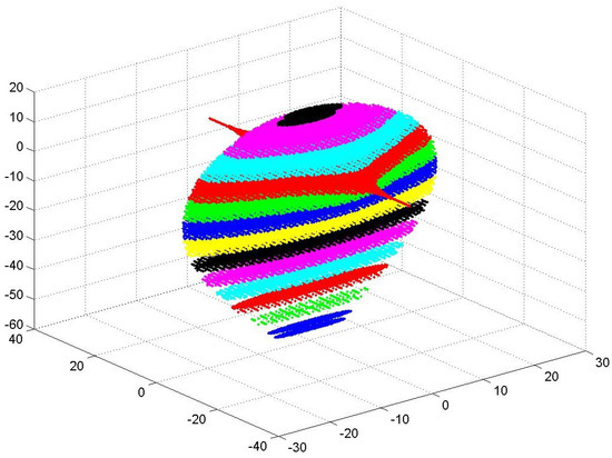
Figure 1.
Three-dimensional volume of valid initial conditions (), computed for the Sprott B chaotic map [5], adapted from [50], and made available online in [59] to support three-dimensional visualization.
The of each chaotic system has an irregular shape, which is difficult to represent analytically, and is best visualized graphically (see Figure 1). To overcome this intractability, the Largest Subset Volume () is defined as the volume of the largest parallelepiped entirely contained within . Unlike , the has tractable orthogonal boundaries, making it suitable for microelectronic realizations. This subset can provide a sufficient number of ICs for a wide range of applications. The use of ICs not belonging to leads to degenerate attractors ( or ), which weakens chaotic maps realizations by making the map’s future states predictable—an undesired effect, especially in encryption applications. Let be the function that measures the maximum variation of a given variable, and let , , and represent the three dimensions of the largest parallelepiped within . Then, the volume is calculated by Equation (3):
The third parameter, obtained from [51], Distance-to-Time Ratio (DTR), deals with the dispersion of the chaotic output states over . Let be a normalized metric with representing a complete dispersion, let n be the number of dimensions of a chaotic map, let m be the number of output bins of a histogram function, let be the m-set histogram bins measured for dimension n, and let and be the minimum and mean function, respectively. Then, can be calculated by the product of Equation (4):
Because of the butterfly effect [58], given a set of ICs and considering the minimum distance between neighboring ICs, after some time, the corresponding final states disperse over beyond a given threshold measured by . Smaller distances require more time to achieve this dispersion, leading to a negative ratio between and time. Let be a given dispersion threshold, let denote the mean function, let represent the temporal derivative of a given function, and let be the function that relates the minimum distance between successive ICs to the time necessary for their outputs to spread beyond the threshold. Then, the evaluation parameter DTR can be calculated by Equation (5). The reader should note that smaller absolute values of DTR imply that, for the same distance between successive ICs, less time is needed to disperse the state outputs over , which is a desirable property for chaotic systems:
The fourth parameter, obtained from [51], Maximum Dispersion Time (MDT), also deals with the dispersion of the chaotic output states over . Let be a given dispersion threshold, let be the function that measures a maximum peak value, and let be the function that relates the minimum distance between successive ICs to the time necessary to spread the outputs over , beyond the dispersion threshold. Then, the evaluation parameter MDT can be calculated by Equation (6):
The MDT parameter represents an upper bound concerning the time necessary to disperse the output states of a given chaotic map, which does not depend on the distance between successive ICs. Observe that the distance is directly related to the Discretization Criterion adopted by the microelectronic implementation of a given chaotic map.
After calculating the four parameters , , DTR, and MDT discussed in this section, we obtain the data presented in Table 1. Note that the best choice considering the Attractor Density () is Sprott B, which exhibits the strongest ergodicity among the analyzed maps. Regarding , the best option would be Sprott N, as it presents a larger parallelepiped volume containing the valid initial conditions (). The Distance-to-Time Ratio (DTR) presents negative values as expected. Sprott B is the best choice for this parameter, as it has the smallest absolute values of DTR, implying that, for the same distance between successive ICs, less time is required to disperse the state outputs over . Finally, the Maximum Dispersion Time (MDT) shows that the best choice regarding this criterion is also Sprott B, which disperses its outputs over the fastest. For the final conclusion, the grades in Table 1 are normalized, with the best score set to 1. A final score is calculated based on a set of four weights , defined as . The weighted average grade is shown in the last column of Table 1. The evaluation method ultimately allows for the selection of the highest-scoring map, Sprott B as highlighted in Table 1, making it the most suitable for the intended application.
Discrepancies can be observed, as expected, when comparing the grades obtained in the present work (Table 1), which are derived from a fixed-point arithmetic implementation, with those reported in [51], which are based on floating-point arithmetic. Among the four evaluation parameters presented in Table 1, is the least affected by the transition from floating-point to fixed-point arithmetic, as the volume of undergoes negligible variation in both implementations. On the other hand, the parameter is significantly constrained by the fixed-point implementation since the size and shape of are altered due to the accumulation of quantization errors in both the ICs and the intermediate states of . Quantization errors also affect the trajectory of the intermediate states within , resulting in differences in the calculated DTR and MDT values.
Both floating-point and fixed-point arithmetic implementations are approximations of real chaotic maps found in nature. The digitization of natural chaotic systems inevitably introduces errors, which may cause the maps to deviate from chaotic behavior at some point during the simulation—a phenomenon known as dynamic degradation [52]. Such digital maps may eventually converge, diverge, or enter oscillatory modes, making their behavior predictable—an extremely undesirable characteristic in many applications of chaotic maps, particularly in cryptography. Although this behavior is inherent to the digital realization of chaotic maps—meaning it cannot be avoided with 100% certainty—the literature identifies three remedies [52] that can be applied to reduce the occurrence of dynamic degradation in digital chaotic systems: using higher finite precision, cascading multiple chaotic systems, and applying perturbation-based algorithms. In this work, we use higher finite precision both to combat dynamic degradation and to strengthen the encryption algorithm as evidenced in Section 4. The approach presented in this section also mitigates dynamic degradation by selecting a chaotic map that was extensively simulated prior to use in order to evaluate the four parameters , , DTR, and MDT discussed above. The Maximum Dispersion Time (MDT) parameter was used to limit the digital simulation time, effectively helping to ensure that no dynamic degradation occurs during this early period of simulation ( MDT).
3. Chaos-Based Substitution Box (CB-SBox)
As stated in Section 2, the Sprott B chaotic map was selected for the construction of the Chaos-Based Substitution Box (CB-SBox) proposed herein. This map was introduced by Sprott in 1994 [5] as part of a mathematical effort to identify simple algebraic three-dimensional ordinary differential equations that exhibit chaotic behavior, resulting in the discovery of nineteen distinct systems. The Sprott B chaotic map is characterized by two critical points, and , and three Lyapunov exponents , where the largest exponent is positive as required for the emergence of chaos. Additionally, the system has a fractal dimension of , and its strange attractor is illustrated later in this paper (see Section 4.2). As shown in Equation (7), the Sprott B system features three integrators for , , and ; two multipliers for and ; and two subtractors for and . In Section 5, the CB-SBox is applied in a practical example, serving as the source of confusion in a Feistel network based on the block cipher proposed by Jakimoski in 2001 [30]:
The S-boxes used in [30] are derived from Equation (8), where is obtained from a discrete chaotic map. The function is defined in [30] through a procedure based on the iteration of the logistic chaotic map. Essentially, the function maps an 8-bit input to a pre-computed 8-bit output derived from the proposed procedure. The hardware implementation of is straightforward: a ROM block with a depth of 256 positions and a word length of 8 bits. Jakimoski [30] employed eight such s-boxes in his design, resulting in a 64-bit block cipher:
For the present CB-SBox design, the function defined by Equation (8), where , is replaced by a digital realization of the Sprott B chaotic map from Equation (7). The complete CB-SBox schematic circuit view (the model is available online in [59]) is shown in Figure 2a, while Figure 2b presents the details inside the Sprott_B subsystem. Observe in Figure 2b the three integrators responsible for solving the chaotic map from Equation (7). The CB-SBox shown in Figure 2a has a single input, which is sliced into three initial conditions (, and ), and correspondingly, a single output carrying the three final states (, and ). After properly setting the IC values inside (Figure 1), the circuit will run until an output uncorrelated from its input is obtained. The running time (called LongRun in this work) is calculated by using the parameter DTR in Table 1 according to the Discretization Criteria (DCs) discussed in [50]. The DTR parameter is dependent on the minimal distance between successive ICs from (Figure 1).
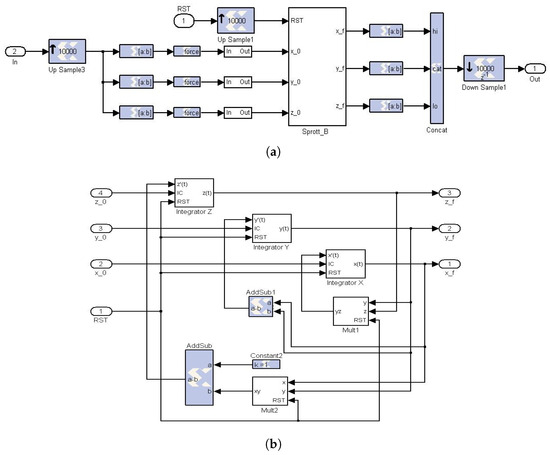
Figure 2.
Schematic circuit view of the CB-SBox model and its Sprott B subsystem, available in [59]. (a) Chaos-Based Substitution Box (CB-SBox). (b) Sprott B [5] subsystem of Equation (7).
The parameters used to configure the circuit presented in Figure 2 are fully programmable and allow for the realization of the Sprott B-based CB-SBox in different lengths, i.e., the number of bits (NOB). Several precomputed parameters are stored in two configuration datasets, named PRM (Parallelepiped Relations Measurements) and Slice, which are available online in [59]. Each selected length (i.e., NOB) is associated with its own pair of datasets (PRM and Slice), built such that any CB-SBox input generates an initial condition (, , ) belonging to (see Figure 1). The values from the PRM and Slice datasets are used to configure the internal components of the programmable CB-SBox model (available in [59]), which are then implemented in the circuit shown in Figure 2.
Each PRM dataset synthesizes, for a given NOB value, the dimensions of non-overlapping parallelepipeds within (see Figure 1) as exemplified in Table 2. Additionally, the PRM dataset lists, based on the selected dimensions and the applied Discretization Criterion (DC), the bit lengths before and after the binary point for the limiting vertices of the () parallelepipeds, including their respective axial distances ().
Table 2.
The dimensions of three non-overlapping parallelepipeds belonging to the volume of valid initial conditions () shown in Figure 1.
The Slice dataset is specified by the NOB parameter and the values stored in the corresponding PRM dataset. The parameters contained in the Slice dataset are used to configure the force and slice blocks of the model shown in Figure 2b. The circuit depicted in Figure 2 operates under the control of a reset signal, whose period is defined by the internal parameter LongRun. This reset signal initializes the CB-SBox to a new initial condition at the beginning of each LongRun cycle. It also controls the three integrators by triggering two dynamic registers within each one, both of which feature a configurable initial condition port. Additionally, the reset signal forces the two multipliers in Figure 2b to a null initial state at the start of each cycle. The integrators are further governed by an integration step size parameter (), set to , and the multipliers operate with a latency parameter () of 5.
4. CB-SBox Performance Analysis
The main distinction between the block cipher presented in Section 5 and that introduced in [30] lies in the implementation of the S-boxes. In the design proposed here, they are realized using the Chaos-Based Substitution Box (CB-SBox) model described in Section 3 (see Figure 2). In contrast, the S-boxes in [30] are implemented as ROM blocks populated through an offline procedure that precomputes the outputs of a chaotic map.
For fair comparison purposes, both designs—the CB-SBox from Section 3 and a ROM-based version implemented by the authors based on the method described in Jakimoski [30]—were synthesized in ASIC using VHDL. The synthesis tool employed was DC Synopsys, version Z-2007.03-SP4, for Linux, using the UMC CMOS 0.13 m technology library. This setup ensures a more balanced comparison than FPGA-based implementations with VHDL code automatically generated by the system generator since specific architectural features in most FPGAs—such as embedded multipliers and memory blocks—can disproportionately impact resource usage, particularly the number of slices consumed.
4.1. Area and Power Analysis
A comparison is presented between area (m2) and power consumption (W), both plotted along the x-axis, and circuit size, plotted along the y-axis. These comparisons are illustrated in Figure 3 and Figure 4, respectively, for the ROM-based and CB-SBox implementations. The size is defined by the number of bits (NOB) of the circuit input, which equals the output size due to design symmetry.
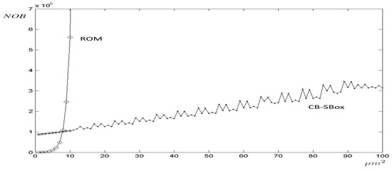
Figure 3.
Area comparison between ROM-Based and CB-SBox implementations as a function of circuit input size (NOB).
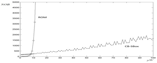
Figure 4.
Power consumption comparison between ROM-Based and CB-SBox implementations as a function of circuit input size (NOB).
As shown in Figure 3 and Figure 4, both the area and power consumption of the ROM-based S-boxes increase exponentially with NOB. For a ROM implementation with NOB , meaning both input and output signals are 8 bits wide (corresponding to a memory depth of 256 positions), the area reaches m2 and the power consumption is W. When increasing the word length by one bit (NOB ), both area and power consumption nearly double, reaching m2 and W, respectively. Note that the ROM block was implemented up to NOB = 13; larger configurations could not be synthesized due to software and hardware limitations and had to be extrapolated.
In the case of the proposed CB-SBox, as shown in Figure 3 and Figure 4, there is no strong exponential growth as observed in the ROM case. In fact, the CB-SBox consists of components (multipliers, adders, subtractors, multiplexers, and registers), whose area and power consumption exhibit a nearly linear dependence on the circuit size (NOB). The only CB-SBox components with a non-linear dependence on NOB are the multipliers, but they do not significantly affect the overall area and power consumption of the circuit. Consequently, the area and power consumption of the CB-SBox increase almost linearly with NOB.
The area and power consumption of both ROM and CB-SBox designs are plotted together in Figure 3 and Figure 4, respectively. In these figures, the strong exponential behavior of the ROM implementation is evident, in contrast to the nearly linear behavior of the CB-SBox implementation. It can also be observed that the equilibrium point occurs near NOB , leading to the conclusion that for circuits requiring a word length greater than 8 bits, the CB-SBox design outperforms the ROM-based implementation in terms of area and power consumption.
4.2. Timing Analysis
Section 4.1 demonstrates that the area and power consumption of an S-box based on the CB-SBox implementation are superior to those of the ROM-based design for S-boxes with NOB . However, it is important to note that the latency of the CB-SBox implementation (defined by the LongRun parameter) is significantly higher compared to that of the ROM implementation. In chaos-based circuits, a substantially larger number of iterations is required to produce an output that is statistically uncorrelated with its input, whereas the ROM block delivers a precomputed value in a single clock cycle.
The LongRun parameter is determined by the selected Discretization Criterion (DC) [51]: the higher the DC, the larger the LongRun value required to decorrelate the CB-SBox input from its output. Based on the DC values stored in the PRM (Parallelepiped Relations Measurements) configuration dataset, Figure 5 shows the LongRun parameter (y-axis) as a function of the input size (NOB) of the CB-SBox circuit.
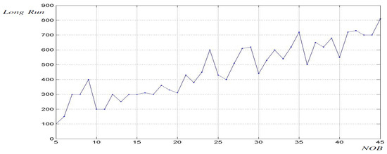
Figure 5.
Time response of the CB-SBox: LongRun parameter versus circuit size (measured in NOB).
As shown in Figure 5, the relationship between the LongRun parameter and the NOB used in the CB-SBox exhibits an increasing trend. The data presented in Figure 5 were obtained through simulations of groups of 500 initial conditions (ICs). Each group of ICs was created using a specific Discretization Criterion (). The DC parameter is inversely proportional to the minimum distance between any pair of ICs within the group. The LongRun parameter represents the time required for each group of 500 ICs to fully disperse across the volume of the strange attractor [51].
The location of each group of 500 ICs is a uniformly distributed random variable constrained within the volume of valid initial conditions () [50]. Distinct groups, depending on their position within , exhibit different dispersion patterns. This behavior can be observed even in groups generated with the same DC, which results in the irregular behavior characterized by significant fluctuations as shown in Figure 5. This phenomenon
is further analyzed below at the end of Section 4.2, in the penultimate paragraph.
For illustration purposes, a three-dimensional cube of 729 ICs is plotted in Figure 6 in green. Its location is randomly placed within , , and . The Discretization Criterion (DC) is set to 4, so the distance between successive ICs is 0.0625, making it easy to identify the green cube in Figure 6. These 729 ICs were simulated using Equation (7), and their corresponding final states are plotted in blue. It can be observed that the final states tend toward the Sprott B Strange Attractor (shown in yellow) as expected, and their locations disperse on the attractor due to the butterfly effect. Figure 6 shows the three-dimensional dispersion pattern for 7 and 100 iteration steps. The project database, available online in [59], includes 27 additional three-dimensional dispersion patterns up to 1900 iteration steps, in both JPG and FIG formats.
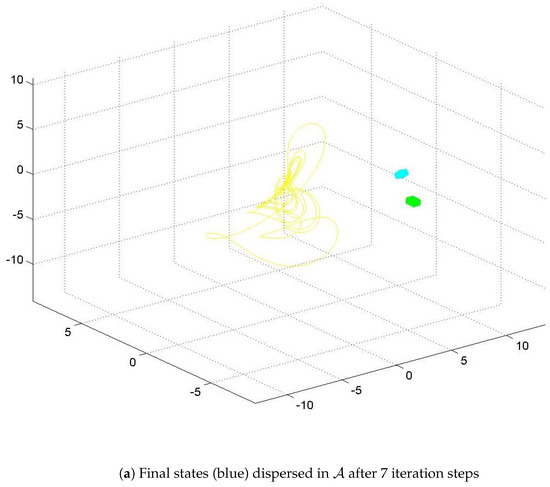
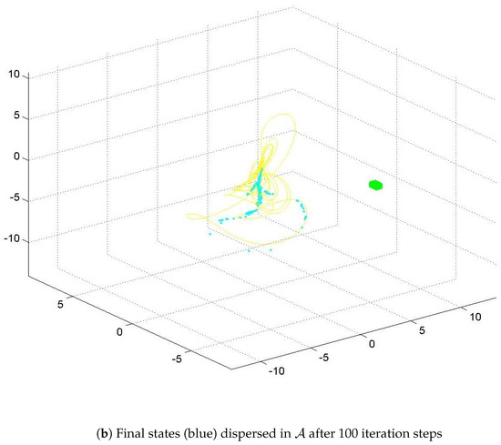
Figure 6.
Visualization of a cube with 729 initial conditions (in green) and the three-dimensional dispersion of their corresponding final states (in blue) over the Sprott B attractor (in yellow). An additional 27 visualization steps are available online in the project dataset [59].
Despite extensive efforts (1300 groups of 500 ICs were simulated, each group constructed with DC ), no discernible pattern was identified linking the spatial locations of the IC groups within to the LongRun parameter. Figure 7 illustrates the variation of the LongRun parameter with respect to the spatial distribution of the IC groups within . This figure presents a representative subset of 79 IC groups. The center of each group is defined by its x- and y-axis coordinates at a fixed elevation of . The LongRun parameter is encoded using the following seven-symbol scheme (not all symbols appear in the subset shown in Figure 7): a blue point • indicates that the required LongRun parameter lies within the interval ; a green circle ∘ corresponds to LongRun ; a red square ■ to LongRun ; a cyan multiplication sign × to LongRun ; a magenta addition sign + to LongRun ; a yellow lozenge ✧ to LongRun ; and a black asterisk * to LongRun . The lack of a clear spatial correlation between group locations and the LongRun parameter suggests the influence of other contributing factors, potentially arising from the system’s inherent chaotic dynamics, which warrant further investigation.
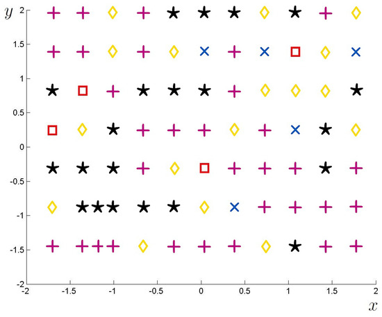
Figure 7.
Spatial distribution of the LongRun parameter (within the graph) for 79 groups of 500 ICs located in the plane , with , and the following markers: ■ LongRun ∈, × LongRun ∈, + LongRun ∈, ✧ LongRun ∈, and * LongRun ∈.
The timing analysis presented in this Section 4.2 is intrinsically linked to the circuit throughput. For a ROM-based S-box, its contents are precomputed prior to runtime, and during operation, the output becomes available with minimal latency. In contrast, the CB-SBox proposed in this work generates outputs dynamically, which requires additional computation time during operation. This latency is governed by the LongRun parameter, which increases as the value decreases as previously discussed. Consequently, this behavior directly impacts the circuit throughput as will be further analyzed in Section 5, where the proposed CB-SBox is applied to a practical implementation of a Feistel block cipher based on [30].
4.3. Security Analysis
Linear cryptanalysis [60] and differential cryptanalysis [61] are the two most prominent attacks applicable to cryptographic schemes [56]. These attacks rely on identifying structural weaknesses in the non-linear components responsible for confusion: the S-boxes (the proposed CB-SBox in this work). The initial step in both techniques involves computing two quantitative parameters dependent on the properties of the S-boxes: the Linear Probability Bias and the Differential Probability Bias.
The effort required to compute the two parameters (Linear and Differential Probability Biases) increases exponentially with the NOB of the S-box, as illustrated in Figure 8, which presents the computation time (in seconds) for each parameter calculation. The values for NOB were obtained through actual computations, while those for NOB were extrapolated based on the exponential trend observed for the lower NOB values. The time required to compute the Linear and Differential Probability Biases represents the initial step in the cryptanalysis of a block cipher and does not directly indicate its resistance to these attacks. Rather, the cipher’s vulnerability is determined by the magnitude of the resulting biases—lower bias values correspond to higher resistance to linear and differential cryptanalysis. Nevertheless, performing this computation is a necessary preliminary step in evaluating and strengthening cipher security. As shown in Figure 8a, computing the Linear Probability Bias for NOB required 10 days, and it is estimated that for NOB , the process would take approximately 2 years. The proposed CB-SBox supports larger NOB values than conventional ROM-based S-boxes, providing a strong initial barrier against cryptanalytic attacks.
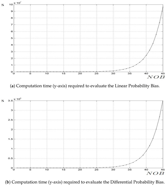
Figure 8.
Security analysis based on the computation time (seconds) required to evaluate the Linear and Differential Probability Biases of S-boxes as a function of their size (NOB).
4.4. Bijectivity Analysis
The proposed Chaos-Based Substitution Box (CB-SBox) maps all possible inputs within (as shown in Figure 1) to their corresponding outputs by iterating the chaotic map defined in Equation (7) over a sufficiently long period (LongRun). This process enables the outputs to spread across the strange attractor due to the butterfly effect as illustrated in Figure 6. As a result of the inherent nature of chaotic systems—characterized by sensitive dependence on initial conditions and the fractal structure of strange attractors—iterating Equation (7) for an extended duration causes the outputs to become not only widely dispersed across the attractor but also potentially mapped to locations already assigned to other outputs, leading to an inherently non-bijective behavior.
CB-SBoxes with different numbers of bits (NOB) were simulated, and the results are summarized in Table 3. Their deterministic outputs were stored in matrices referred to as SBOX Chaotic, each of length as specified in Table 3. Additional matrices of identical dimensions, named SBOX Chaotic Counter, were employed to record the number of times each output value occurred during the simulations. For a matrix to be considered bijective, each output must appear exactly once, which corresponds to a bijectivity index of 100%, meaning that the number of ones (1s) in the SBOX Bijective Counter matrix is 100%.
Table 3.
Statistical analysis of the bijectivity of CB-SBoxes, where NOB denotes the number of bits, followed by the corresponding table length that equals and the calculated bijectivity index (data available online in [59]).
Due to their chaotic nature, the proposed CB-SBoxes are inherently non-bijective, exhibiting a mean bijectivity index of 63.57% across the simulated cases presented in Table 3. This indicates that only this proportion of possible outputs was mapped by the CB-SBox during the simulations, while the remaining 36.43% of outputs were never mapped, corresponding to the proportion of zeros (0s) in the SBOX Chaotic Counter. The complete statistical dataset referenced in this analysis is available online in [59].
The lack of bijectivity is a factor that must be considered from a holistic perspective as discussed in more detail in Section 4.5. S-boxes are integral components of various cryptographic schemes, primarily introducing non-linearity and confusion to enhance security. Traditionally, S-boxes are bijective, which is crucial for invertibility in these cryptographic processes. However, certain cryptographic schemes, such as hash functions, stream ciphers, specific cryptographic protocols, and Feistel networks, can employ non-bijective S-boxes, where the lack of bijectivity does not compromise security or functionality as demonstrated in other scientific works [44,45].
4.5. Joint Analysis
As discussed in Section 4.1, when dealing with large S-boxes (NOB ), it is more advantageous to implement a CB-SBox rather than using a ROM-based approach due to the exponential growth of the latter, resulting in significantly smaller circuits with lower power consumption when using the CB-SBox.
However, as pointed out in Section 4.2, this approach results in slow response times: due to the Butterfly Effect [57], chaotic behavior takes a long time to fully develop as shown in Figure 5 and Figure 6.
The analysis presented in Section 4.3 shows that, despite its slow response time, the CB-SBox is a valuable approach for enhancing the security of block ciphers: the CB-SBox enables the implementation of large S-boxes, which enhances the cipher’s resistance to linear and differential cryptanalysis as shown in Figure 8.
The bijectivity of the proposed CB-SBox is analyzed in Section 4.4. The CB-SBox exhibits a mean bijectivity index of 63.57%, indicating non-bijective behavior resulting from the chaotic nature of the Sprott B [5] map used within. Several scientific works have addressed this issue by the offline substitution of repeated S-box outputs. However, this approach was not adopted in the present research, as it would undermine the primary advantage sought in this work: the emulation of a large S-box functioning during execution.
It is worth noting that the CB-SBox design not only facilitates the implementation of large S-boxes (NOB ) but also achieves this with smaller circuits (lower area) and reduced power consumption, compared to a ROM-based implementation. A realizable 30-bit CB-SBox, with a security level equivalent to that of a 30-bit non-realizable (within the scope of this work) ROM implementation, both requiring 17 days for the Linear Probability Bias calculation, consumes only 0.0004% of the area and power needed by the 30-bit ROM.
Therefore, the joint analysis presented here in Section 4.5 demonstrates that the CB-SBox offers an effective solution when a high level of security is required. The latency issue addressed in Section 4.2 can be mitigated by the compact area and low-power-consumption characteristics of the CB-SBox, with a parallel circuit implementation serving as an alternative to attenuate the high-latency problem discussed in Section 4.2. Further details regarding this are provided in Section 5, which focuses on the Feistel network implementation using the proposed CB-SBox.
5. CB-SBox in a Feistel Network
The Chaos-Based Substitution Box (CB-SBox) developed in this work was employed in the construction of a Feistel network based on the architecture proposed by Jakimoski [30]. In the present study, the precomputed ROM-based S-boxes utilized in [30] were substituted by the proposed CB-SBox, which is detailed in Section 3 and analyzed in Section 4.
The schematic diagram of the designed block cipher is shown in Figure 9, which implements Equation (9), obtained from Jakimoski’s work [30]. Figure 9a illustrates the complete block cipher with its three inputs: the plaintext divided into words, where ; the round-related subkeys , where ; and the reset signal. Figure 9a also shows its output, which is the ciphertext , obtained after r rounds:
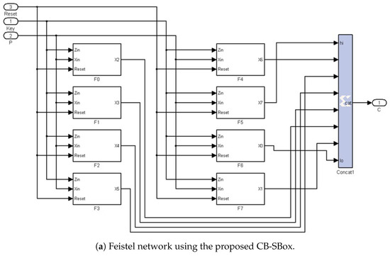
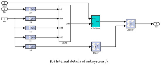
Figure 9.
Schematic diagram of the encryption block cipher, where the CB-SBox, embedded within each subsystem and previously detailed in Figure 2, is highlighted in blue.
Figure 9b illustrates the internal details of subsystem in Figure 9a, where the CB-SBox subsystem is highlighted in blue (its schematic diagram is presented in Figure 2). All subsystems to in Figure 9a exhibit a similar structure to the one shown in Figure 9b, each containing one CB-SBox but with an XOR port having different inputs as described by Equation (9).
As discussed in Section 3, the CB-SBox is a programmable circuit whose word length ( NOB ) can be configured through PRM and Slice datsets available online in [59]. Consequently, since the block cipher illustrated in Figure 9 comprises eight CB-SBoxes, the total word length processed by the cipher can be programmed to range from 88 to 328 bits. In the example shown in Figure 9, the cipher is implemented with a total word length of 136 bits.
The block cipher is implemented recursively: only a single round of the cipher is physically realized, and the intermediate encrypted words , where , are fed back to the input times to complete the required r rounds of encryption.
The decryption architecture is derived from Equation (10), as presented in [30], by applying the inverse transformations defined in Equation (9): the round subkeys are applied in reverse order, and the same number of rounds r are performed on the ciphertext block to recover the original plaintext block . The decryption operation involves series connections between the blocks, requiring eight times as many clock cycles to complete its tasks compared to encryption, due to the feedback arrangement shown in Figure 10:
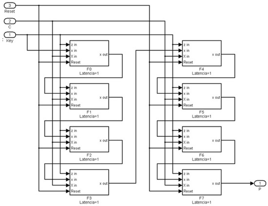
Figure 10.
Schematic representation of the decryption block cipher.
The block cipher implementation results in a multi-rate circuit as a result of the presence of up and down samplers in the architecture shown in Figure 2, which are integrated within the CB-SBox subsystem depicted in Figure 9. These samplers are necessary to compensate for the latency introduced by the multipliers, which equals five clock cycles, and the integration step size, set to 0.01. These parameters are used in the implementation of the Sprott B differential chaotic map defined in Equation (7). The block cipher operation is controlled by a reset signal, which synchronizes the loading of initial conditions with the cycle initialization, governed by the LongRun parameter.
The performance analysis of the FPGA-implemented block cipher is presented in Figure 11. This figure includes four graphs, each plotted as a function of the NOB (x-axis): the size of the proposed programmable CB-SBox. Figure 11a shows the maximum operating frequency of the circuit, measured in MHz (y-axis). As the size of the CB-SBox increases, the maximum frequency decreases as expected. Based on Figure 11a, the interval NOB was selected as the target design range.
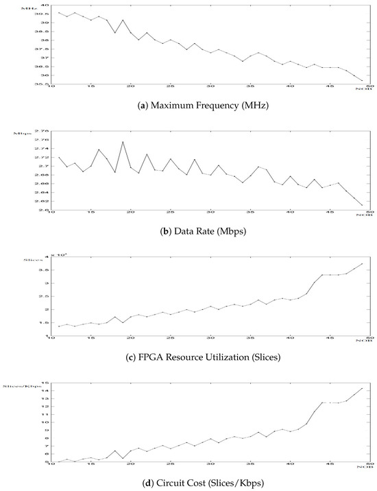
Figure 11.
FPGA performance of the block cipher.
Figure 11b illustrates the data rate, measured in Mbps (y-axis), computed as the product of the maximum circuit frequency and the size of the encrypted word, while accounting for the compensation required by the LongRun parameter. As discussed in Section 4.2, the timing analysis of the CB-SBox is intrinsically linked to the circuit throughput. In ROM-based S-box architectures, the output is available with minimal latency. In contrast, the CB-SBox proposed in this work incurs additional computational delay during execution. As a result, this behavior directly impacts the overall throughput of the cipher. Figure 11b reveals a peak data rate of 2.755 Mbps at NOB , which is significantly lower than the typical 10 Mbps achieved by ROM-based implementations.
The remaining two graphs present the hardware resource utilization, measured in FPGA slices as shown in Figure 11c, and the circuit cost, measured in slices per Kbps as presented in Figure 11d. Both graphs exhibit a local minimum at NOB , justifying the selection of this value as the optimal operating point for the proposed CB-SBox architecture.
The chosen operating point (NOB ) lies in the region where the CB-SBox exhibits superior performance in terms of area and power consumption when compared to ROM-based S-box implementations as illustrated in Figure 3 and Figure 4. These figures show that a 19-bit CB-SBox implementation utilizes only 0.0238% of the area and 0.0241% of the power consumed by a securely equivalent, but physically unrealizable, ROM-based counterpart. It is important to highlight that the proposed CB-SBox constitutes the only deviation from the block cipher structure described in [30]. Moreover, it should be emphasized that NOB corresponds to the largest realizable ROM implementation feasible with the hardware and software resources available in the laboratory.
As discussed in Section 4.5, the main advantage of applying the CB-SBox to the Jakimoski-based cipher [30] is the ability to implement large S-boxes (NOB ), thereby achieving high levels of resistance against linear and differential cryptanalysis. The block cipher designed in this work, which employs a 19-bit CB-SBox, requires approximately 20 h to compute the Linear Probability Bias and 38 min to compute the Differential Probability Bias as shown in Figure 8. Such a 19-bit implementation would not be feasible using a ROM-based approach. It is also important to emphasize that this analysis represents only the initial step in the process of attacking a cipher through linear and differential cryptanalysis.
The described 152-bit recursive block cipher, employing the proposed CB-SBox and configured with four rounds, was applied to the ’Lena’ image as illustrated in Figure 12a. The image was converted into a matrix, with each pixel represented using 8 bits. To align with the cipher’s 152-bit block size, bit-padding with 18 one bits was applied. The padded data were then encrypted, and the resulting cipher image is presented in Figure 12b. After decryption, the 18 padding bits were removed from the last block, thereby restoring the original matrix. The decrypted image is shown in Figure 12c. The FPGA-implemented block cipher required 6.09 s for encryption and 51.76 s for decryption.
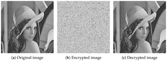
Figure 12.
Results of applying the 152-bit recursive block cipher to the ‘Lena’ image.
Besides image encryption, the 152-bit block cipher described in this section, employing the proposed CB-SBox, was also applied to text encryption. The abstract of this work, shown in the upper part of Figure 13, was converted into a 1691-bit character string, padded with 14 one bits, and used as the plaintext. The corresponding ciphertext is shown in the lower part of Figure 13. Since the plaintext is based on a LaTeX text fragment, it consists solely of basic ASCII characters, corresponding to codes ranging from 0 to 127, even after one-bit padding, and is represented using 8-bit encoding, which accommodates values from 0 to 255. In contrast, the ciphertext utilizes the full 8-bit ASCII range and, therefore, includes special characters with codes between 128 and 255. As some special characters cannot be properly represented graphically, a hexadecimal representation is employed as illustrated in the lower part of Figure 13. This behavior is further observed in Figure 14, which presents the plaintext histogram (Figure 14a) ranging from 0 to 127, the flattened ciphertext histogram (Figure 14b) ranging from 0 to 255, and the deciphered text histogram (Figure 14c) ranging from 0 to 127 but exhibiting a small peak in the left due to the one-bit padding, which does not appear in the plaintext histogram (Figure 14a) as expected.
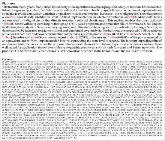
Figure 13.
Original and encrypted versions of the LaTeX text presenting the abstract of this work, encrypted using the 152-bit recursive block cipher based on the proposed CB-SBox. The corresponding dataset is available online [59].
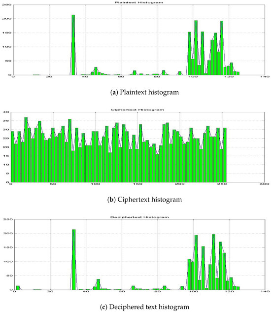
Figure 14.
Histograms after applying the 152-bit encryption process, which employs the proposed CB-SBox, to the abstract of this paper, written in LaTeX. The corresponding dataset is available online [59].
The following hardware and software resources were used in the present research: a ThinkPad E14 Gen2 computer manufactured by Lenovo in Brazil, with an 11th Generation Intel® Core™ i5-1135G7 @ 2.40 GHz processor (base frequency 2.42 GHz), featuring 4 physical cores and 8 logical processors, 8 GB of RAM, and 128 MB of video memory, running Windows 11 Pro 64-bit, version 22H2. A virtual machine was also used with the following specifications: Oracle VM VirtualBox 7.0 (version 7.0.18 r162988), with 2 GB of RAM allocated from the 8 GB available on the host system, 32 MB of video memory allocated from the 128 MB available, and 2 CPU cores allocated from the 8 logical cores available. The virtual machine runs the following software: Windows XP (32-bit), v5.1, build 2600, Service Pack 1 as the operating system; MATLAB version 6.5.0.180913a (Release 13); Xilinx ISE Design Suite v12, P/N 1050504-01, Xilinx Project Navigator v6.2i; Xilinx System Generator Blockset version v6.1(c); and ModelSim XE 6.2i. A Xilinx Spartan-3 development board manufactured by Avnet in USA, P/N ADS-XLX-SP3-DEV2000, was also used featuring the following main components: Xilinx XC3S1500/2000-FG676 Spartan-3 FPGA, 43 MB Micron DDR SDRAM, 16 MB Flash, 2 MB SRAM, a 2×16 LCD, a 128×64 OSRAM OLED display, and an audio codec.
6. Conclusions
This research presents a new approach for the design of block ciphers. It is based on the fixed-point realization of a non-linear differential equation exhibiting chaotic behavior. This realization, called Chaos-Based Substitution Box (CB-SBox), enables the implementation of large S-boxes. Such entities bring significant advantages in terms of area and power consumption when compared to a typical ROM-based s-box: a 19-bit long CB-SBox requires only 0.0238% of the area and 0.0241% of the power used by an equivalent but non-feasible ROM-based implementation. They also achieve a high level of security, measured by the time necessary to compute the first step of linear and differential cryptanalysis, a task that cannot be achieved by their ROM-based counterparts.
As a consequence of the butterfly effect, this approach has the disadvantage of a long iteration time (governed by the LongRun parameter) required to uncorrelate the CB-SBox input signals (the chaotic map’s initial condition) from its output (the chaotic map’s final states).
The CB-SBox was used as the source of confusion in a block cipher based on the architecture proposed by Jakimoski [30]. This cipher was implemented using a programmable circuit where the CB-SBox can be realized with different sizes, according to the parameters stored in the PRM and Slice datasets (available online in [59]). This enables a block cipher with a programmable key size. We analyzed the performance of the block cipher as a function of the size (NOB) of its CB-SBox, deciding to operate at NOB as a solution to globally maximize the circuit data rate while keeping the circuit size low and achieving high levels of security.
To conclude this work, six open research areas have been identified and are discussed below. When a given group of initial conditions (ICs), belonging to the volume of valid initial conditions (), is stimulated by a chaotic map, it disperses into the volume of the strange attractor due to the butterfly effect. The temporal evolution pattern of the intermediate states may lead to the misleading conclusion that, depending on the relative position of this group of initial conditions, more time would be required for it to fully disperse throughout the attractor. The results presented in Figure 7 suggest an inconclusive relationship, making the correlation between the position of a group of ICs versus dispersion time a promising topic for future investigation.
Another potential research direction involves the implementation of a programmable Chaos-Based Substitution Box, in which not only the S-box length (NOB) can be configured—as demonstrated in the present CB-SBox—but also the chaotic map itself can be dynamically altered. This capability would enhance the adaptability and security level of the target encryption primitive.
In this study, the Sprott B chaotic map [5] was selected among six other candidates, based on the criteria provided in [51]. The computation of chaotic properties such as is highly time-consuming but is worthwhile since it not only allows for a better use of the chaos map in the encryption process but also directly addresses quantization errors and dynamical degradation. A valuable extension of the present work would be to replicate the methodology of [51] using other chaotic systems, including hyperchaotic maps, higher-dimensional systems, systems exhibiting multiple attractors, and those with greater ergodicity as found in the literature [29,37,39,62,63]. It is expected that a chaotic map with improved ergodicity could reduce the LongRun parameter, thus increasing encryption throughput, and can also flatten the histogram plot of Figure 14b, combating a potential weakness of the proposed C-SBox: its capability to better spread the final states over all state space.
Non-bijective S-boxes, like the proposed CB-SBox, are suitable only for specific types of cryptographic primitives, such as the Feistel network implemented in this work. An additional future direction includes the usage of the CB-SBox concepts in the design and evaluation of hash functions—non-invertible primitives—along with their implementation in ASICs.
This research also examined the CB-SBox’s resistance to linear and differential cryptanalysis, demonstrating that large S-box sizes contribute positively to security. Further work could involve exploring alternative attack vectors found in the literature, as well as proposing novel attack strategies tailored to the developed CB-SBox architecture.
In the present work, the primary focus is the comparison between the proposed chaos-based S-box (CB-SBox) and a ROM-based implementation. Other approaches to implementing S-boxes, such as logic gate designs, are also available. Although such implementations typically focus on small S-boxes, there is no fundamental impediment to implementing larger ones and comparing them with the CB-SBox, which is suggested as future work.
Author Contributions
Conceptualization, É.C.D.e.S.J., C.A.d.M.C., L.S.I., W.A.F. and M.G.; data curation, É.C.D.e.S.J. and I.A.L.S.; formal analysis, É.C.D.e.S.J., C.A.d.M.C. and W.A.F.; funding acquisition, É.C.D.e.S.J., L.S.I. and M.G.; investigation, É.C.D.e.S.J.; methodology, É.C.D.e.S.J., W.A.F. and C.A.d.M.C.; project administration, É.C.D.e.S.J., C.R.P.d.S.J. and C.A.d.M.C.; resources, É.C.D.e.S.J., F.G.S., C.R.P.d.S.J., L.S.I. and I.A.L.S.; software, É.C.D.e.S.J., F.G.S., L.S.I. and I.A.L.S.; supervision, C.A.d.M.C.; validation, É.C.D.e.S.J. and C.A.d.M.C.; visualization, É.C.D.e.S.J.; writing—original draft preparation, É.C.D.e.S.J.; writing—review and editing, É.C.D.e.S.J. and C.A.d.M.C.; All authors have read and agreed to the published version of the manuscript.
Funding
This research was supported by the SENAI Institute of Innovation in Microelectronics (ISI-ME) and the National Service for Industrial Apprenticeship (SENAI), which covered the article processing charges (APC) and other associated research costs. Partial funding was also provided by the Commission for Coordination and Implementation of the Amazon Surveillance System (SIVAM), which supported travel expenses, and by the Microelectronic Systems (MES) Research Group at Technische Universität Darmstadt, which provided software and hardware resources.
Data Availability Statement
The original data presented in the study are openly available in Zenodo research repository at https://zenodo.org/records/14967851, (accessed on 7 May 2025) [59].
Acknowledgments
The authors would like to thank the following institutions and their prominent members for supporting this research in a broad and collaborative context: the Federation of Industries of the State of Amazonas (FIEAM); the SENAI Institute of Innovation in Microelectronics (ISI-ME), the Superintendency of Innovation and Technology (SITEC), the National Directorate (DN) and Amazonas Regional Directorate (DR-AM) of SENAI – the National Service for Industrial Training; the Center for R&D in Electronic and Information Technology (CETELI) and the Graduate Program in Electrical Engineering (PPGEE) at the Federal University of Amazonas (UFAM); the Coordination for the Improvement of Higher Education Personnel (CAPES), the National Council for Scientific and Technological Development (CNPq), and the Amazonas State Research Support Foundation (FAPEAM), Brazilian funding agencies for science, technology, and academic development; the Brazilian Society of Microelectronics (SBMicro); the Microelectronic Systems (MES) Research Group at Technische Universität Darmstadt (TUD); Rohde & Schwarz; the University of Leeds (UoL); the Center for Telecommunication Studies (CETUC) at the Pontifical Catholic University of Rio de Janeiro (PUC-Rio); the Commission for the Coordination and Implementation of the Amazon Surveillance System (SIVAM); the Aeronautics Institute of Technology (ITA); and the Institute for Advanced Studies (IEAv).
Conflicts of Interest
The authors declare no conflicts of interest.
Abbreviations
The following abbreviations are used in this manuscript:
| ASIC | Application-Specific Integrated Circuit |
| CB-SBox | Chaos-Based Substitution Box |
| DC | Discretization Criterion |
| DTR | Distance-to-Time Ratio |
| FPGA | Field-Programmable Gate Array |
| IC/ICs | Initial Condition/Initial Conditions |
| LUT | Look-Up Table |
| LongRun | Execution time required for the outputs to fully disperse over |
| Mbps | Megabits per second |
| MBps | Megabytes per second |
| MDT | Maximum Dispersion Time |
| NOB | Number of Bits |
| PRM | Parallelepiped Relations Measurements (used as a configuration dataset) |
| ROM | Reed Only Memory |
| S-Box | Substitution Box |
| Slice | Parameters for segmentation and selection (used as a configuration dataset) |
| SIVAM | Amazon Surveillance System |
| VHDL | VHSIC Hardware Description Language |
| VHSIC | Very High Speed Integrated Circuit |
| Strange Attractor | |
| All Attractors | |
| Convergent Attractors | |
| Divergent Attractors | |
| Mean function | |
| Bounding Parallelepiped | |
| Temporal derivative function | |
| Attractor Density | |
| Depth dimension of the largest parallelepiped within | |
| Distance Small | |
| Function that relates to the time to spread beyond the threshold | |
| Height dimension of the largest parallelepiped within | |
| latency parameter | |
| Maximum function | |
| Minimum function | |
| Smaller Parallelepiped | |
| Set of s belonging to a state space | |
| step size integration parameter | |
| Variation function | |
| Volumetric Histogram | |
| Volume valid of Initial Conditions | |
| Volume function | |
| Largest Subset Volume | |
| Width dimension of the largest parallelepiped within | |
| Cardinality function of sets | |
| Complement operation of sets | |
| ∪ | Union operator of sets |
References
- Lorenz, N.E. Deterministic non-periodic flows. J. Atmos. Sci. 1963, 20, 130–141. [Google Scholar] [CrossRef]
- Rössler, O.E. An equation for continuous chaos. Phys. Lett. A 1976, 57, 397–398. [Google Scholar] [CrossRef]
- May, R. Simple mathematical models with very complicated dynamics. Nature 1976, 261, 459–467. [Google Scholar] [CrossRef]
- Sprott, J.; Linz, S. Algebraically simple chaotic flows. Int. J. Chaos Theory Appl. 2000, 5, 1–20. [Google Scholar]
- Sprott, J. Some simple chaotic flows. Phys. Rev. E 1994, 50, R647–R650. [Google Scholar] [CrossRef] [PubMed]
- Chua, L. The Genesis of Chua’s Circuit; Electronics Research Laboratory, College of Engineering, University of California: Los Angeles, CA, USA, 1992. [Google Scholar]
- Linz, S.; Sprott, J. Elementary chaotic flow. Phys. Lett. A 1999, 259, 240–245. [Google Scholar] [CrossRef]
- Li, S.; Zheng, X.; Mou, X.; Cai, Y. Chaotic encryption scheme for real-time digital video. In Real-Time Imaging VI, Proceedings of SPIE; Citeseer: Princeton, NJ, USA, 2002; Volume 4666, pp. 149–160. [Google Scholar]
- Tenny, R.; Tsimring, L. Additive mixing modulation for public key encryption based on distributed dynamics. IEEE Trans. Circuits Syst. I Regul. Pap. 2005, 52, 672–679. [Google Scholar] [CrossRef]
- Bose, R.; Pathak, S. A novel compression and encryption scheme using variable model arithmetic coding and coupled chaotic system. IEEE Trans. Circuits Syst. I Regul. Pap. 2006, 53, 848–857. [Google Scholar] [CrossRef]
- Zou, C.; Zhang, Q.; Wei, X.; Liu, C. Image Encryption Based on Improved Lorenz System. IEEE Access 2020, 8, 75728–75740. [Google Scholar] [CrossRef]
- Khan, M.F.; Ahmed, A.; Saleem, K.; Shah, T. A Novel Design of Cryptographic SP-Network Based on Gold Sequences and Chaotic Logistic Tent System. IEEE Access 2019, 7, 84980–84991. [Google Scholar] [CrossRef]
- Feng, W.; Zhang, J.; Qin, Z. A Secure and Efficient Image Transmission Scheme Based on Two Chaotic Maps. Complexity 2021, 2021, 1898998. [Google Scholar] [CrossRef]
- Feng, W.; Wang, Q.; Liu, H.; Ren, Y.; Zhang, J.; Zhang, S.; Qian, K.; Wen, H. Exploiting Newly Designed Fractional-Order 3D Lorenz Chaotic System and 2D Discrete Polynomial Hyper-Chaotic Map for High-Performance Multi-Image Encryption. Fractal Fract. 2023, 7, 887. [Google Scholar] [CrossRef]
- Feng, W.; Zhang, J.; Chen, Y.; Qin, Z.; Zhang, Y.; Ahmad, M.; Woźniak, M. Exploiting robust quadratic polynomial hyperchaotic map and pixel fusion strategy for efficient image encryption. Expert Syst. Appl. 2024, 246, 123190. [Google Scholar] [CrossRef]
- Feng, W.; Yang, J.; Zhao, X.; Qin, Z.; Zhang, J.; Zhu, Z.; Wen, H.; Qian, K. A Novel Multi-Channel Image Encryption Algorithm Leveraging Pixel Reorganization and Hyperchaotic Maps. Mathematics 2024, 12, 3917. [Google Scholar] [CrossRef]
- Ma, X.; Wang, Z.; Wang, C. An Image Encryption Algorithm Based on Tabu Search and Hyperchaos. Int. J. Bifurc. Chaos 2024, 34, 2450170. [Google Scholar] [CrossRef]
- Qian, K.; Xiao, Y.; Wei, Y.; Liu, D.; Wang, Q.; Feng, W. A Robust Memristor-Enhanced Polynomial Hyper-Chaotic Map and Its Multi-Channel Image Encryption Application. Micromachines 2023, 14, 2090. [Google Scholar] [CrossRef]
- Yu, F.; Zhang, S.; Su, D.; Wu, Y.; Gracia, Y.M.; Yin, H. Dynamic Analysis and Implementation of FPGA for a New 4D Fractional-Order Memristive Hopfield Neural Network. Fractal Fract. 2025, 9, 115. [Google Scholar] [CrossRef]
- Baptista, M. Cryptography with chaos. Phys. Lett. A 1998, 240, 50–54. [Google Scholar] [CrossRef]
- Wong, K.; Yuen, C. Embedding compression in chaos-based cryptography. IEEE Trans. Circuits Syst. II Express Briefs 2008, 55, 1193–1197. [Google Scholar] [CrossRef]
- Chen, J.; Zhou, J.; Wong, K. A Modified Chaos-Based Joint Compression and Encryption Scheme. IEEE Trans. Circuits Syst. II Express Briefs 2011, 58, 110–114. [Google Scholar] [CrossRef]
- Alvarez, E.; Fernandez, A.; Garcia, P.; Jiménez, J.; Marcano, A. New approach to chaotic encryption. Phys. Lett. A 1999, 263, 373–375. [Google Scholar] [CrossRef]
- Wong, K. A fast chaotic cryptographic scheme with dynamic look-up table. Phys. Lett. A 2002, 298, 238–242. [Google Scholar] [CrossRef]
- Wong, K.; Ho, S.; Yung, C. A chaotic cryptography scheme for generating short ciphertext. Phys. Lett. A 2003, 310, 67–73. [Google Scholar] [CrossRef]
- Wong, K. A combined chaotic cryptographic and hashing scheme. Phys. Lett. A 2003, 307, 292–298. [Google Scholar] [CrossRef]
- Liao, X.; Wong, K. Improving the security of a dynamic look-up table based chaotic cryptosystem. IEEE Trans. Circuits Syst. II Express Briefs 2006, 53, 502–506. [Google Scholar]
- Xiang, T.; Liao, X.; Tang, G.; Chen, Y.; Wong, K. A novel block cryptosystem based on iterating a chaotic map. Phys. Lett. A 2006, 349, 109–115. [Google Scholar] [CrossRef]
- Zhang, L.; Ma, C.; Zhao, Y.; Zhao, W. A Novel Dynamic S-Box Generation Scheme Based on Quantum Random Walks Controlled by a Hyper-Chaotic Map. Mathematics 2023, 12, 84. [Google Scholar] [CrossRef]
- Jakimoski, G.; Kocarev, L. Chaos and cryptography: Block encryption ciphers based on chaotic maps. IEEE Trans. Circuits Syst. I Fundam. Theory Appl. 2001, 48, 163–169. [Google Scholar] [CrossRef]
- Peng, J.; Zhang, D.; Liao, X. A Novel Approach for Designing Dynamical S-Boxes Using Hyperchaotic System. Int. J. Cogn. Inform. Nat. Intell. 2012, 6, 100–119. [Google Scholar] [CrossRef][Green Version]
- Guesmi, R.; Ben Farah, M.A.; Kachouri, A.; Samet, M. A novel design of Chaos based S-Boxes using genetic algorithm techniques. In Proceedings of the 2014 IEEE/ACS 11th International Conference on Computer Systems and Applications (AICCSA), Doha, Qatar, 10–13 November 2014; pp. 678–684. [Google Scholar] [CrossRef]
- Tang, G.; Liao, X. A method for designing dynamical S-boxes based on discretized chaotic map. Chaos Solitons Fractals 2005, 23, 1901–1909. [Google Scholar] [CrossRef]
- Ibrahim, S.; Abbas, A.M.; Alharbi, A.A.; Albahar, M.A. A New 12-Bit Chaotic Image Encryption Scheme Using a 12 × 12 Dynamic S-Box. IEEE Access 2024, 12, 37631–37642. [Google Scholar] [CrossRef]
- Al-Maadeed, T.A.; Hussain, I.; Anees, A.; Mustafa, M.T. A image encryption algorithm based on chaotic Lorenz system and novel primitive polynomial S-boxes. Multimed. Tools Appl. 2021, 80, 24801–24822. [Google Scholar] [CrossRef]
- Ahmad, M.; Al-Solami, E.; Alghamdi, A.M.; Yousaf, M.A. Bijective S-Boxes Method Using Improved Chaotic Map-Based Heuristic Search and Algebraic Group Structures. IEEE Access 2020, 8, 110397–110411. [Google Scholar] [CrossRef]
- Nazir, H.; Bajwa, I.S.; Abdullah, S.; Kazmi, R.; Samiullah, M. A Color Image Encryption Scheme Combining Hyperchaos and Genetic Codes. IEEE Access 2022, 10, 14480–14495. [Google Scholar] [CrossRef]
- Manzoor, A.; Zahid, A.H.; Hassan, M.T. A New Dynamic Substitution Box for Data Security Using an Innovative Chaotic Map. IEEE Access 2022, 10, 74164–74174. [Google Scholar] [CrossRef]
- Alabduallah, B.; Banga, A.; Iqbal, N.; Ikram, A.; Diab, H. Advancing Cryptographic Security With a New Delannoy-Derived Chaotic S-Box. IEEE Access 2024, 12, 82926–82937. [Google Scholar] [CrossRef]
- Goswami, S.S.P.; Trivedi, G. FPGA Implementation of Modified SNOW 3G Stream Ciphers Using Fast and Resource Efficient Substitution Box. IEEE Embed. Syst. Lett. 2023, 15, 238–241. [Google Scholar] [CrossRef]
- Lidong, L.; Jiang, D.; Wang, X.; Zhang, L.; Rong, X. A Dynamic Triple-Image Encryption Scheme Based on Chaos, S-Box and Image Compressing. IEEE Access 2020, 8, 210382–210399. [Google Scholar] [CrossRef]
- Jun, W.J.; Fun, T.S. A New Image Encryption Algorithm Based on Single S-Box and Dynamic Encryption Step. IEEE Access 2021, 9, 120596–120612. [Google Scholar] [CrossRef]
- Ibrahim, S.; Alhumyani, H.; Masud, M.; Alshamrani, S.S.; Cheikhrouhou, O.; Muhammad, G.; Hossain, M.S.; Abbas, A.M. Framework for Efficient Medical Image Encryption Using Dynamic S-Boxes and Chaotic Maps. IEEE Access 2020, 8, 160433–160449. [Google Scholar] [CrossRef]
- Zhang, W.; Pasalic, E. Highly Nonlinear Balanced S-Boxes With Good Differential Properties. IEEE Trans. Inf. Theory 2014, 60, 7970–7979. [Google Scholar] [CrossRef]
- Piret, G.; Roche, T.; Carlet, C. PICARO—A Block Cipher Allowing Efficient Higher-Order Side-Channel Resistance. In Applied Cryptography and Network Security, 10th International Conference, Singapore, 26–29 June 2012; Springer: Berlin/Heidelberg, Germany, 2012; pp. 311–328. [Google Scholar] [CrossRef]
- Jassim, S.; Farhan, A. Designing a Novel Efficient Substitution-Box by Using a Flower Pollination Algorithm and Chaos System. Int. J. Intell. Eng. Syst. 2022, 15, 176–187. [Google Scholar] [CrossRef]
- Zhu, S.; Wang, G.; Zhu, C. A Secure and Fast Image Encryption Scheme Based on Double Chaotic S-Boxes. Entropy 2019, 21, 790. [Google Scholar] [CrossRef]
- Shannon, C. Communication theory of secrecy systems. Bell Syst. Tech. J. 1949, 28, 656–715. [Google Scholar] [CrossRef]
- Alvarez, G.; Li, S. Some basic cryptographic requirements for chaos-based cryptosystems. Int. J. Bifurc. Chaos Appl. Sci. Eng. 2006, 16, 2129–2151. [Google Scholar] [CrossRef]
- Dutra e Silva Junior, E.C.; Finamore, W.A.; Glesner, M.; Indrusiak, L.S.; Zipf, P. Chaotic Equations Initial Conditions Analysis for Cryptography Applications. In Proceedings of the XXVII Simpósio Brasileiro de Telecomunicações (SBrT), Blumenau, Brazil, 29 September–2 October 2009. [Google Scholar] [CrossRef]
- Dutra, E.; Glesner, M.; Finamore, W.; Indrusiak, L. Novel method of chaotic systems evaluation for implementations of encryption algorithms. In Proceedings of the 2010 17th International Conference on Telecommunications, Doha, Qatar, 4–7 April 2010; pp. 89–96. [Google Scholar] [CrossRef]
- Li, S. Analyses and New Designs of Digital Chaotic Ciphers. Ph.D. Thesis, Xi’an Jiaotong University, Xi’an, China, 2003. [Google Scholar]
- Li, Z.; Li, K.; Wen, C.; Soh, Y. A new chaotic secure communication system. IEEE Trans. Commun. 2003, 51, 1306–1312. [Google Scholar]
- Li, S.; Mou, X.; Ji, Z.; Zhang, J.; Cai, Y. Performance analysis of Jakimoski–Kocarev attack on a class of chaotic cryptosystems. Phys. Lett. A 2003, 309, 165. [Google Scholar] [CrossRef]
- Li, S.; Mou, X.; Cai, Y.; Ji, Z.; Zhang, J. On the security of a chaotic encryption scheme: Problems with computerized chaos in finite computing precision. Comput. Phys. Commun. 2003, 153, 52–58. [Google Scholar] [CrossRef]
- Heys, H.M. A tutorial on linear and differential cryptanalysis. XXVI Cryptologia 2002, 3, 189–221. [Google Scholar] [CrossRef]
- Ruelle, D.; Takens, F. On the nature of turbulence. Commun. Math. Phys. 1971, 20, 167–192. [Google Scholar] [CrossRef]
- Stewart, I. Does God Play Dice? The Mathematics of Chaos; Blackwell Publishers: Hoboken, NJ, USA, 1990; p. 418. [Google Scholar]
- Dutra, E.C.e.S.J. Chaos-Based S-Boxes as a Source of Confusion in Cryptographic Primitives. Dataset; Zenodo: Genève, Switzerland, 2025. [Google Scholar] [CrossRef]
- Matsui, M. Linear cryptanalysis method for DES cipher. In Advances in Cryptology—EUROCRYPT’93; Springer: Berlin/Heidelberg, Germany, 1994; pp. 386–397. [Google Scholar]
- Biham, E.; Shamir, A. Differential cryptanalysis of DES-like cryptosystems. J. Cryptol. 1991, 4, 3–72. [Google Scholar] [CrossRef]
- Leo Kingston, S.; Kapitaniak, T.; Dana, S.K. Transition to hyperchaos: Sudden expansion of attractor and intermittent large-amplitude events in dynamical systems. Chaos 2022, 32, 081106. [Google Scholar] [CrossRef] [PubMed]
- Munyaev, V.O.; Khorkin, D.S.; Bolotov, M.I.; Smirnov, L.A.; Osipov, G.V. Appearance of chaos and hyperchaos in evolving pendulum network. Chaos Interdiscip. J. Nonlinear Sci. 2021, 31, 063106. [Google Scholar] [CrossRef] [PubMed]
Disclaimer/Publisher’s Note: The statements, opinions and data contained in all publications are solely those of the individual author(s) and contributor(s) and not of MDPI and/or the editor(s). MDPI and/or the editor(s) disclaim responsibility for any injury to people or property resulting from any ideas, methods, instructions or products referred to in the content. |
© 2025 by the authors. Licensee MDPI, Basel, Switzerland. This article is an open access article distributed under the terms and conditions of the Creative Commons Attribution (CC BY) license (https://creativecommons.org/licenses/by/4.0/).