Abstract
A microkernel for the dsPIC33E microcontroller family is presented. This is useful because existing microkernels and real-time operating systems do not implement the real-time locking policy immediate ceiling priority protocol (ICPP) for this family, or if they do, their configuration is not straightforward (as far as we know). For complex embedded systems, it is advantageous to design the system using a concurrent process model. The simplest entity that can be used to achieve this is the microkernel. The most important result of this work is the development of a new microkernel (AK) that implements a priority-based process scheduling along with an ICPP shared resource access policy. AK is characterized by its easy configuration. Furthermore, among other good properties of AK, it is possible to achieve a central processing unit (CPU) utilization of more than 99.9% for scheduling periods of 10 ms. Finally, two study cases with real-time constraints are shown.
1. Introduction
The programmable hardware component of an embedded system can be chosen from a wide range of alternatives. Without underestimating other possibilities, perhaps the most common are microprocessors, microcontrollers, digital signal processors, reconfigurable logic alternatives (mainly FPGA), and any mixture of the above.
Regarding the software component of an embedded system, it is possible to choose to run it directly on the bare hardware or to interpose a layer that allows the embedded system software to be designed at a higher level of abstraction. The first alternative is generally to force the creation of an infinite loop in which the different software components of the embedded system are executed. In the second case, the most common approach is to use a microkernel or real-time operating system (RTOS) or even a general-purpose operating system to support the processes that constitute the software component of the embedded system.
Essentially, a microkernel is a software entity that provides basic process and memory management within a computer [1]. A fundamental advantage of using a microkernel is the ability to design systems using the paradigm of concurrent, cooperating processes. Microkernels were originally proposed to work within operating systems. However, they found a very successful application domain in embedded systems [2].
The terms kernel and microkernel were originally used to refer to the portion of an operating system’s code that runs in protected mode. In the case of embedded systems, the term microkernel is not commonly used to refer to software components running in protected mode. This is because the hardware used in embedded systems typically does not offer different levels of software protection, as is often the case with general-purpose computers.
Over time, most of the microkernels used in embedded systems have been enriched with other components. This gave rise to an “application-specific operating system” [3]. To complicate the classification effort, when an operating system is equipped with a real-time task scheduler, it is usually referred to as an RTOS. However, there are numerous self-proclaimed RTOS systems that, in reality, exhibit minimal differentiation from a microkernel. The question of whether an enriched microkernel should be classified as an RTOS is still open for debate. This discussion is often driven more by passionate arguments than by objective reasoning that can lead to a clear and structured taxonomy. In this work, the terms “microkernel” and “RTOS” will be assigned to specific developments, as determined by their respective constructors.
The evolution of real-time schedulers and locking policies to access shared resources for single-core processors has proceeded as follows: (1) cyclic executive [4,5], (2) priority schedulers (PS), where an early prominent example was rate monotonic scheduling (RMS), and some years later, deadline monotonic scheduling (DMS) was another outstanding example [4,5,6], (3) priority inheritance protocol (PIP) [4,5,6,7], (4) original ceiling priority protocol (OCPP) [4,5,6,7,8], and (5) immediate ceiling priority protocol (ICPP) [6,8,9] (in [6] the authors change the name of the protocol ICPP to Highest Locker Priority Protocol).
Table 1 shows the RTOS proposals that are most frequently referenced in scientific journals (some references counting may be somewhat affected by interference with similar terms from other fields of knowledge). In connection with this, as can be seen from recent publications, some of the most outstanding research lines in microkernels and RTOSs are as follows: (1) Adjust power consumption at runtime [10,11,12,13,14,15], (2) move part of the microkernel to hardware [16,17,18,19], (3) multi-core systems [20,21,22,23,24], and (4) performance analysis and testing [3,25,26,27,28,29,30].

Table 1.
Most referenced RTOSs, microkernels or OSs for embedded systems in scientific portals. Each element of this table shows the total number of references in reviews, research papers, developments and conference papers that cite elements of the first column of the table. (updated on 26 April 2025).
However, despite all these proposals, it is not difficult to find microcontrollers for which there is no real-time microkernel, or those for which the existing ones are not fully adapted to the needs of the project to be carried out. In such instances, the engineer is tasked with either adapting an existing RTOS or developing a new one, sometimes from scratch. This is the target problem of this work.
Table 2 shows some characteristics that are highly relevant to the development of real-time embedded critical systems of outstanding RTOSs. Due to its importance, particular attention is given to real-time scheduling alternatives. The authors of this paper think it is essential that schedulers of RTOS allow the analysis of schedulability, which is an indispensable guarantee of feasibility in hard real-time systems. In this sense, PS stands out, with some of its most outstanding variants including RMS and DMS. Due to their close relationship, locking algorithms for accessing shared resources between processes are also presented in the Scheduling Algorithm column of Table 2. In this regard, PIP, OCPP and ICPP are relevant algorithms that facilitate the analysis of system schedulability and efficient resource utilization. Most RTOSs also offer task-scheduling alternatives other than those outlined above, which are beyond the scope of this paper and therefore are not included in the Table 2.
Table 2.
Outstanding characteristics of most referenced free RTOSs or microkernels for the development of critical real-time embedded systems.
Table 2 also includes a column indicating the supported memory management policy (Memory Model). The codes used for this purpose are as follows:
- M0. This memory management policy only allowes statically allocated memory. This means that all memory required for each process must be pre-allocated. This memory cannot change (neither grow nor shrink) during system operation. In Table 2, although static memory management is not explicitly provided by an RTOS, the M0 code is also assigned in cases where the services supported by the RTOS allow static memory projects development.
- M1. This memory management policy allows memory to be dynamically allocated to processes, while it cannot be freed. The allocations made remain in place throughout the system’s operation.
- M2. This memory management policy allows us to dynamically request and release memory during system operation. This alternative is not usually allowed in high-integrity systems.
In connection with Table 2, some clarifying comments are added below to avoid misinterpretation.
- FreeRTOS
- is a very high-quality RTOS with a large user community. It has a version for safety systems (SafeRTOS). As described in Chapters 4.12.2 and 4.12.4 of [33], FreeRTOS can be configured to work with PS. In relation to the shared resource-locking policy, it uses PIP, as stated in Chapter 8.3.3 in [33].FreeRTOS provides four different alternatives for memory management (heap_1 to heap_4). Heap_1 is adapted to what we have called M1 and heap_4 is adapted to what we have called M2. Additionally, FreeRTOS offers the required resource creation services (tasks, queues, semaphores, and event groups) to facilitate exclusive utilization of static memory (Chapter 3.1.3 in [33]), aligning with the M0 classification of this work.
- Erika Enterprise
- is designed to facilitate the development of critical systems, particularly in the automotive industry, according to the specifications of the OSEK-VDX and AUTOSAR standards. It provides the utilization of the PS scheduling algorithm and the ICPP shared resource access policy (Chapter 2.6 in [34]). It exclusively supports static memory, ensuring strict adherence to the M0 model for its memory management (Chapter 1 in [34]).When using Erika, it is necessary to comply with a configuration protocol supported by the RT-Druid tool. This protocol is justified by the need to achieve compatibility across the multiple methods and processes employed by the many companies that contribute to the automotive industry. Specifically, an OIL file must be generated, conforming to the syntax and structure defined by the OSEK language (standardized as ISO 17356-6).Recently, Erika Enterprise and RT-Druid have changed their names; their newer versions are referred to as openERIKA and openDRUID, respectively.
- Trampoline
- is a project that started around the same time as Erika, originally with similar goals. It was initially developed to support projects related to the automotive industry. It follows the guidelines established by the OSEK-VDX and AUTOSAR standards (Section 0 in [35]). Therefore, it supports PS and ICPP (Chapters 3.2 and 5.1 in [35]). It exclusively supports static memory, ensuring strict adherence to the M0 model for its memory management (Chapter 0 in [35]). Like Erika, it must be configured using the OSEK language, for which it provides an OSEK builder tool (genconfig).
- seL4
- is a microkernel designed for safety, security, and reliability. seL4 has been formally verified by several authors using the Isabelle/HOL theorem prover [36], making it especially suitable for high-integrity systems.seL4 does not provide a scheduling algorithm for hard real-time systems, but there are works that analyze the worst-case execution time, which facilitates its use in soft real-time systems. In addition, seL4 is designed to work with a static configuration of resources (including memory). This is mainly due to the criteria of security, formal verifiability and determinism that it seeks for the applications that work on it. From this point of view, the seL4 memory model is M0. However, if the configuration of a process allows it, there is nothing to prevent the creation of systems that can utilize dynamic memory services in a controlled way. Therefore, M1 and M2 memory management alternatives can be assumed to be supported by seL4. (Chapter 2.4 in [36]).
- Eclipse ThreadX
- was originally proposed by Express Logic, which was later acquired by Microsoft, renamed Azure RTOS, and was recently released as Eclipse ThreadX under the stewardship of the Eclipse Foundation. ThreadX offers PS as one of its scheduling alternatives and PIP as an algorithm for accessing shared resources (Chapter 3 in [32]). ThreadX provides an M2-type memory model, but nothing in its services prevents the development of applications using static memory declaration (Sections 3 and 4 in [32]). Therefore, the M0 model is also supported.
- RTEMS
- is a mature RTOS with a large community of users and developers. RTEMS implements PS by default (see Chapter 6.2.3. in [37]), which can be adapted to different circumstances in the configuration. Regarding protocols for accessing shared resources, RTEMS offers PIP (Chapter 4.4.3 in [37]) and ICPP (Chapter 4.4.2 in [37]). RTEMS provides M2-type memory management, as described in Chapters 8 and 9 of [37].
- NuttX
- is an RTOS fundamentally inspired by the POSIX standard, but pretending to be reduced and efficient for the development of deeply embedded systems. This forces NuttX to sometimes adopt approaches inspired by other RTOSs. NuttX supports PS as described in API Reference, section Userspace API, subsection Task Scheduling Interfaces in [38]. With respect to access to shared resources, it implements PIP as specified in API Reference, section Architecture APIs, subsection Mutual Exclusion Lock in [38]. Regarding memory management, NuttX is adapted to type M2, as explained in OS Components, section Memory Management, subsection Standard Memory Management Functions in [38].
- mbed OS
- is self-defined as an open-source operating system for the Internet of Things. mbed OS offers two profiles:
- -
- A full profile, which includes all functionalities of the Keil RTX API and is based on CMSIS-RTOS. mbed implements PS as defined in CMSIS-RTOS2, section RTX v5 Implementation, subsection Tutorial, subsubsection Tread Management and Priority [39].
- -
- A bare metal profile, which does not include a real-time task scheduler.
Regarding the shared resource-locking algorithm, the mbed OS uses PIP as specified in CMSIS-RTOS2, section Reference, subsection CMSIS-RTOS2 API v2, subsubsection Mutex Management in [39]. With respect to memory management, mbed OS implements the M2 approach as described in CMSIS-RTOS2, section Reference, subsection CMSIS-RTOS2 API v2, subsubsection Memory Pool in [39]. - TinyOS
- is a lightweight operating system specifically designed to support the development of wireless sensor networks. It is important to note that TinyOS does not offer a real-time task scheduler. However, despite its seemingly limited activity, as evidenced by its web homepage and its GitHub repository, it has been the focus of extensive research, with ongoing contributions from the engineer community (see Table 1). TinyOS does not recommend the use of dynamic memory due to the inherent risks. In this regard, TinyOS aligns with the M0 model. However, it does not prevent the use of dynamic memory, so the M2 model is also available (see Chapter 3.5 in [40]).
It should be emphasized that, in practice, all shared resource-locking policies suitable for use with real-time process schedulers have advantages and disadvantages. In this regard, we consider the following factors to be of particular interest: (1) the locking policy alternatives that result in fewer context switches, and (2) the locking policy alternatives that are less complicated to program.
In principle, a resource-locking policy that produces fewer context switches increases the efficiency of the system. This is because the CPU spends less time executing RTOS code (because it makes fewer context switches) than it does executing system code running on top of the RTOS. Similarly, we believe that the ease of programming a system is directly related to its lower likelihood of introducing defects during implementation and therefore reduces the development effort. In this regard, as noted in [8], ICPP generates the same or fewer context switches than PIP and OCPP in scenarios involving priority inversion. In addition, it is recognized that ICPP is significantly less complex to program than PIP and OCPP [6,8]. Furthermore, ICPP and OCPP have the added advantage over PIP of preventing deadlock scenarios when using shared resources due to the impossibility of circular waits [6,8].
After evaluating outstanding RTOS alternatives for a digital signal processor of the dsPIC33E family (Microchip Technology Inc.), the decision was made to develop a new real-time microkernel (and not a new RTOS) for it, starting from scratch and implementing PS combined with ICPP as a process-scheduling policy (see work mapping shown in Figure 1). This decision was mainly motivated by the following factors:
- There is room for improvement in the selected algorithms of the evaluated RTOS schedulers. For example, some evaluated alternatives do not have a hard real-time scheduler (e.g., seL4 and TinyOS) or they have a hard real-time scheduler combining PS with PIP but not PS with ICPP (e.g., FreeRTOS, Eclipse ThreadX and NuttX).
- Some RTOSs that might be suitable are difficult to configure because of the need to combine very different actors within the same development domain. For example, Erika Enterprise and Trampoline are in this situation due to their strong automotive focus.
- Some RTOSs do not support the dsPIC33E family. Examples include Trampoline, seL4, Eclipse ThreadX, RTEMS, NuttX, Mbed OS, and TinyOS.
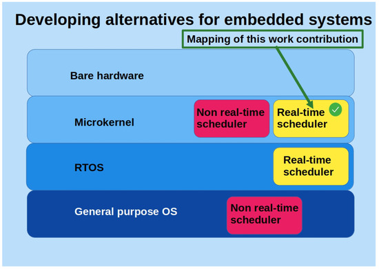
Figure 1.
Mapping of this work’s contribution.
It should be noted that other microkernels were also considered in this work. However, they were discarded because they did not have a hard real-time scheduler and were not easily adaptable for conversion to RTOS.
The new real-time microkernel mentioned above is presented in this paper, along with an initial evaluation of its performance, in accordance with the aforementioned most outstanding research lines in microkernels and RTOSs—specifically, the research line “(4) performance analysis and testing”. The developed microkernel, which we have named (Another Microkernel), has the initial objective of supporting the software components of a mobile autonomous robot.
In summary, the contributions of this work are as follows:
- Development of a microkernel for the dsPIC33E microcontroller family.
- The microkernel uses PS combined with ICPP as a real-time algorithm to schedule processes.
2. Materials and Methods
The materials and methods used in the development of AK are briefly described below.
2.1. Material Resources
- A printed circuit board (PCB) containing the dsPIC33EP512GM604 microcontroller (see Figure 2). This PCB was built in this work.
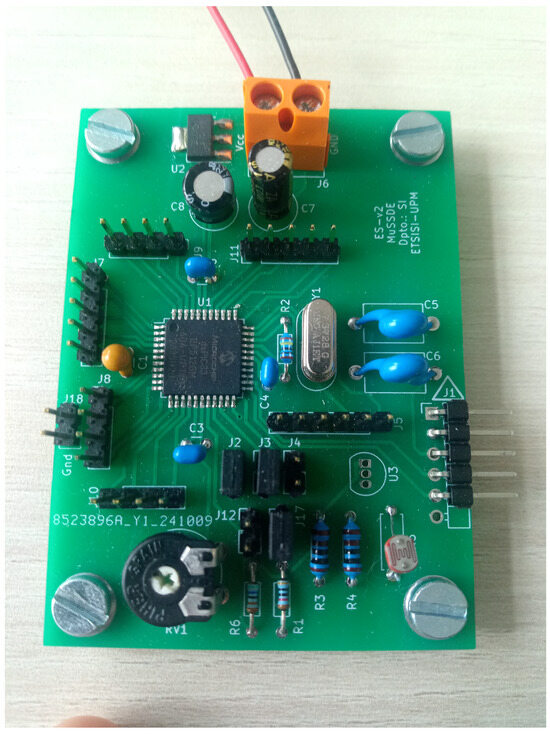 Figure 2. PCB with dsPIC33EP512GM604 used for developing and testing AK.
 - A Microchip Technology Inc. PICkit4 (Chandler, AZ, USA) in-circuit debugging probe.
- A RND 320-KA3005P (Nänikon, Switzerland) power supply.
- A SIGLENT SDS 1102CML+ (Shenzhen, China) dual-channel oscilloscope.
- A FLUKE 8846A multimeter (Everett, WA, USA).
It is noteworthy that the aforementioned tools have been utilized in the context of AK development. However, when using AK, the PICkit4 probe (or equivalent) is also required. This probe facilitates the transfer of code generated by the compiler to the microcontroller.
2.2. Software Resources:
- MPLAB X (v6.20) development environment (this software was used in its Linux version).
- XC16 (v2.10) compiler (this software was used in its Linux version).
It should be noted that the aforementioned software tools were utilized in the development of AK. However, they are also required to use AK. These tools are provided at no cost by the manufacturer of the dsPIC33E family of microcontrollers (Microchip Technology Inc.).
2.3. Methodological Approach
The most important methodological guidelines followed in the development of AK are those listed below:
- Life cycle: Incremental developments have been selected as the life cycle for AK development. The following objectives were set for each of the development cycles.
- (a)
- Select an alternative to perform context switching.
- (b)
- Select an alternative to obtain exclusive access to shared variables inside AK.
- (c)
- Incorporate counting semaphores.
- (d)
- Incorporate mutexes.
- AK Service testing: White-box testing was selected as the method for evaluating each of the services offered by AK. These tests were carried out to obtain satisfactory evidence of the functioning of each of the AK services.
- Performance analysis: Performance testing was centered on assessing the temporal behavior of the services provided by AK. In this same section, current consumption tests were performed in relation to the microcontroller’s clock frequency. The objective of these tests was to obtain satisfactory assurance of AK’s suitability for use in solving real-life engineering problems.
3. Results
Before starting this section, we would like to point out that the AK (version 1.5j) code is available for anyone who wants to use it [41].
3.1. Main Characteristics of AK
The main characteristics of AK are as follows:
- The real-time scheduling algorithm is PS combined with ICPP. This choice provides an equal or better performance than PS combined with PIP or PS combined with OCPP (often used in other RTOSs) and is easy to program.
- Running processes are not allowed to request dynamic memory (unless they create another process, which is possible, but not recommended).
- Semaphores and mutexes are provided as tools for process synchronization and resource sharing.
- No specific tool is provided to communicate processes.
- The maximum number of processes that AK can handle is set along with the compile time. It is configurable, and in this work, it is ten by default.
Below, we provide some explanations for the previous characteristics.
- I
- With respect to characteristic 1, some real-time microkernels offer policies for shared resource-locking, such as PIP or even OCPP. However, it is not common to find microkernels that offer ICPP. In this regard, ICPP achieves less than or an equal number of context switches as PIP or OCPP in the priority inversion scenario. In addition, ICPP has the advantage of being much easier to program than PIP and OCPP. The above-stated reasons justify the selection of ICPP.
- II
- Regarding characteristic 2, it is important to note that certain standards for developing high-integrity systems do not recommend the use of dynamic memory, at least for systems that require the highest level of integrity (IEC-61508, DO-178C, ISO 26262, EN 50128, etc.).
- III
- With respect to characteristic 3, semaphores are basic tools that are frequently used for the synchronization of processes, and mutexes are in fact mandatory when using ICPP.
- IV
- In relation to characteristic 4, currently, processes can communicate with each other using shared variables protected by mutexes. This is adopted strictly for the sake of simplicity. However, based on the synchronization tools that are already available in AK, it is not particularly difficult to build communication tools that can add value to the shared variables alternative. For example, mailboxes and monitors, among other tools, can be included in later versions of AK.
- V
- Finally, characteristic 5 greatly simplifies the design of AK. In addition, it makes AK more efficient by allowing it to declare some of its structures statically instead of forcing all of them to be dynamic, and facilitates the verification and validation of the systems developed on top of AK.
3.2. AK High-Level Architecture Design
The schematic block diagram in Figure 3 shows one of the possible views of the interacting elements within AK. The main aspects of this figure are explained below:
- Interface services: This component (see Figure 3, first row) contains all AK services that can be called from the outside. It is of particular interest for “mutex” because it implements the ICPP locking policy.
- Internal services: This component (see Figure 3, middle row, last component) contains services that can only be invoked from within AK. Of particular note is the scheduler, which implements PS.
- Data structures: This component (see Figure 3, middle row, first element) contains data structures required by other AK components.
- Task queue services: AK includes the services encapsulated in this component (see Figure 3, bottom left) to manage process queues. It is common in microkernels to have to manage process queues for various reasons, such as processes that are ready to run, processes that are blocked in a semaphore, etc.
- Hardware abstraction layer (HAL): This component (see Figure 3, bottom right) encapsulates some elements that depend on the programming model of the hardware on which AK is to run. It consists of a set of functions coded in an assembler, the most important of which is the processing of the Timer 1 interruption. This interruption is responsible for keeping the tick counter up to date and for calling the task scheduler. Another feature that stands out is the handling of the external interrupt 2 (INT2). In short, INT2 is used as a software interrupter in case a context switch needs to be performed before the next Timer 1 interruption will be activated.
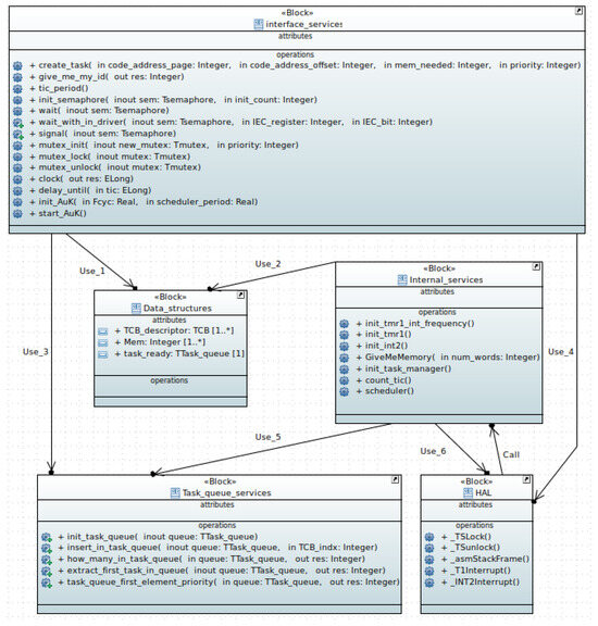
Figure 3.
A static view of AK’s high-level architectural design.
3.3. AK Interface
The AK interface consists of initial use services, synchronization tools, services for real-time systems, and additional services. We briefly describe this interface below.
3.3.1. Initial Use Services
- init_AuK
- It allows us to indicate the frequency with which the scheduler will be activated.
- create_task
- It allows the creation of processes.
- start_AuK
- Its execution causes the microkernel to start working.
3.3.2. Synchronization Tools
- Counting Semaphores
- They have the particularity of ordering the blocked processes by priority, and FIFO order within the same priority.
- init_semaphore
- It allows to initialize a semaphore indicating the value at which its event counter starts working.
- wait
- It allows to capture an event associated with a semaphore. The semaphore counter is decremented by one, unless it has already counted zero events, in which case it is not decremented and the calling process is blocked.
- wait_within_driver
- This service works in the same way as the previous one, but enables the interrupt specified as a parameter at the end of its execution. This simplifies the development of device drivers that need to share a semaphore with an interrupt handler.
- signal
- It allows to generate an event associated with a semaphore. If the semaphore event counter is greater than zero, it is incremented by one. If it is equal to zero, it is incremented if there are no blocked processes in the semaphore; otherwise, the highest-priority process that has been blocked for the longest time is unblocked.
- Mutex
- This makes it possible to work with persistent resources that are shared between processes according to the ICPP scheduling algorithm.
- mutex_init
- Initializes a mutex, and its priority must be configured as the highest priority of the processes that can use it (required by the ICPP algorithm).
- mutex_lock
- It allows us to acquire a shared resource for exclusive use. When a process acquires a mutex, due to ICPP scheduling algorithm being enforced, the process priority is updated with that of the mutex. This significantly and predictably reduces the length of time for which a process can cause a priority inversion.
- mutex_unlock
- It allows us to free a shared resource that had been acquired with mutex_lock and the process recovers the previous process priority.
3.3.3. Services for Real-Time Systems
- clock
- It returns the length of time for which the system has been running in ticks, since AK was started. A tick is the time interval between two process scheduler activations.
- delay_until
- It allows a process to be blocked until a specified time (tick) is reached. This service is essential for real-time tasks with periodic activation.
3.3.4. Additional Services
- give_me_my_id
- It supplies the process identifier to the invoking process.
- tic_period
- It indicates how much time elapses, in seconds, between consecutive activations of the scheduler.
3.3.5. General Considerations
In this work, AK aims to be a simple and efficient hard real-time microkernel. Therefore, to simplify its design, AK does not allow nested interrupts. This suggests that the AK user must implement development alternatives that ensure prompt attention to interrupting peripheral devices. A common approach is to ensure that interrupt treatments are kept to a minimum, ensuring that essential interruptions are not delayed by less significant ones. This traditional approach dictates that interrupt processing dedicates its resources exclusively to the storage of essential information and initiates the appropriate device driver to execute the tasks associated with that interrupt. This driver will be a task running on AK and therefore will have whatever priority the engineer deems appropriate. The priority of the device drivers should allow each device to be served in a timely manner.
The wait_within_driver service is provided to support the above scenario. Therefore, the software created by the programmer must follow the procedure shown below, in the suggested order:
- The peripheral interrupt is not allowed initially.
- The peripheral driver blocks itself on a semaphore using wait_within_driver, which as a last action enables the peripheral interrupt.
- When the peripheral interrupt is triggered, the device interrupt handler saves the essential data, disables the peripheral interrupt, and sends a signal to the semaphore on which the peripheral driver is blocked.
- The peripheral driver wakes up and finishes processing the information associated with the interrupt. It then returns to step 2, and steps 2 through 4 are repeated in an infinite loop.
Regarding reentrancy, it is well known that allowing nested interrupts increases the probability of harmful consequences due to a reentrancy scenario. In addition, the fact that nested interrupts are not allowed does not guarantee that there will not be harmful consequences due to a reentrancy scenario if exclusive access services are allowed to be used within peripheral device interrupts. However, if an interrupt handler and a device driver must synchronize using a semaphore, following the above procedure (i.e., the four steps mentioned above and in the suggested order) eliminates the possibility of harmful reentrancy.
3.4. AK Performance
We present the following performance tests because they may be useful to engineers who need to perform a schedulability analysis of systems developed using AK. The parameters considered for the performance tests, under specific experimental conditions, were as follows:
- The context-switching interval
- represents the time that elapses between the process being executed being ejected from the CPU and the moment that the new selected process starts executing. It should be noted that with a priority-based scheduling algorithm, it is very common for the newly selected process to be the same process that was running at the time the scheduler was invoked. This scenario is handled very efficiently in .
- Processes CPU utilization
- is the percentage of time spent executing process code compared to the total time (the total time is the time spent executing processes plus the time spent on context switches by AK).
- Current consumption
- Current consumption detected in the system.
- Microkernel services time consumption
- is the time invested in executing the services provided by AK.
The tests performed to evaluate AK were of two types: (a) simulation tests, and (b) tests on a real device. The MPLAB X environment was used to perform the simulations. On the other hand, a microcontroller from the dsPIC33E family (dsPIC33EP512GM604) was used to perform the tests on a real device. A 7.3728 MHz quartz crystal was employed for the dsPIC33EP512GM604. This microcontroller has phase-locked loop (PLL) that allows the generation of clock signals with frequencies () ranging from 60 MHz to 120 MHz. All this is implemented starting from a frequency of 7.3728 MHz. Finally, the instruction cycle frequency is .
To measure the context-switching interval, , current consumption, , and processes CPU utilization, , a program was created with several processes running an empty infinite loop, each with the same priority (when using a priority-based scheduler with this configuration, the first process works indefinitely).
3.5. Context-Switching Interval
The was measured by simulation. To achieve this, was first configured in the simulator for each test case. Next, breakpoints were set at the beginning and end of the interrupt handler that triggered the execution of the task scheduler. The results obtained by measuring are shown in Table 3.
Table 3.
Values of interest when using A with a target scheduling period of 10 ms and all processes working with an infinite empty loop.
3.6. Process CPU Utilization
The activation period of the task scheduler, , to be used in control systems must be chosen considering the bandwidth of the system to be controlled. In the experiments carried out in this work (shown in Section 4) = 10 ms was chosen, because it represents a very generous margin for the speed control of the mobile robot used in this work, which is shown in Section 4.2. The init_AuK service was used for this purpose (see Section 3.3.1).
To calculate , we first obtained the true . This period may be somewhat different from that indicated at system start-up (see Table 3). From the obtained , and considering , we obtained (see (1)).
At this point, it is worth noting that processes in a real-time system often leave the CPU voluntarily before expires. However, this was not the case in this work. In this study, to highlight the impact of the process scheduler on the overall system performance, the processes work within an infinite loop. The obtained values are shown in Table 3.
Looking at Table 3, we observe that is very high. This is due to the reduced impact that has on , with respect to the impact that has.
3.7. Current Consumption
Current consumption was measured using the Fluke 8864A multimeter. The increase in as of the device is increased (see Table 3) is an expected effect of CMOS and other variants of this technology (Section III Chapter 5 in [42]). The information provided in Table 3 is for the study case presented in this paper. However, it allows the engineer to make a decision that can establish a trade-off between power consumption and the computational speed of the device. Nevertheless, the engineer has to keep in mind that they must configure AK [41] for their specific application and obtain the necessary measurements.
3.8. Time Consumed by the Execution of K Services
Most of the services provided by AK consume a few microseconds (Table 4). However, the situation may be slightly different for the services related to the use of semaphores: “wait” and “signal”. It is difficult for the response time of services associated with semaphores not to depend on the number of blocked processes in their queues, and the number of processes waiting to execute in the ready queue. In all these cases, the process must be queued in a manner that allows them to be sorted by priority, plus the FIFO order inside each priority. Such analysis may be relevant for hard real-time systems, at least to establish an upper bound on the response time. It is also necessary to understand the behavior of mutexes, since they are built into AK with semaphores.
Table 4.
Time consumed by services: = 119.808 MHz.
In Figure 4, the times consumed by the “wait” service in different situations are shown. The blue line shows the time consumed in executing the “wait” service by processes that do not block because the counter associated with the semaphore has a value greater than 0. In this case, the service never consumes more than 2.47 s [60 MHz, 120 MHz].
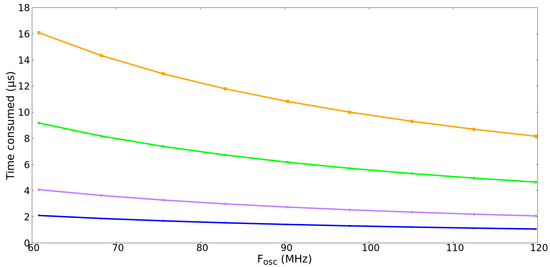
Figure 4.
Time consumed when executing “wait” vs. . Blue line: the process is not blocked. Purple line: the process is blocked and there were already blocked processes in the semaphore but of lower priority. Green line: the process is blocked and there were already four blocked processes in the semaphore of higher or equal priority. Orange line: same as the green line but with nine blocked processes in the semaphore.
The purple line in Figure 4 represents the time consumed in the “wait” service when the process is blocked. At this point, it is worth mentioning that there are already blocked processes in the same semaphore, but they have a strictly lower priority than the currently blocked process.
The green line in Figure 4 represents a situation in which a new process is blocked. However, there are already four previously blocked processes, and they have the same or higher priority than the new blocked process. Finally, the orange line represents the same situation as the green line, but this time, the number of previously blocked processes is equal to nine. This is the worst-case scenario for ten tasks, which is the default configuration of AK.
Figure 5 shows the time that has elapsed from the invocation of “signal” to its termination, in different scenarios and with different . The blue line represents the most advantageous case, because the process executes the “signal” service, with the semaphore counter having a value greater than zero. The orange line represents the second most advantageous case. This shows the situation of a process running “signal” when the counter associated with the semaphore is equal to zero and there are no blocked processes in the semaphore. Finally, the worst-case scenario is shown by the red line, because it is more time-consuming. Specifically, in this case, nine tasks have been deemed ready to be executed within and at this instant “signal” wakes up a tenth task that has a lower priority than the previous nine.
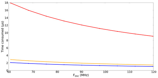
Figure 5.
Time consumed when executing “signal” vs. . Blue line: Case in which the semaphore counter was already greater than zero. Orange line: case in which the semaphore counter was at zero, but there were no blocked processes. Red line: case in which, having previously woken up nine processes of a semaphore, “signal” wakes up a new process that has a lower priority than all the previous ones.
Finally, Table 4, Figure 4 and Figure 5 provide the engineer with information that facilitates the schedulability analysis of real-time systems. With the curves shown in the figures and the information in the table, the worst-case execution time can be found, allowing a rigorous determination of whether a real-time design is schedulable.
4. Application Examples with AK
Two application examples are presented below. The first is a practical example that allows the operation of AK to be observed. And the second is the prototype design of the control level of a mobile autonomous robot, built in this work. In short, the first example is trivial and the second is more complex. Regarding the first example, we want to provide a low-complexity educational introduction to the use of AK. With the second example, however, we want to demonstrate the usefulness of AK for real-world problems, such as developing the control layer of an autonomous mobile robot. In this case, AK is used to execute two processes with real-time constraints (i.e., Speed_controller and Pos_Att_recorder) along with another sporadic activation process (i.e., Communications).
There are different alternatives to check if a real-time system is feasible. One alternative is to check that all the processes of a system meet their response times before the period in which each process must be activated expires. In this regard, and according to Chapters 11.8 and 11.9 in [8] and Chapter 7.9 in [6], Definition 1 is presented below.
Definition 1.
Given a set of processes where , , where n is the maximum number of processes with real-time constraints, P is said to have the schedulability property if , where is the response time of , and is the activation period of .
Remark 1.
If of Definition 1 is calculated using the iterating Equation (2), then the condition stated in Definition 1 is of sufficiency and (2) is imposed by ICPP.
where , is the computation time of , is the maximum blocking time of when trying to use resources that could have been acquired by lower-priority processes (see (3)), is the set of indices representing processes with higher priority than , is the activation period of , and is the value of at the r-th iteration.
where is the maximum computational time required by using resource k shared with , and represents the set of system processes with lower priority than .
4.1. First Example
It will be considered that = 119.808 MHz and = 200 s, which is a very small and unusual period, which is nevertheless adequate for the experiment to be performed, although it significantly reduces the .
In this example, two processes are created, one with real-time constraints that must be activated every 200 s, and the other without real-time constraints. The first process executes a loop of one hundred iterations changing the state of pin RC6 of the dsPIC33EP512GM604. On the other hand, the second process writes changes to pin RC7 indefinitely.
The main program of this example is as follows:
int main(void)
{
int x;
⠀
// Fosc = 119.808 MHz,
// then Fcy = Fosc/2 = 59.904 MHz
init_clock_signal();
init_ports();
⠀
x = init_AuK(59.904E+6, 0.0002);
⠀
if(x == 0)
{
id1 = create_task(
__builtin_tblpage(task_RT),
__builtin_tbloffset(task_RT), 70, 5);
⠀
id2 = create_task(
__builtin_tblpage(task_N_RT),
__builtin_tbloffset(task_N_RT), 70, 3);
⠀
start_AuK();
}
⠀
// This instruction will never be executed.
Sleep();
}
This code shows how simple it is to initialize the microkernel, create processes, and start the microkernel. The init_clock_signal() function is external to AK and its purpose is to set the clock signal to the value indicated in the preceding comment. The init_ports() function is also external to AK and is responsible for configuring the RC6 and RC7 pins as digital output pins. Next, init_AuK initializes the microkernel by imposing = 200 s. The create_task service is invoked twice to create the two proposed processes. Priority 5 is assigned to the first process, and priority 3 is assigned to the second process. Finally, the start_AuK service starts the microkernel.
The function containing the process code with real time constraints is as follows:
void task_RT()
{
int x;
unsigned long wake_up_time, task_period;
⠀
task_period = 1; // 0.2 ms
⠀
wake_up_time = clock();
⠀
while(1)
{
for(x = 0; x < 100; x++)
PORTCbits.RC6 = !LATCbits.LATC6;
⠀
wake_up_time += task_period;
delay_until(wake_up_time);
}
}
The most important part of the above code is the following: inside an infinite loop, the 100 update cycles of the RC6 pin are executed, and then the process sleeps until the next instant when it should operate.
The function containing the code without real-time constraints is as follows:
void task_N_RT()
{
while(1)
PORTCbits.RC7 = !LATCbits.LATC7;
}
The most important thing here is that this process operates as long as it is permitted by , being in permanent execution unless it is expelled by the first process, which is of higher priority.
A SIGLENT SDS 1102CML+ oscilloscope screenshot of the operation of the example presented in Section 4.1 is shown in Figure 6. In this figure, the cycles of the real-time process are shown in yellow, and those of the system without time constraints are shown in purple. As can be seen, the process with real-time constraints is executed every 200 s (see the legend on the top left, constructed from the position of the vertical cursors and shown with a white dashed line). The process without real-time constraints is executed when the previous one enters in sleep state. This figure shows that the program proposed in this section has been recorded on the dsPIC33EP512GM804 and that it works satisfactorily, as expected.
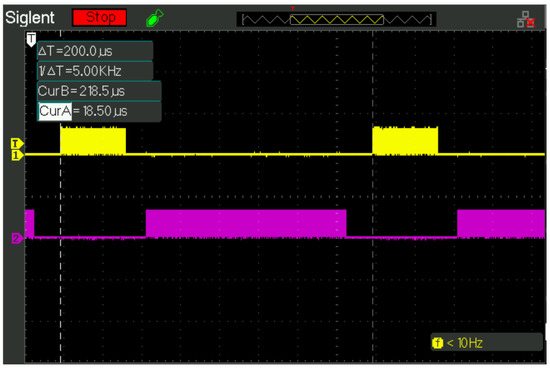
Figure 6.
Oscilloscope image of the program execution. Yellow color: cycles of the real-time process. Purple color: cycles of the system without time constraints. White dashed lines: vertical cursors, indicating distance between cycles of the real-time process according to the set period (200 s).
Lemma 1.
According to Definition 1, the example shown in Section 4.1 is schedulable.
Proof.
Since there is only one process with real-time constraints, and there are no resources shared with other processes, to comply with Definition 1 it is sufficient that . This is because there is no interference with higher-priority processes, nor is there priority inversion with lower-priority processes. So, in this case, (see (2)), s and s. Then, (see yellow signal in Figure 6) and therefore the system is schedulable. □
4.2. Second Example
Autonomous mobile robots are becoming increasingly relevant in a variety of areas, including domestic and industrial contexts [43,44,45].
In this example, we present a real-world application where AK is used to program a software entity of an autonomous robot. In this case, the software architecture follows a layered organization with four fundamental components: Governance, Navigation, Control, and Perception. Each of these components represents one layer of the architecture.
In short, each of the components is responsible for the following tasks: (1) Governance is responsible for ordering the overall behavior of the robot. When the Governance component determines that the robot should move, it indicates this to the Navigation component. This is achieved by providing the coordinates and the final orientation to be reached in the movement. (2) Navigation is responsible for determining the route to be followed by the robot, once the command has been received from the Governance component. When the route has been determined, Navigation sends commands to the Control component to trigger the actual movement of the robot. (3) Control is responsible for executing the robot’s feedback velocity controller according to the commands set by the Navigation component. (4) Perception is responsible for providing information about the robot’s environment and its internal state, with Navigation being its main client.
In this applied research, one microcontroller has been considered for the Control component, one for the Perception and Navigation components, and one for the Governance component. Figure 7 shows the CAD design of the robot, and Figure 8 shows its construction. The robot shown in Figure 8 is a prototype to test proposals that may arise in the service robotics domain. In addition, Figure 9 shows the high-level software architecture of the Control component (SysML notation). For the purposes of this paper, it does not make detailed contributions to the rest of the components. We show the Control component because it has the characteristic of having a strict real-time process to execute the speed controller. If the activation period of the speed controller is not met, the behavior of the robot could tend toward instability.
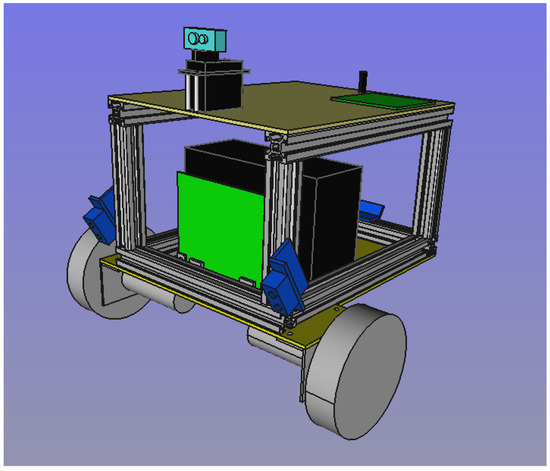
Figure 7.
CAD global design of the autonomous robot prototype.
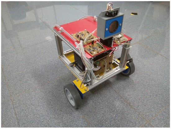
Figure 8.
Autonomous robot prototype.
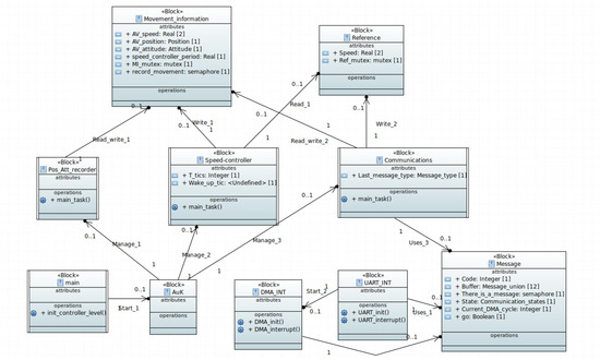
Figure 9.
Architectural design by means of SysML block diagram of the control level of the autonomous mobile robot.
The blocks with double sidebars shown in Figure 9 are understood to be active and, except for the “main” block, actually correspond to processes to be created on AK.
Speed_Controller (Figure 9) is a strict real-time process which is designed to be triggered every 50 ms. Each time it is activated, it queries the speed setpoint in the Reference block (Figure 9) and acts on the motors to eliminate the speed error. Pos_Att_Recorder (Figure 9) calculates the current position and orientation of the robot. To this end, motor odometry information is used. Pos_Att_Recorder is a process that is activated with the same frequency as Speed_Controller. Finally, Communications (Figure 9) manages the communications between the Control component and the Navigation component. The Navigation component is not referred to in Figure 9 because it is located in another microcontroller.
The Navigation component consults the position and orientation estimation maintained by the Control component to verify compliance with the proposed route. This component is updated with information it can obtain from the physical environment, thanks to the Perception component. Navigation can modify the position and orientation estimated by the Control component, if it considers that the error is significant. In addition, the Navigation component, as indicated above, can modify the speed setpoint in the Control component.
Lemma 2.
According to Definition 1, the example shown in Section 4.2 is schedulable.
Proof.
There are three processes in the system:
Speed_controller and Pos_Att_recorder are two real-time processes, and Communications is a sporadically triggered, non-real-time process. Communications can generate a maximum blocking time by priority inversion of s to the Speed_controller and Pos_Att_recorder processes. This short blocking time is achieved because the communications component benefits from the fact that the data transfer to and from the microcontroller, which is responsible for the navigation software, is performed via the Direct Memory Access (DMA) device. In the dsPIC33E family, the SRAM memory is dual-ported and the DMA device operates with independent data and address buses without affecting CPU operation (see Chapter 22.1 in [46]). In addition, the activation period of the real-time processes is ms. Also, the computation time of the speed controller is s, and that of the position and attitude recorder is s. Then, substituting the above data into (2), we obtain , and , where . Therefore, the system is schedulable. □
Finally, we end this section by mentioning that the communications protocol between the navigation level and the control level is orchestrated by the Communications process. However, this protocol is distributed among the Communications process, interrupt treatments (i.e., UART_INT and DMA_INT)) and a data structure (i.e., Message).
Lastly, it is worth noting that the speed controller used was a multivariable PID controller whose reference signals were longitudinal velocity and angular velocity. In addition, the tuning of this controller was performed using a classical procedure that seeks maximum gain without unstable behavior, no steady-state error, and a reasonably short rise time without overshoot.
5. Discussion
AK, like most microkernels, arises to enable the development of embedded software systems where it is advantageous to design these systems using a process model. The processes that perform over AK could have hard real-time constraints [47], but they do not need the extras that are usually provided by RTOSs.
In addition to the above, in this work, AK has been the solution to the need to develop mobile autonomous robots. However, nothing prevents it from being used in other embedded systems.
AK implements PS in combination with ICPP. In the examples presented in this work, RMS is used as a particular alternative inside PS. The ICPP algorithm has the following advantages: (1) it is simple to program, despite having a non-trivial formalism, and (2) if a process blocks because of priority inversion, then it will block only once in each actuation period. Point 2 above will occur at the beginning of the period in which the process is blocked.
ICPP allows a design-time schedulability analysis of the system. This constitutes a sufficient, but not necessary, formal proof of good real-time performance [6,8].
At this point, it is worth noting that there are RTOSs that have very good schedulers that facilitate the development of “hard real-time systems”. Some of the most outstanding ones are mentioned below.
RTEMS (Real-Time Executive for Multiprocessor Systems) (https://ftp.rtems.org/pub/rtems/releases/5/5.1/docs/html (accessed on 26 April 2025)) implements PS combined with ICPP. However, it is oriented towards devices closer to processors (i.e., x86, RISC-V, LEON, PowerPC, etc.). Furthermore, in the microcontroller world, RTEMS supports ARM architectures. However, it does not support dsPIC33EP and similar families.
Erika Enterprise (https://www.erika-enterprise.com/ (accessed on 26 April 2025)) and Trampoline (https://github.com/TrampolineRTOS/trampoline (accessed on 26 April 2025)) also implement PS combined with ICPP. They aim to comply with the OSEK/VDX and AUTOSAR OS standards. These standards are designed for the automotive industry and allow collaborative development of electronic control units (ECUs) to take place. Erika Enterprise and Trampoline are a very high-quality RTOSs, but are closely related to the automotive industry and require a rigorous and elaborate configuration procedure for projects developed with them with the aim of accommodating very different companies with different visions and ways of developing projects. Therefore, they are quasi-specific-purpose RTOS.
Unlike the RTOSs mentioned before, FreeRTOS (https://www.freertos.org/Documentation/RTOS_book.html (accessed on 26 April 2025)) implements PIP instead of ICPP. Other notable RTOSs that also implement PIP include the following: Nuttx, Embox, RT-Thread, MynewT, Distortos, and so on. However, FreeRTOS benefits from having a large community of users, which is not the case with other RTOSs. The fact that FreeRTOS implements PIP makes it a poor candidate for our study case because ICPP allows the affected priority inversion process to be blocked only once, as stated in previous paragraphs in this section. On the other hand, PIP allows a higher-priority process to be blocked several times by priority inversion within its actuation period.
Finally, the present study does not consider more recent proposals for newer real-time locking protocols for shared resources because, to the authors’ knowledge, there have been no significant advances in this topic subsequent to ICPP.
What has been said in this section justifies the construction of K, with a view to providing a solution not only to specific robotics problems, but also to problems in the field of embedded systems.
6. Conclusions
This paper has presented a real-time microkernel with a hardware abstraction layer oriented to run on the dsPIC33E family of microcontrollers. In addition, it has been provided with a scheduler and the necessary process synchronization tools that implement the ICPP.
It is true that nowadays, there are many freely distributed RTOS with excellent performance. However, we thought that adapting an RTOS to a new real-time scheduler could be complex due to the side effects to be considered. Therefore, in our study, it turned out to be more efficient to create a microkernel than to adapt an existing RTOS, since the latter has functionalities that we do not need and whose customization would have required unnecessary work.
In this paper, the benefits of were verified in an autonomous robot prototype whose purpose was to test software architectures for autonomous behavior. This is of interest because provides a higher level of abstraction than that required to work on a bare machine.
As future work, we are currently evaluating, from an operational safety perspective, the advantages and disadvantages of allowing processes to acquire and release memory at runtime, rather than forcing the programmer to manage the available memory without microkernel support.
Author Contributions
Conceptualization, W.H. and N.C.; methodology, W.H. and N.C.; software, W.H. and N.C.; validation, W.H. and N.C.; formal analysis, W.H. and N.C.; investigation, W.H. and N.C.; resources, W.H. and N.C.; writing—original draft preparation, W.H. and N.C.; writing—review and editing, W.H. and N.C.; visualization, W.H. and N.C.; supervision, W.H. and N.C.; project administration, W.H. and N.C.; funding acquisition, W.H. and N.C. All authors have read and agreed to the published version of the manuscript.
Funding
This research was funded by Universidad de las Americas, Ecuador, under the research project IEA.WHP.23.13.01, and the APC was funded by Universidad de las Americas, Ecuador.
Institutional Review Board Statement
Not applicable.
Informed Consent Statement
Not applicable.
Data Availability Statement
The real-time microkernel for the dsPIC33E family developed in this work is available to the public. For further details, please refer to reference [41] of the paper.
Conflicts of Interest
The authors declare no conflicts of interest.
Abbreviations
The most relevant abbreviations used in this work are listed below.
| AK | Another microkernel. |
| AUTOSAR | AUTomotive Open System ARchitecture. |
| CMSIS | Common Microcontroller Software Interface Standard. |
| CPU | Central Processing Unit. |
| DMA | Direct Memory Access. |
| DMS | Deadline monotonic scheduling. |
| FPGA | Field Programmable Gate Array. |
| ICPP | Immediate ceiling priority protocol. |
| OCPP | Original ceiling priority protocol. |
| OSEK | Offene Systeme und deren Schnittstellen für die Elektronik in Kraftfahrzeugen. |
| PIP | Priority inheritance protocol. |
| PS | Priority scheduling. |
| RMS | Rate monotonic scheduling. |
| RTOS | Real-time operating system. |
| VDX | Vehicle Distributed eXecutive. |
References
- Silberschatz, A.; Galvin, P.B.; Gagne, G. Operating Systems Concepts, 10th ed.; Wiley: New York, NY, USA, 2018. [Google Scholar]
- Craig, I.D. Formal Models of Operating System Kernels; Springer: Berlin/Heidelberg, Germany, 2007. [Google Scholar]
- Xu, R.; Zhang, L.; Ge, N. Modeling and Timing Analysis for Microkernel-Based Real-Time Embedded System. IEEE Access 2019, 7, 39547–39563. [Google Scholar] [CrossRef]
- Liu, J.W.S. Real-Time Systems; Prentice Hall: Hoboken, NJ, USA, 2000. [Google Scholar]
- Laplante, P.A.; Ovaska, S.J. Real-Time Systems Design and Analysis. Tools for the Practitioner; IEEE Press: Piscataway, NJ, USA; Wiley: New York, NY, USA, 2012. [Google Scholar]
- Buttazzo, G.C. Hard Real-Time Computing Systems. Predictable Scheduling Algorithms and Applications; Springer: Berlin/Heidelberg, Germany, 2011. [Google Scholar]
- Cottet, F.; Delacroix, J.; Kaiser, C.; Mammeri, Z. Schedulling in Real-Time Systems; John Wiley and Sons: New York, NY, USA, 2002. [Google Scholar]
- Burns, A.; Wellings, A. Real-Time Systems and Programming Languages; Addison-Wesley: Boston, MA, USA, 2009. [Google Scholar]
- Joseph, M. (Ed.) Real-Time Systems Specification, Verificationi and Analysis; Prentice Hall: Boston, MA, USA, 1996. [Google Scholar]
- Ramegowda, D.; Lin, M. Energy efficient mixed task handling on real-time embedded systems using FreeRTOS. J. Syst. Archit. 2022, 131, 102708. [Google Scholar] [CrossRef]
- Zhang, Y.W.; Chen, R.K. A survey of energy-aware scheduling in mixed-criticality systems. J. Syst. Archit. 2022, 127, 102524. [Google Scholar] [CrossRef]
- Zhang, Y.W. DVFS-based energy-aware scheduling of imprecise mixed-criticality real-time tasks. J. Syst. Archit. 2023, 137, 102849. [Google Scholar] [CrossRef]
- Capota, E.A.; Stangaciu, C.S.; Micea, M.V.; Curiac, D.I. Towards mixed criticality task scheduling in cyber physical systems: Challenges and perspectives. J. Syst. Softw. 2019, 156, 204–216. [Google Scholar] [CrossRef]
- Zhang, Q.; Lin, M.; Yang, L.T.; Chen, Z.; Khan, S.U.; Li, P. A Double Deep Q-Learning Model for Energy-Efficient Edge Scheduling. IEEE Trans. Serv. Comput. 2019, 12, 739–749. [Google Scholar] [CrossRef]
- Awan, M.A.; Petters, S.M. Intra-task device scheduling for real-time embedded systems. J. Syst. Archit. 2015, 61, 321–340. [Google Scholar] [CrossRef]
- Dantas, L.P.; de Azevedo, R.J.; Gimenez, S.P. A Novel Processor Architecture With a Hardware Microkernel to Improve the Performance of Task-Based Systems. IEEE Embed. Syst. Lett. 2019, 11, 46–49. [Google Scholar] [CrossRef]
- Tang, Y.; Bergmann, N.W. A Hardware Scheduler Based on Task Queues for FPGA-Based Embedded Real-Time Systems. IEEE Trans. Comput. 2015, 64, 1254–1267. [Google Scholar] [CrossRef]
- Gaitan, V.G.; Gaitan, N.C.; Ungurean, I. CPU Architecture Based on a Hardware Scheduler and Independent Pipeline Registers. IEEE Trans. Very Large Scale Integr. (VLSI) Syst. 2015, 23, 1661–1674. [Google Scholar] [CrossRef]
- Rüetschi, A.; Syrpas, P.; Flak, B.; Tomzik, K.; Steimer, P.K. Heterogeneous Control Platform Design for Power Conversion Systems. IEEE Trans. Ind. Inform. 2022, 18, 2934–2942. [Google Scholar] [CrossRef]
- Arm, J.; Baštán, O.; Mihálik, O.; Bradáč, Z. Measuring the Performance of FreeRTOS on ESP32 Multi-Core. IFAC-PapersOnLine 2022, 55, 292–297. [Google Scholar] [CrossRef]
- Penna, P.H.; Souto, J.V.; Uller, J.F.; Castro, M.; Freitas, H.; Méhaut, J.F. Inter-kernel communication facility of a distributed operating system for NoC-based lightweight manycores. J. Parallel Distrib. Comput. 2021, 154, 1–15. [Google Scholar] [CrossRef]
- Serino, A.; Cheng, L. Real-Time Operating Systems for Cyber-Physical Systems: Current Status and Future Research. In Proceedings of the 2020 International Conferences on Internet of Things (iThings) and IEEE Green Computing and Communications (GreenCom) and IEEE Cyber, Physical and Social Computing (CPSCom) and IEEE Smart Data (SmartData) and IEEE Congress on Cybermatics (Cybermatics), Rhodes, Greece, 2–6 November 2020; pp. 419–425. [Google Scholar] [CrossRef]
- Kang, H.; Kim, K.; Jin, H.W. Real-Time Software Pipelining for Multidomain Motion Controllers. IEEE Trans. Ind. Inform. 2016, 12, 705–715. [Google Scholar] [CrossRef]
- García Villaescusa, D.; Aldea Rivas, M.; González Harbour, M. Response-time analysis of mesh-based many-core systems. J. Syst. Archit. 2023, 134, 102762. [Google Scholar] [CrossRef]
- Arlat, J.; Fabre, J.C.; Rodriguez, M. Dependability of COTS microkernel-based systems. IEEE Trans. Comput. 2002, 51, 138–163. [Google Scholar] [CrossRef]
- Ungurean, I. Timing Comparison of the Real-Time Operating Systems for Small Microcontrollers. Symmetry 2020, 12, 592. [Google Scholar] [CrossRef]
- Azimi, S.; De Sio, C.; Portaluri, A.; Rizzieri, D.; Vacca, E.; Sterpone, L.; Merodio Codinachs, D. Exploring the Impact of Soft Errors on the Reliability of Real-Time Embedded Operating Systems. Electronics 2023, 12, 169. [Google Scholar] [CrossRef]
- Lee, J.H.; Hyeon, B.S.; Jeon, O.Y.; Park, N.I. Analysis of real-time operating systems’ file systems: Built-in cameras from vehicles. Forensic Sci. Int. Digit. Investig. 2023, 44, 301500. [Google Scholar] [CrossRef]
- Delgado, R.; Jo, Y.H.; Choi, B.W. RT-AIDE: A RTOS-Agnostic and Interoperable Development Environment for Real-Time Systems. IEEE Trans. Ind. Inform. 2023, 19, 2772–2781. [Google Scholar] [CrossRef]
- Yoo, T.; Choi, B.W. Real-Time Performance Benchmarking of RISC-V Architecture: Implementation and Verification on an EtherCAT-Based Robotic Control System. Electronics 2024, 13, 733. [Google Scholar] [CrossRef]
- seL4 Performance. 2025. Available online: https://sel4.systems/About/Performance/ (accessed on 26 April 2025).
- ThreadX Documentation. 2025. Available online: https://github.com/eclipse-threadx/rtos-docs/blob/main/rtos-docs/threadx/index.md (accessed on 26 April 2025).
- Barry, R.; FreeRTOS. Mastering the FreeRTOS Real Time Kernel. A Hands-On Tutorial Guide; Version 1.1.0; Amazon.com: Washington, DC, USA, 2023. [Google Scholar]
- ERIKA Enterprise Manual. Real-Time Made Easy, version: 1.4.5.; Evidence Embedding Technology ed.; Evidence Srl: Pisa, Italy, 2012. [Google Scholar]
- Béchnnec, J.L.; Briday, M.; Faucou, S.; Molinaro, P.; Pavin, F. The Trampoline Handbook. Release 2.0. 2023. Available online: https://github.com/TrampolineRTOS/trampoline/tree/master/documentation/manual (accessed on 26 April 2025).
- seL4 Foundation. seL4 Reference Manual; Version 13.0.0; The seL4 Foundation: Sydnay, Australia, 2024. [Google Scholar]
- RTEMS. RTEMS Classic API Guide. Release 7.e8e6f12, RTEMS Project and contributors. 2025.
- NuttX Documentation. 2025. Available online: https://nuttx.apache.org/docs/latest/index.html (accessed on 26 April 2025).
- CMSIS-RTOS2 Version 2.2.0. Real-Time Operating System: API and RTX Reference Implementation. 2025. Available online: https://arm-software.github.io/CMSIS_5/develop/RTOS2/html/index.html (accessed on 26 April 2025).
- Levis, P.; Gay, D. TinyOS Programming; Cambridge University Press: Cambridge, UK, 2009. [Google Scholar]
- Hernandez, W.; Cañas, N. AμK Source Code. 2025. Available online: https://github.com/Norberto-CdP/AuK (accessed on 30 April 2025).
- Chen, W.K. (Ed.) The Electrical Engineerging Handbook; Elsevier Academic Press: Amsterdam, The Netherlands, 2004. [Google Scholar]
- Farina, M.; Shaker, W.K.; Ali, A.M.; Hussein, S.A.; Dalang, F.S.; Bassey, J.O. Automated guided vehicles with a mounted serial manipulator: A systematic literature review. Heliyon 2023, 9, e15950. [Google Scholar] [CrossRef] [PubMed]
- Liu, Z.; Liang, X.; Chen, X.; Wen, X. Design of a sweeping robot based on fuzzy QFD and ARIZ algorithms. Heliyon 2024, 10, e38319. [Google Scholar] [CrossRef]
- Patruno, C.; Renò, V.; Nitti, M.; Mosca, N.; di Summa, M.; Stella, E. Vision-based omnidirectional indoor robots for autonomous navigation and localization in manufacturing industry. Heliyon 2024, 10, e26042. [Google Scholar] [CrossRef] [PubMed]
- Section 22. Direct Memory Access (DMA). dsPIC33E/PIC24E Family Reference Manual. 2011. Available online: https://ww1.microchip.com/downloads/en/DeviceDoc/70182C.pdf (accessed on 12 May 2025).
- Kopetz, H. Real-Time Systems. Design Principles for Distributed Embedded Applications; Springer: Berlin/Heidelberg, Germany, 2011. [Google Scholar]
Disclaimer/Publisher’s Note: The statements, opinions and data contained in all publications are solely those of the individual author(s) and contributor(s) and not of MDPI and/or the editor(s). MDPI and/or the editor(s) disclaim responsibility for any injury to people or property resulting from any ideas, methods, instructions or products referred to in the content. |
© 2025 by the authors. Licensee MDPI, Basel, Switzerland. This article is an open access article distributed under the terms and conditions of the Creative Commons Attribution (CC BY) license (https://creativecommons.org/licenses/by/4.0/).