
Non-Invasive Voltage Measurement Device Based on MEMS Electric Field Sensor and Applications

 ,
,
Abstract
1. Introduction
2. Theoretical Approach
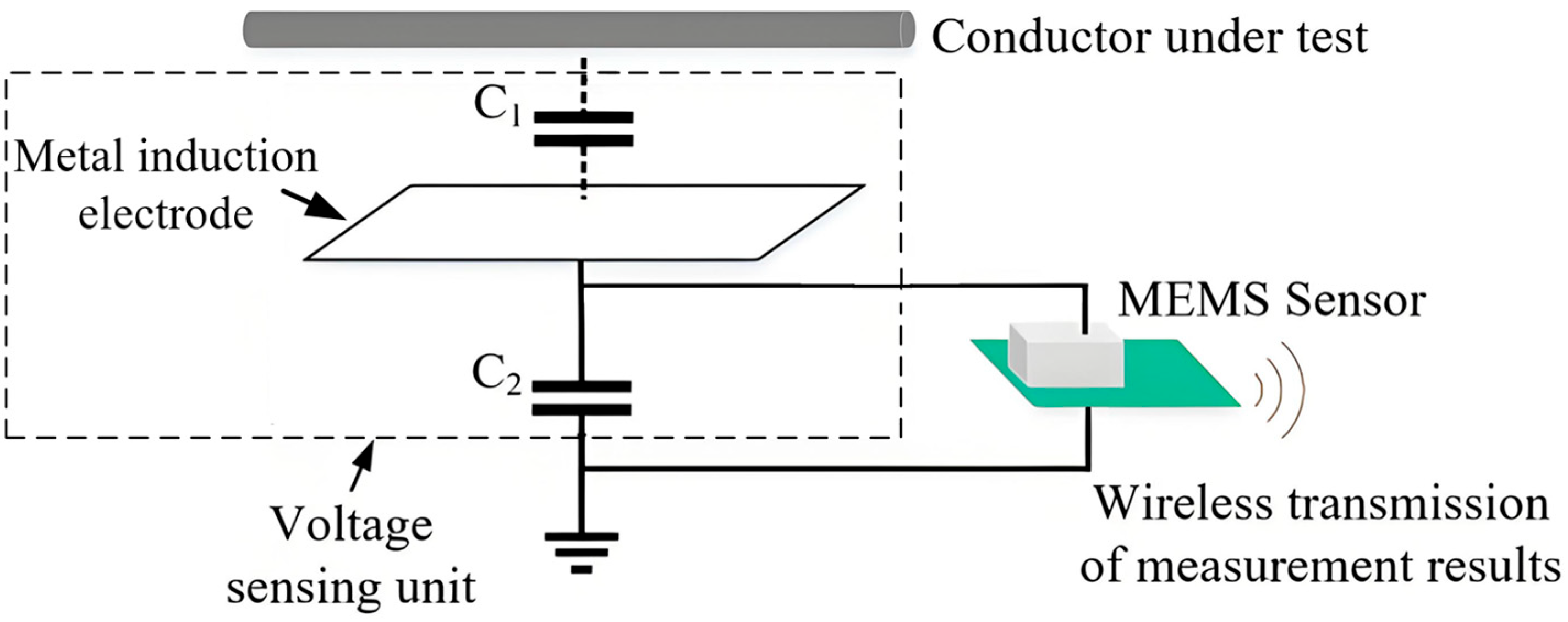
2.1. Voltage Measurement Principle
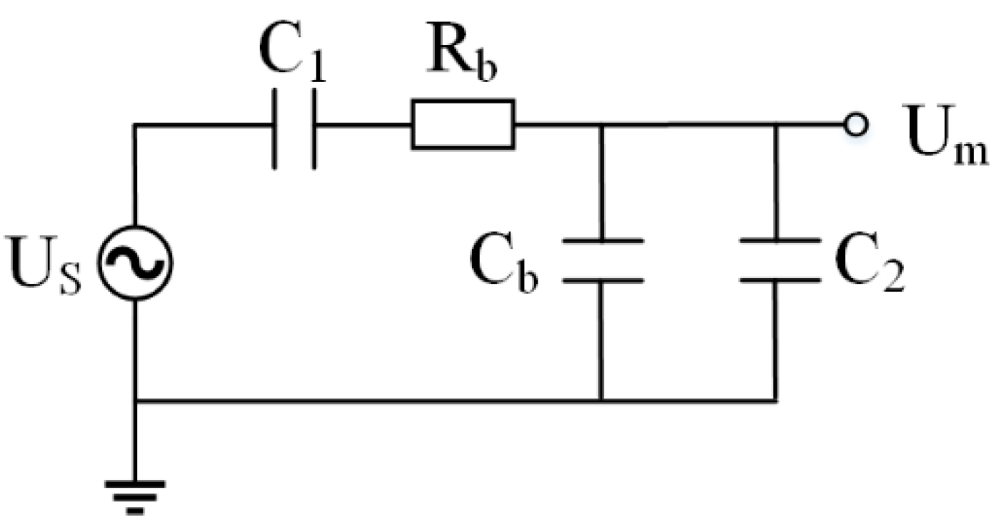
2.2. Circuit-Equivalent Model Analysis
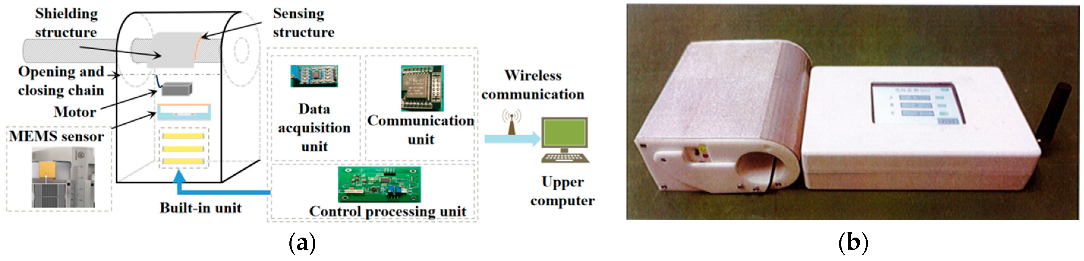
3. Measurement Device Design
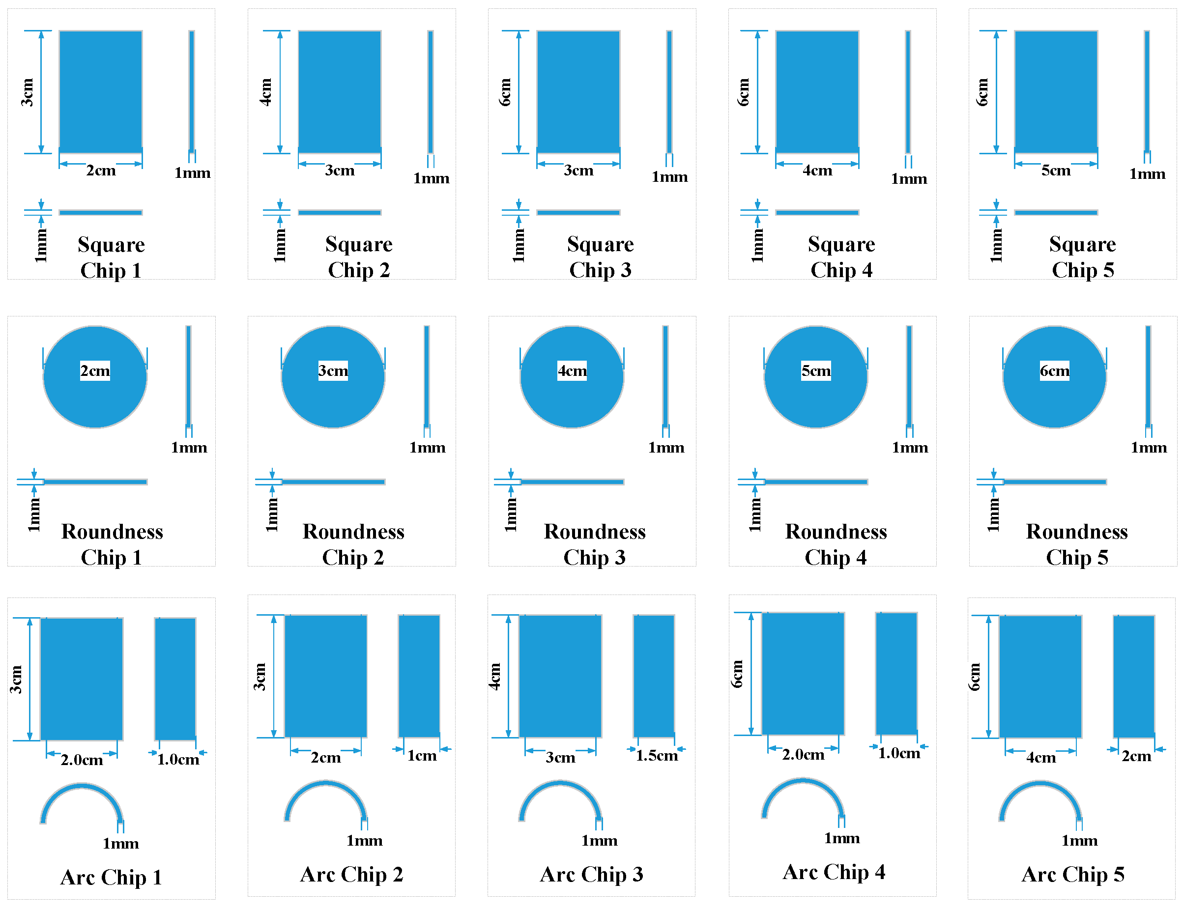
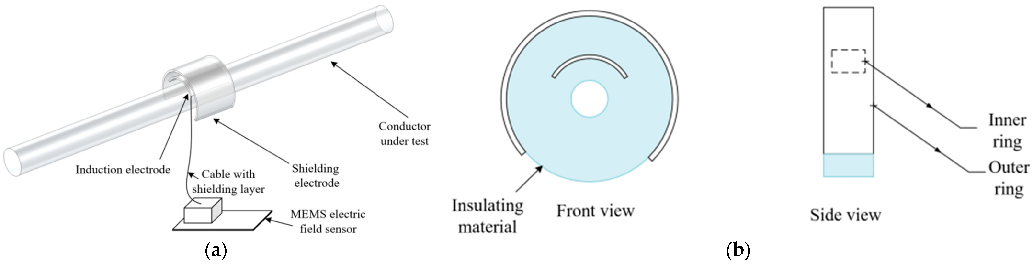
3.1. Design of Induction Structure
3.2. Design of Voltage Measurement Device
4. Experimental Test and Result Analysis
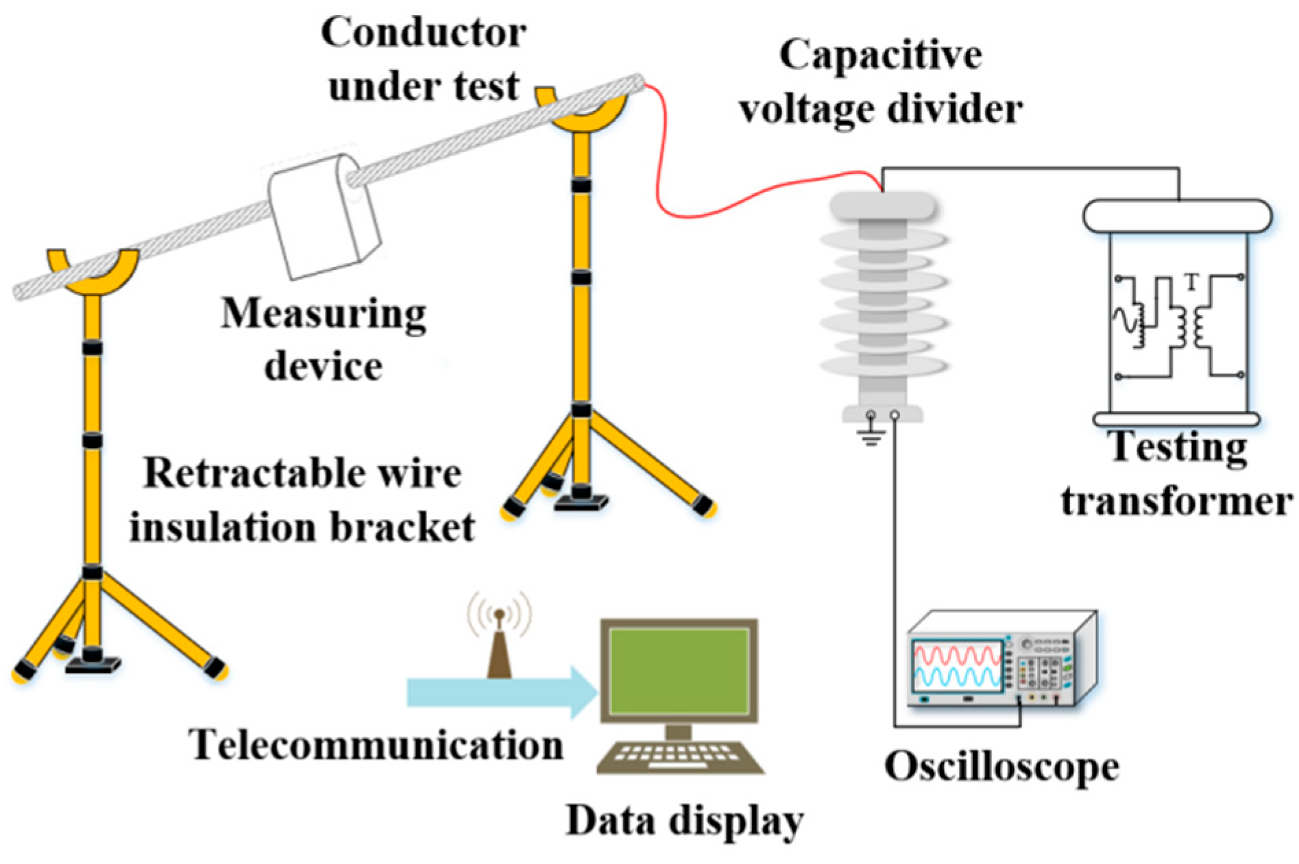
4.1. Construction of the Experimental Platform
4.2. Accuracy Test
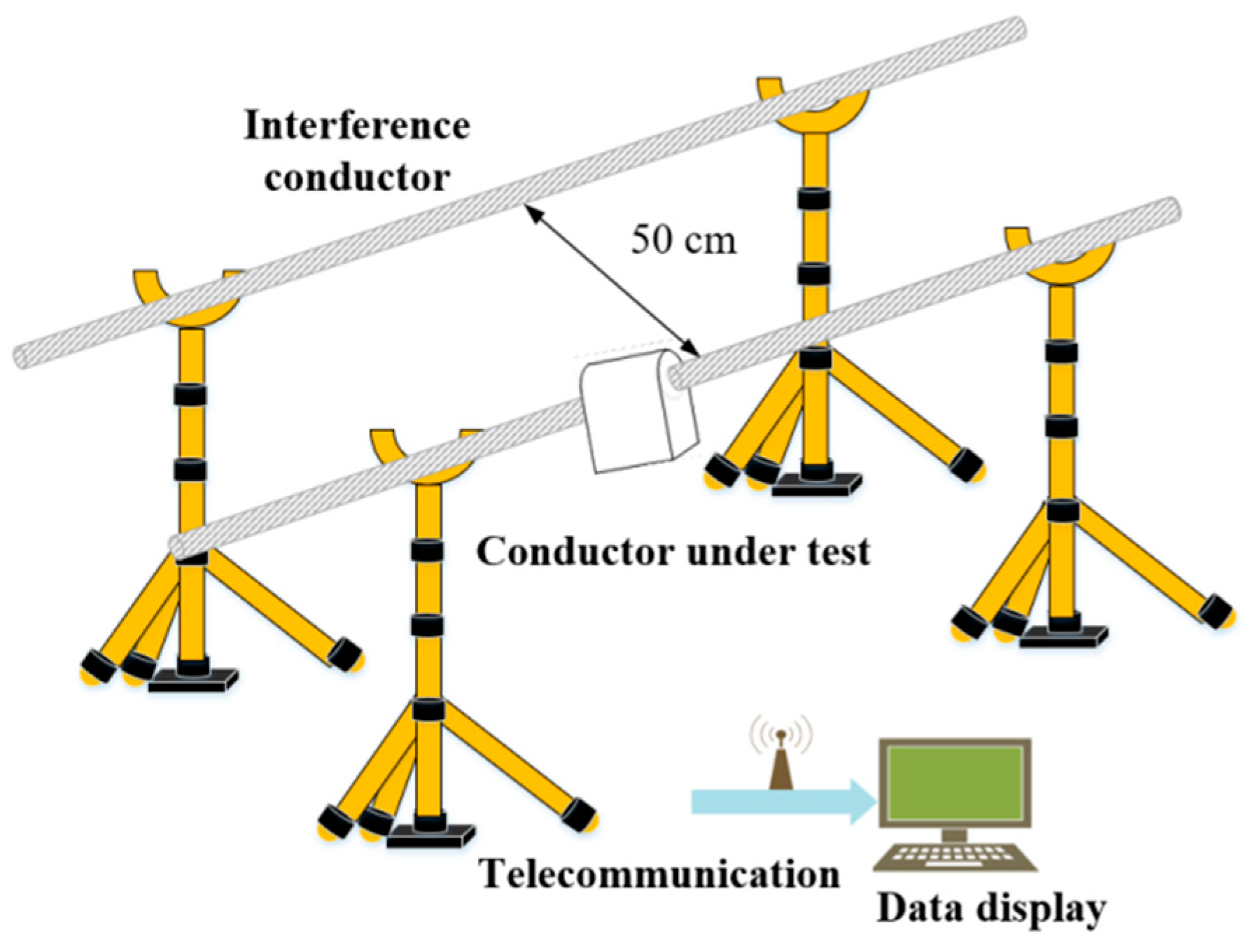
4.3. Anti-Interference Test
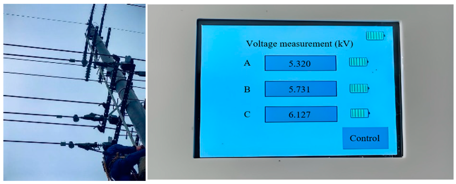
4.4. Field Application Test
5. Conclusions
- The maximum relative deviation of the developed measuring device is 1.215% in the voltage range from 4.61 kV to 6.92 kV, which can accurately measure the steady-state voltage.
- The output of the measuring device is stable at the zero position. In the case of alternating electric field coupling, the device can suppress the interference of the spatial electromagnetic field, with the maximum error increase of 1.313%, showing good shielding and anti-interference ability.
- In the practical application of the measuring device on a 10 kV line, the measurement floating error is much less than the voltage to be measured, being within the acceptable range of power detection operation, which verifies the effectiveness of the design architecture in this paper and lays a foundation for subsequent promotion and reference.
Author Contributions
Funding
Data Availability Statement
Conflicts of Interest
References
- Yang, Q.; Sun, S.; Sima, W.; He, Y.; Luo, M. Progress of Advanced Voltage/Current Sensing Techniques for Smart Grid. High Volt. Technol. 2019, 45, 349–367. [Google Scholar] [CrossRef]
- Chen, K.L.; Guo, Y.; Ma, X.Y. Contactless voltage sensor for overhead transmission lines. IET Gener. Transm. Distrib. 2018, 12, 957–966. [Google Scholar] [CrossRef]
- Bai, H.; Ouyang, J.; Pan, S.; Wu, L.; Yuan, Z. Measurement technology of Ground leakage resistance of Distribution Network based on zero sequence voltage regulation. J. Electr. Power Sci. Technol. 2022, 37, 126–132. [Google Scholar] [CrossRef]
- Feng, D.; Liu, H.; Li, J.; Bi, T. Non-contact Measurement Method of Transmission Line Voltage Based on Electric field Sensor Array. High Volt. Technol. 2024, 50, 292–301. [Google Scholar] [CrossRef]
- Han, Z.; Xue, F.; Yang, G.; Yu, Z.; Hu, J.; He, J. Micro-Cantilever Capacitive Sensor for High-Resolution Measurement of Electric Fields. IEEE Sens. J. 2021, 21, 4317–4324. [Google Scholar] [CrossRef]
- Huang, Z. Research on Transient Housing Voltage Measurement Method of Gas insulated Switchgear. Electrotech. Mater. 2023, 6, 60–62+66. [Google Scholar] [CrossRef]
- Ke, K.; Qing, Y.; Zhou, J.; Qiu, Z.; Yao, Z.; Chen, N. Piezoelectric PZT Film-Driven Resonant Torsional MEMS Electric Field Sensor. IEEE Sens. J. 2024, 24, 31921–31931. [Google Scholar] [CrossRef]
- Ke, K.; Yang, Q.; Qiu, Z.; Liao, W.; Zhou, J. Research review of non-contact voltage/electric field sensor. Hunan Electr. Power 2023, 43, 71–78. [Google Scholar]
- Qi, L.; Zhang, G.; Liu, J.; Qin, Z.; Song, Z.; Wang, J. Design and Optimization of Electromagnetic Pulse D-Dot Electric Field Sensor. High Vol. Apparatus. 2018, 54, 237–241+247. [Google Scholar]
- Rao, Y.; Wei, S.; Liu, Y.; Liu, J.; Li, H.; Liang, G.; Yang, Q.; Chen, N. Research on Sensing and Temperature Characteristics of Chip based Optical Silicon based Electric Field Sensor Based on Electro optic Polymer Thin Film. High Vol. Apparatus. 2024, 60, 65–71. [Google Scholar]
- Han, Z.; Hu, J.; Li, L.; He, J. Micro electric field sensor device for cantilever beam driven by electrostatic force. Engineering 2023, 24, 184–191. [Google Scholar] [CrossRef]
- Zhang, Y.; Ye, Y.; Li, H.; Xiong, S. Differential non-contact Voltage Measurement based on Harmonic Injection method. Sci. Technol. Eng. 2024, 24, 245–251. [Google Scholar]
- Zhang, Z.; Xia, S.; Peng, C.; Zheng, F.; Liu, J.; Liu, X.; Gao, Y.; Peng, S.; Xing, X. Method for Wide-frequency-range Field Detection by MEMS Electric Field Sensor. Instrum. Tech. Sens. 2023, 7, 1–7. [Google Scholar] [CrossRef]
- Lawrence, D.; Donnal, J.S.; Leeb, S.; He, Y. Non-Contact Measurement of Line Voltage. IEEE Sens. J. 2016, 16, 8990–8997. [Google Scholar] [CrossRef]
- Zhu, S.; Zeng, H.; Wang, S.; Fu, Z. Design of Novel Micromachined AC/DC Electric Field Sensor. Instrum. Tech. Sens. 2021, 6, 41–45. [Google Scholar] [CrossRef]
- Liang, T.; Xue, S.; Lei, C.; Wang, W.; Li, Z.; Shan, C. Design and Preparation of High Frequency MEMS Pressure Sensor. Instrum. Tech. Sens. 2021, 6, 6–10. [Google Scholar] [CrossRef]
- Feng, K.; Tong, J.; Wang, Y.; Fang, D.; Xia, S. Design and Fabrication of an Electric Field Microsensor Based on the Structure of Piezoelectric Cantilever Beams. Sci. Technol. Eng. 2015, 15, 90–94. [Google Scholar] [CrossRef]
- Lei, H.; Xia, S.; Chu, Z.; Ling, B.; Peng, C.; Zhang, Z.; Liu, J.; Zhang, W. An Electric Field Microsensor with Mutual Shielding Electrodes. Micromachines 2021, 12, 360. [Google Scholar] [CrossRef]
- Han, Z.; Xue, F.; Hu, J.; He, J. Trampoline-Shaped Micro Electric-Field Sensor for AC/DC High Electric Field Measurement. IEEE Trans. Ind. Electron. 2022, 69, 13791–13798. [Google Scholar] [CrossRef]
- Han, R. Research on a Battery-Less and Contact-Less Optic Overvoltage Sensor and Measurement System Based on Pockels Effect. Ph.D. Thesis, Chongqing University, Chongqing, China, 2017. [Google Scholar]
- Xing, Y.; Liu, J.; Li, F.; Zhang, G.; Li, J. Advanced Dual-Probes Noncontact Voltage Measurement Approach for AC/DC Power Transmission Wire Based on the Electric Field Radiation Principle. IEEE Trans. Instrum. Meas. 2023, 72, 1–11. [Google Scholar] [CrossRef]
- McKenzie, G.; Record, P. Non-contact Voltage Measurement Using Electronically Varying Capacitance. Electron. Lett. 2010, 46, 214–216. [Google Scholar] [CrossRef]
- Zhang, B.; Wang, J.; Xi, S. On-line Monitoring of Overvoltage in Power Distribution Network Based on the Capacitance Divider. Autom. Electr. Power Syst. 2007, 21, 1648–1656. [Google Scholar]
- Xiao, Q.; Liao, Z.; Liu, G.; Wang, J.; Yu, C. Vector Electric Field Sensor Integrated Energy Supply and Voltage Inversion Method for Transmission Lines. Electr. Eng. 2024, 25, 24–31. [Google Scholar]


| Electrode Slice | Square 1 | Square 2 | Square 3 | Square 4 | Square 5 | Round 1 | Round 2 | Round 3 | Round 4 | Round 5 | Arc 1 | Arc 2 | Arc 3 | Arc 4 | Arc 5 |
|---|---|---|---|---|---|---|---|---|---|---|---|---|---|---|---|
| Area/cm2 | 6 | 12 | 18 | 24 | 30 | π | 2.25π | 4π | 6.25π | 9π | 3π | 3π | 6π | 6π | 12π |
| Sensor output/V | 1.86 | 2.14 | 2.30 | 2.54 | 2.80 | 1.70 | 1.94 | 2.14 | 2.40 | 2.70 | 2.02 | 2.06 | 2.60 | 2.60 | 3.32 |
| Output per unit area/V·cm−2 | 0.31 | 0.178 | 0.128 | 0.106 | 0.093 | 0.541 | 0.274 | 0.17 | 0.122 | 0.095 | 0.214 | 0.219 | 0.138 | 0.138 | 0.088 |
| Test Potential | Standard Value | Output Value UX/Kv | Error Δ/% | |
|---|---|---|---|---|
| Oscilloscope Reading/V | Theoretical Truth Value UN/V | |||
| 4.61 kV gear | 12.456 | 4.609 | 4.592 | −0.369 |
| 12.459 | 4.610 | 4.592 | −0.390 | |
| 5.19 kV gear | 14.026 | 5.190 | 5.244 | 1.040 |
| 14.024 | 5.189 | 5.137 | −1.002 | |
| 5.77 kV gear | 15.589 | 5.769 | 5.796 | 0.468 |
| 15.589 | 5.768 | 5.820 | 0.870 | |
| 6.35 kV gear | 17.158 | 6.348 | 6.396 | 0.803 |
| 17.160 | 6.349 | 6.420 | 1.118 | |
| 6.92 kV gear | 18.674 | 6.909 | 6.975 | 0.955 |
| 18.680 | 6.912 | 6.996 | 1.215 | |
| Test Potential | Standard Value | Output Value UX with No Interference Wire/kV | Output Value UX with an Interference Wire/kV | Error δ/% | |
|---|---|---|---|---|---|
| Oscilloscope Reading/V | Theoretical True Value UN/V | ||||
| 1 kV | 2.705 | 1000.85 | 1.012 | 1.024 | 1.186 |
| 2 kV | 5.408 | 2000.96 | 1.980 | 2.006 | 1.313 |
| 3 kV | 8.112 | 3001.44 | 3.058 | 3.089 | 1.014 |
| 4 kV | 10.812 | 4000.44 | 4.073 | 4.125 | 1.277 |
| 5 kV | 13.515 | 5000.55 | 5.069 | 5.086 | 0.335 |
| 6 kV | 16.220 | 6001.4 | 6.120 | 6.107 | −0.212 |
| 7 kV | 18.924 | 7001.88 | 7.066 | 7.075 | 0.127 |
| 8 kV | 21.625 | 8001.25 | 8.120 | 8.121 | 0.012 |
| 9 kV | 24.326 | 9000.62 | 9.175 | 9.195 | 0.218 |
| 10 kV | 27.031 | 10,001.47 | 10.196 | 10.220 | 0.235 |
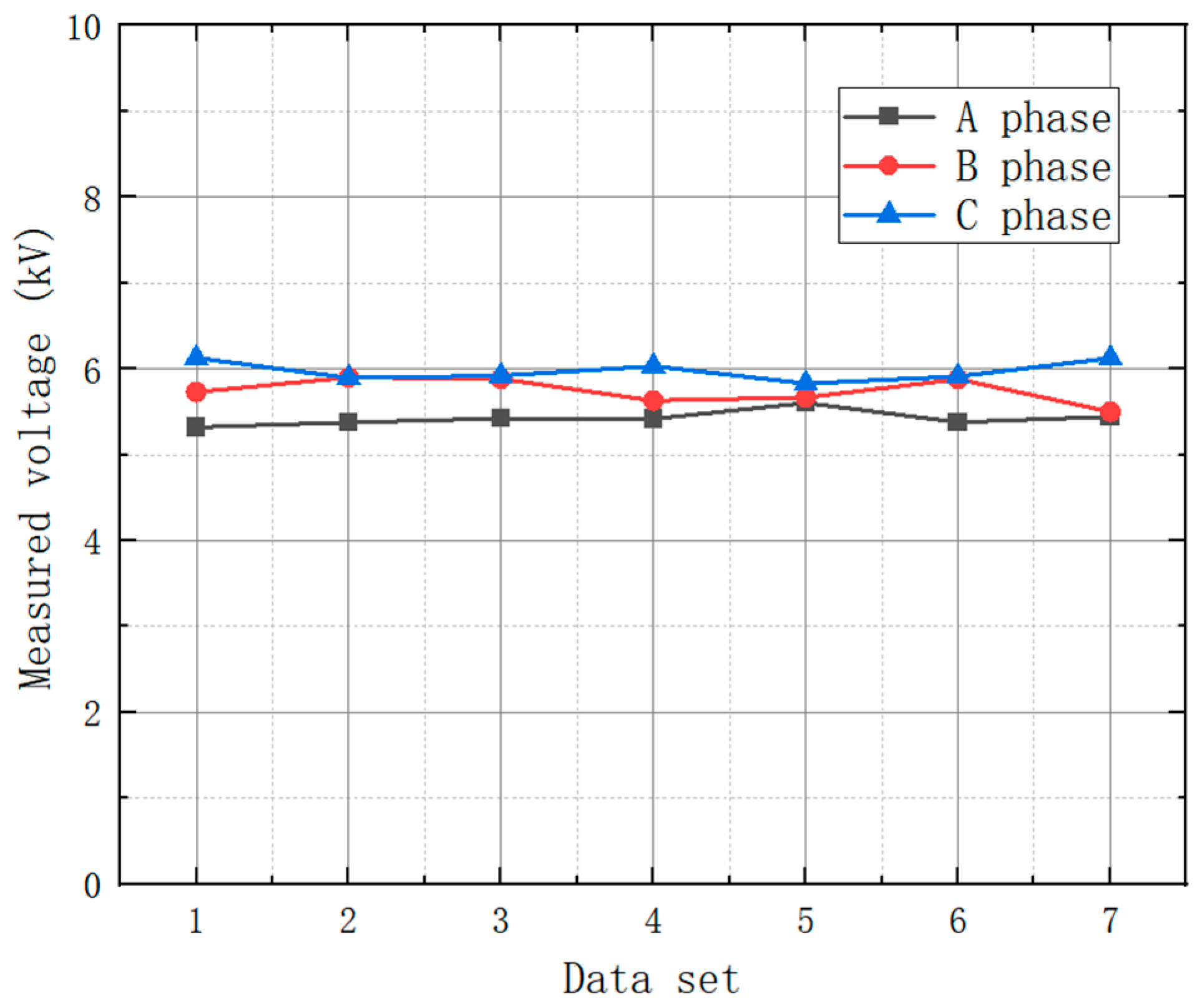
| To Test Phase | Voltage/kV | ||||||
|---|---|---|---|---|---|---|---|
| 1 | 2 | 3 | 4 | 5 | 6 | 7 | |
| A-phase | 5.320 | 5.375 | 5.421 | 5.420 | 5.604 | 5.358 | 5.441 |
| B-phase | 5.731 | 5.901 | 5.882 | 5.631 | 5.667 | 5.881 | 5.502 |
| C-phase | 6.127 | 5.895 | 5.921 | 6.031 | 5.830 | 5.911 | 6.122 |
Disclaimer/Publisher’s Note: The statements, opinions and data contained in all publications are solely those of the individual author(s) and contributor(s) and not of MDPI and/or the editor(s). MDPI and/or the editor(s) disclaim responsibility for any injury to people or property resulting from any ideas, methods, instructions or products referred to in the content. |
© 2025 by the authors. Licensee MDPI, Basel, Switzerland. This article is an open access article distributed under the terms and conditions of the Creative Commons Attribution (CC BY) license (https://creativecommons.org/licenses/by/4.0/).
Share and Cite
Zhu, X.; Zhang, Z.; Hu, C.; Wang, Z.; Liu, Z.; Yang, Q.; Zhou, J.; Qiu, Z.; Bao, S. Non-Invasive Voltage Measurement Device Based on MEMS Electric Field Sensor and Applications. Electronics 2025, 14, 2140. https://doi.org/10.3390/electronics14112140
Zhu X, Zhang Z, Hu C, Wang Z, Liu Z, Yang Q, Zhou J, Qiu Z, Bao S. Non-Invasive Voltage Measurement Device Based on MEMS Electric Field Sensor and Applications. Electronics. 2025; 14(11):2140. https://doi.org/10.3390/electronics14112140
Chicago/Turabian StyleZhu, Xueqiong, Ziyang Zhang, Chengbo Hu, Zhen Wang, Ziquan Liu, Qing Yang, Jianglin Zhou, Zhenhui Qiu, and Shijie Bao. 2025. "Non-Invasive Voltage Measurement Device Based on MEMS Electric Field Sensor and Applications" Electronics 14, no. 11: 2140. https://doi.org/10.3390/electronics14112140
APA StyleZhu, X., Zhang, Z., Hu, C., Wang, Z., Liu, Z., Yang, Q., Zhou, J., Qiu, Z., & Bao, S. (2025). Non-Invasive Voltage Measurement Device Based on MEMS Electric Field Sensor and Applications. Electronics, 14(11), 2140. https://doi.org/10.3390/electronics14112140