1. Introduction
Monitoring and tracking the movement of persons is an significant element in the field of security under certain legal and technical conditions. Currently, the issue is not only focused on monitoring and tracking the movement of persons and entities in the outdoor environment but also within confined spaces. Knowing the positions of persons moving in a space is essential, for example, in terms of surveillance of authorized or un-authorized movement of persons in a protected facility or in terms of the surveillance of per-sons in order to prevent the spread of infectious diseases. Similarly, knowing the movement of people and entities (e.g., goods) can significantly help to optimize processes in an organization.
Indoor positioning systems are a set of hardware and software solutions that are used to wirelessly locate the position of people or entities inside buildings [
1].
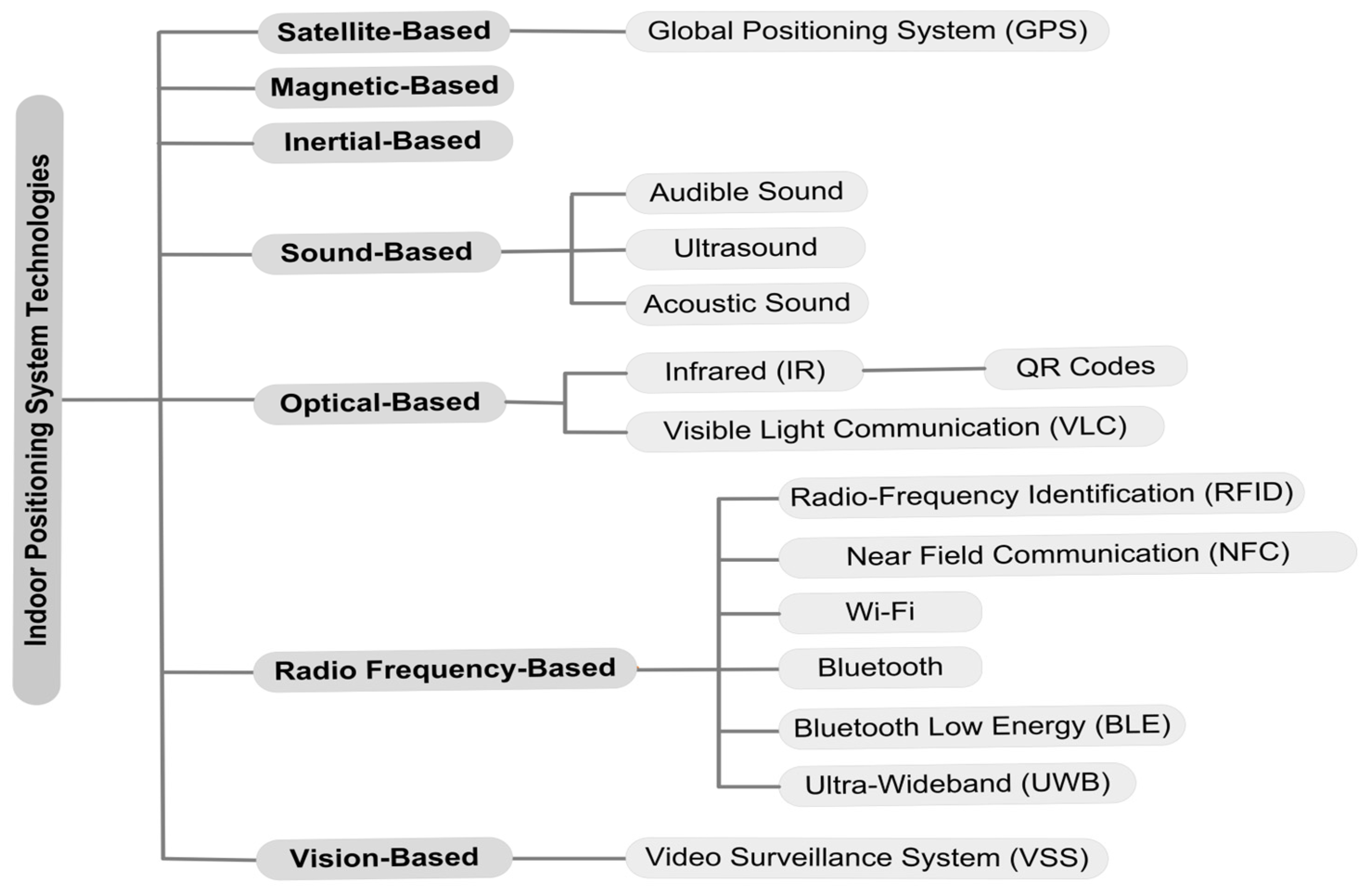
There are several types of technologies that can be implemented to monitor and track the location and movement of people and entities. Depending on the principle of operation, there are satellite, magnetic, inertial sensors, acoustic (audible sound, ultrasonic sound, acoustic sound), optical, radio frequency (Wi-Fi, Bluetooth Low Energy technology, radio frequency identification, and ultra-wideband) and visual sensors. The individual technologies for monitoring and tracking the movement of people and entities are illustrated in
Figure 1 [
2].
The best known Global Positioning System (GPS) is based on the principle of satellite technology. It provides accurate time and location at any time through a satellite navigation system [
4,
5,
6].
Systems using magnetic fields to determine the location and movement of people and entities in indoor environments are becoming popular. The magnetic field is present all around us and no additional power consumption is required. The magnetic field strength is stable within a confined space, and changes in strength are minute [
7,
8].
Inertial sensors are based on inertia. Inertial sensors include accelerometers and gyroscopes. They are independent of the environment, and as a result, external references and installation are not required [
9].
These technologies work on the principle of sound wave propagation. As sound waves propagate more slowly than electromagnetic waves, time synchronization is facilitated [
2,
3].
Optical signals are a form of electromagnetic radiation and their use within location systems is limited by visibility [
4].
Infrared technology is based on the use of electromagnetic radiation, with wavelengths longer than those of the visible light spectrum [
3]. The advantage of QR codes is the ability to detect them from longer distances compared to the detection range of RFID tags [
10,
11].
Visible light communication (VLC) is a technology that uses visible light modulation to facilitate high-speed Internet connectivity [
12,
13].
Radio Frequency Identification (RFID) is a contactless automated identification technology. It enables the target object to be recognized and relevant information and critical characteristics to be obtained through radio frequency signals [
14,
15].
Near-Field Communication (NFC) is a wireless communication standard that allows two devices within a short range to establish a communication channel over radio waves in a short period of time [
16,
17].
Wi-Fi is a set of standards allowing electrical devices to connect to a wireless local area network (WLAN) currently based on the IEEE 802.11 specification, thus enabling, for example, the Internet of Things (IoT) [
18].
Bluetooth is a standard wireless technology for short-range communication between fixed and mobile devices over short distances using short-wavelength radio waves in the 2400 to 2485 MHz radio bands [
19,
20].
Bluetooth Low Energy (BLE) is characterized by low acquisition cost, energy efficiency and ease of implementation. The technology aims to extend the lifetime of battery-powered devices by allowing short data transmissions instead of continuous data streams, which causes faster battery drainage [
21].
Bluetooth Low Energy, known as Bluetooth Smart, is a short-range wireless technology that is suitable for low-energy sensors powered by small coin cell batteries. Signal range can be affected by various environmental factors, which can lead to inaccurate results when calculating distance using the RSSI technique [
22,
23,
24]. The BLE data format contains four main types of information, namely UUID, Major, Minor and Tx-power [
25].
Ultra-wideband (UWB) technology is one of the short-range wireless technologies. A UWB signal contains different frequency components, which increases the probability of the signal passing through obstacles [
26,
27].
The purpose of a
Video Surveillance System (VSS) is to monitor activity in public or private scenes through cameras [
28]. It involves detecting and tracking objects, analyzing their movements and responding to objects [
29,
30].
Table 1 compares the different technologies in terms of usability in the environment, real-time localization, sensor range, traceability, and the ability to locate several persons and entities.
Magnetic, inertial, ultrasound or infrared technologies are used for the purpose of localization, especially in combination with other technologies. Most of the above-mentioned localization technologies are suitable for use in both outdoor and indoor environments. GPS technology is usable in outdoor environments that are covered by a signal. However, indoor use is limited due to the impermeability of signals through building structures. Ultrasound, RFID and NFC systems can be implemented mainly indoors. Technologies enabling the real-time tracking of objects and people include the GPS, IR, VLC, RFID, Wi-Fi, Bluetooth, BLE, UWB and a VSS. Some of the technologies have a limited range within which the transmitting and receiving devices are able to communicate with each other. Ultrasonic systems, IR, NFC or QR codes can be characterized as short-range technologies. The range of QR codes depends on the size of the code itself. The larger the QR code, the more the reading device is able to scan the code from a greater distance. RFID technology, like Wi-Fi and a VSS, allows devices to receive transmitted signals up to 50 m. At high frequencies, there is a higher propagation slope, which means that the signal degradation occurs faster with distance. This implies that technologies with a higher propagation slope may be more sensitive to obstacles and distance. Compared to Wi-Fi and VSS, the communication range of Bluetooth, UWB and BLE technology is lower. However, a communication range of approximately 20–40 m is sufficient for the needs of monitoring and tracking the movement of people and entities indoors. By tracking, we mean the ability of the technology to determine position in space. RFID, NFC, Wi-Fi and QR code technologies in terms of location only provide information about the presence or absence of an entity in a given space. Monitoring is possible based on information about the time of presence of an entity in a given space. However, it is not possible to determine the movement of the entity in the space. Locating multiple persons and entities is not possible with NFC technology and QR codes. It can be concluded that RFID, Wi-Fi, UWB and VSSs appear to be the most suitable in terms of technology range. However, in contrast to the outdoor environment, it is not important for indoor spaces to focus on the greatest possible range of the technology. For the design and implementation of a suitable indoor location system, the ability of the technology to determine the specific location of a person and entity in the space is the most significant characteristic. The disadvantage of implementing a VSS for monitoring and tracking the movement of persons is the need to ensure sufficient coverage of the space by the detection characteristics of the cameras at the reconnaissance stage, and the camera system would also need to have face recognition functionality or other identification feature necessary for monitoring and tracking the entity.
The Bluetooth Low Energy technology can be used both outdoors and indoors and enables the real-time location of people and entities. The communication distance for transmitting signals is 25 m, which is sufficient for indoor environments. This technology is capable of tracking persons and entities, i.e., providing information about the location and movement of persons and entities in a given space. In view of these facts, BLE is the most suitable for monitoring and tracking the movement of persons and entities in confined spaces.
These technologies are now widely used in the field of localization, depending on the environment in which they are implemented. GPS technology is the most widely used for localization in outdoor environments. It is used for the navigation of vehicles, in aviation, and also for navigation of individuals. Wi-Fi, UWB, VLC, RFID or BLE technologies are used for tracking the movement and location of people, the tracking of assets, goods and inventory in warehouses, and the tracking of medical equipment, and are part of smart buildings. Magnetic, IR, Ultrasound, Inertial or NFC technologies can also be used for location purposes, but usually in combination with another technology.
There are several localization techniques that are used to estimate the location of people and entities. The indoor positioning techniques are categorized based on the parameters, which are direction, signal and time. The direction-based techniques include Angle of Arrival (AoA). Signal-based techniques include a Received Signal Strength Indicator (RSSI), Channel State Information (CSI) and Reference Signal Received Power/Reference Signal Received Quality (RSRP/RSRQ). Time-based techniques are Time of Arrival (ToA), Time of Flight (ToF), Time Difference of Arrival (TDoA), Round Trip Time (RTT), Phase of Arrival (PoA) and Phase Difference of Arrival (PDoA) [
33,
34].
This paper interprets the results of the deployment and testing of an indoor positioning system based on Bluetooth Low Energy beacon technology in a real medical facility. The aim of the testing was to verify the functionality and reliability of the proposed prototype indoor positioning system in a confined space and, at the same time, to apply Fingerprinting as a method for determining the location of moving persons and entities. This paper describes the architecture of the indoor positioning system, where Bluetooth beacons are transmitters possessed by persons moving in space or attached to mobile medical equipment, and the receiving devices are microcomputers from the Raspberry Pi series. Data from the beacons, including RSSI values, are sent over the network infrastructure to a server and subsequently stored in a database. The results of the research include a concrete implementation of the system in a healthcare facility, including the deployment of the components forming the indoor positioning system. Subsequently, the Fingerprinting algorithm is applied to determine the most probable location based on Pearson’s correlation coefficient.
2. Materials and Methods
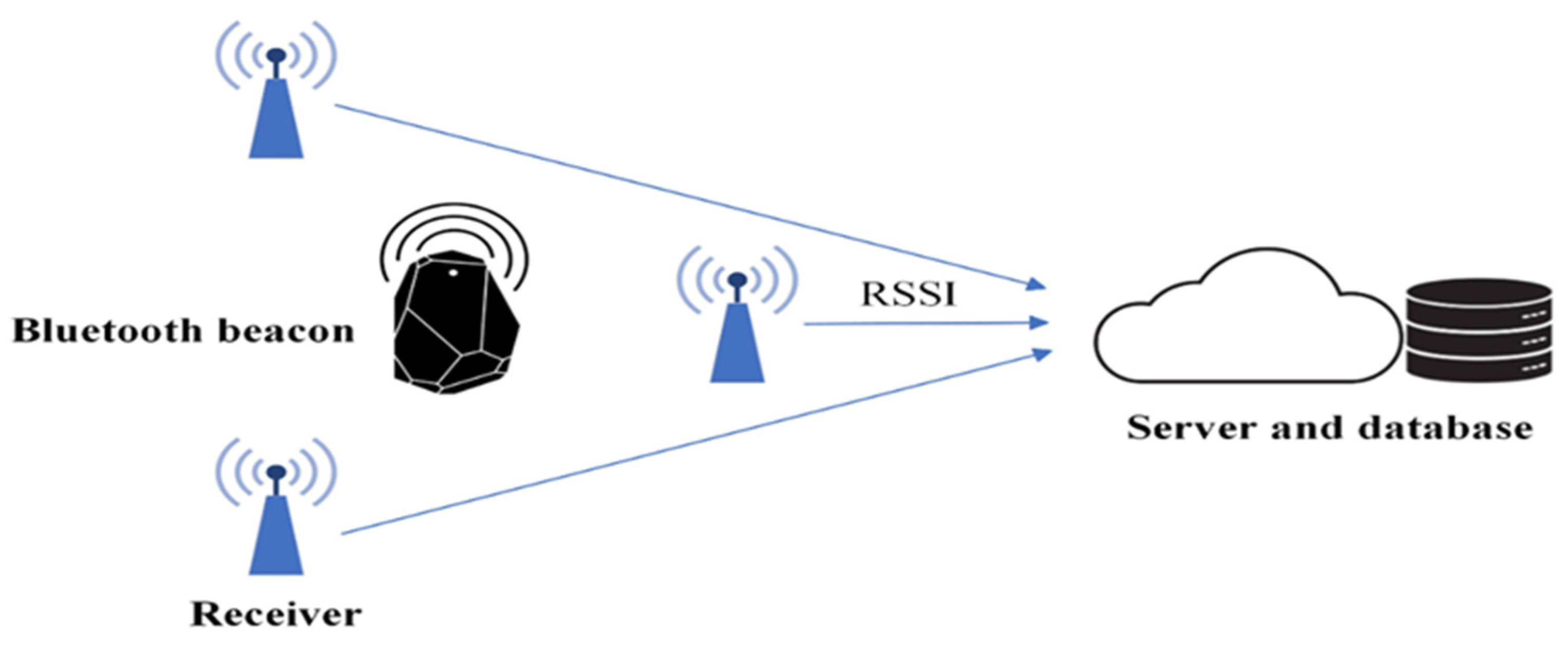
For the purpose of the installation, an indoor positioning system architecture was chosen in which the transmitting device is a Bluetooth Beacon operated by a person moving in the space, or the device is attached to a moving object, and several receiving devices are installed at fixed locations in the space. For the purpose of testing the system in a healthcare facility, the installation of the receiving devices on stands that were placed in the monitored space was chosen. The devices communicate with each other via Bluetooth Low Energy technology. The transmitting device continuously transmits radio signals, which are received by the receiving devices and subsequently sent to a server and stored in a database. The architecture of indoor positioning system is interpreted in the
Figure 2.
The transmitting devices are BLE beacons Gigaset G-Tag Red. The receiving devices are Raspberry Pi Zero microcomputers. The total number of transmitting devices is 25. The transmitting devices are operated by the staff of the healthcare facility, with 4 devices attached to mobile healthcare devices.
Raspberry Pi microcomputers, or an alternative using Arduino microcontrollers, can also be used for security purposes as access control systems in the event that tracking the movement of moving persons or entities would not be required, but information about which room they are present in would be sufficient [
44,
45].
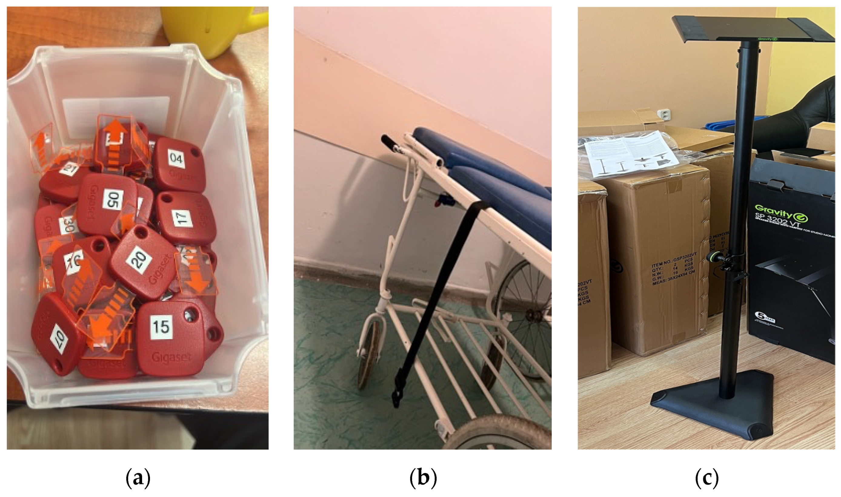
Individual transmitting devices could be attached to keys or to a lanyard that could be worn around the neck, for example. It was necessary for the staff of the healthcare facility to carry the BLE beacons with them at all times. For this reason, convenience had to be taken into account when wearing them on a daily basis. In addition to the actual wearing of the BLE beacons by the medical staff, several devices were attached to moving beds, as shown in
Figure 3.
As shown in
Figure 3, for the purpose of installing the receiving devices, racks were used to which the devices were attached in order to avoid interference with the building structures of the healthcare facility. The stands were chosen to make installation simple and safe. Due to the design of the racks, no additional structural modifications were necessary. The location of receiving devices in a health facility and their attaching to the rack is shown in
Figure 4.
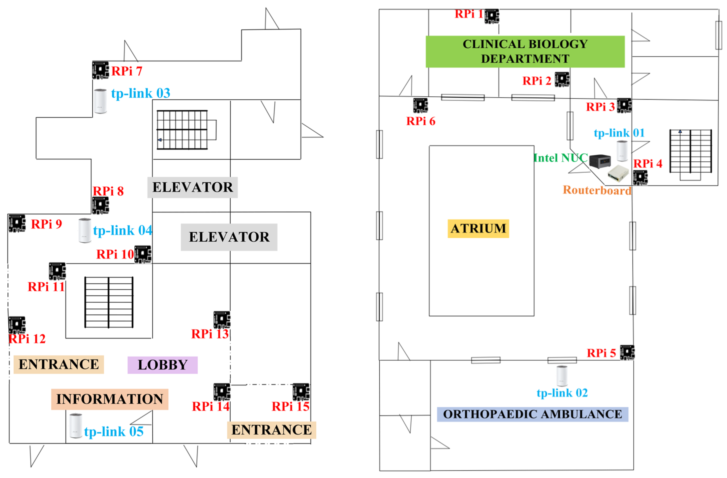
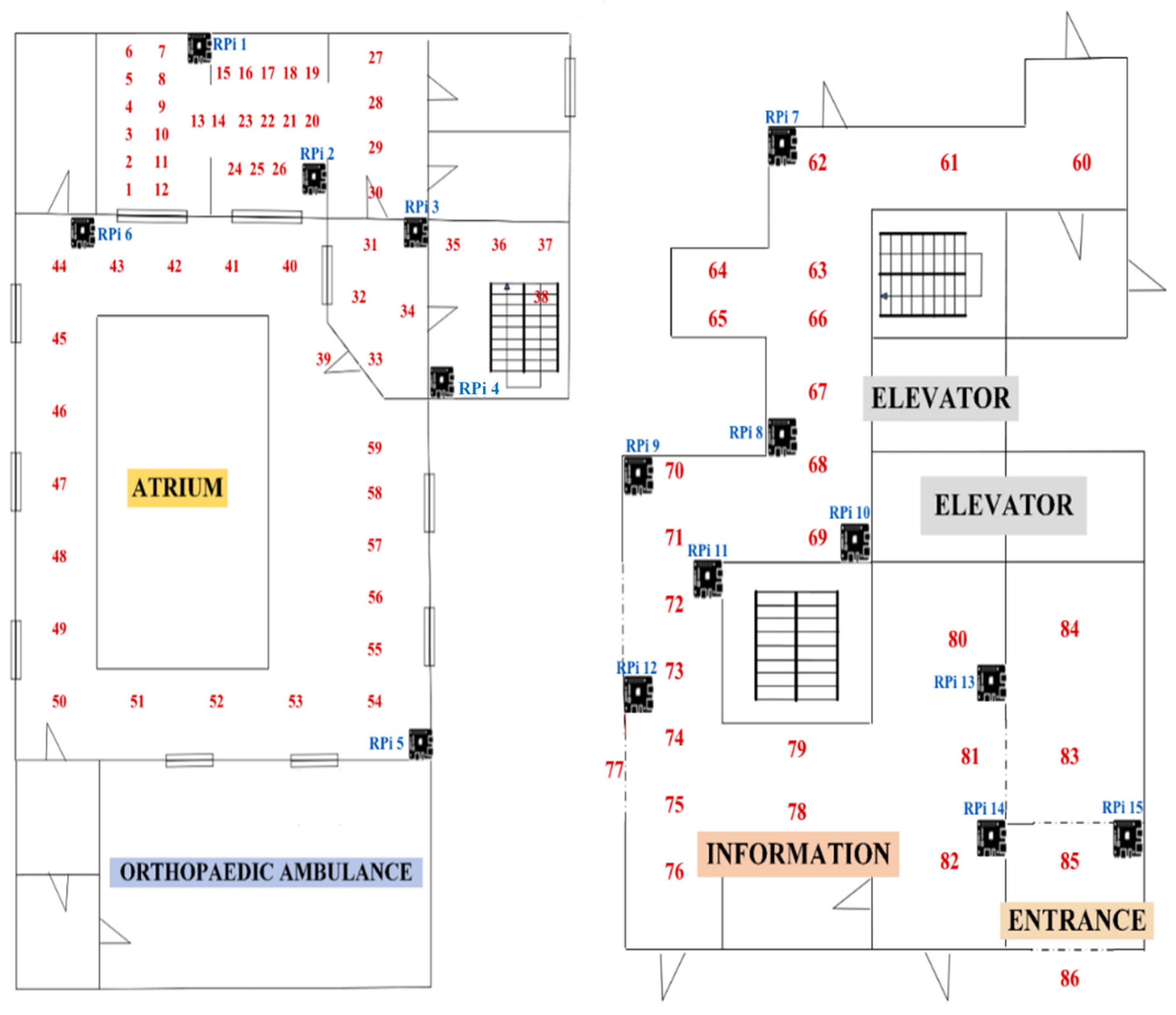
In total, 15 receiving devices were installed at a height of 1.6 m in the clinical biochemistry department, atrium and lobby of the health facility. When placing the racks, emphasis was placed on not restricting activities during the operation of the health facility, including the movement of patients, staff and healthcare mobile equipment. The device layout plan is shown in
Figure 5.
The diagrams above show the departments of the healthcare facility in which the indoor positioning system was tested. The designation RPi represents the individual receiving devices that were deployed in the departments. In the clinical biochemistry department, a server, a Mikrotik router connected via a SIM card to the Internet and the first TP-Link skeletal network router were deployed.
The power source of the receiving devices was an external 50,000 mAh Powerbank, which was able to operate continuously for 5–7 days.
In order to ensure that the relevant data of the transmitting devices were sent to the server, it was necessary to create a skeletal Wi-Fi network. The procedure for creating a Wi-Fi network consists of the following steps:
Wiring Routerboard MikroTik RB951Ui-2HnD;
Connecting the router to the Internet;
Connecting the Intel NUC miniserver via Ethernet to the MikroTik router (Ethernet port 2);
Connecting the TP-link Master Mesh marked 01 via Ethernet to the MikroTik router (Ethernet port 3);
Connecting TP-link Slave 02-05 in sequence.
As shown in
Figure 6, the MikroTik routerboard was connected to the Internet. A server was connected to the router via cabling, using Ethernet port 2, and a Master TP-link 01 was also connected to the router to create and manage the Mesh network. Subsequently, additional TP-link Slave routers labeled 02-05 were connected. Each additional connected router must be within the Wi-Fi range of the previous one. In this way, a skeleton Wi-Fi network was created, connected to the server and to the Internet.
Once the skeletal Wi-Fi network was established, the receiving devices were connected to external power devices and then attached to racks that were deployed in given sectors of the healthcare facility. Once started, each receiving device logged into the Mesh Wi-Fi network, locating a server in the network and establishing connectivity, automatically sending data about the transmitting devices in range to the server.
Subsequently, the system was calibrated. The monitored area was divided into squares of approximately 2 m × 2 m. The squares represent the calibration points and are therefore positions marked with a serial number from 1 to 86. The calibration points were located in each department of the health facility as follows:
The person in possession of the transmitting device stood in the center of each square—the calibration point—for 30 s. The individual calibration points were marked with a serial number. During the 30 s, the database was filled with RSSI values. The schematic of the calibration point layout is shown in
Figure 7.
Subsequently, it was necessary to create a mobile application for the purpose of calibration. Through the app, it was possible to record RSSI values for each position individually at the specified time intervals. In the application, it was possible to see how many RSSI values were received by each receiving device. A larger number of RSSI values received meant that the receiving devices were in range and closer. Devices that were not in range did not receive any RSSI values.
The mobile application created for calibration purposes has been adapted to receive data only about registered devices. Other devices beyond the proposed system operating on the Bluetooth Low Energy basis were filtered out at the beginning so as not to overload the database. System calibration via mobile app is shown in
Figure 8.
If the number of RSSI values received was lower, it means that the receiving device is in range but is remote from the transmitting device. The calibration of individual positions using the Fingerprinting method is one of the more challenging activities in terms of duration.
The Fingerprinting method is characterized by high indoor positioning accuracy. The advantage is that the algorithm is resistant to multipath effects and the measurement does not require the direct visibility of access points. Fingerprinting-based localization consists of an offline phase, also called the training phase, and an online phase, which is called the testing phase. In the offline phase, the location is explored to collect RSSI vectors of all the recorded signals from different access points at many reference points of known locations. Within this phase, a database is created where the site survey data are collected and processed. In the online phase, mobile devices record the data in real time. The data are then tested using the database. The output of the test is used to estimate the location of the mobile device in such a way that each training point is searched for the location that most closely matches the location of the target [
46,
47,
48,
49].
The calibration of the 86 calibration points took 1 h, 24 min and 27 s. At each calibration point, the person with the transmitting device remained between 30 and 45 s. The use of a mobile app greatly simplified and streamlined the calibration process. Therefore, it will be essential in the actual deployment of the system.
The creation of a database of RSSI values is necessary because of the application of the Fingerprinting positioning algorithm. The algorithm consists of comparing the RSSI values in the database with the RSSI values recorded in real time. The actual comparison of RSSI values is performed by means of Pearson’s correlation coefficient (PCC), which determines the probability with which a person is located at a given position in space. The dependence rate by correlation coefficient is shown in
Table 2. For the calculation of the Pearson’s correlation coefficient, there is the formula below:
The RSSI values for each receiving device in range were obtained by calibration. Subsequently, the data in the database were adjusted so that all receiving devices in range with their corresponding RSSI values were assigned to each position. As mentioned, at each position, the person stayed for more than 30 s, and therefore, multiple RSSI values were obtained for each receiving device. The resulting calibration matrix included the arithmetic mean RSSI for the combination of the position and receiving device.
In
Table 3, the arithmetic means of the selected calibration points are interpreted. As can be seen from the table, calibration points 1, 2 and 3 have a range to receiving devices 1–6. Calibration points 73 and 83 are located at the opposite end of the building and have a range to receiving devices 9–15, which were located closer to the given calibration points.
If the error margin is large, it can affect the calibration process and the overall positioning accuracy through the application of the Fingerprinting algorithm. There were 2 conditions within the implemented calculations, namely the data collection interval, which was 30 s, and the number of RSSI values for a given time interval, namely 100 RSSI values. The calibration process was completed when either the time interval of 30 s or 100 RSSI values were reached. The greater the number of RSSI values, the more accurate the arithmetic mean calculations.
3. Results
After the system was configured and the calibration matrix was created, the actual testing of the system in the conditions of the healthcare facility was carried out. The aim of the testing was to locate the position of the beacon in real time.
After the calibration matrix was configured, the transitions were performed once more after each calibration point. At each position, the RSSI values obtained were submitted to an algorithm to calculate the Pearson correlation coefficient.
As shown in the diagram in
Figure 9, the RSSI values from each receiving device are obtained first. This field of numbers was compared with the RSSI fields of all positions recorded in the calibration matrix. In this way, the Pearson correlation coefficient for each position in the calibration matrix was obtained. The one that is closest to a value of +1 is most likely the position that is currently occupied by the transmitting device possessed by the person moving around the object or the device attached to the mobile object. The following graphs show the correlation coefficients for each of the selected positions.
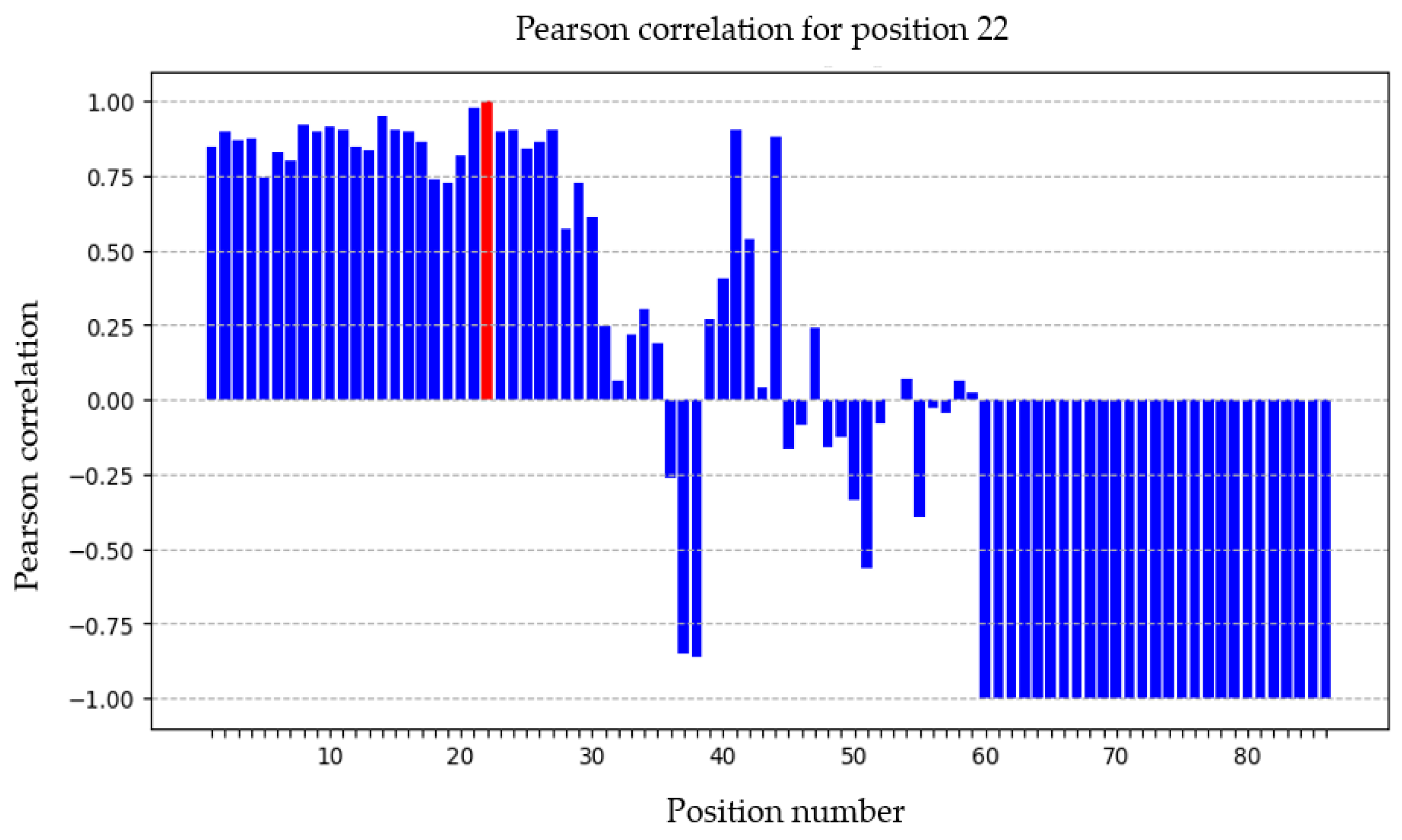
Position 22 was located in the clinical biochemistry laboratory. This area had the highest density of calibration points. In
Figure 10, the calibration point belonging to position 22 is marked in red. The red colour interprets that the transmitting device is most likely to be at a particular point according to the PCC, and thus the PCC value is closest to +1. The blue colour means that the other PCCs have lower values. Here, it can be seen that the correlation value is closest to +1; therefore, the transmitting device is most likely located at this position, which is also true in the real environment. The calibration points that are physically close to the measured position also have a correlation value close to +1. However, as the transmitting device moves further away from the measured position, the correlation value decreases until, in some cases, it reaches negative values. But the calibration points from 60 to 86 have a correlation value of −1. This is due to the fact that the recorded RSSI values of a particular transmitting device were not received by any receiving device or only by devices less than two in number.
For the analysis at each point, a minimum of 10 RSSI values received by devices that were within range were compared to the calibration matrix. In the case that less than three receiving devices were in range, or no devices were in range, the correlation values were not statistically significant.
In
Figure 11, position number 51 is shown. This position was in the atrium. As can be seen, the graph shows with high probability the particular point where the transmitting device was located at the time measured. All correlations of the calibration points that were located in the clinical biochemistry laboratory reached negative values. This implies that the receiving devices closest to these points received sufficient signals, but the distance from the desired position is large. Calibration points from 60 upwards achieved a correlation value of −1, indicating that the receiving devices did not receive sufficient data to calculate the correlation.
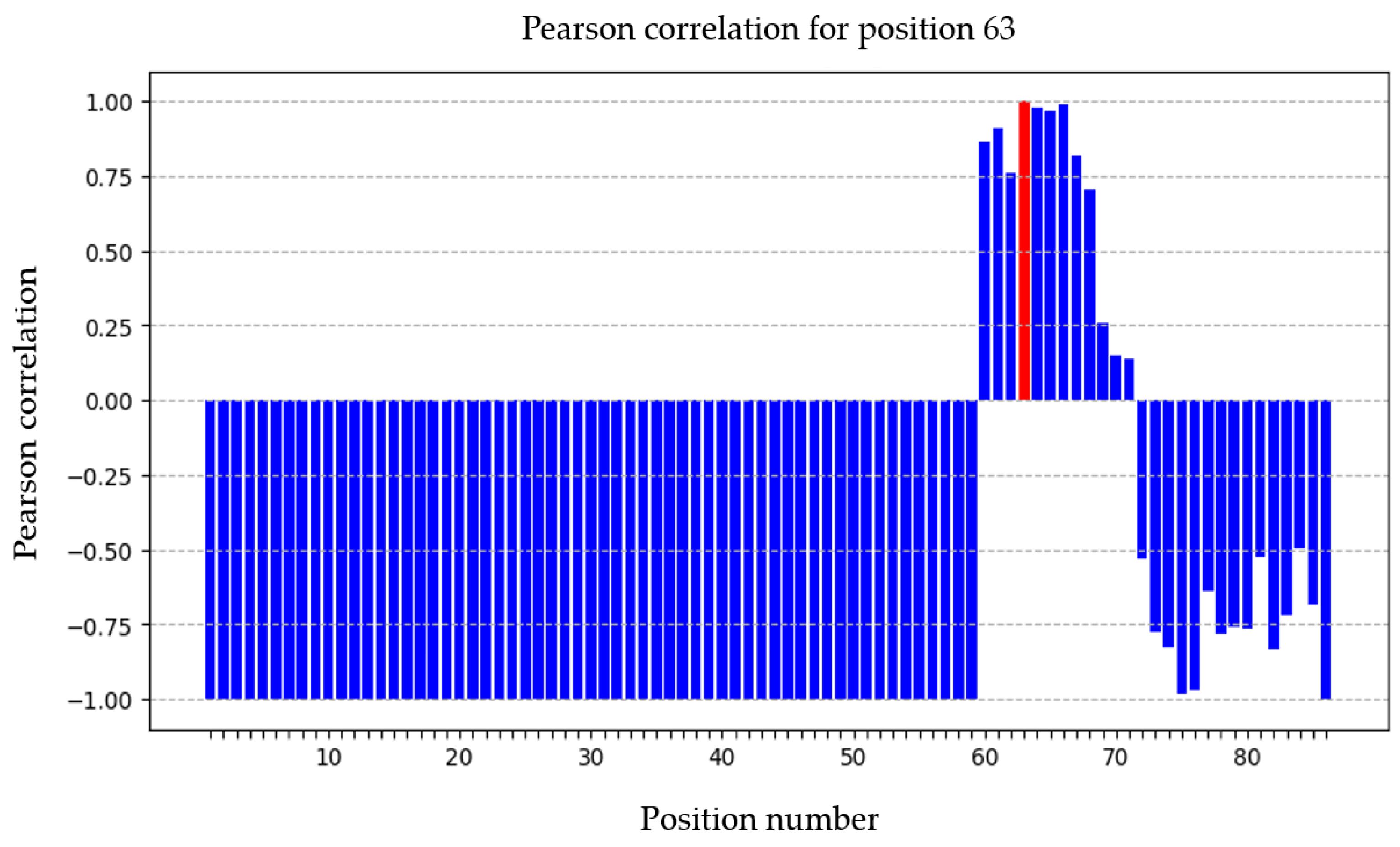
In the
Figure 12 is interpreted PCC for position 63, which was located in the corridor between the atrium and the entrance hall. The distance from the calibration points corresponding to the positions of the clinical biochemistry laboratory and the atrium was sufficient. The correlation value in these cases is equal to −1. However, on the other hand, the transmitting device was moved to the positions of the calibration points of the entrance hall. Based on the results obtained, it can be concluded that the correlation values at positions 72–86 are not equal to −1 but are still negative. This means that the receiving devices receive a sufficient number of RSSI values to calculate the correlation, but the measured position is remote.
Position 79 was located in the lobby.
Figure 13 shows the area in which the monitoring point is located. Positions from 1 to 59 had Pearson correlation coefficient values equal to −1. Positions from 60 to 71 were no longer equal to −1 but were still negative due to their distance.
The last one selected is position 86 shown in
Figure 14. This position was located in close proximity behind the entrance door to the lobby. This means that the transmitting device was located outside the premises but in close proximity to it. Also, in this case, the measured results and calculations show to which positions the transmitting device was closest and to which positions it was furthest away. As can be seen from the above, it is possible to determine with a high level of accuracy where a particular transmitting device was located at a particular time. However, it is necessary to position the receiving equipment so that there are at least three receiving devices within the range of each position. This is necessary in order to be able to calculate the Pearson correlation coefficient, where at least three values are needed for a linear dependence.
For better visualization, the Pearson correlation coefficient values for neighbor points are presented in
Table 4 in order to better evaluate the positioning accuracy and provide a reference for dynamic positioning analysis.
4. Discussion
The experimental testing of the indoor positioning system was carried out in a healthcare facility to determine the location of the beacon based on the Fingerprinting method. Good results were obtained in the testing carried out. The analysis included the calculation of the Pearson correlation coefficient, which allowed us to compare the measured values with a predefined calibration matrix and to identify the most probable position of the entity. The results of the testing indicated that the Fingerprinting method, although challenging for initial calibration and installation, can provide high accuracy approximately 2 m in positioning. The correlation plots showed that closer positions tend to have higher correlation values, while more distant positions have lower or even negative correlation values, illustrating the effectiveness of the method in different areas of the test environment. The difficulty and tediousness of system calibration can be corrected by using supporting applications such as a mobile app to perform the calibration. Such a tool will greatly facilitate and speed up the entire installation and then the subsequent adaptations to changes in the environment.
The proposed indoor positioning system is not only energy-efficient but also has low hardware costs, making it an affordable solution. By optimizing the use of available technologies, it minimizes the requirement for specialized devices, thus reducing not only procurement costs but also operating and maintenance costs. Its cost-effectiveness makes it suitable for a wide range of applications, from industrial applications to smaller businesses that need an accurate and reliable solution without a significant financial burden.
Solutions based on a system architecture where the transmitting devices are Bluetooth beacons typically installed on building structures and the receiving devices are smart devices such as watches or smartphones present a barrier in some types of operations. For example, in industrial facilities and factory production lines, it is essential to follow strict safety measures and ensure the continuity of work processes. Carrying and using smartphones in such work environments is inappropriate and often prohibited, given that their use can lead to the loss of concentration, increased risk of workplace accidents and disruption of production operations. It is therefore necessary to find an alternative solution suitable also for these types of operations, while the proposed system fulfills the requirements for implementation in industrial facilities and in areas where the use of smart devices is regulated. Among other things, there is a higher procurement cost in case it would be necessary to procure smart devices such as watches for each employee individually, since the price of a watch is approximately EUR 400–600, while the purchase price of Bluetooth beacons is in the range of EUR 10–30. The use of smartphones as receiving devices would seem to be one of the affordable solutions as smartphones are available to the majority of the population; however, this solution is not implementable for every type of operation as mentioned above.
The energy efficiency of the proposed indoor positioning system is based on the fact that the coin cell battery in the Bluetooth beacon has a battery duration of approximately 6 months, whereas a smartphone or smartwatch needs to be recharged approximately every 2–3 days, thus incurring electricity costs. There is also significant energy-saving potential in powering the Raspberry Pi Zero microcomputer, where a low voltage is required, or they can be powered by external 50,000 mAh batteries, as interpreted in our research results, with the said external battery being able to operate continuously for 7 days.
5. Conclusions
Within the framework of this research, the author’s team focused on the analysis and development of an autonomous information system designed for monitoring the movement and location of people and entities. This system is based on the BLE beacon technology, which enables the efficient tracking of moving entities in confined spaces. The aim of the study was to show the possibility of an innovative solution for the indoor positioning system, and the novelty of the constructed positioning system lies in the way of using components where Bluetooth beacons served as transmitting devices and Raspberry Pi Zero 2W microcomputers were the receiving devices. In this paper, the results of the experimental testing in a healthcare facility environment were interpreted. The actual testing presented in this paper was preceded by a series of laboratory tests of the system and the determination of the main method for positioning. The proposed system itself and its implementation in a healthcare facility can be a useful tool for improving the patient safety, optimization and efficiency of the entire healthcare processes.
The experimental testing shows that the use of Fingerprinting provides accurate and reliable results, even in heterogeneous healthcare environments. This method is compared to approaches that attempt to assign a specific distance to the RSSI value. These distance values can be used to determine the location of a particular BLE beacon using, for example, trilateration. In the case of detecting distances from a single receiving device, the data obtained were highly inaccurate. The RSSI tends to fluctuate due to external factors such as diffraction, absorption or interference that affect the radio waves. When using multiple receiving devices and comparing the signal ratios of the opposing devices, the results were significantly better. The measurements produced a deviation of approximately 66 cm, which is acceptable for larger areas where high accuracy is not required. A mean deviation of 66 cm was determined in the partial testing of the system aimed at determining the position of an entity using different approaches [
50]. The arithmetic mean of all measured deviations between the actual and the measured value was used to calculate the mean deviation. The main disadvantage was in the placement of the receiving devices. They would always have to be placed in pairs opposite each other. This would cause several problems in finding the correct placement in the space in real conditions.
In structurally complex environments, it can be challenging to guarantee 2 m positioning accuracy due to the absorption, diffraction or interference of signals due to the presence of obstacles or other interfering elements that can affect signal strength and stability.
From the above, the Fingerprinting method together with Raspberry Pi Zero microcomputers showed high potential in localization in confined spaces where traditional GPSs encounter technical limitations. The evaluation consisted of mapping the signal strength in different parts of the space beforehand and comparing these data with the actual signal, which proved to be highly accurate and reliable in localization. Receiving devices in this method can be placed more freely in space. The only significant factor is that at each calibration point, the range of the signal transmitted by the BLE beacon to at least three receiving devices must be within the range of the BLE beacon. This is due to the use of Pearson’s correlation coefficient, where for a calculation it is necessary to have at least three RSSI values from the calibration matrix and three corresponding RSSI values obtained in real time. The more receiving devices are in range, the more accurate the position localization of the BLE beacon will be.
Compared to current solutions, the results show that autonomous information systems based on BLE beacon technology can provide higher accuracy and reduce energy consumption. Another important finding is the verification of the theoretical assumptions about the impact of physical obstacles and spatial distribution on the localization accuracy. Although advanced localization technologies and methods are available, environments with complex topologies and various obstacles still pose a challenge to the accuracy of localizing people and entities. It was the Fingerprinting method that had the best results in terms of accuracy in a structured environment. However, there is a need for a further investigation into the optimization of the system for specific application conditions.


