Article

Low-Profile Omnidirectional and Wide-Angle Beam Scanning Antenna Array Based on Epsilon-Near-Zero and Fabry–Perot Co-Resonance

1
The School of Electronic Engineering, Naval University of Engineering, Wuhan 430033, China
2
School of Electronic Science and Engineering, Nanjing University, Nanjing 210093, China
*
Authors to whom correspondence should be addressed.
These authors contributed equally to this work.
Electronics 2025, 14(10), 2012; https://doi.org/10.3390/electronics14102012
Submission received: 3 May 2025 / Revised: 13 May 2025 / Accepted: 14 May 2025 / Published: 15 May 2025
(This article belongs to the Section Microwave and Wireless Communications)

Abstract

:
To address the inherent contradiction between low-profile design and high gain in traditional omnidirectional antennas, as well as the narrow bandwidth constraints of ENZ antennas, this study presents a dual-mode ENZ-FP collaborative resonant antenna array design utilizing a substrate-integrated waveguide (SIW). Through systematic analysis of ENZ media’s quasi-static field distribution, we innovatively integrated it with Fabry–Perot (F–P) resonance, achieving unprecedented dual-band omnidirectional radiation at 5.18 GHz and 5.72 GHz within a single ENZ antenna configuration for the first time. The directivity of both frequencies reached 12.0 dBi, with a remarkably low profile of only 0.018λ. We then extended this design to an ENZ-FP dual-mode beam-scanning array. By incorporating phase control technology, we achieved wide-angle scanning despite low-profile constraints. The measured 3 dB beam coverage angles at the dual frequencies were ±63° and ±65°, respectively. Moreover, by loading the impedance matching network, the −10 dB impedance bandwidth of the antenna array was further extended to 2.4% and 2.7%, respectively, thus overcoming the narrowband limitations of the ENZ antenna and enhancing practical applicability. The antennas were manufactured using PCB (Printed Circuit Board) technology, offering high integration and cost efficiency. This provides a new paradigm for UAV (Unmanned Aerial Vehicle) communication and radar detection systems featuring multi-band operation, a low-profile design, and flexible beam control capabilities.

1. Introduction

As wireless communication technologies advance rapidly, high-performance integrated antennas face growing demand. Omnidirectional antennas are widely used in mobile communications, wireless local area networks, and other scenarios due to their uniform radiation characteristics [1,2]. However, traditional omnidirectional antennas often encounter inherent trade-offs among operating frequency, geometric structure, and performance [3,4]. Particularly when pursuing a low-profile architecture, although some metasurface antennas can achieve subwavelength thickness, they usually have low gain or a complex structure [5,6,7]. Among emerging solutions, epsilon-near-zero (ENZ) metamaterial attracts attention for its unique electromagnetic response [8,9,10]. Based on the quasi-static field distribution characteristics of ENZ media, antennas can decouple the geometric structure from operating frequency, providing new insights for miniaturization and integration [11,12,13,14]. Furthermore, ENZ antennas can generate uniform in-phase electromagnetic wave at the radiation aperture, enhancing gain significantly [15,16,17].
However, limited by the inherent electromagnetic resonance characteristics of ENZ media, their performance is typically restricted to single-frequency narrowband optimization, and multi-frequency applications remain to be explored [18,19,20]. Meanwhile, Fabry–Perot (F–P) resonant cavity antennas, despite achieving high-aperture-efficiency in-phase radiation, face constraints of high profile and narrow bandwidth [21,22,23]. The question of how to integrate F−P resonance with ENZ antennas to collaboratively address the challenges of low profile, high gain, and multi-frequency compatibility still lacks a systematic solution. Additionally, there is no developed methodology for designing omnidirectional radiation antennas based on F–P resonance [24,25,26]. Furthermore, achieving wide-angle beam scanning under low-profile constraints remains a formidable technical challenge, particularly in applications such as UAV communications and radar detection [27,28,29,30].
In this paper, we implement ENZ media through a substrate-integrated waveguide (SIW) and propose a four-element high-gain omnidirectional ENZ-FP antenna array by leveraging its spatiotemporal decoupling characteristic. By combining the ENZ waveguide with the F–P resonance principle, we realized high-aperture-efficiency omnidirectional radiation at dual frequencies (5.18 GHz and 5.72 GHz), with directivity both reaching 12 dBi and peak gains of 9.8 dBi and 10.1 dBi, respectively, significantly improving spectral utilization efficiency. And the antenna profile thickness is only 0.018λ (λ is the wavelength in free space at the ENZ frequency), breaking the profile limitation of F–P resonant antennas [21]. Through structural optimization, we further developed a four-element phased antenna array that enables ±63° beam scanning at 5.14 GHz and ±65° at 6.0 GHz, which enables wide-angle beam scanning while maintaining large elevation angle coverage. Building upon this foundation, by integrating impedance matching networks, the −10 dB bandwidth of the two antennas were extended to 2.4% and 2.7%, respectively, addressing the narrowband limitation for practical applications. The designed antennas were fabricated using PCB technology, offering advantages such as low cost and ease of conformal integration, which provides a new paradigm for the application of ENZ media in wireless communications, radar detection, or related fields.

2. Omnidirectional Antenna Array

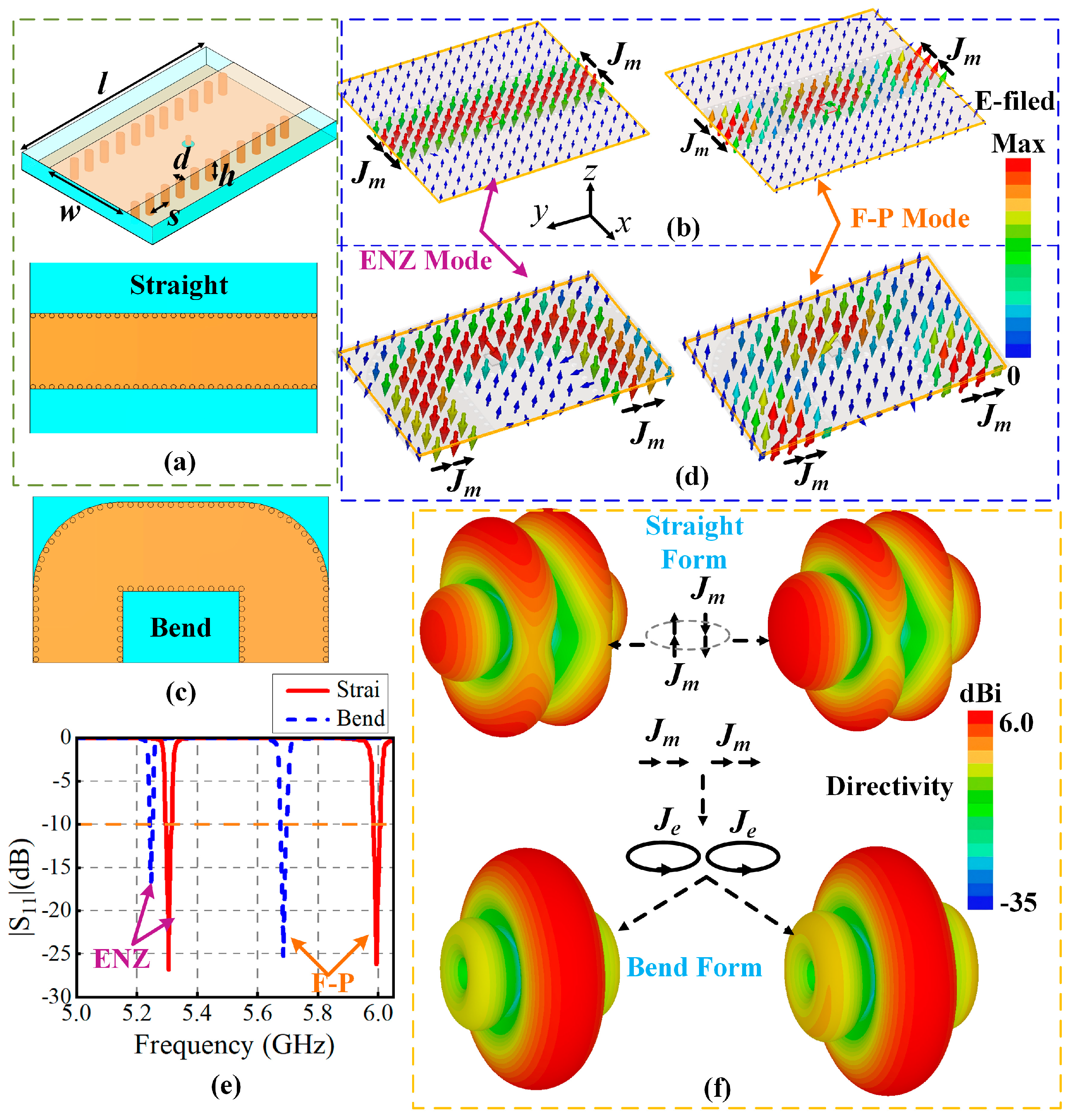
2.1. Theoretical Analysis

Figure 1a illustrates the perspective and top view of the straight SIW, where the dimensions of w, d, s, and h are 20 mm, 1.3 mm, 2.4 mm, and 0.508 mm, respectively, using the Rogers RT5880 dielectric substrate (εr = 2.2, loss tangent = 0.0009). According to [31], this structure can be equivalent to a rectangular waveguide with effective width weff and effective length leff, which are calculated as follows:
w e f f = w 1.08 × d 2 s + 0.1 × d 2 w
l e f f = l 1.08 × d 2 s + 0.1 × d 2 l
In the TE10 mode, the effective permittivity εeff of the waveguide can be characterized by the Drude dispersion model [32], expressed as follows:
ε e f f ( f ) = ε r c 2 / ( 4 w e f f 2 f 2 )
where c is the speed of light, f is the operating frequency of the SIW, and εr is the relative permittivity of the substrate. When εeff = 0, the SIW operates in the ENZ mode, exhibiting a near-zero propagation constant and an infinite wavelength. Its operating frequency f can be calculated as the cutoff frequency.
f p = c / ( 2 ε r w e f f )
Figure 1b, on the left side, shows the electric field distribution in ENZ mode when SIW is excited by a coaxial probe. Due to the infinite wavelength in the ENZ medium, the internal electric field is uniformly distributed with negligible phase variation, enabling in-phase radiation at the aperture. By combining the ground mirror effect and Huygens’ principle [33], an equivalent magnetic current source is formed at the aperture, expressed as JM = −2 n ^   × Ea, where n ^ is the normal vector and Ea is the tangential electric field at the aperture. However, unlike the conventional feeding way, when we only insert the feeding probe shallowly into the substrate, not only can the ENZ mode be excited normally, but the SIW shows an F–P resonance mode at a higher frequency, as shown on the right side of Figure 1b. In the F–P mode, the internal electric field exhibits transverse resonance with symmetric distribution around the center. A half-wavelength standing wave is formed along the waveguide channel, where a 180° phase shift occurs between the central feed and the radiation aperture. Through multiple reflections and phase superposition, in-phase radiation is achieved. The expression for the equivalent magnetic current source remains consistent with the ENZ mode, with similar radiation patterns. In this case, the SIW height h can be much smaller than the wavelength without affecting the ENZ resonance, thereby avoiding vertical electric field resonance. The resonant frequency of the F–P mode is derived as follows:
f F P = ( c / 2 ε r w e f f ) 2 + ( c / ε r l e f f ) 2
Figure 1f shows the far-field radiation patterns of the straight SIW under ENZ and F–P modes. Although the azimuthal radiation pattern of the magnetic current source resembles that of a current loop, the reverse of the phase between the two ends leads to pattern cancelation, failing to meet the omnidirectional radiation requirement. To address this, the SIW shape is optimized to achieve in-phase magnetic current source distribution. However, in conventional antennas, the geometric structure, electric field distribution, operating frequency, and radiation patterns are mutually constrained, making independent control challenging. In contrast, antennas designed with ENZ media enable decoupling between geometric shape and operating frequency. The resonant frequency of the ENZ mode is solely determined by the effective width and permittivity, according to Equation (4), with the electric field maintaining a quasi-static distribution. For the F–P mode, the resonant frequency is additionally influenced by the electric field propagation length according to Equation (5), while the electric field still retains the half-wavelength standing wave characteristic. Based on this, when modifying the SIW structure, the F–P resonant frequency can be adjusted by varying the propagation path length leff while keeping the ENZ frequency unchanged.
By bending the straight SIW (Figure 1c), the electric field distributions of the ENZ and F−P modes under excitation are shown in Figure 1d. Both modes generate equal-amplitude in-phase magnetic current sources at the radiation apertures, which can be equivalently modeled as parallel, electrically small loops. This enables high-gain omnidirectional radiation in the azimuthal plane (Figure 1f), breaking the limitations imposed by geometric shape on radiation patterns. Figure 1e compares the reflection coefficients S11 of the straight and bent SIW. The ENZ frequency remains stable at 5.25 GHz (minor shifts are caused by modeling errors in corner via spacings), while the F−P frequency decreases from 5.994 GHz to 5.686 GHz (due to the elongated propagation path caused by bending). This still satisfies the dual-band operation requirements of the antenna, significantly improving spectral utilization efficiency.
Next, we further investigate the single-frequency independent control characteristic and radiation pattern performance of the ENZ–FP antenna. Set d as the center distance between the equivalent magnetic current sources at the two radiation apertures (as shown in Figure 2). Then, take d as 0.5λ, 0.75λ, and 1λ to analyze the changes in the antenna’s reflection coefficient, radiation pattern, and electric field distribution. Here, we use the ‘directivity’ to measure the antenna’s ability to radiate or receive signals. Figure 2a shows that as the spacing d increases, the ENZ mode frequency remains stable, while the F–P mode frequency gradually decreases. This allows for flexible adjustment of the operating frequency while maintaining omnidirectional radiation. The electric field remains uniformly distributed in the ENZ mode and exhibits a half-wavelength standing wave characteristic in the F–P mode, with both demonstrating excellent stability. Under these conditions, the antenna still maintains omnidirectional radiation in the azimuthal plane. However, as d increases, the beamwidth narrows, and the directivity improves, but grating lobes gradually increase, affecting communication performance. Notably, the directivity of the F–P mode is slightly higher than that of the ENZ mode, which arises from the higher average electric field amplitude at the radiation aperture due to multiple reflections within the cavity. Based on this, we can obtain the normalized pattern function of the antenna as follows:
F n o r m ( θ ) = sin θ cos k d 2 cos θ
Here, θ is the angle between the beam and the y-axis, and k = 2π/λ is the wave number in free space. Equation (6) shows that adjusting d can independently optimize the beamwidth and gain in the y-z plane while maintaining the omnidirectional radiation stability in the x-z plane (θ = 90°).

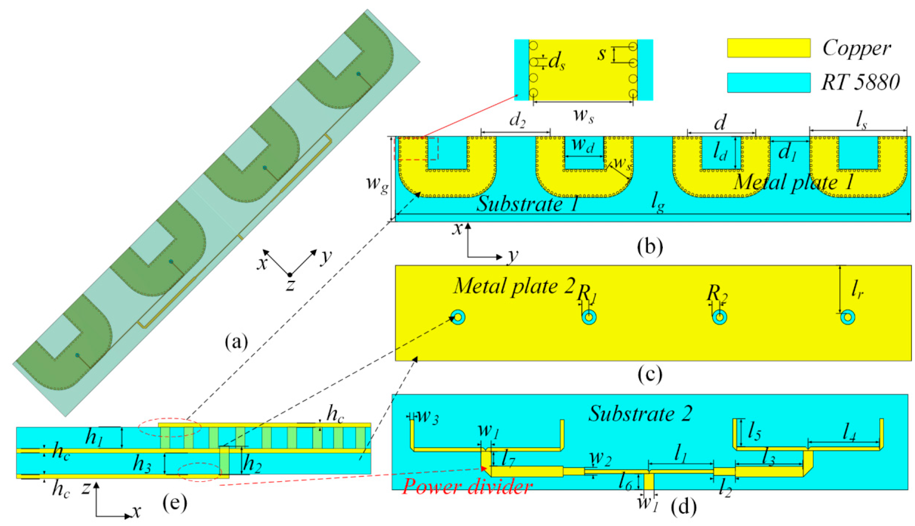
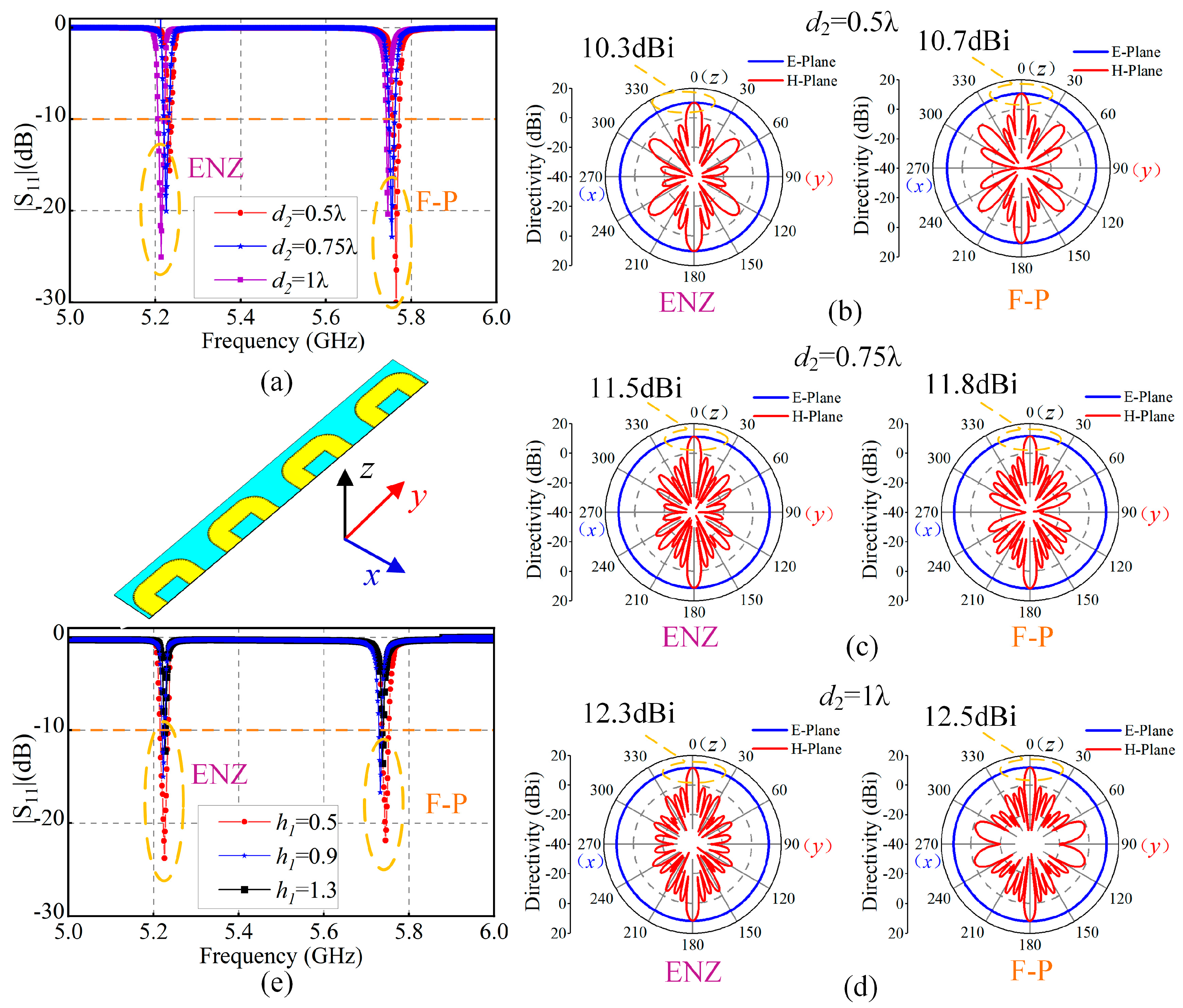
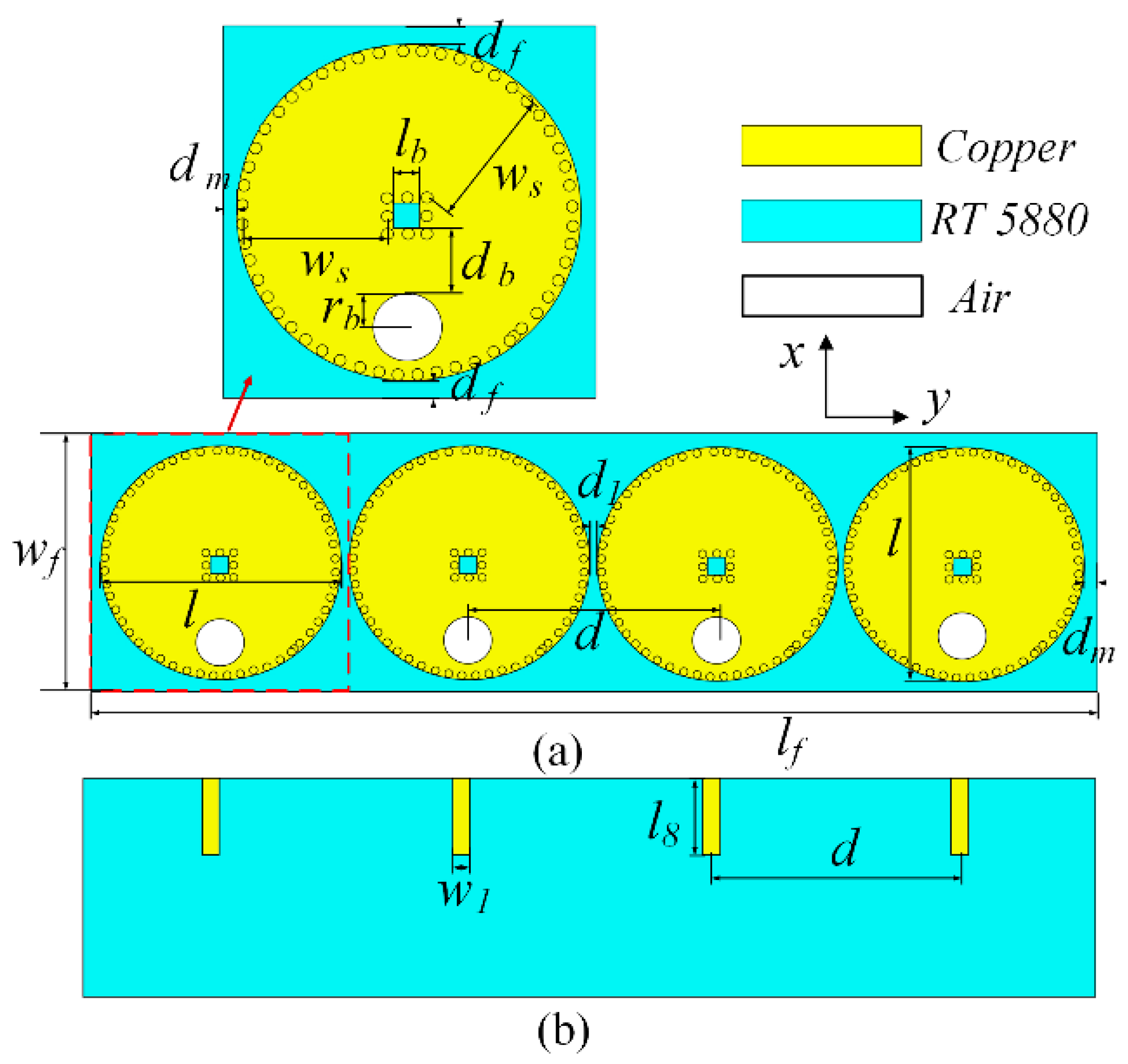
2.2. Antenna Design and Simulation

Based on the omnidirectional radiation characteristics of ENZ media studied in Section 2.1, an ENZ-FP omnidirectional antenna array is constructed in this section, as shown in Figure 3. By comprehensively balancing beamwidth, directivity, and grating lobe suppression, we select d = 0.85λ, with other parameters listed in Table 1. The antenna array consists of five components: two copper metal layers (top and bottom surfaces of the SIW), two Rogers RT5880 dielectric substrates, and one power divider. Metal plates 1 and 2 form the top and bottom surfaces of the SIW. Four sets of double-row metal vias in dielectric substrate 1 connect the upper and lower metal layers, forming a bent SIW radiation aperture, as shown in Figure 3a,b. Metal plate 2 is etched with four dielectric circular holes of radius R2 (Figure 3c). Four metal columns with radius R1 and height h2 pass through these holes, shallowly embed into dielectric substrate 1, and extend to connect with the output ports of the power divider in dielectric substrate 2. Figure 3d is a T-type 1-to-4 power divider, achieving equal-amplitude and in-phase output from four 100 Ω ports with a 50 Ω port input.
Then, we analyze the impact of key antenna parameters below. As shown in Figure 4a, when the element spacing d2 increases from 0.5λ to 1.0λ, the operating frequency shows no significant shift. However, the S11 of the ENZ mode gradually decreases, while the reflection coefficient of the F−P mode deteriorates. For the ENZ resonance, frequency stability originates from the medium’s inherent characteristics, and spacing variation primarily affects mutual coupling between elements. As d2 increases, the elements approach independent operation, impedance matching improves, and reduced mutual coupling minimizes energy loss, thereby enhancing radiation efficiency and suppressing reflections. For the F–P mode, the resonance mechanism also requires in-phase wave superposition at adjacent radiation apertures to form a stable standing-wave distribution. As the element spacing increases, the path difference Δl between electromagnetic waves propagating in adjacent elements increases, which causes the phase difference to deviate from 2nπ, violating the collaborative reflection phase condition. As a result, the constructive interference is weakened, some energy is reflected back to the source, and S11 increases.
Figure 4b–d shows that, as d2 increases, the E-plane of ENZ and F–P modes remains omnidirectional. The directivities rise from 10.3 dBi and 10.7 dBi to 12.3 dBi and 12.5 dBi, respectively. When d2 is small, the H-plane has few side lobes. But due to strong mutual coupling, the side lobe level is high. When d2 = 0.5λ, the side lobe levels are −11.1 dB and −10.5 dB, respectively. As d2 increases, the side lobe level drops to −13.5 dB and −12.7 dB. But the number of side lobes increases. When d2 = 1λ, due to the extended surface wave path, the multiple reflection mechanism of F–P resonance causes a resonant cavity effect. Energy accumulates in the end-fire direction, causing the side lobe level to surge beyond 13.2 dB at 0.75λ. Through optimization, when d2 = d = 0.85λ, the beamforming of the antenna array is more uniform, which gives the best radiation pattern stability, and the number and size of the side lobes are balanced. At this time, in the ENZ and F–P modes, the E-plane directivity is 12.0 dBi and 12.1 dBi, respectively. The H-plane side lobe levels are −13.3 dB and −13.4 dB, achieving good omnidirectional radiation performance. Figure 4e indicates that increasing the dielectric substrate thickness exacerbates dielectric and conductor losses, leading to degraded S11. Thus, thinner substrates are preferred, but a balance must be struck between radiation efficiency and mechanical stability. In this study, we select h1 = 0.508 mm, which is the standard thickness of Rogers RT5880, balancing fabrication feasibility and electrical performance.

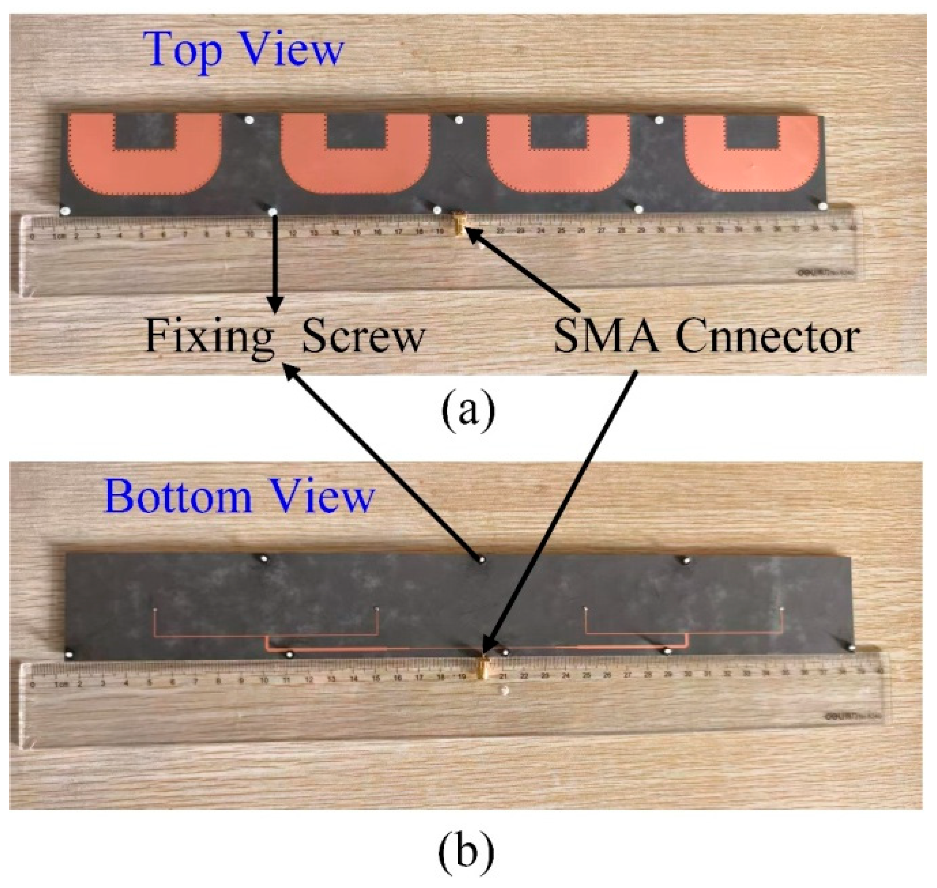
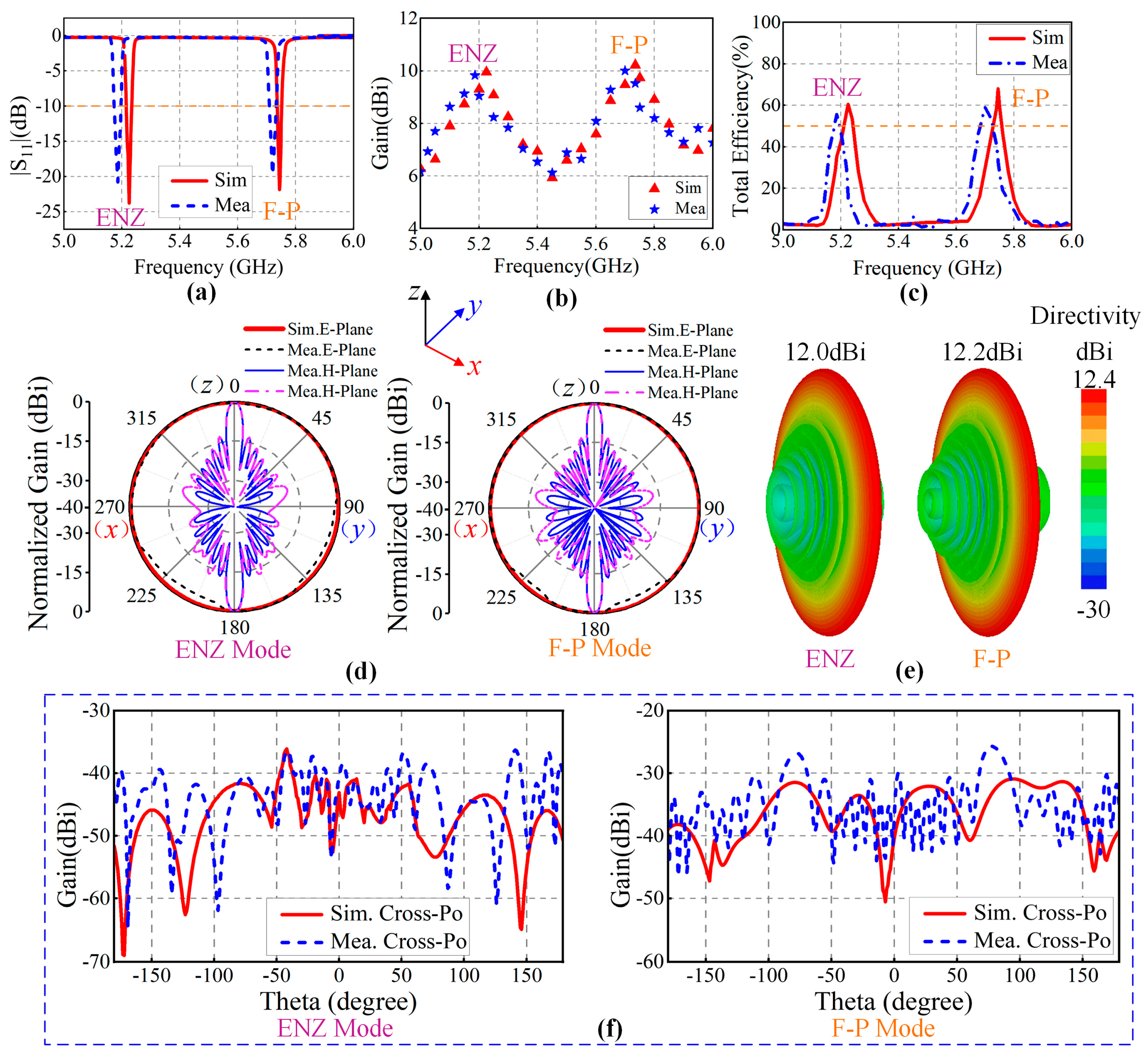
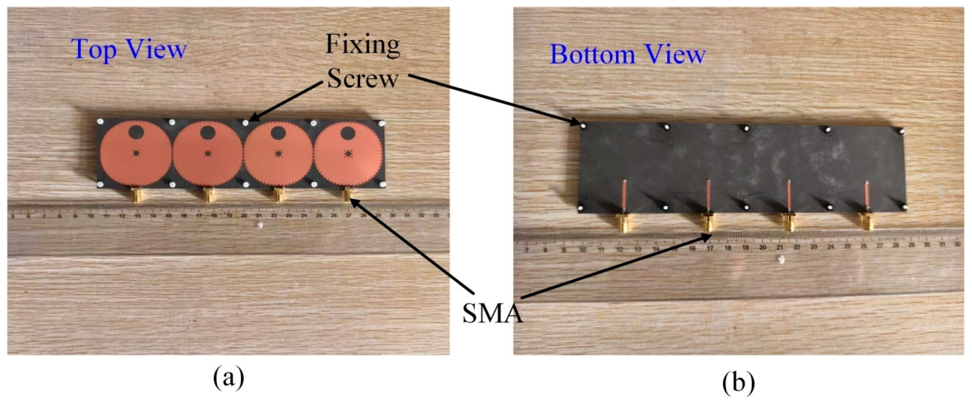
2.3. Experimental Validation

To validate the performance of the omnidirectional ENZ-F−P antenna, the antenna prototype was fabricated employing standard PCB manufacturing technology, as shown in Figure 5. All components were mechanically connected via nus to ensure radiation performance, and the bottom power divider integrated an SMA coaxial connector for 50 Ω coaxial feeding. Subsequently, the S-parameters of the antenna array were measured using a vector network analyzer, and its radiation performance was tested in a standard anechoic chamber. The relevant results are plotted in Figure 6. Figure 6a–c show that the measured minimum S11 values at the dual frequencies of 5.18 GHz and 5.72 GHz are −20 dB and −19 dB, respectively, which are consistent with the simulated results of −23 dB and −21 dB. The degradation in measured S11 and frequency deviations are attributed to fabrication tolerances and connection losses. The measured −10 dB impedance bandwidth reaches 1%, outperforming conventional ENZ antennas [14]. Furthermore, the high aperture efficiency of the ENZ medium and F−P resonance leads to measured efficiencies of 57.6% (5.18 GHz) and 59.2% (5.72 GHz), with maximum gains of 9.8 dBi and 10.1 dBi, respectively. The omnidirectional performance surpasses that of similar-sized antenna [33].
Figure 6d compares the measured and simulated E-plane/H-plane radiation patterns at ENZ and F–P frequencies, while Figure 6e shows the schematic diagram of the radiation beam. The agreement between the measured and simulated results validates the performance of the designed antenna. At both frequencies, the quasi-static field distribution of the ENZ mode and the multiple-reflection mechanism of the F–P mode can both concentrate energy in the main lobe direction, and the electric field has no phase change in the transverse direction of the waveguide (perpendicular to the propagation direction). Moreover, the phase of vertical current components are both antisymmetric around the SIW centerline, further canceling their vertical radiation and reducing cross-polarization levels below −35 dB and −25 dB. The difference in level arises because, in the ENZ mode, the field distribution is more stable, while the F–P mode’s resonance mechanism is prone to introduce more fluctuations and irregularities, leading to increased cross-polarization components.

3. Beam Scanning Antenna Array

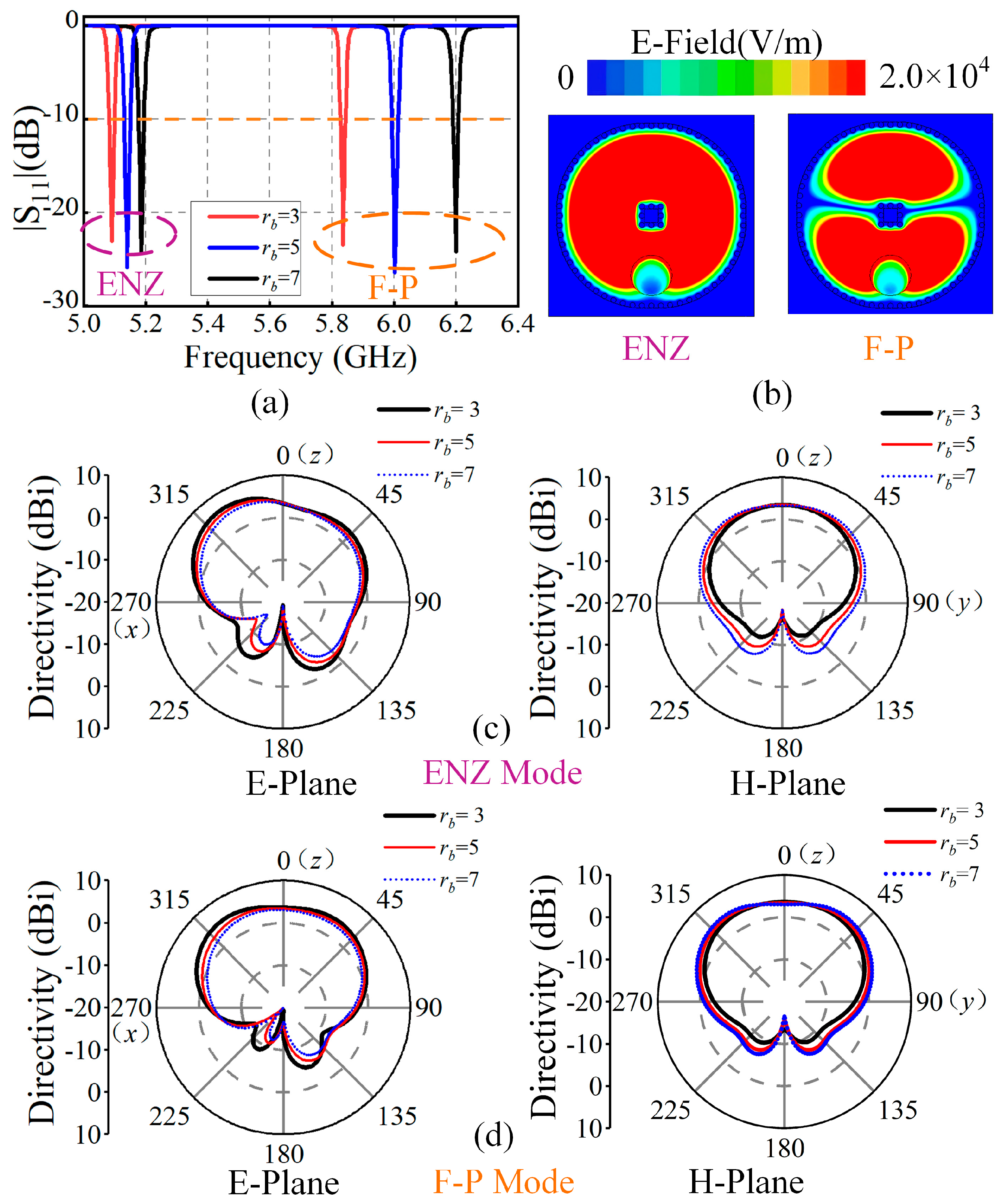
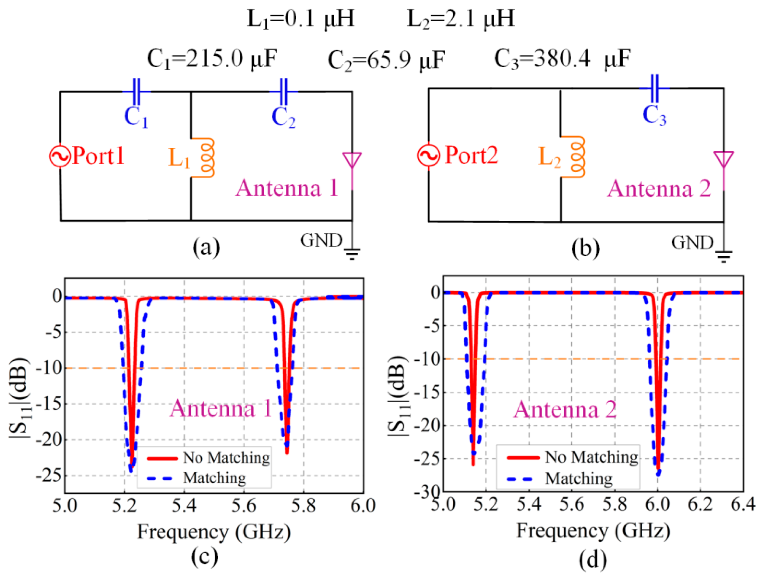
3.1. Antenna Design and Analysis

Section 2 demonstrates the application potential of ENZ media in omnidirectional antenna design. The high aperture efficiency of both ENZ and F–P modes also provides advantages such as high gain, precise beam steering, and a wide scanning range for constructing beam-scanning antenna arrays. Additionally, the geometric decoupling characteristic of ENZ media allows for flexible adjustment of the antenna shape while maintaining stable resonant frequency and radiation performance, with only a shift in the F–P mode resonant frequency. Based on this, a beam-scanning antenna shown in Figure 7 is designed by modifying the omnidirectional antenna unit structure illustrated in Figure 3.
The main antenna body retains a four-layer structure. Metal layer 1 is redesigned as a circular shape, connected to metal layer 2 through metal vias in dielectric layer 1 to form a closed SIW. A circular slot is etched at the current maximum position (Figure 7a). Compared to rectangular slots, circular slots more effectively preserve the dominant TE10 mode characteristics, suppress higher-order mode excitation, reduce coupling between Ex and Ey polarization components, and avoid efficiency loss caused by localized current cancelation, thereby enhancing gain and suppressing cross-polarization [34]. This design can achieve wide-beam characteristics in both the E-plane and H-plane, supporting wide-angle scanning while maintaining large elevation angle coverage. Four 50 Ω microstrip lines are welded at the antenna bottom to connect the feeding metal posts (Figure 7b), with detailed parameters listed in Table 2.
First, the radiation performance of a single element is analyzed by investigating the influence of slot radius rb, with results shown in Figure 8. Figure 8a shows that variations in rb have a minimal impact on the reflection coefficient magnitude. However, the ENZ frequency increases with rb, likely due to the enlarged slot reducing the antenna’s equivalent capacitance. And the F–P frequency increases slightly as it is governed by the propagation path of electric field. Figure 8b shows the electric field distribution at rb = 5, indicating that the modified unit still supports both ENZ and F–P mode. Figure 8c,d reveal that as rb increases, the E-plane beamwidth of the ENZ and F–P modes decreases, with a reduction in gain, while the H-plane beamwidth increases, but the gain remains stable. Due to the symmetric distribution of the SIW broad wall transverse current, an excessively large rb exceeding the central axis may cause transverse current cancelation. Therefore, rb is set to 5 to balance the radiation efficiency.
At this configuration, the antenna unit exhibits E-plane 3 dB beamwidths of 119.6° (ENZ mode) and 130.8° (F–P mode), with directivity of 5.39 dBi and 4.02 dBi, respectively. For the H-plane, the values are 132.1° and 3.56 dBi (ENZ mode) and 140.9° and 4.26 dBi (F–P mode). Therefore, by arranging elements along the H-plane, wide-angle beam scanning can be achieved under low-profile constraints while maintaining wide elevation angle coverage. When the circular slot on the SIW radiates, the tangential electric field Ea at the slot can be equivalent to the surface magnetic current density M = −2 n ^   × Ea = −2Eϕ r b ^ , where ϕ is the azimuth angle, and Eϕ is the tangential electric field intensity. At this time, a circular radial magnetic current is formed at the slot edge [34]. When constructing a 4-element phased array antenna using this as the phase-controlled unit, the H-plane normalized radiation pattern function can be expressed as follows:
F n o r m 2 ( θ 2 ) = J 0 ( k r b sin θ 2 ) 4 sin 2 k d ( sin θ 2 sin θ 0 ) sin k d ( sin θ 2 sin θ 0 ) 2
Here, J0 is the zero-order Bessel function, θ2 represents the angle between the radiation beam and the z-axis, and θ0 is the preset main lobe direction angle.

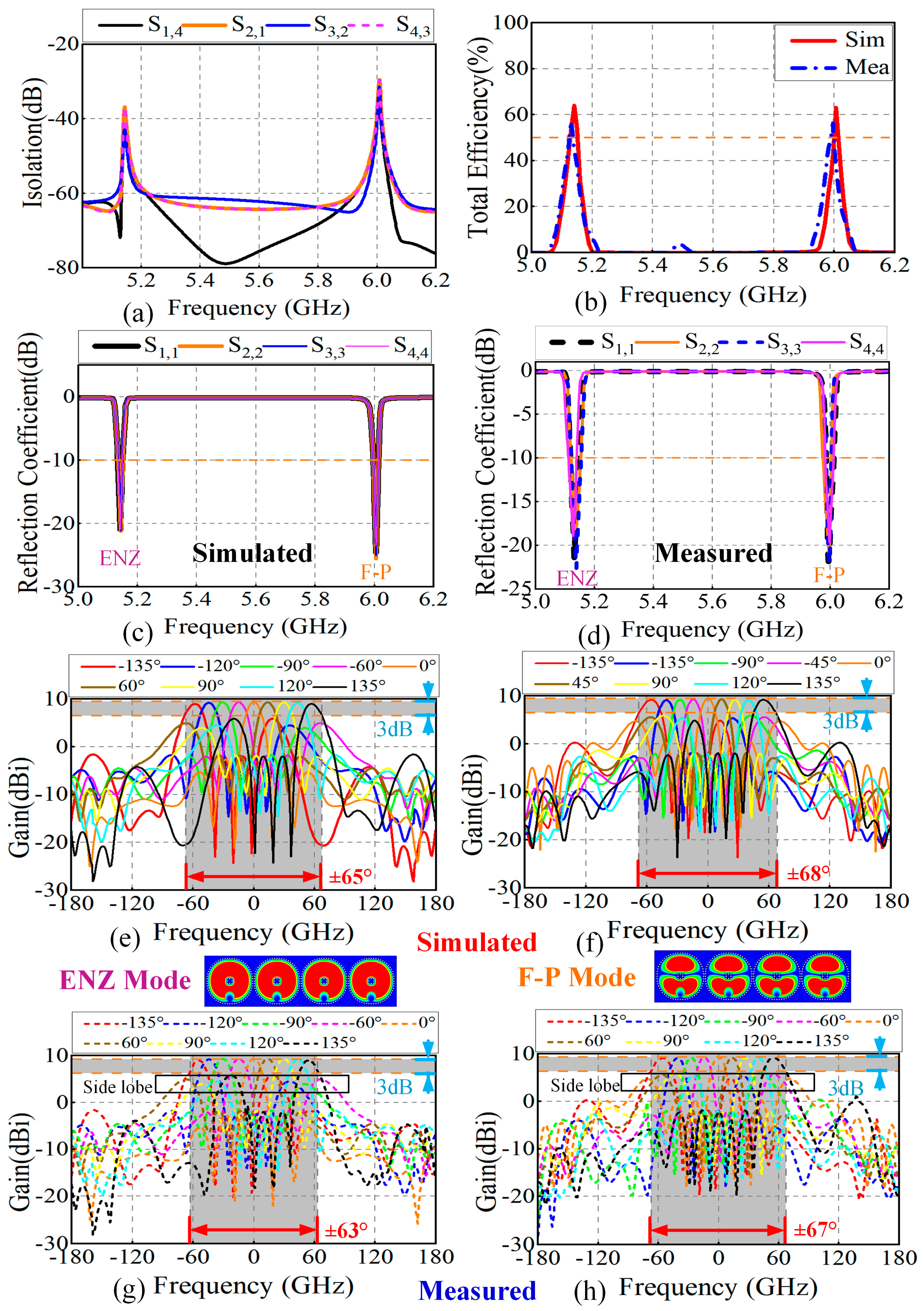
3.2. Simulation and Experimental Test

Figure 9 shows the fabricated antenna. The measured reflection coefficient and radiation performance of the antenna are shown in Figure 10. Figure 10a shows simulation results where the isolation between adjacent ports in the operating band is below −30 dB, and the weak mutual coupling ensures beam scanning stability and impedance matching. The measured maximum gains are 9.2 dBi at 5.14 GHz and 9.3 dBi at 6.0 GHz, with total efficiencies of 57.3% and 56.3%, respectively, as shown in Figure 10b. Figure 10c,d show that the measured S11 of all ports is below −18 dB at 5.14 GHz and 6.0 GHz, consistent with simulations. The expanded measured −10 dB bandwidth is attributed to additional losses introduced during antenna fabrication, which reduce the Q-factor.
Figure 10e–h compare simulated and measured beam scanning results under ENZ and F–P modes at different preset beam steering angles θ0. The simulated 3 dB beam scanning angles are ±65° and ±68°, while the measured results are ±63° and ±67°, validating the antenna’s wide-angle beam scanning capability well. And during actual scanning, the measured S11 of ENZ and F−P modes remains below −16 dB and −18 dB, respectively, indicating stable radiation efficiency. Additionally, Equation (7) reveals that wide elevation angle coverage can be maintained in the E-plane during scanning, further expanding the applicational prospects. The discrepancies between measured and simulated scanning angles may originate from practical coupling effects and non-uniform phase/amplitude distribution during feeding.
Under the ENZ mode, the maximum peak gain during scanning is 9.3 dBi, with the sidelobe level peaking at ±135-degree scanning angles at 5.7 dBi, while the peak gain is 9.0 dBi. In the F–P mode, the maximum peak gain during scanning is 9.4 dBi, and the maximum sidelobe level of 5.9 dBi occurs at ±90-degree scanning angles, with the peak gain being 9.2 dBi at this point. The standing-wave field resonance of the F–P cavity ensures in-phase superposition at the radiating aperture. The ENZ mode, leveraging its near-zero permittivity, suppresses wavefront distortion and reconstructs the wavefront phase distribution at the aperture. Both mechanisms reduce phase mismatch during scanning, stabilize the main lobe gain, and enable the antenna to maintain a sidelobe level more than 3 dB below the peak gain during scanning, highlighting its application potential. For instance, in UAV swarm communication, the antenna’s wide-angle scanning supports dynamic signal link establishment, and sidelobe-induced non-directional interference can be effectively isolated using OFDM (Orthogonal Frequency Division Multiplexing) and channel coding. In wide-area radar detection, the high main lobe gain ensures target detection sensitivity, and sidelobe signals can be filtered out via CFAR (Constant False Alarm Rate Detector) algorithms to suppress false alarms. For sidelobe-sensitive scenarios, amplitude weighting can further reduce sidelobe levels. Therefore, the dual-band beam scanning antenna array based on ENZ−FP co-design achieves breakthroughs in both low-profile height and wide scanning angles, resolving the inherent trade-off between gain fluctuation and scanning range.

4. Discussion and Conclusions

4.1. Discussion of Bandwidth Broadening

Although the ENZ and F−P modes’ collaborative resonance significantly improves the traditional ENZ antenna’s narrowband issue, with the measured bandwidth extended to more than 1%, further optimization is still required. Existing solutions like artificial low-dielectric-constant media or miniaturized metal waveguides can theoretically reduce the Q-value and broaden the bandwidth [18,35]. However, due to manufacturing complexity and integration difficulty, they are hard to apply in practice, since both antennas designed in this paper exhibit significant reactive impedance near the resonant frequency and can be fabricated using PCB technology for integration with lumped circuits. Therefore, we can load lumped components at the feed ports to construct matching networks. By compensating for the antenna’s imaginary impedance, reflection can be reduced, and the operating bandwidth is further expanded.
Figure 11a,b illustrate the impedance matching network schematics designed for the omnidirectional antenna array (Antenna 1) and beam-scanning antenna element (Antenna 2) [36]. To avoid increased loss from parasitic resistance of lumped components at high frequency, which would degrade radiation efficiency, only a first-order matching network is designed. The network is optimized and validated using ADS 2023 RF simulation software, with key parameters listed in the figure. As shown in Figure 11c,d, after loading the impedance matching networks, the −10 dB impedance bandwidth of Antenna 1 and Antenna 2 are extended to 2.4% and 2.7%, respectively, significantly outperforming traditional ENZ antennas and demonstrating enhanced engineering practicality [16,17,18,19,20].
To better measure the performance of the designed antenna, we compared it with the traditional antenna and the recent ENZ antenna, as shown in Table 3. It can be seen that the two designed antennas achieved a good balance in terms of profile height, bandwidth, radiation performance, and other aspects.

4.2. Conclusions

In this study, we introduced an innovative ENZ−FP co-resonant antenna design paradigm leveraging the spatiotemporal decoupling property of ENZ media to address the inherent narrowband limitation in ENZ-based antennas. First, we designed a dual-band omnidirectional antenna array achieving independent single-frequency tuning while overcoming the intrinsic low-profile/high-gain trade-off in conventional designs. The antenna’s directivity reached both 12.0 dBiat 5.18 GHz and 5.72 GHz, with an ultra-low profile of 0.018λ. Building on this foundation, we proposed an ENZ−FP phased beam-scanning antenna array by transforming the array element structure, achieving a wide-angle beam scanning of ±63° and ±65° on an ultra-thin substrate while maintaining large elevation angle coverage. Both antennas are fabricated based on PCB technology and experimentally validated, showing the superiority of ENZ−FP co-resonant mechanism in the design of high-performance integration antenna. Finally, through integrated matching networks, the −10 dB bandwidth expands to 2.4–2.7%, representing 4× enhancement compared to a basic ENZ antenna [18]. This work provides a high-performance antenna solution for next-generation wireless systems, significantly broadening ENZ metamaterial’s application landscape.

Author Contributions

J.L.: Investigation, Methodology, Data Curation, Formal Analysis, Writing—Original Draft. L.Z.: Investigation, Resources, Supervision, Writing—Review and Editing. D.L.: Validation, Writing—Review and Editing. H.X.: Investigation, Writing—Review and Editing. All authors have read and agreed to the published version of the manuscript.

Funding

This research was funded by the Natural Science Foundation of Hubei Province, grant number 2022CFB421, and and the person in charge is Lin Zhao.

Data Availability Statement

The data that support the findings of this study are available on request from the corresponding author. The data are not publicly available due to privacy or ethical restrictions.

Acknowledgments

We thank the editor and the anonymous reviewers for their constructive comments that helped to improve our work.

Conflicts of Interest

The authors declare no conflicts of interest.

Abbreviations

The following abbreviations are used in this manuscript:
ENZEpsilon-Near-Zero
F−PFabry–Perot
SIWSubstrate Integrated Waveguide
PCBPrinted circuit board
UAVUnmanned Aerial Vehicle
OFDMOrthogonal Frequency Division Multiplexing
CFARConstant False Alarm Rate Detector

References

  1. Qin, Y.; Han, M.; Zhang, L.; Mao, C.X.; Zhu, H. A Compact Dual-Band Omnidirectional Circularly Polarized Filtering Antenna for UAV Communications. IEEE Trans. Veh. Technol. 2023, 72, 16742–16747. [Google Scholar] [CrossRef]
  2. Ye, K.; Lu, Y.; You, Q.; Wang, K.; Xu, J.; Huang, J. Compact Dual-Band Shared-Aperture Omnidirectional Biconical Antenna for Microwave and Millimeter-Wave Applications. IEEE Trans. Antennas Propag. 2024, 72, 4594–4599. [Google Scholar] [CrossRef]
  3. Zhou, J.; Ke, Y.H.; Chen, J.X. A Dual-Polarized Omnidirectional Antenna with Small Plane Size for Indoor Distribution Applications. IEEE Antennas Wirel. Propag. Lett. 2023, 22, 1878–1882. [Google Scholar] [CrossRef]
  4. Chen, P.; Zhao, Y.; Yang, X.; Guo, R.Y.; Li, Y.; Ge, L. High-Gain Omnidirectional Transmitarray Antenna. IEEE Trans. Antennas Propag. 2023, 71, 8441–8449. [Google Scholar] [CrossRef]
  5. Chen, D.; Xue, Q.; Yang, W.; Chin, K.S.; Jin, H.; Che, W. A Compact Wideband Low-Profile Metasurface Antenna Loaded with Patch-Via-Wall Structure. IEEE Antennas Wirel. Propag. Lett. 2023, 22, 179–183. [Google Scholar] [CrossRef]
  6. Abdulkarim, Y.I.; Awl, H.N.; Muhammadsharif, F.F.; Karaaslan, M.; Mahmud, R.H.; Hasan, S.O.; Işık, Ö.; Luo, H.; Huang, S. A Low-Profile Antenna Based on Single-Layer Metasurface for Ku-Band Applications. Int. J. Antennas Propag. 2020, 2020, 8813951. [Google Scholar] [CrossRef]
  7. Ta, S.X.; Park, I. Low-Profile Broadband Circularly Polarized Patch Antenna Using Metasurface. IEEE Trans. Antennas Propag. 2015, 63, 5929–5934. [Google Scholar] [CrossRef]
  8. Liberal, I.; Engheta, N. The rise of near-zero-index technologies. Science 2017, 358, 1540–1541. [Google Scholar] [CrossRef]
  9. Liberal, I.; Engheta, N. Near-zero refractive index photonics. Nat. Photonics 2017, 11, 149–158. [Google Scholar] [CrossRef]
  10. Liberal, I.; Mahmoud, A.M.; Engheta, N. Geometry-invariant resonant cavities. Nat. Commun. 2016, 7, 10989. [Google Scholar] [CrossRef]
  11. Zhang, Y.; Li, P.; Qin, X.; Liang, P.; Wei, K.; Li, Y. Dual-Polarized Microstrip Antenna with Single-Dimension-Constraint Resonant Frequency. IEEE Trans. Antennas Propag. 2024, 72, 8365–8374. [Google Scholar] [CrossRef]
  12. Wang, Z.; Dong, Y. Novel Pattern Reconfigurable Epsilon-Near-Zero (ENZ) Antenna for Intelligent IoT Communication Applications. IEEE Internet Things J. 2024, 11, 22364–22375. [Google Scholar] [CrossRef]
  13. Liu, Z.; Zhang, Y.; Sun, W.; Li, Y. Low-Profile Epsilon-Near-Zero (ENZ) Cavity Antenna Array for Wide-Angle Beam Scanning. IEEE Antennas Wirel. Propag. Lett. 2024, 23, 2115–2119. [Google Scholar] [CrossRef]
  14. Li, H.; Zhou, Z.; He, Y.; Sun, W.; Li, Y.; Liberal, I.; Engheta, N. Geometry-independent antenna based on Epsilon-near-zero medium. Nat. Commun. 2022, 13, 3568. [Google Scholar] [CrossRef] [PubMed]
  15. Zhang, Y.; Li, H.; Zhao, Y.; Li, Y. 2-D Epsilon-Near-Zero (ENZ) Feeding Network for High-Gain Millimeter-Wave Slot Antenna Array using Bulk Silicon MEMS Technology. IEEE Trans. Antennas Propag. 2024, 72, 3055–3063. [Google Scholar] [CrossRef]
  16. Li, H.; Zhou, Z.; Zhao, Y.; Li, Y. Low-loss beam synthesizing network based on epsilon-near-zero (ENZ) medium for on-chip antenna array. Chip 2023, 2, 100049. [Google Scholar] [CrossRef]
  17. George, D.M.; Chandroth, A. 5 GHz high gain slotted SIW epsilon near zero antenna array for wireless communications. Eng. Res. Express 2020, 2, 045014. [Google Scholar] [CrossRef]
  18. Zhou, Z.; Li, Y. Effective epsilon-near-zero (ENZ) antenna based on transverse cutoff mode. IEEE Trans. Antennas Propag. 2019, 67, 2289–2297. [Google Scholar] [CrossRef]
  19. Li, H.; Zhou, Z.; Li, Y. Length-irrelevant dual-polarized antenna based on antiphase epsilon-near-zero mode. IEEE Trans. Antennas Propag. 2021, 70, 720–725. [Google Scholar] [CrossRef]
  20. Forati, E.; Hanson, G.W.; Sievenpiper, D.F. An epsilon-near-zero total-internal-reflection metamaterial antenna. IEEE Trans. Antennas Propag. 2015, 63, 1909–1916. [Google Scholar] [CrossRef]
  21. Zhiming, L.; Jens, B.; Shaobin, L.; Xiangkun, K. Investigations and prospects of Fabry-Perot antennas: A review. J. Syst. Eng. Electron. 2021, 32, 731–747. [Google Scholar] [CrossRef]
  22. Zhou, L.; Duan, X.; Luo, Z.; Zhou, Y.; Chen, X. High Directivity Fabry–Perot Antenna with a Nonuniform Partially Reflective Surface and a Phase Correcting Structure. IEEE Trans. Antennas Propag. 2020, 68, 7601–7606. [Google Scholar] [CrossRef]
  23. Jeon, Y.G.; Yun, G.R.; Kim, J.; Kim, D. Polarization Reconfigurable High-Gain Fabry–Perot Cavity Antenna. IEEE Trans. Antennas Propag. 2022, 70, 7727–7734. [Google Scholar] [CrossRef]
  24. Zhou, Z.; Li, Y.; He, Y.; Zhang, Z.; Chen, P.Y. A Slender Fabry–Perot Antenna for High-Gain Horizontally Polarized Omnidirectional Radiation. IEEE Trans. Antennas Propag. 2021, 69, 526–531. [Google Scholar] [CrossRef]
  25. Hussain, N.; Jeong, M.J.; Park, J.; Kim, N. A Broadband Circularly Polarized Fabry-Perot Resonant Antenna Using A Single-Layered PRS for 5G MIMO Applications. IEEE Access 2019, 7, 42897–42907. [Google Scholar] [CrossRef]
  26. Sadeghzadeh, R.A.; Zarrabi, F.B. Metamaterial Fabry–Perot cavity implementation for gain and bandwidth enhancement of THz dipole antenna. Optik 2016, 127, 5181–5185. [Google Scholar] [CrossRef]
  27. Syrytsin, I.; Zhang, S.; Pedersen, G.F.; Morris, A.S. Compact Quad-Mode Planar Phased Array with Wideband for 5G Mobile Terminals. IEEE Trans. Antennas Propag. 2018, 66, 4648–4657. [Google Scholar] [CrossRef]
  28. Wang, Z.; Zhao, S.; Dong, Y. Metamaterial-Based Wide-Beam Dielectric Resonator Antenna for Broadband Wide-Angle Beam-Scanning Phased Array Applications. IEEE Trans. Antennas Propag. 2022, 70, 9061–9072. [Google Scholar] [CrossRef]
  29. Yang, G.; Li, J.; Zhou, S.G.; Qi, Y. A Wide-Angle E-Plane Scanning Linear Array Antenna with Wide Beam Elements. IEEE Antennas Wirel. Propag. Lett. 2017, 16, 2923–2926. [Google Scholar] [CrossRef]
  30. Yang, G.; Zhang, S. Dual-Polarized Wide-Angle Scanning Phased Array Antenna for 5G Communication Systems. IEEE Trans. Antennas Propag. 2022, 70, 7427–7438. [Google Scholar] [CrossRef]
  31. Feng, X.; Wu, K. Guided-wave and leakage characteristics of substrate integrated waveguide. IEEE Trans. Microw. Theory Tech. 2005, 53, 66–73. [Google Scholar] [CrossRef]
  32. Rotman, W. Plasma simulation by artificial dielectrics and parallel-plate media. IRE Trans. Anntenas Propag. 1962, 10, 82–95. [Google Scholar] [CrossRef]
  33. Chang, L.; Li, Y.; Zhang, Z.; Feng, Z. Horizontally Polarized Omnidirectional Antenna Array Using Cascaded Cavities. IEEE Trans. Antennas Propag. 2016, 64, 5454–5459. [Google Scholar] [CrossRef]
  34. Balanis, C.A. Antenna Theory: Analysis and Design; John Wiley & Sons: Hoboken, NJ, USA, 2015. [Google Scholar]
  35. Li, P.; Yan, W.; Wang, S.; Fu, P.; Zhang, Y.; Li, Y. Engineering Epsilon-Near-Zero Media with Waveguides. Adv. Phys. Res. 2024, 3, 2400070. [Google Scholar] [CrossRef]
  36. Rao, R.S. Microwave Engineering; PHI Learning Pvt. Ltd.: New Delhi, India, 2015. [Google Scholar]
  37. Li, J.; Zhao, L.; Wu, H. A Novel Highly Directional Antenna Array Based on Epsilon-Mu-Near-Zero (EMNZ) with Air Gap Structure. IEEE Trans. Antennas Propag. 2024, 73, 2357–2368. [Google Scholar] [CrossRef]
  38. Liu, Z.; Zhou, Z.; Li, Y.; Li, Y. Integrated epsilon-near-zero antenna for omnidirectional radiation. Appl. Phys. Lett. 2021, 119, 151904. [Google Scholar] [CrossRef]
Figure 1. Schematic diagram of ENZ-FP omnidirectional antenna design and simulation results. Structure diagram of straight SIW (a) and curved SIW (c). Vector electric field distribution diagram of straight type (b) and curved type (d). Reflection coefficient (e) and radiation beam (f) in both modes.
Electronics 14 02012 g001
Figure 2. Reflection coefficient (a) of the ENZ antenna at different spacing d and electric field distribution and beam variation (bd).
Electronics 14 02012 g002
Figure 3. Structure diagram of the omnidirectional ENZ-F–P antenna array. (a) Perspective view, (b) top view, (c) schematic diagram of metal plate 2, (d) bottom view, (e) side view.
Electronics 14 02012 g003
Figure 4. Reflectance coefficient (a) and radiation patterns (bd) of antenna array with variation in interelement spacing d2. (e) Reflectance coefficient with different thickness h1.
Electronics 14 02012 g004
Figure 5. Photograph of the fabricated prototype of the proposed omnidirectional antenna array. (a) Top view, (b) bottom view.
Electronics 14 02012 g005
Figure 6. Comparison of measured simulation results of omnidirectional antenna array. (a) Reflection coefficient, (b) maximum gain, (c) total efficiency, (d) normalized radiation patterns of E-plane and H-plane, (e) radiation beam diagram (f), cross−polarization of ENZ and F–P resonance.
Electronics 14 02012 g006
Figure 7. Schematic diagram of beam-scanning antenna array. (a) Top view, (b) bottom view.
Electronics 14 02012 g007
Figure 8. Radiation performance changes in the antenna unit at rb = 3, 5, 7. (a) S11, (b) Electric field distribution at rb = 5, (c) E-Plane and H-Plane radiation patterns of the antenna in ENZ mode and (d) in F−P mode.
Electronics 14 02012 g008
Figure 9. Photograph of the fabricated prototype of the proposed beam scanning antenna array. (a) Top view, (b) bottom view.
Electronics 14 02012 g009
Figure 10. Simulation and measured results of beam-scanning antenna array. (a) Simulation isolation, (b) total efficiency, (c) simulation and (d) measured reflection coefficients; simulated (e) and measured (g) beam scanning results in ENZ mode, simulation (f) and measured (h) beam scanning results in F–P mode.
Electronics 14 02012 g010
Figure 11. Impedance matching network circuit diagram of antenna 1 (a) and antenna 2 (b); comparison of reflection coefficients between antenna 1 (c) and antenna 2 (d) before and after matching.
Electronics 14 02012 g011
Table 1. Detailed parameters of omnidirectional antenna array.
ParameterValue (mm)ParameterValue (mm)ParameterValue (mm)
lg370l133.7l210.3
l352.5l448.05ls70.3
l512.4l64.1lr25.2
ld17wg48.5w11.5
w20.82w30.4ws20
wd27.7s2.4ds1.3
hc0.035h10.508h20.635
h30.508R10.6R21.3
l75.5d2 = d27.7d149
Table 2. Part of detailed parameters of beam-scanning antenna array.
ParameterValue (mm)ParameterValue (mm)ParameterValue (mm)
lf189lb3.5l45.9
d1d146.9lr25.2
ld17wf49.9l818.3
df2dm1.2rb5
db8.2w11.5
Table 3. Comparison of the proposed design with other related antennas.
ReferenceAntenna TypeSize (mm)Element NumberCF (GHz)Gain (dBi)Profile (λ)Radiation ModeBandwidth
[1]Patch25 × 2512.4\5.80\1.50.042Omni4.1%
[15]ENZ22 × 516 × 1063.521.80.3Dir.0.1%
[24]F−P360 × 1852.58.520.032Omni.3.6%
[33]PLs168 × 1855.958.670.04Omni.2.0%
[29]Microstrip350 × 4094.012.80.23B-S(±70°)15%
[30]Microstrip300 × 608513.20.71B-S(±60°)12%
[37]EMNZ30010513.750.5Dir.0.1%
[38]ENZ214 × 2447.75No Given0.06Omni.0.4%
Ant.1ENZ−FP370 × 48.545.18\5.729.8\10.10.018Omni.2.4%
Ant.2ENZ−FP189 × 49.945.14\6.09.3\9.40.018B-S(±63°\±67°)2.7%
CF = center frequency; Dir. = directional; Omni. = omnidirectional; PLs = parallel strip-lines; B-S = beam scanning.
Disclaimer/Publisher’s Note: The statements, opinions and data contained in all publications are solely those of the individual author(s) and contributor(s) and not of MDPI and/or the editor(s). MDPI and/or the editor(s) disclaim responsibility for any injury to people or property resulting from any ideas, methods, instructions or products referred to in the content.

