1. Introduction
Hybrid stepper motors (HSMs) are commonly used in industrial automation for position control, typically operating in open-loop modes such as full stepping or half-stepping [
1]. To address issues such as vibration at low speeds and noise reduction, microstepping control schemes have been proposed. However, open-loop control still faces challenges such as step loss and low efficiency. To mitigate step loss and enhance the dynamic performance of the motor, enabling its application in high-precision scenarios, research on closed-loop control with position sensors has gained significant attention.
Closed-loop microstepping control originates from the open-loop control schemes of stepper motors, where the target phase voltage varies with the rotor position. The higher the microstepping resolution, the closer the phase voltage approximates a sinusoidal waveform, resulting in smoother operation. In [
2], a displacement-dependent voltage set is employed to maximize electromagnetic torque while minimizing torque ripple, demonstrating robustness against variations in motor parameters and load conditions. Reference [
3] proposes a phase-compensated microstepping scheme, which reduces steady-state position errors without requiring position feedback.
With the advancement of embedded processors and the reduction in hardware costs, the application of vector control (VC) using DQ transformation for HSMs has gained increasing attention [
4,
5,
6,
7]. VC, also known as field-oriented control (FOC), demonstrates superior motion performance compared to microstepping due to its current-based control approach [
8]. In conventional VC schemes, proportional–integral (PI) controllers are typically employed for current and speed tracking. Numerous studies have focused on designing advanced controllers to replace PI controllers to further enhance motor performance. For instance, reference [
9] proposes a torque expression incorporating third-harmonic torque pulsations, which is applied to the calculation of the Q-axis reference current. This approach effectively addresses the mechanical resonance issues of HSMs at low speeds, although it involves numerous parameters, making tuning challenging. Reference [
10] introduces an adaptive feed-forward proportional-resonant (AFPR) current controller based on neural networks, where the controller parameters are adaptively obtained using neural networks, significantly improving current tracking performance. In reference [
11], an augmented observer (AOB) is designed to estimate all motor states and disturbances, and a nonlinear controller is developed based on disturbance estimation errors, enhancing position tracking performance under disturbances. To improve motor performance at high speeds, reference [
12] proposes a speed damping method combined with an improved PI controller to reduce vibrations at high speeds. Additionally, reference [
13] presents a hybrid control scheme integrating sliding mode control with PI control, achieving small steady-state errors and strong disturbance rejection capabilities at high speeds.
In recent years, several control schemes for stepper motors without DQ transformation have been proposed. These schemes directly track the target currents in the stator reference frame rather than the rotor reference frame, thereby enhancing the control performance of HSMs. For instance, reference [
14] eliminates the DQ transformation while achieving performance comparable to traditional VC, simultaneously reducing the computational burden on hardware. Building on this, reference [
15] designs current tracking controllers and position controllers for the ab-axes based on Lyapunov theory, significantly improving position tracking performance. Furthermore, reference [
16] proposes a Lyapunov-based controller incorporating a nonlinear observer, effectively reducing current errors and enhancing position accuracy. To address the phase lag issue caused by current filtering, reference [
17] introduces a proximate in-phase current estimator (PIpCE), which minimizes torque ripple and avoids step loss and reversal problems.
Conventional VC schemes typically use simplified HSMs models that neglect the complexity of spatial magnetic fields, leading to inaccurate reference current calculation, while current tracking controller designs rely on inductance parameters. This paper proposes a novel HSM vector control scheme without DQ transformation: the reference current is calculated using stator flux linkage information, fully considering the motor’s magnetic field distribution characteristics; a stator-frame current tracking controller is designed based on Lyapunov stability theory, achieving precise current control without requiring inductance parameters; meanwhile, a nonlinear torque modulation controller directly outputs the target torque, simplifying the control structure. This scheme optimizes the vector control framework and effectively improves HSM position control performance.
This paper is organized as follows.
Section 2 analyzes and establishes the mathematical model of the HSMs.
Section 3 presents the overall control strategy, including the nonlinear torque modulator, the optimal reference current algorithm, and the Lyapunov-based current tracking controller.
Section 4 provides an analysis of the closed-loop stability of the system.
Section 5 demonstrates the simulation and experimental results. Finally,
Section 6 concludes this paper.
2. Mathematical Model of Hybrid Stepper Motors
The HSM studied in this paper can be considered a type of permanent magnet synchronous motor (PMSM). Its mathematical model consists of electromagnetic and electromechanical equations. Assuming that the stator fluxes of the two phases vary periodically with the rotor angular position and have a phase difference of
, the fundamental mathematical equations are given as follows: [
18]:
where
and
are the currents of phases [A],
and
are the voltages of phases [V],
R is the resistance of the phase windings [
],
and
are the stator flux linkages of phases [Wb], and
and
represent the rotor angular position [rad] and mechanical angular speed of the rotor shaft [rad/s], respectively.
J is the rotor moment of inertia [Kg· m
2], and
B is the viscous damping coefficient [N· m· s/rad].
and
are the electromagnetic torque and load torque [N· m], respectively. The electromagnetic torque equation based on stator flux, which links the electromagnetic and mechanical equations, is expressed as follows:
For HSMs,
denotes the number of rotor teeth and equals the number of magnetic pole pairs on the rotor. The representation of stator flux is critical. A nonlinear electromagnetic system, the nonuniform and nonstationary magnetic field of permanent magnets, and other phenomena are considered in the equations for
and
, as follows [
2]:
where
L is the phase inductance [H], and
is the rotor permanent magnet flux linkage. For motors with a nearly sinusoidal magnetic field distribution, such as surface-mounted PMSMs,
. However, HSMs differ from surface-mounted PMSMs due to their unique multi-tooth stator–rotor structure and axial magnetic field distribution, which introduce non-negligible higher-order harmonics in the permanent magnet flux linkage. As a result, the spatial distribution of the magnetic field is not ideally sinusoidal. For non-ideal sinusoidal magnetic field distributions,
with
. Moreover, the magnetic field distribution of different HSMs may vary due to manufacturing tolerances, making it challenging to establish an accurate mathematical model for HSMs.
This paper establishes the mathematical model of HSMs based on Equations (
1) and (
3) for simulation analysis. Considering the non-ideal magnetic field distribution, a current optimal control strategy is designed, which significantly improves the position tracking performance of the HSMs.
4. Analysis of Closed-Loop Stability
In this section, we analyze the closed-loop stability of the system. The error dynamics of the closed-loop system consist of the motion error dynamics and the current error dynamics. We define a new closed-loop error as follows:
The closed-loop error dynamics can be expressed as follows:
where the system matrix
is given as follows:
Equation (
24) represents a linear parameter-varying (LPV) system. Although
and
are a complex function of current and rotor position according to (
3), considering the physical reality, the stator flux is bounded under normal motor operation with finite speed and load. Furthermore, the eigenvalues of the system matrix
can be derived from the characteristic determinant:
Since
,
, and
are positive constants, it follows from (
26) that all eigenvalues of matrix
are negative, making
a Hurwitz matrix. This holds true for any
and
. Therefore, the linear parameter-varying system represented by the closed-loop error dynamics (
24) is robustly stable about the origin.
5. Simulation and Experimental Results
To demonstrate the position tracking performance of the proposed method, simulations and experiments were conducted. A control scheme using the same position controller from reference [
15] was designed as a comparative scheme, expressed as follows:
For clarity, the proposed method in this paper is referred to as Scheme 1, while the control scheme in [
15] is referred to as Scheme 2. In both simulations and experiments of Scheme 1, identical control parameters were used: the torque modulation controller gains were set to
= 300 and
= 0.025, while the current tracking controller gain was
= 0.1. These values were carefully selected to ensure optimal tracking performance and system stability. A hybrid stepper motor, model 57CME23-z, produced by Leadshine, was used for the experiments. The motor parameters are listed in
Table 1. The control block diagram of the proposed scheme is shown in
Figure 1.
5.1. Simulation
Simulations were conducted using MATLAB/Simulink. In the motor model (
3), the coefficients of the higher-order terms were set as follows:
,
, and
. Higher-order terms were neglected due to their negligible magnitude; thus, their coefficients were set to zero. The target position trajectory is shown in
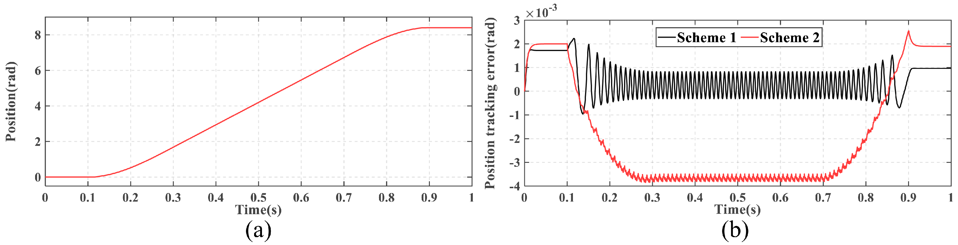
Figure 2a, with a constant speed of
rad/s during the steady-state phase.
Figure 2b illustrates the position tracking errors of both schemes. During the constant-speed phase, the position tracking error of Scheme 1 is 0.0008 rad, significantly smaller than the 0.0038 rad error of Scheme 2. At the end of motion, the positioning error of Scheme 1 is 0.001 rad, which is also better than the 0.0019 rad error of Scheme 2. These results demonstrate that, despite using the same position controller, the proposed scheme achieves superior position tracking performance.
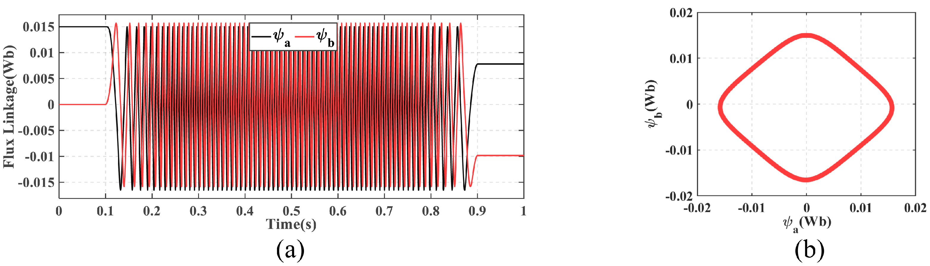
Figure 3 shows the two-phase stator flux linkages and the locus of stator flux linkage. When higher-order harmonics are considered, the stator flux trajectory approximates a diamond shape rather than the ideal circular shape, which is a significant distinction from surface-mounted PMSMs.
Figure 4 presents a comparative analysis of the current tracking performance and voltage curves in both control schemes. The experimental results demonstrate that Scheme 2 exhibits peak current and voltage values of approximately 0.36 A and 7.0 V, respectively, while Scheme 1 shows corresponding values of approximately 0.25 A and 6.4 V. These comparative data indirectly indicate the superior efficiency of the proposed current loop. During motor operation, Scheme 2 manifests a maximum current tracking error of 0.03 A, whereas Scheme 1 maintains near-zero tracking error. These findings conclusively demonstrate that the current tracking controller developed in this study achieves significantly enhanced performance when implemented in HSM models incorporating stator magnetic field higher-order harmonics.
5.2. Experiment
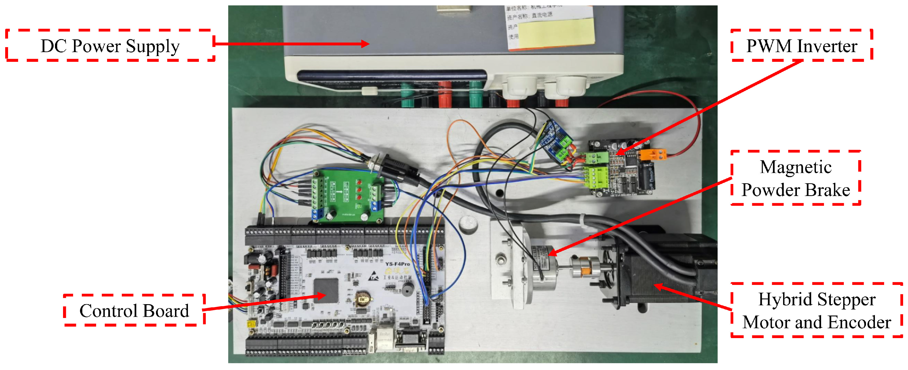
To validate the practical performance of the proposed method, experiments were conducted. The experimental setup is shown in
Figure 5. The control algorithm was implemented using a microcontroller, the STM32F407IGT6 from STMicroelectronics, programmed in C language. The power drive utilized a conventional design with eight MOSFETs forming a dual H-bridge, operating at a PWM switching frequency of 50 kHz with a DC input voltage of 24 V. Phase currents were measured using ACS712ELC Hall-effect current sensors and converted into digital signals by the microcontroller’s built-in 12-bit ADC (analog-to-digital converters). The stepper motor was equipped with a 1000-line incremental encoder operating in 4x interpolation mode, providing 4000 pulses per revolution to record the rotor position. The current control loop ran at 36 kHz, as the electrical dynamics are significantly faster than the mechanical dynamics, while the position control loop operated at a lower frequency of 3.6 kHz. A magnetic powder brake was used to generate a constant load torque, set to 0.03 N·m for this experiment.
Compared to the simulation, the duration of constant-speed motion was extended to obtain more signal data, with the constant speed maintained at
rad/s.
Figure 6 illustrates the position tracking errors of both methods, with quantitative metrics systematically compared in
Table 2. The proposed scheme achieves superior control performance, exhibiting a steady-state error of 0.003 rad during constant-speed operation and positioning error <0.0015 rad at rest, representing 85.5% and 85.8% reductions in IAE (Integral Absolute Error)and ITAE (Integral Time Absolute Error) relative to Scheme 2. These improvements persist under both dynamic and static conditions, as evidenced by the integral error metrics. Since both strategies employ identical torque modulation, the enhanced precision is directly attributable to our current reference generation and current tracking controller.
Figure 7 illustrates the current tracking performance and voltage curves in both control schemes, with all data presented in raw form without filtering or processing. During constant-speed operation, both schemes demonstrate comparable peak current and voltage amplitudes of approximately 0.3 A and 6 V, respectively. With the implemented 100 Hz data transmission frequency, the current waveforms exhibit well-defined periodic variations during motor operation. Comparative analysis of current tracking performance demonstrates the proposed scheme’s superiority across dynamic and static operations. As shown in
Figure 7, Scheme 2 exhibits significantly increased errors during motion (maximum instantaneous error: 0.15 A) versus stationary conditions, with integral metrics confirming its limitations through elevated IAE/ITAE values in
Table 3. In contrast, the proposed scheme maintains consistent precision throughout all operational states, achieving maximum instantaneous errors below 0.1 A while achieving 53.2% and 52.1% reductions in current tracking IAE and ITAE, respectively. These improvements—quantitatively documented in
Table 3—combine transient error suppression with cumulative error reduction, conclusively validating the enhanced dynamic performance of our Lyapunov-based controller.
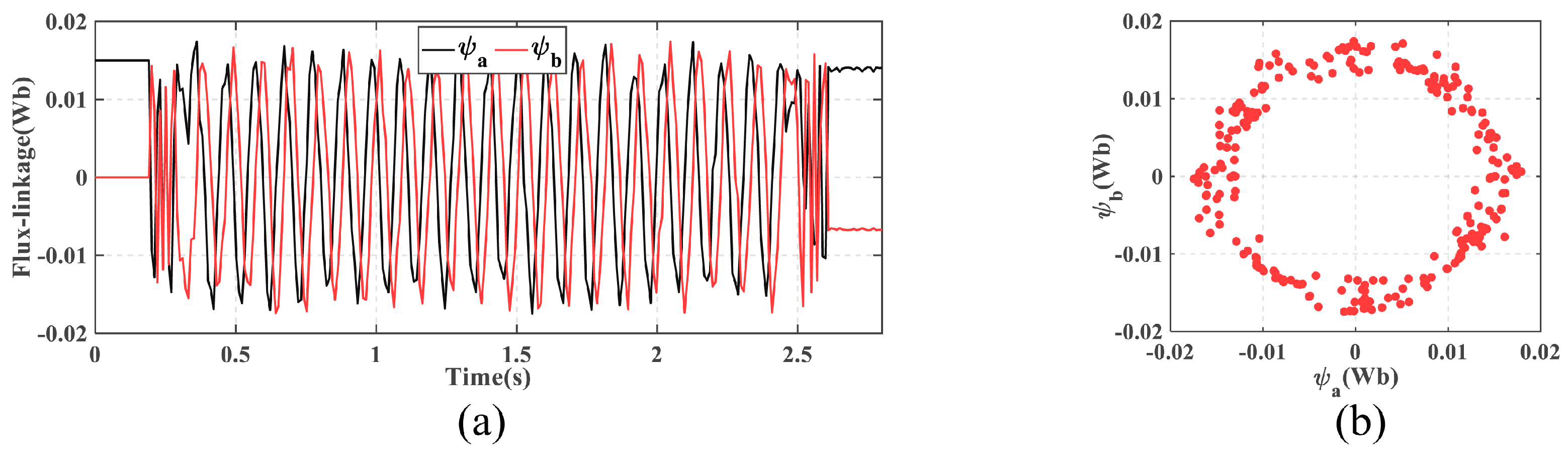
Figure 8 shows the flux linkage curves of the two windings and the locus of stator flux linkage. Before startup, the D-axis is aligned with the a-axis, with the initial stator flux of the a-phase set to 0.015 Wb and the b-phase flux set to 0 Wb. During motor operation, the stator flux varies periodically, with the maximum value exceeding 0.015 Wb due to the addition of the armature flux generated by the phase currents. The stator flux trajectory forms an irregular circle, reflecting the non-ideal magnetic field distribution of the HSM. This is caused by factors such as the multi-tooth rotor structure and manufacturing tolerances, which are inherent characteristics of HSMs.
6. Conclusions
In this paper, we propose a novel closed-loop control scheme to enhance the position tracking performance of HSMs. First, considering the complex magnetic field distribution of HSMs, we introduce an algorithm to calculate the optimal phase current based on the stator flux linkage. This algorithm dynamically computes the minimum target current according to real-time stator flux variations while eliminating the need for DQ transformation. To address the high-frequency variations in stator currents, a current tracking controller based on Lyapunov stability theory is designed. This controller achieves current tracking in the stator reference frame with a simple structure and does not require motor inductance parameters.Finally, simulations and experiments were conducted using nonlinear torque modulation as the position controller.
The proposed scheme achieves a steady-state position tracking error of less than 0.003 rad during constant-speed operation and a positioning error of less than 0.0015 rad at rest, significantly outperforming comparable control schemes. By enabling high-precision current tracking with minimal dependency on motor parameters, this method enhances the viability of HSMs in applications demanding both static positioning accuracy and dynamic trajectory control, such as precision robotic assembly and semiconductor manufacturing equipment. Its computational efficiency and compatibility with low-cost embedded platforms further broaden its potential for closed-loop motion systems in industrial automation, where cost–performance balance is critical.


