Article

Introducing the Adaptive Nonlinear Input Impedance Control Approach for MPPT of Renewable Generators

by
Mahdi Salimi
Faculty of Engineering and Science, University of Greenwich, Kent ME44TB, UK
Electronics 2025, 14(10), 1960; https://doi.org/10.3390/electronics14101960
Submission received: 3 April 2025 / Revised: 24 April 2025 / Accepted: 9 May 2025 / Published: 11 May 2025

Abstract

:
This paper proposes a novel maximum power point tracking (MPPT) strategy for renewable energy systems using Input Impedance Control (I2C) in power electronic converters, combined with an adaptive nonlinear controller. Unlike conventional voltage- or current-based methods, the I2C-MPPT approach leverages the maximum power transfer theorem by dynamically matching the converter’s equivalent input impedance to the source’s internal impedance. The adaptive nonlinear controller, designed using the Lyapunov stability theory, estimates system uncertainties and provides superior performance compared to traditional Proportional–Integral (PI) controllers. The proposed approach is validated through both simulations in MATLAB and experimental implementation using a Digital Signal Processor (DSP)-based controller. Practical results confirm the controller’s effectiveness in maintaining maximum power transfer under dynamic variations in source parameters, demonstrating improved settling time and robust operation. These findings underscore the potential of the I2C approach for enhancing the efficiency and reliability of renewable energy systems.

1. Introduction

The global shift toward renewable energy resources has accelerated due to the challenges posed by global warming, the depletion of fossil fuels, and the increasing demand for sustainable energy solutions. Renewable generators such as PhotoVoltaic (PV) systems, thermoelectric generators, and wind turbines offer promising alternatives to conventional energy sources. However, the inherent variability of these systems, driven by fluctuating environmental factors, presents significant challenges in achieving efficient energy utilisation. One effective way to address these challenges is through MPPT techniques, which aim to maximise energy extraction under varying operating conditions.
Renewable energy systems, particularly solar PV systems, are increasingly deployed in off-grid and remote regions where centralised electricity infrastructure is unavailable or unreliable. These systems are vital for rural electrification [1], powering telecommunication towers [2], and supporting disaster relief operations [3]. In such applications, energy autonomy is critical, and even minor inefficiencies in power extraction can significantly impact system reliability. For example, in remote healthcare facilities, a stable power supply from PV systems ensures the operation of medical equipment, while in agricultural IoT (Internet of Thing) networks, consistent energy harvesting enables the real-time monitoring of crop conditions [4]. The effectiveness of these systems heavily depends on the ability to maximise energy extraction under rapidly changing environmental conditions, which remains a key challenge for conventional MPPT techniques.
MPPT techniques are not limited to PV systems but are also critical for optimising energy extraction from thermoelectric generators (TEGs) [5], wind turbines [6], piezoelectric harvesters [7], and wave energy converters [8]. Each of these applications requires tailored MPPT strategies due to their distinct electrical characteristics—for instance, TEGs exhibit low-voltage, high-current outputs, while wind turbines face variable torque–speed relationships. Conventional MPPT methods typically rely on voltage or current control which may fail to adapt to dynamic source impedances. However, from a fundamental perspective, MPPT aligns with the maximum power transfer theorem, where optimal energy extraction occurs when the load impedance matches the source impedance. This paper proposes a paradigm shift: instead of tracking voltage or current setpoints, the I2C-MPPT directly regulates the converter’s equivalent input impedance to match the source impedance. By treating MPPT as an impedance control problem, this approach offers a unified, physics-based solution adaptable to diverse renewable generators, overcoming the limitations of heuristic or application-specific voltage/current control methods.
Among the most widely used MPPT methods are the Perturb and Observe (P&O) and Incremental Conductance (INC) techniques [9]. These methods are valued for their simplicity and ease of implementation, but they suffer from critical drawbacks. Specifically, P&O methods introduce steady-state oscillations around the Maximum Power Point (MPP) and struggle to adapt to rapid environmental changes. Moreover, although these methods incorporate feedback mechanisms, they are not classified as model-based controllers from a control theory perspective. Consequently, their effectiveness diminishes in complex and dynamic operating scenarios where more robust and adaptive solutions are required [10].
Several advanced MPPT techniques have been proposed to enhance the efficiency and response time of PV systems. One such approach is the use of Fuzzy Logic Control (FLC) and Model Predictive Control (MPC), as analysed in [11]. While FLC demonstrates superior adaptability to dynamic irradiance changes, achieving an average MPPT efficiency of 98.298%, it still relies on heuristic rule-based decision-making, which can be challenging to tune optimally for varying operating conditions. Additionally, FLC methods often exhibit steady-state oscillations around the MPP due to their lack of a precise convergence criterion. On the other hand, MPC provides predictive capabilities but requires a high computational burden, leading to slower response times compared to FLC. Moreover, MPC depends on accurate system modelling, making it less robust against parameter uncertainties.
The artificial intelligence-based MPPT methods proposed in [12] offer predictive capabilities by forecasting irradiance variations and estimating the MPP voltage through a feedforward neural network. While this approach demonstrates superior tracking performance across different weather conditions, its reliance on historical irradiance data makes it susceptible to prediction errors in rapidly fluctuating environments. Furthermore, neural network-based MPPT methods often require extensive training datasets and computationally intensive real-time implementation, limiting their feasibility in embedded system applications.
Metaheuristic optimisation algorithms, such as the improved Hunter–Prey Optimisation (IHPO) technique proposed in [13], have also been explored for MPPT applications. These algorithms aim to overcome local optima challenges in multi-peaked power-voltage characteristics under shading conditions. While IHPO achieves high efficiency (98.75%) and global tracking capabilities, it requires iterative searches, leading to longer convergence times compared to direct model-based approaches. Additionally, its dependence on population-based optimisation can introduce transient tracking delays and increased computational overhead, making it less suitable for real-time MPPT applications in rapidly changing environments.
Model-based controllers offer a promising alternative for MPPT by leveraging a mathematical representation of the system to improve accuracy and adaptability [14]. Linear PI controllers, for example, have been extensively used for voltage or current control in renewable energy systems [15]. Their simplicity and cost-effectiveness make them a popular choice. However, PI controllers are often inadequate for wide operational ranges as they exhibit slow transient responses and sensitivity to environmental disturbances. To overcome these limitations, advanced control methods have been introduced.
Fuzzy logic controllers have shown potential in handling system uncertainties and nonlinearities, particularly in renewable energy applications [16]. Despite their advantages, these controllers increase computational complexity and implementation costs. Similarly, hybrid systems incorporating machine learning techniques [17] enhance the adaptability of MPPT controllers but require extensive training data and computational resources, making them less practical for real-time applications. Sliding mode controllers [18], known for their robustness against parameter variations and external disturbances, offer another advanced solution, yet they are hindered by chattering effects that can compromise system reliability [19]. From the perspective of the Maximum Power Transfer (MPT) theorem in electric circuit analysis, MPPT can be conceptualised as an I2C problem. According to the MPT theorem, maximum power transfer occurs when the equivalent input impedance of the load matches the internal impedance of the source. This insight provides the foundation for a novel I2C-based approach to MPPT, which shifts the focus from conventional voltage or current control strategies to impedance matching. By aligning the converter’s input impedance with the source’s internal impedance, the I2C approach ensures enhanced performance in energy extraction.
In this design framework, the definition of input impedance introduces significant challenges. The input current, a state variable in the system, appears in the denominator of the impedance equation, and the system is inherently nonlinear as a result. Furthermore, model parameters such as internal resistance and open-circuit voltage are highly dependent on the operating point, particularly in PV generators. These dependencies result in parameter uncertainties that must be addressed to ensure reliable operation.
To address the challenges posed by the inherent nonlinearity of the system, this paper first introduces an innovative method to linearise the system and model it as a first-order transfer function, referred to as the I2C model. While this linearised model is effective under certain conditions, its validity diminishes over a wide range of operating changes and in the presence of significant model uncertainties. To overcome these limitations, an adaptive Lyapunov-based nonlinear controller is proposed. This controller is designed to estimate and compensate for parameter uncertainties, ensuring robustness and superior performance across a wide range of operating conditions. By leveraging the Lyapunov stability theory, the adaptive controller offers a fast dynamic response, enhanced stability, and resilience to environmental variations, making it a promising solution for addressing the complexities of nonlinear renewable energy systems.
In summary, this paper presents a groundbreaking MPPT approach, termed the Input Impedance Control or I2C strategy. By introducing a paradigm shift from traditional voltage or current control methods to impedance matching, the proposed I2C method directly addresses the limitations of existing techniques. A detailed comparison of the developed controllers demonstrates the significant advantages of the adaptive nonlinear controller in terms of robustness, dynamic response, and performance under varying conditions. Comprehensive MATLAB R2024b simulations further validate the effectiveness of the proposed approach, showcasing its ability to enhance the efficiency and stability of renewable energy systems. This contribution not only advances the state of the art in MPPT but also establishes a novel framework for sustainable energy optimisation.
The remainder of this paper is structured as follows: Section 2 introduces the Input Impedance Control model and explains its integration with renewable energy sources. Section 3 presents modelling and controller design, including both linear and adaptive nonlinear approaches. Section 4 discusses the simulation and experimental validation of the proposed method. Finally, Section 5 concludes the paper by summarising key findings and highlighting future research directions.

2. I2C-MPPT Model for Renewable Energy Sources

In this section, the details of the I2C-MPPT model proposed for renewable energy systems are explained. The basic structure of the system is illustrated in Figure 1. It employs a synchronous DC–DC boost converter to achieve MPP operation for the PV generator. The solar energy is transferred to a battery, which serves as the converter’s load. It is important to note that the proposed structure is not limited to PV generators but can also be extended to a wide range of renewable energy sources, such as thermoelectric and piezoelectric generators. The use of a battery as the load is a common practice in this context; however, the I2C-MPPT approach can also accommodate other load types, including resistive loads.

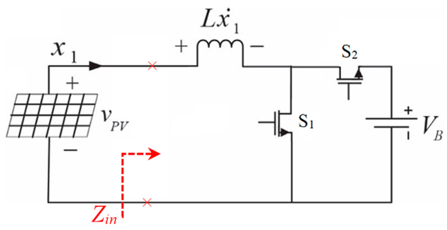
2.1. Input Impedance of the DC–DC Boost Converter (Zin)
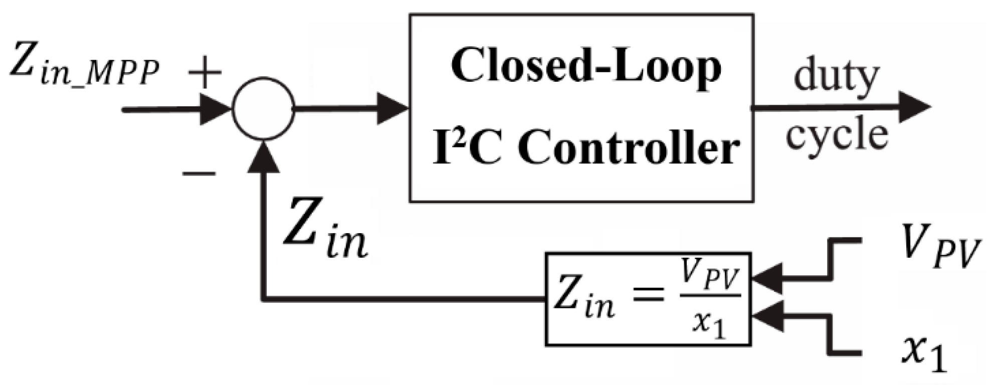
Considering the circuit depicted in Figure 1, the input impedance (Zin) of the DC–DC boost converter can be defined as follows:
Z i n = V P V x 1
where V P V and x 1 are the output voltage and current of the PV generator, respectively. For steady-state operation of the boost converter, the converter voltage gain can be expressed as follows:
A v = V o V i n = V B V P V = 1 1 d
where V B is the battery voltage, and d is the duty cycle of the boost converter. From this, the PV voltage can be expressed as follows:
V P V = ( 1 d ) V B
Similarly, the input current of the PV generator can be written as follows:
x 1 = I B 1 D
where I B is the battery current. Substituting this into (1), the equivalent input impedance of the converter can be calculated:
Z i n = V P V x 1 = 1 d 2 ( V B I B )
This shows that the input impedance of the converter can be directly controlled by adjusting the converter’s duty cycle. Furthermore, under steady-state conditions, if a fixed duty cycle is applied to the converter, the DC–DC boost converter can be modelled as a resistor.

2.2. I2C-MPPT Model

The operating point of the system, defined by the pair (VPV, x1), is determined by the intersection of the I–V curve of the PV generator and the load line, x 1 = 1 Z i n V P V , as discussed in the previous section (Equation (5)). Notably, the input impedance Zin can be controlled by adjusting the converter’s duty cycle. Therefore, the duty cycle and input impedance must be carefully tuned such that the operating point settles at the MPP, as shown in Figure 2.
At the MPP, the input impedance is given by the following:
Z i n _ M P P = V P V x 1 = V M P P I M P P
where V M P P and I M P P are the voltage and current at the MPP, respectively. If the values of V M P P and I M P P are known, Z i n _ M P P can be calculated and used as a reference for the closed-loop controller shown in Figure 3.
This control approach, referred to as I2C-MPPT, focuses on controlling the equivalent input impedance Z i n rather than relying on traditional voltage or current feedback signals within the closed-loop system. Figure 4 illustrates the Thevenin equivalent circuit representation of the input voltage source, which is used to model the renewable energy generator. In this configuration, the open-circuit voltage ( V O C = V S ) and internal resistance ( R S ) are considered uncertain parameters, reflecting the practical variability of real-world energy sources such as PV and thermoelectric generators. This abstraction enables the use of an equivalent input impedance matching approach, as the MPPT problem is reframed through aligning the converter’s input impedance ( Z i n ) with the source’s internal impedance to achieve maximum power transfer.

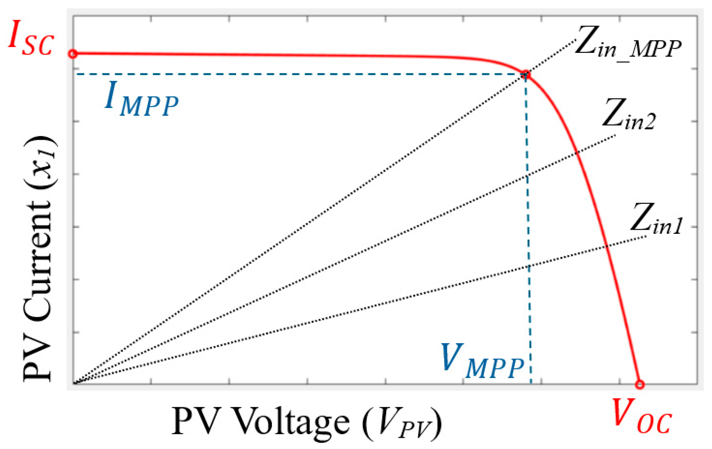
2.3. Reference Signal Estimation

To estimate the reference signal Z i n _ M P P for the controller, we leverage the improved fractional open-circuit voltage ( V O C ) and short-circuit current ( I S C ) methods, as outlined in recent literature [20]. According to Equation (6), the reference signal requires the values of V M P P and I M P P in PV applications. These values can be approximated as V M P P = K 1 V O C and I M P P = K 2 I S C where K 1 and K 2 are constants that relate the open-circuit voltage and short-circuit current to the MPP values. These constants K 1 and K 2 are typically derived from empirical measurements. Conventional fractional open-circuit voltage methods, while simple and cost-effective, typically struggle under partial shading conditions where multiple local peaks appear in the power-voltage characteristics. However, recent advancements—such as hybrid techniques combining fractional open-circuit voltage with optimisation algorithms [20]—have significantly improved the ability of these methods to track the global maximum power point. These enhancements offer higher tracking efficiency, faster response, and better performance in nonuniform irradiance scenarios. A detailed analysis of such advanced estimation techniques, however, falls beyond the scope of this research.
To estimate MPP values, V O C and I S C must be obtained from the synchronous DC–DC boost converter system. As shown in Figure 1, when both switches S1 and S2 are turned off, the output voltage of the PV system equals the open-circuit voltage V O C . For measuring the short-circuit current, when S1 is on and S2 is off, and after the system response has settled, the inductor behaves as a short circuit, allowing the short-circuit current I S C to be measured. These measurements of V O C and I S C , in conjunction with the fractional open-circuit and short-circuit methods, enable the estimation of Z i n _ M P P .

3. System Modelling and I2C-MPPT Design

In this section, the system modelling and I2C-MPPT closed-loop controller design for renewable generators is presented. Considering the proposed approach, the equivalent input impedance of the converter is controlled to match the equivalent internal impedance of the renewable generator. Consequently, the renewable generator can be represented using the Thevenin equivalent circuit, consisting of a voltage source in series with a resistor. Notably, their values depend on the operating point and characteristics of the renewable generator. For example, in thermoelectric generators and piezoelectric generators, the open-circuit voltage and internal resistance remain approximately constant across a wide range of operations. However, for PV generators, these values are highly dependent on the operating point. At a specific operating point, the PV generator can still be modelled using the same approach. From a controller design perspective, the values of open-circuit voltage and internal resistance are uncertain. Hence, modelling the input voltage source as a Thevenin circuit is an acceptable assumption if the model parameters are treated as uncertain values.

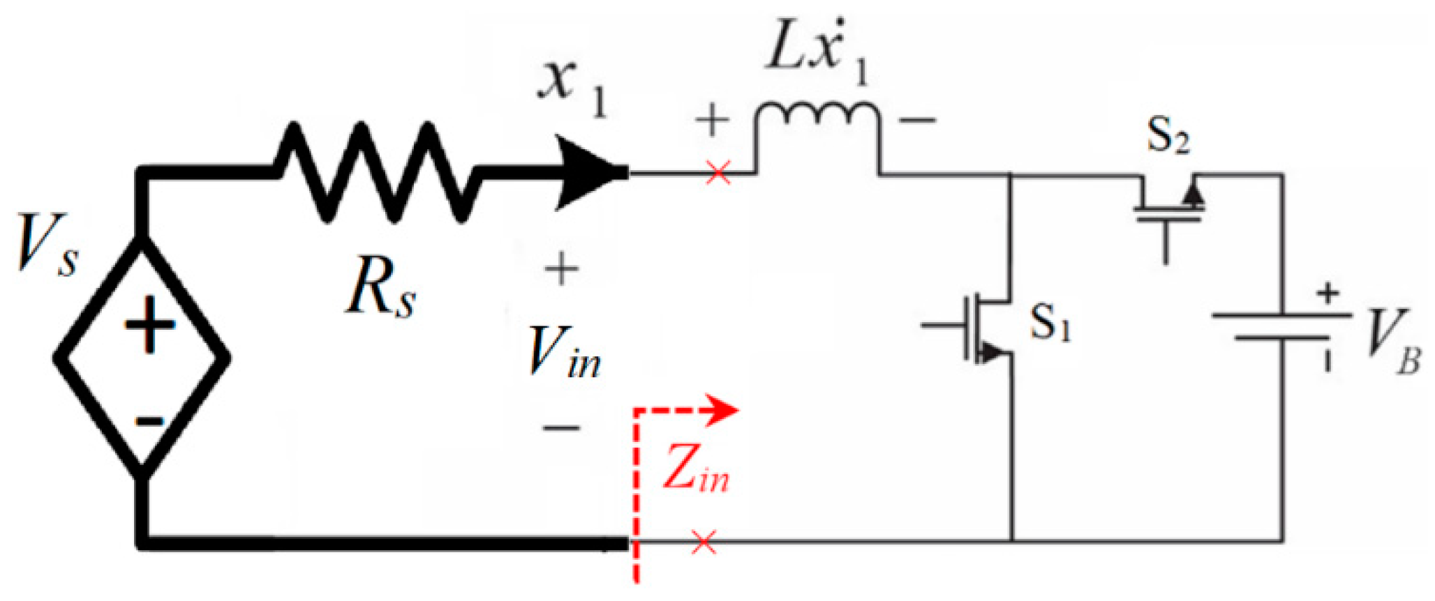
3.1. System Modelling

The system model assumes that the converter operates at a sufficiently high switching frequency to ensure Continuous Conduction Mode (CCM). Notably, with Discontinuous Conduction Mode (DCM), the input current ripple becomes significant, causing the operating point of the renewable generator to fluctuate widely around the MPP during steady-state operation. This fluctuation adversely affects system performance. Consequently, CCM operation is preferred for MPPT applications. Considering the switching states of the converter in CCM is discussed below.

3.1.1. Switching State 1 (S1: ON, S2: OFF)

In this state, the load (battery) is disconnected from the input source. Assuming the inductor current as the state variable and ideal switch operation (short circuit when ON and open circuit when OFF), the time derivative of the state variable can be expressed as follows:
x 1 ˙ = R S L x 1 + V S L

3.1.2. Switching State 2 (S1: OFF, S2: ON)

In this state, the energy stored in the inductor during the previous mode is transferred to the load battery. The time derivative of the state variable in this mode is given by the following:
x 1 ˙ = R S L x 1 + V S L V B L
By combining these two equations and applying an averaged state-space model, the system dynamics can be expressed as follows:
x 1 ˙ = R S L x 1 + V S L 1 d V B L
where d represents the duty cycle. This modelling approach provides a foundation for analysing and designing the control systems.

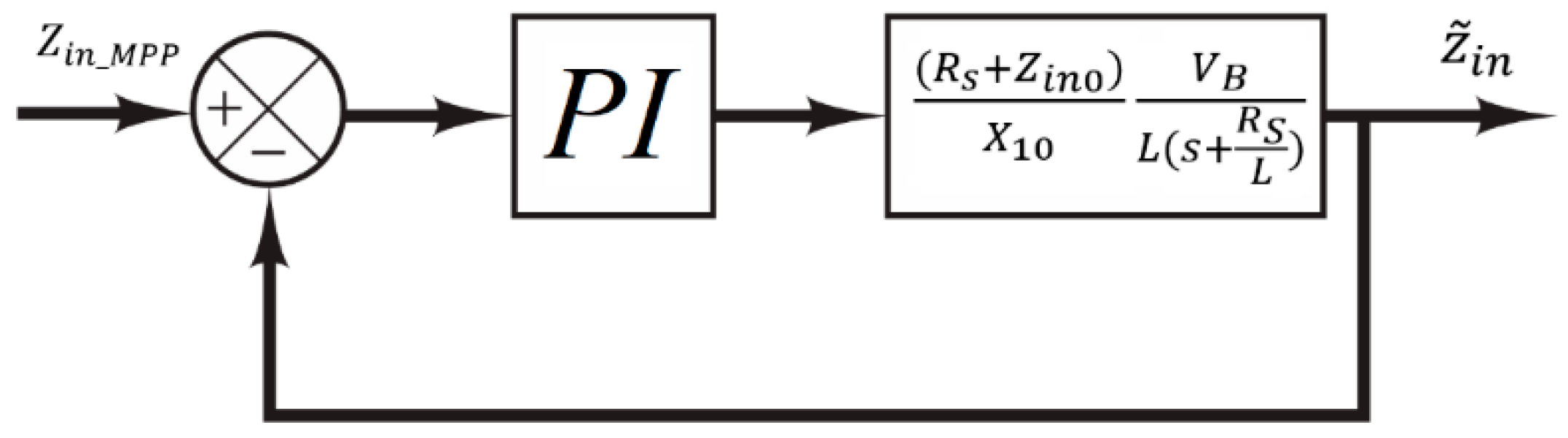
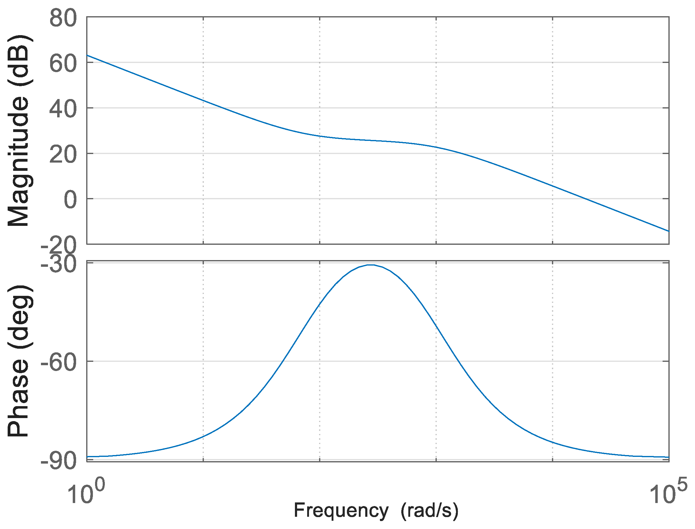
3.2. Model Linearisation and PI Control

From the perspective of controller design, the input variable is defined as u = 1 d , and the output is defined as z i n = V S R s x 1 x 1 . Consequently, the system transfer function is expressed as T F = z i n u = x 1 u × z i n x 1 . Considering the system nonlinearity and analysing it in small signal terms, small perturbations around the steady-state values are introduced:
x 1 = X 10 + x ~ 1
u = U 0 + u ~
z i n = Z i n 0 + z ~ i n
where X 10 , u 0 , and z i n 0 are steady-state values and x ~ 1 , u ~ , and z ~ i n are small-signal variables.
Substituting (10) and (11) into the original state-space equation in (9) yields the following:
x ~ 1 ˙ + X ˙ 10 = R S L ( X 10 + x ~ 1 ) + V S L ( u 0 + u ~ ) V B L
Separating the DC and ac terms in (11), and assuming X ˙ 10 = 0 , as the time derivative of the DC component is zero, we obtain the following:
X ˙ 10 = R S L X 10 + V S L V B L u 0 = 0
x ~ 1 ˙ = R S L x ~ 1 V B L u ~
Hence, the first term of the transfer function x ~ 1 u ~ can be expressed in the Laplace domain as follows:
x ~ 1 u ~ = V B L ( s + R S L )
Then, we replace (10) and (12), into z i n = V S R s x 1 x 1 :
Z i n 0 + z ~ i n = V S R s ( X 10 + x ~ 1 ) X 10 + x ~ 1
Equation (17) can be written as follows:
Z i n 0 + z ~ i n X 10 + x ~ 1 = V S R s ( X 10 + x ~ 1 )
Simplifying further, we can obtain the following:
Z i n 0 X 10 + Z i n 0 x ~ 1 + z ~ i n X 10 + z ~ i n x ~ 1 = V S R s X 10 R s x ~ 1
Assuming z ~ i n x ~ 1 = 0 , the DC and ac components can be separated in (19) as follows:
Z i n 0 X 10 = V S R s X 10
From these equations, we can obtain the following:
Z i n 0 = V S R s X 10 X 10
Using (23), the second term of the transfer function, z ~ i n x ~ 1 , can be written as follows:
z ~ i n x ~ 1 = ( R s + Z i n 0 ) X 10
The system transfer function can be determined using (16) and (24) as follows:
z ~ i n u ~ = z ~ i n x ~ 1 × x ~ 1 u ~ = ( R s + Z i n 0 ) X 10 V B L ( s + R S L )
Based on (25), it is shown that the I2C-MPPT system can be approximated using a first-order transfer function. The closed-loop block diagram of the linear PI controller used to implement the I2C-MPPT system is illustrated in Figure 5.

3.3. Lyapunov-Based Adaptive Nonlinear I2C-MPPT Design

Considering the equation used for modelling the input impedance, z i n = V S R s x 1 x 1 , the I2C-MPPT system exhibits nonlinear behaviour. As a result, the linear controller depicted in Figure 5 is unable to guarantee the stability and robustness of the closed-loop system under significant variations in V S , R s , and V B . To address this limitation, this paper proposes a novel adaptive nonlinear controller. In the proposed design, all system parameters are treated as uncertain, and adaptive rules are derived based on the Lyapunov stability criteria to estimate and compensate for the variations in these uncertain parameters effectively.
To design the adaptive nonlinear controller, the error is defined as follows:
e = Z i n _ M P P Z i n = Z i n M P P V S R s x 1 x 1
where Z i n _ M P P is the reference value of input impedance. So, the error dynamic can be extracted:
e ˙ = V S x 1 2 x 1 ˙
Assuming u = 1 d as a control input and substituting (9) into (25), we can obtain the following:
e ˙ = R S L V S x 1 + V S 2 L x 1 2 + V B V S L x 1 2 u
Due to the uncertainty of the model parameters in (28), the dynamic of error can be rewritten as follows:
e ˙ = θ 1 y + θ 2 y 2 + θ 3 y 2 u
where the state variable is mapped using y = 1 x 1 . Also, the model’s uncertain parameters are introduced based on the following equations:
θ 1 = R S L V S
θ 2 = V S 2 L
θ 3 = V B V S L
Assuming θ ^ 1 , θ ^ 2 , and θ ^ 3 as estimations of the uncertain parameters, the time-derivative of error in (29) can be rewritten as follows:
e ˙ = [ θ ^ 1 y + ( θ 1 θ ^ 1 ) y ] + [ θ ^ 2 y 2 + ( θ 2 θ ^ 2 ) y 2 ] + [ θ ^ 3 y 2 u + ( θ 3 θ ^ 3 ) y 2 u ]
To develop the adaptive nonlinear controller, the Lyapunov function, V , the I2C-MPPT system is introduced below, where θ ~ i = θ i θ ^ i and ρ i > 0 , which is called the parameter estimation weight (for i = 1,2, and 3).
V = 0.5 e 2 + 0.5 ρ 1 θ ~ 1 2 + 0.5 ρ 2 θ ~ 2 2 + 0.5 ρ 3 θ ~ 3 2
The time derivative of the Lyapunov function is as follows:
V ˙ = e e ˙ + ρ 1 θ ~ 1 θ ~ 1 ˙ + ρ 2 θ ~ 2 θ ~ 2 ˙ + ρ 3 θ ~ 3 θ ~ 3 ˙
Assuming θ ~ 1 ˙ = θ ^ 1 ˙ , θ ~ 2 ˙ = θ ^ 2 ˙ , and θ ~ 3 ˙ = θ ^ 3 ˙ , we can obtain the following:
V ˙ = e e ˙ ρ 1 θ ~ 1 θ ^ 1 ˙ ρ 2 θ ~ 2 θ ^ 2 ˙ ρ 3 θ ~ 3 θ ^ 3 ˙
Substituting e ˙ from (33) into (36), we can obtain the following:
V ˙ = e θ ^ 1 y + θ ^ 2 y 2 + θ ^ 3 y 2 u + ρ 1 θ ~ 1 θ ^ 1 ˙ + ρ 1 1 e y + ρ 2 θ ~ 2 θ ^ 2 ˙ + ρ 2 1 e y 2 + ρ 3 θ ~ 3 θ ^ 3 ˙ + ρ 3 1 e y 2 u
We assume the following:
θ ^ 1 y + θ ^ 2 y 2 + θ ^ 3 y 2 u = k e
and
θ ^ 1 ˙ + ρ 1 1 e y = 0
θ ^ 2 ˙ + ρ 2 1 e y 2 = 0
θ ^ 3 ˙ + ρ 3 1 e y 2 u = 0
which means that the time-derivate of the Lyapunov function in (37) will reduce to V ˙ = k e 2 which is a semi-definite negative function if k > 0 . Hence, those assumptions in (38)–(41) result in the asymptotic stability of the closed-loop system.
The nonlinear control law can be formulated based on (40):
u = 1 θ ^ 3 y 2 ( k e θ ^ 2 y 2 θ ^ 1 y )
Furthermore, the estimation rules for the uncertain parameters in (30)–(32) can be extracted using (39)–(41):
θ ^ 1 ˙ = ρ 1 1 e y
θ ^ 2 ˙ = ρ 2 1 e y 2
θ ^ 3 ˙ = ρ 3 1 e y 2 u

4. Simulation and Experimental Results

To investigate the performance of the proposed adaptive nonlinear I2C-MPPT approach against parameter variations such as open-circuit voltage (VS) and internal resistance (RS), the power circuit shown in Figure 4 is implemented. The system is validated through both simulations and experimental tests, with the nominal parameter values for both cases specified in Table 1.
The switching frequency (fS) is selected to ensure the CCM operation of the converter across the entire operating range.

4.1. Simulation Results

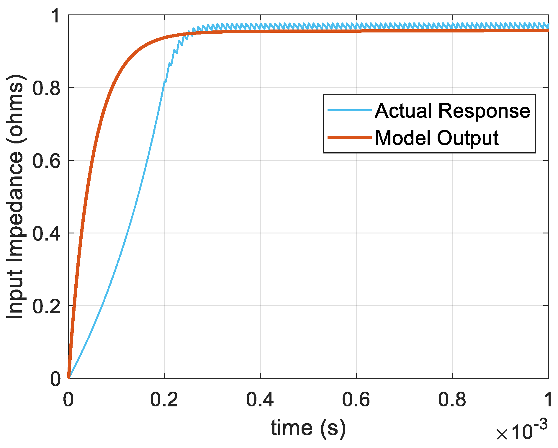
  • Test 1: Evaluation of the Linearised Model
The linearised model for the I2C-MPPT is evaluated by comparing the closed-loop system’s output shown in Figure 5 with the implemented actual closed-loop system using a PI controller. The comparison results, shown in Figure 6, indicate that the developed linearised model (in Equation (25)) accurately tracks the actual response obtained from the MATLAB simulations. This validates the correctness of the linearised model for the I2C-MPPT approach.
For all simulations presented for the linear controller, the proportional and integral gains were set to Kp = 4 and Ki = 300, respectively. It is noted that, due to the first-order linear approximation in (25), the system’s phase margin is not sensitive to changes in Kp and Ki. The Bode plot of the linearised model, shown in Figure 7, demonstrates a phase margin of approximately 92.8°, confirming system stability for the selected gains.
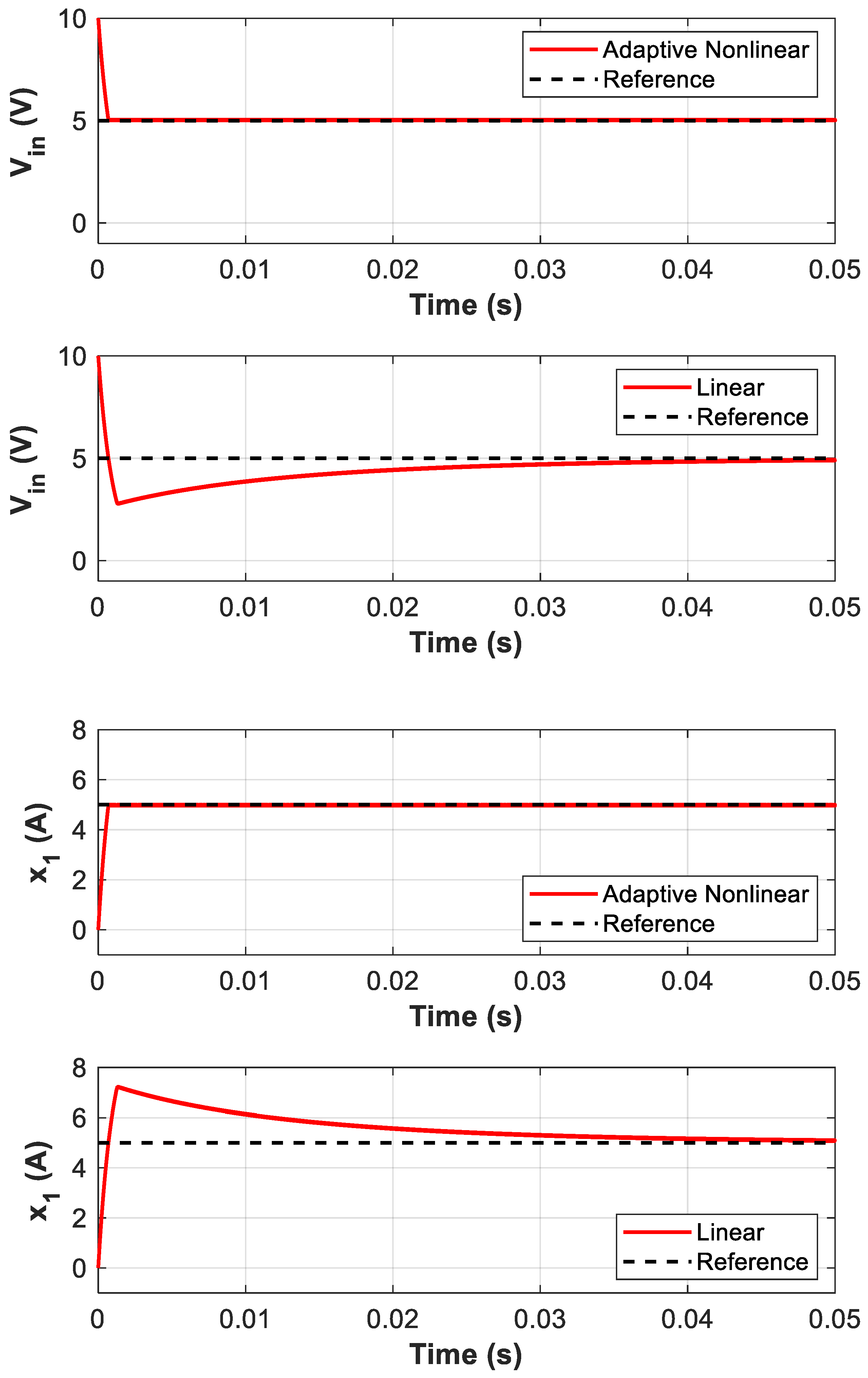
  • Test 2: Comparison of Linear and Adaptive Nonlinear Controllers
The response of the proposed adaptive nonlinear controller is compared with the linear controller. Figure 8 presents the converter’s input voltage (Vin) and current (x1) responses relative to their reference values for both linear and nonlinear controllers. Given an open-circuit voltage of VS = 10 V, the reference values for the Vin and current x1 are as follows:
V i n r e f = V S 2 = 5   V
x 1 r e f = V S R S + Z i n = V S 2 R S = 5   A
Both controllers achieve zero steady-state error, ensuring that the converter operates at the MPP with an input impedance matching the reference value. However, the proposed adaptive nonlinear controller exhibits significantly faster transient response, demonstrating superior performance during dynamic conditions.
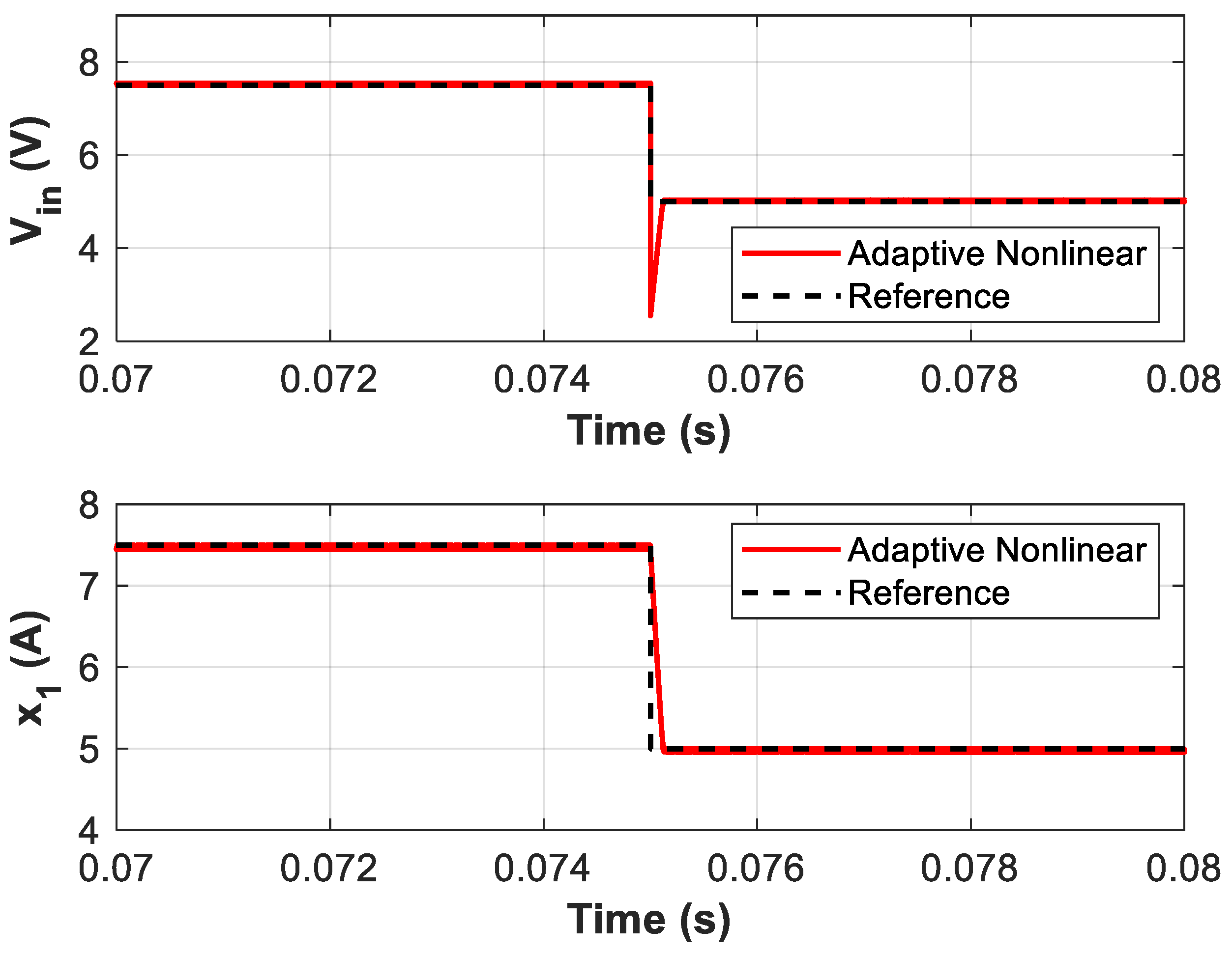
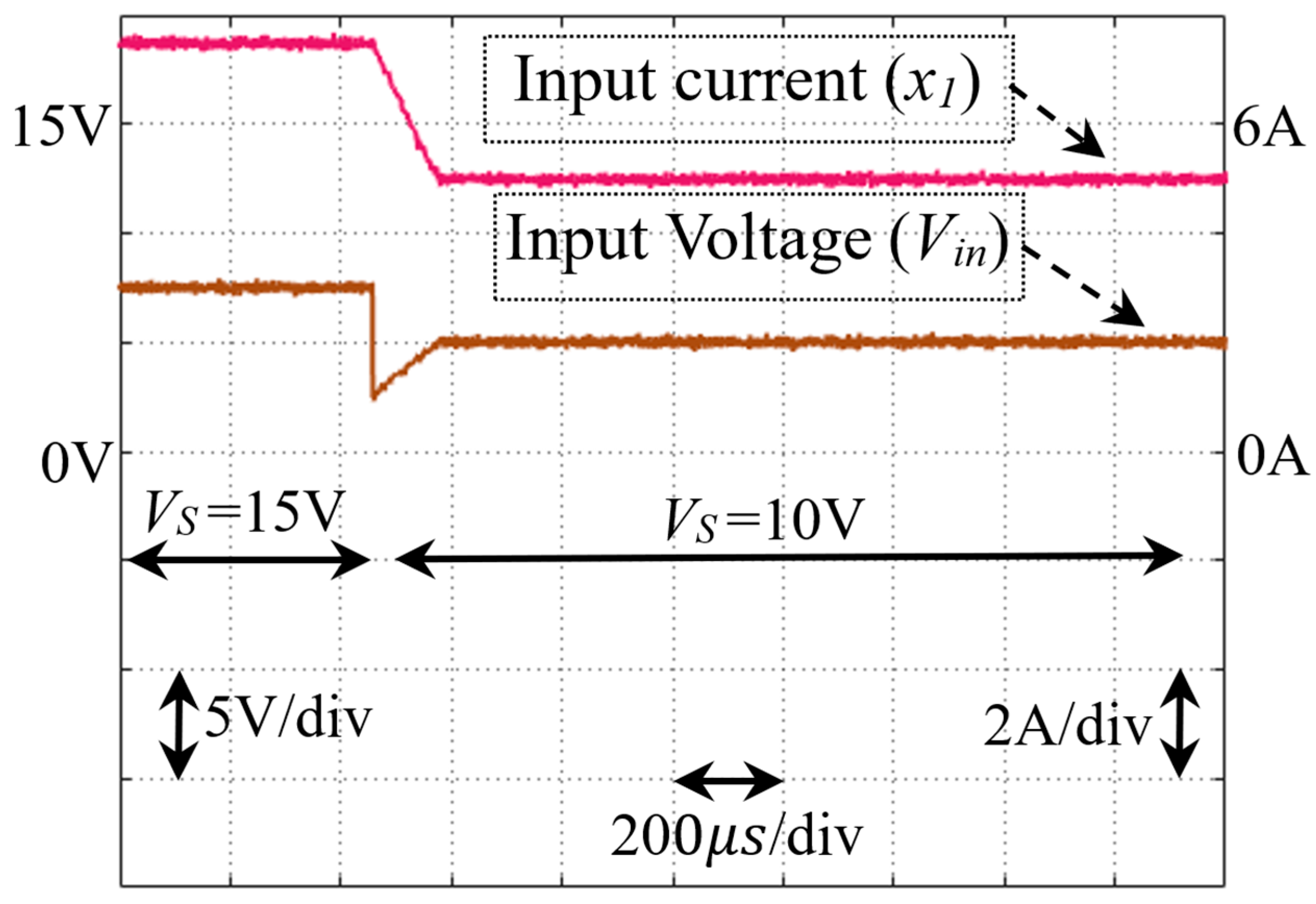
  • Test 3: Response to Open-Circuit Voltage Changes
The robustness of the adaptive nonlinear controller against changes in VS is evaluated in this test. Figure 9 shows the system’s response to a step change in VS from 15 V to 10 V at t = 0.075 s. According to the MPT theorem, V i n r e f = V S 2 changes from 7.5 V to 5 V and x 1 r e f = V S R S + Z i n = V S 2 R S changes from 7.5 A to 5 A. The simulation results confirm that the adaptive nonlinear controller remains stable and robust, successfully tracking the new reference values.
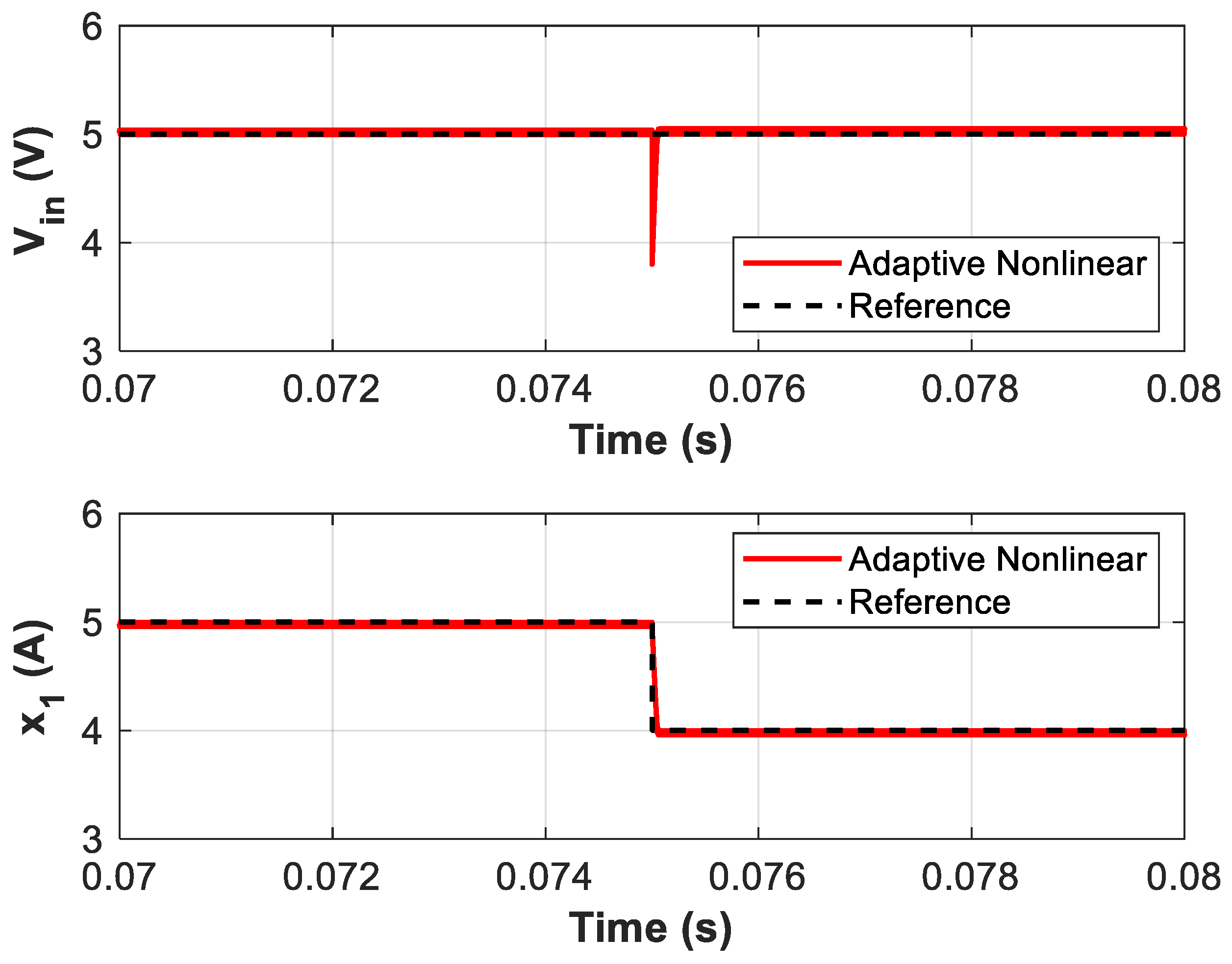
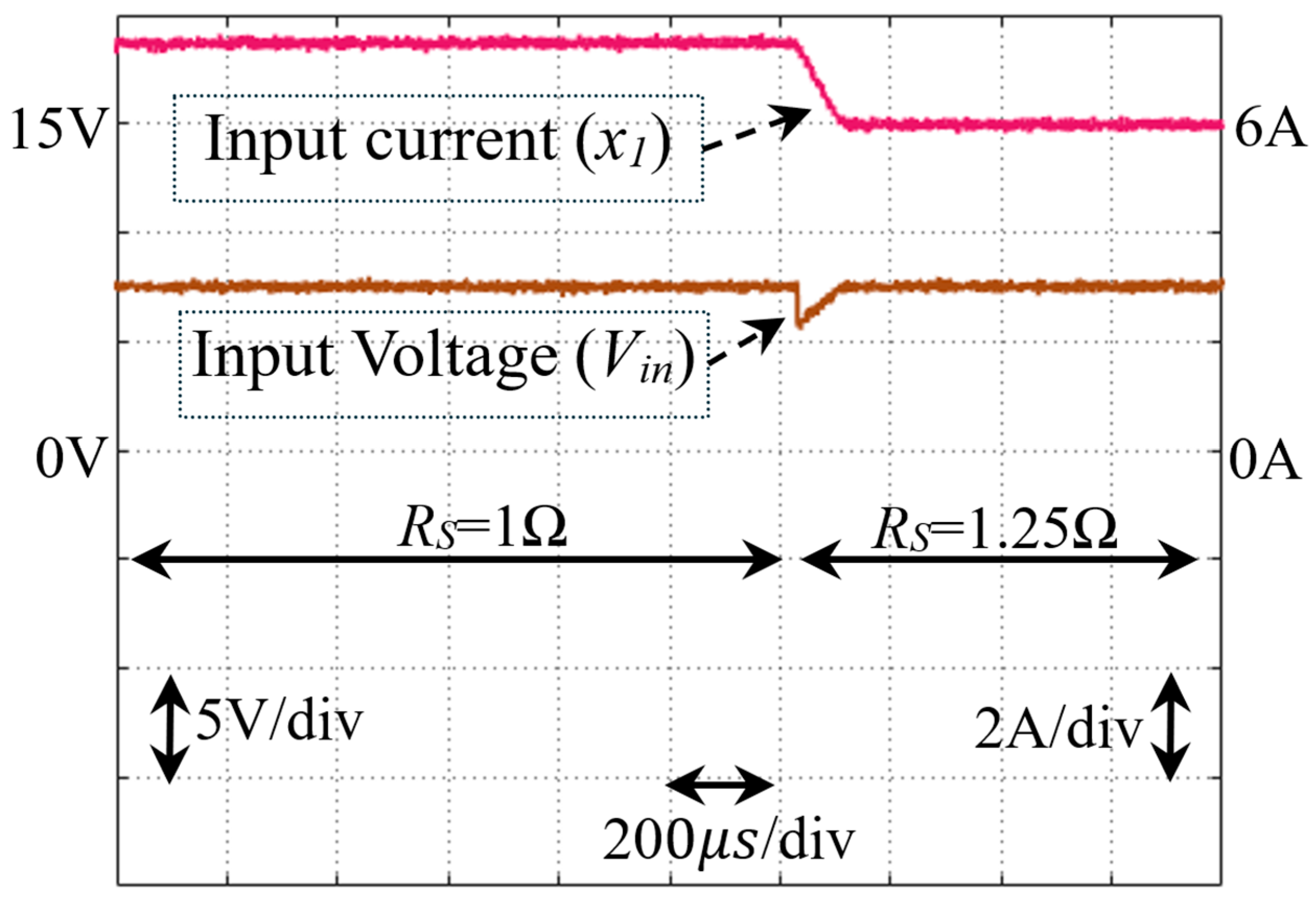
  • Test 4: Response to Internal Resistance Changes
The system’s response to a step change in RS from 1 Ω to 1.25 Ω is evaluated in this test. Figure 10 illustrates the simulation results. The input voltage reference value for this test is V i n r e f = V S 2 = 5 V . Also, x 1 r e f = V S R S + Z i n = V S 2 R S changes from 5 A to 4 A. The adaptive nonlinear controller successfully maintains stable operation, tracking the desired references despite changes in RS.
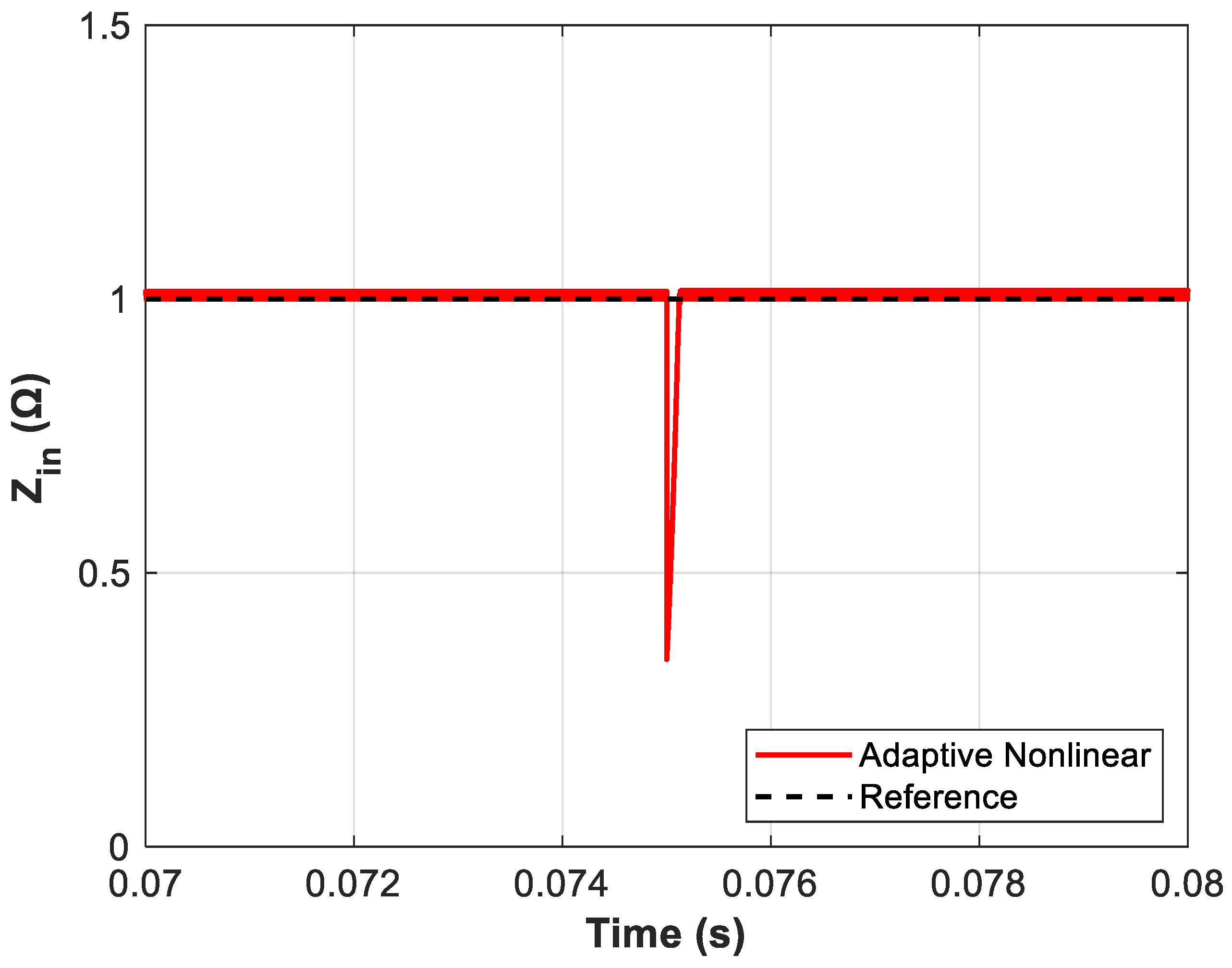
  • Test 5: Input Impedance Variation
Finally, the variation in the equivalent input impedance (Zin) with respect to the VS changes is analysed. At MPP, Zin_ref = Zin-MPP matches the internal resistance (RS). Figure 11 demonstrates that, despite the step changes in VS from 15 V to 10 V, the adaptive nonlinear controller accurately tracks the fixed reference value of Zin_ref = Zin-MPP = RS = 1 Ω. This highlights the controller’s robustness and precision in ensuring optimal system operation.

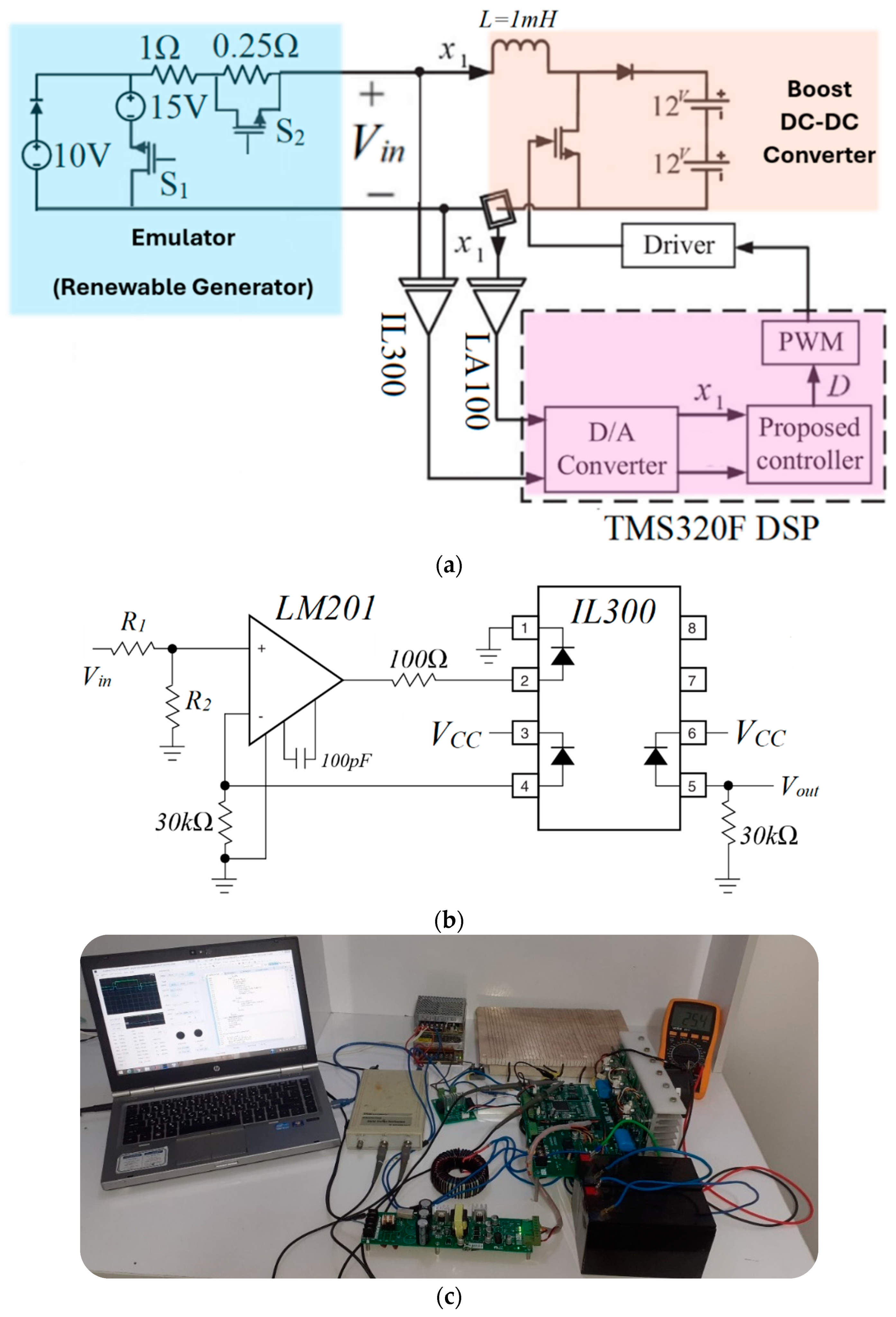
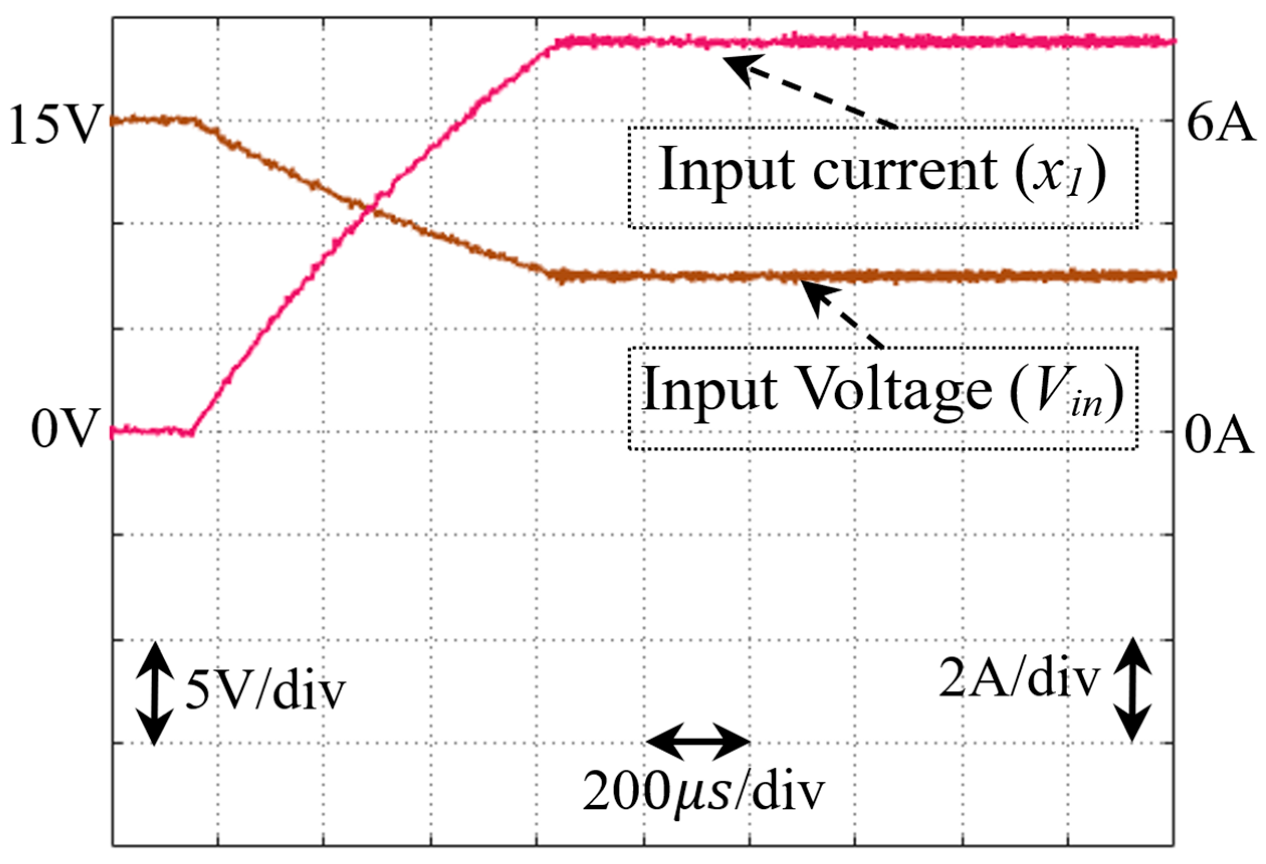
4.2. Experimental Results

The practical implementation of the proposed adaptive nonlinear I2C approach is illustrated in Figure 12a. To evaluate the controller’s dynamic response under parameter uncertainties, an emulator is employed, which can introduce step variations in both the open-circuit voltage and internal resistance by triggering switches S1 and S2, respectively. This setup enables a worst-case scenario evaluation, where the controller must adapt to sudden changes in these uncertain parameters.
To accurately measure the feedback signals, isolated sensors are integrated into the system for input voltage and current measurements, as shown in Figure 12a. The IL300 DC input-photodiode output-optocoupler from Vishay Intertechnology is utilised for voltage sensing, while the LA100 current sensor from the LEM LA series is employed for input current measurement. The controller is implemented on a TMS320F DSP platform from Texas Instruments, where the analogue feedback signals are digitised using internal A/D converters. The control law and parameter estimation Equations (42)–(45) are processed in real time within the DSP, and the computed duty cycle is translated into PWM switching signals.
To ensure proper isolation and fast gate control, a switch driver unit acts as the interface between the DSP and the power MOSFET. This driver is based on the CPL-316J-000E BiCMOS/DMOS output-optocoupler from Broadcom Inc., which provides current amplification while matching voltage levels. The power switching element used in both the converter and emulator circuits is the IRL540NPBF, a 36 A, 100 V N-channel MOSFET from Infineon Technologies AG. Notably, its internal antiparallel diode is also used as the boost converter diode. In this configuration, the gate and source terminals of the diode-connected MOSFET are short-circuited to ensure that the transistor remains off, allowing only the diode to conduct, as required by the circuit design.
All component values used in the experimental setup are identical to those defined for simulation, as summarised in Table 1. These include the converter’s inductance, switching frequency, and input/output conditions. The system load consists of two 12 V, 7 Ah sealed lead–acid batteries (BP7-12-T1 from B.B. Baterry) connected in series to provide a stable 24 V output. It should be noted that the experimental block diagram of the system is provided in Figure 12a. Additionally, Figure 12b presents a detailed schematic of the voltage monitoring board used to interface the converter’s input voltage with the DSP. The voltage sensing circuit, based on the IL300, operates in a unity-gain configuration. The actual voltage gain is determined by a resistor divider (R1 and R2) at the input stage, which scales the maximum expected converter voltage (24 V) to match the DSP’s analogue input limit (3 V). To meet this constraint, R2 is selected as 7 R1, ensuring the correct scaling factor. Further details on this voltage monitoring board design are based on the work presented in [21]. For current sensing, a 100 Ω shunt resistor (Rₘ) is used in conjunction with the LA100 sensor, as discussed in [22].
The experimental response of the converter is presented in Figure 13, Figure 14 and Figure 15. Figure 13 illustrates the system behaviour during startup. Initially, before the controller is activated, the input current remains at zero, and the open-circuit voltage (15 V) is observed at the input port. Upon activation, the input voltage drops and stabilises at half of the open-circuit voltage (7.5 V), confirming that the controller operates at the MPP according to the proposed I2C MPPT approach. At this condition, the input impedance matches the internal resistance (Rs = 1 Ω), resulting in an expected steady-state input current of x 1 = V S 2 R S = 15 2 = 7.5   A , which aligns with the measured waveform in Figure 13. Figure 14 presents the dynamic response of the controller to a step change in the open-circuit voltage, where VS is reduced from 15 V to 10 V. Consequently, the input voltage adjusts to 5 V, which remains at half of the new open-circuit voltage, validating that the controller maintains MPPT. The corresponding input current, calculated as x 1 = V S 2 R S = 10 2 = 5   A , is consistent with the experimental waveform in Figure 14. Lastly, Figure 15 illustrates the system’s response to a step change in the internal resistance from 1 Ω to 1.25 Ω. It is observed that, despite the resistance variation, the controller continuously adjusts the input voltage to sustain MPP operation as long as the open-circuit voltage remains constant.
It should be noted that the parameters for the adaptive nonlinear controller used in all simulations are K = 1 × 10⁶ and ρ i = 1 × 10⁻⁴.
Briefly, the simulation results validate the effectiveness of the proposed adaptive nonlinear I2C-MPPT approach. It demonstrates superior performance in tracking reference values, robustness against parameter variations, and stable operation under dynamic conditions, making it an excellent candidate for renewable energy systems.
Although the proposed controller has demonstrated robustness under variations in source voltage and internal resistance, broader environmental uncertainties such as irradiance fluctuations, temperature changes, and unpredictable load profiles remain an open challenge. To address this, future research could incorporate risk assessment tools, such as Conditional Value-at-Risk (CVaR) [23], to evaluate and manage worst-case performance scenarios in MPPT control. Such probabilistic measures would complement the deterministic framework presented here and offer a pathway for deploying the I2C-MPPT method in highly dynamic or grid-integrated renewable systems.
Furthermore, while the proposed MPPT strategy focuses on converter-level control for individual renewable sources, its structure lends itself to integration with system-level energy optimisation frameworks, such as those used in smart buildings or microgrids. By coordinating multiple converters, loads, and storage elements, the I2C-based MPPT approach could be extended to support multi-source operation, load coordination, and building-wide energy efficiency. Future research will explore how this controller can be embedded into hierarchical control architectures and aligned with higher-level objectives such as cost minimisation or energy-sharing strategies, as discussed in [24].

5. Conclusions

This paper presents a transformative approach to MPPT in renewable energy systems by introducing an adaptive nonlinear I2C strategy. Unlike conventional voltage- or current-based MPPT methods, the proposed approach formulates MPPT as an impedance matching problem based on the MPT theorem. By dynamically regulating the converter’s input impedance to match the internal impedance of the source, the I2C framework establishes a fundamental shift in control strategy, applicable to a wide range of renewable generators, including photovoltaic (PV) arrays, thermoelectric generators, and wind turbines.
A key innovation of this work lies in the development of a Lyapunov-based adaptive nonlinear controller that guarantees asymptotic stability while accounting for significant system uncertainties. The proposed controller eliminates the need for heuristic tuning or offline training, distinguishing it from traditional PI- and AI-based MPPT methods. Simulation and experimental validation confirm the controller’s robustness and superior performance: it achieves transient response times below 1 ms and maintains zero steady-state error across varying conditions. The approach successfully withstands extreme operating scenarios, such as 33% step changes in open-circuit voltage and 25% deviations in internal resistance, without compromising tracking accuracy.
Comparative analysis with conventional PI controllers highlights the advantages of the adaptive nonlinear I2C strategy in terms of faster rise time, improved settling time, and resilience to parameter fluctuations. The experimental results, obtained from a DSP-controlled prototype, further validate the real-time feasibility and practical applicability of the proposed control strategy. In addition to its theoretical rigor and practical robustness, the I2C framework provides a unified control paradigm that simplifies implementation while enhancing reliability. The physical grounding of the method in impedance matching principles enables broad applicability and consistent performance across diverse renewable energy applications. Future research will explore the integration of the proposed I2C strategy into hybrid and grid-forming power systems, expanding its potential to support next-generation distributed energy architectures.

Funding

This research was funded by University of Greenwich (grant number KE4 Impact-P13540).

Data Availability Statement

All data presented in this study were generated through PC-based simulations based on the detailed parameters provided in the Results section. No additional data were used or generated during the study.

Acknowledgments

The author gratefully acknowledges the support provided by the University of Greenwich through the Research Award (KE4 Impact Evaluator FES) under Project Code P13540. This work is part of the project titled “Maximising Energy Cost Savings with a Novel Multifunctional Controller for Grid-Connected Photovoltaic Systems”.

Conflicts of Interest

The author declare no conflict of interest.

References

  1. Mosetlhe, T.; Yusuff, A.; Ayodele, T.; Ogunjuyigbe, A. Sustainable Rural Electrification through Micro-Grids in Developing Nations—A Review of Recent Development. Energy Rep. 2025, 13, 1171–1177. [Google Scholar] [CrossRef]
  2. Kaplani, E. Design and Performance Considerations in Standalone PV Powered Telecommunication Systems. IEEE Lat. Am. Trans. 2012, 10, 1723–1729. [Google Scholar] [CrossRef]
  3. Saxena, A.; Aishwarya, B.; Badhoutiya, A.; Raj, V.H.; Gupta, M.; Khayoon, A.T. Designing a Resilient Microgrid for Disaster-Prone Areas Using Renewable Energy Sources. In Proceedings of the 2024 International Conference on Trends in Quantum Computing and Emerging Business Technologies, Pune, India, 22–23 March 2024; pp. 1–6. [Google Scholar]
  4. Rehman, A.U.; Alamoudi, Y.; Khalid, H.M.; Morchid, A.; Muyeen, S.M.; Abdelaziz, A.Y. Smart Agriculture Technology: An Integrated Framework of Renewable Energy Resources, IoT-Based Energy Management, and Precision Robotics. Clean. Energy Syst. 2024, 9, 100132. [Google Scholar] [CrossRef]
  5. Yang, O.; Xie, R.; Duan, J.; Wang, J. State-of-the-Art Review of MPPT Techniques for Hybrid PV-TEG Systems: Modeling, Methodologies, and Perspectives. Glob. Energy Interconnect. 2023, 6, 567–591. [Google Scholar] [CrossRef]
  6. Zhang, X.; Jia, J.; Zheng, L.; Yi, W.; Zhang, Z. Maximum Power Point Tracking Algorithms for Wind Power Generation System: Review, Comparison and Analysis. Energy Sci. Eng. 2023, 11, 430–444. [Google Scholar] [CrossRef]
  7. Shen, J.; Xia, Y.; Xia, H. ReL-SSHI Rectifier-Based Piezoelectric Energy Harvesting Circuit with MPPT Control Technique. Microelectron. J. 2022, 121, 105379. [Google Scholar] [CrossRef]
  8. Zhong, W.; Zhang, M.; Zhang, J.; Liu, J.; Yu, H. Constrained MPPT Strategy for Sustainable Wave Energy Converters with Magnetic Lead Screw. Sustainability 2024, 16, 4847. [Google Scholar] [CrossRef]
  9. Khadidja, S.; Mountassar, M.; M’hamed, B. Comparative Study of Incremental Conductance and Perturb & Observe MPPT Methods for Photovoltaic System. In Proceedings of the 2017 International Conference on Green Energy Conversion Systems (GECS), Hammamet, Tunisia, 23–25 March 2017; pp. 1–6. [Google Scholar]
  10. Mishra, J.; Das, S.; Kumar, D.; Pattnaik, M. Performance Comparison of P&O and INC MPPT Algorithm for a Stand-Alone PV System. In Proceedings of the 2019 Innovations in Power and Advanced Computing Technologies (i-PACT), Vellore, India, 22–23 March 2019; pp. 1–5. [Google Scholar]
  11. Li, Z.; Dewantoro, G.; Xiao, T.; Swain, A. A Comparative Analysis of Fuzzy Logic Control and Model Predictive Control in Photovoltaic Maximum Power Point Tracking. Electronics 2025, 14, 1009. [Google Scholar] [CrossRef]
  12. Bandara, A.; Ratnayake, K.; Dissanayake, R.; Udawatte, H.; Godaliyadda, R.; Ekanayake, P.; Ekanayake, J. LSTM-Based MPPT Algorithm for Efficient Energy Harvesting of a Solar PV System Under Different Operating Conditions. Electronics 2024, 13, 4875. [Google Scholar] [CrossRef]
  13. Zhu, W.; Li, P.; Yang, W.; Xie, C.; Li, H.; Yang, Y. Maximum Power Point Tracking Using a Multimode Hunter-Prey Optimization Algorithm for Gradually Varying Power in Centralized Thermoelectric Generation System. Energy Technol. 2025, 2402070. [Google Scholar] [CrossRef]
  14. Abdel-Rahim, O.; Wang, H. A New High Gain DC-DC Converter with Model-Predictive-Control-Based MPPT Technique for Photovoltaic Systems. CPSS Trans. Power Electron. Appl. 2020, 5, 191–200. [Google Scholar] [CrossRef]
  15. Ko, J.-S.; Chung, D.-H. The MPPT Control of PV System Using the Series-Connected PI Controller. In Proceedings of the 2016 16th International Conference on Control, Automation and Systems (ICCAS), Gyeongju, Republic of Korea, 16–19 October 2016; pp. 807–809. [Google Scholar]
  16. Siddula, S. Analysis of Fuzzy Logic Based MPPT Using Incremental Conductance Technique for PV Cell. In Proceedings of the 2020 International Conference on Smart Technologies in Computing, Electrical and Electronics (ICSTCEE), Bengaluru, India, 9–10 October 2020; pp. 180–185. [Google Scholar]
  17. Khelifi, B.; Zdiri, M.A.; Ben Salem, F. Machine Learning for Solar Power Systems—A Short Tour. In Proceedings of the 2021 12th International Renewable Energy Congress (IREC), Hammamet, Tunisia, 26–28 October 2021; pp. 1–6. [Google Scholar]
  18. Pradhan, R.; Subudhi, B. Double Integral Sliding Mode MPPT Control of a Photovoltaic System. IEEE Trans. Control Syst. Technol. 2016, 24, 285–292. [Google Scholar] [CrossRef]
  19. Salimi, M. Practical Implementation of the Lyapunov Based Nonlinear Controller in DC-DC Boost Converter for MPPT of the PV Systems. Sol. Energy 2018, 173, 246–255. [Google Scholar] [CrossRef]
  20. Hassan, A.; Bass, O.; Masoum, M.A.S. An Improved Genetic Algorithm Based Fractional Open Circuit Voltage MPPT for Solar PV Systems. Energy Rep. 2023, 9, 1535–1548. [Google Scholar] [CrossRef]
  21. Vishay Intertechnology. IL300 Linear Optocoupler—High Gain Stability, Wide Bandwidth. Available online: https://www.vishay.com (accessed on 22 April 2025).
  22. LEM International. LA 100-P Current Transducer Datasheet. Available online: https://www.lem.com (accessed on 22 April 2025).
  23. Zhai, X.; Li, Z.; Li, Z.; Xue, Y.; Chang, X.; Su, J.; Jin, X.; Wang, P.; Sun, H. Risk-Averse Energy Management for Integrated Electricity and Heat Systems Considering Building Heating Vertical Imbalance: An Asynchronous Decentralized Approach. Appl. Energy 2025, 383, 125271. [Google Scholar] [CrossRef]
  24. Zhang, H.; Liu, Y.; Wu, C.; Tan, Y.; Li, Z.; Zhang, D. A Stochastic Bi-Level Optimal Allocation Approach of Intelligent Buildings Considering Energy Storage Sharing Services. IEEE Trans. Consum. Electron. 2024, 70, 5142–5153. [Google Scholar] [CrossRef]
Figure 1. Equivalent input impedance (Zin) of the converter.
Electronics 14 01960 g001
Figure 2. I–V profile a typical PV generator and corresponding load lines. In the proposed I2C approach, adjusting the converter duty cycle alters the load line and equivalent input impedance (Zin), enabling the MPPT of the generator.
Electronics 14 01960 g002
Figure 3. Structure of the proposed I2C controller.
Electronics 14 01960 g003
Figure 4. Block diagram of the developed linear control system.
Electronics 14 01960 g004
Figure 5. Thevenin equivalent circuit representation of the input voltage source, with model parameters considered as uncertain.
Electronics 14 01960 g005
Figure 6. Comparison of the output of the linearised model, based on the system’s transfer function in Figure 5, with the actual response from the Simulink R2024b simulation. The results demonstrate the accuracy of the developed linear model for the I2C-MPPT.
Electronics 14 01960 g006
Figure 7. Bode plot of the linearised I2C-MPPT system, derived from the block diagram shown in Figure 5, illustrating the phase margin and stability of the system.
Electronics 14 01960 g007
Figure 8. Comparison of the converter input voltage (Vin) and current (x1) to their reference values for the proposed adaptive nonlinear controller and the linear controller during converter startup. Both controllers achieve steady-state operation at the MPP, but the adaptive nonlinear controller exhibits a significantly faster transient response, demonstrating superior dynamic performance.
Electronics 14 01960 g008
Figure 9. Response of the adaptive nonlinear controller to a step change in the open-circuit voltage (VS) from 15 V to 10 V at t = 0.075 s. The controller successfully adjusts the input voltage (Vin) and input current (x1) to their new reference values, maintaining stable operation and MPPT.
Electronics 14 01960 g009
Figure 10. Response of the adaptive backstepping controller to a step change in the internal resistance (RS) from 1 Ω to 1.25 Ω at t = 0.075 s. The controller effectively tracks the new reference values of the input voltage (Vin) and current (x1), maintaining stable and robust system operation.
Electronics 14 01960 g010
Figure 11. Variation in the equivalent input impedance (Zin) to step changes in open-circuit voltage (VS) from 15 V to 10 V. The adaptive nonlinear controller effectively tracks the reference impedance (Zin_ref = Zin-MPP = RS = 1 Ω), ensuring stable and optimal operation at MPP.
Electronics 14 01960 g011
Figure 12. Schematic of the experimental setup, including the emulator, power circuit, sensor connections, and controller implementation (a); detailed schematic of the voltage monitoring board based on the IL300 optocoupler used for input voltage sensing in the practical implementation (b); and experimental test rig illustrating the practical implementation of the proposed I2C-MPPT approach (c).
Electronics 14 01960 g012
Figure 13. Practical response of the converter during startup, demonstrating the controller’s ability to achieve MPP operation by stabilising the input voltage at half of the open-circuit voltage.
Electronics 14 01960 g013
Figure 14. Dynamic response of the proposed controller to a step change in open-circuit voltage (VS), confirming its ability to maintain MPPT under varying source conditions.
Electronics 14 01960 g014
Figure 15. System response to a step change in internal resistance (RS), illustrating the controller’s capability to adapt and sustain MPP operation despite resistance variations.
Electronics 14 01960 g015
Table 1. Nominal parameter values of the simulated system and experimental setup.
ParameterSymbolValue
Open-Circuit VoltageVS10 V
Internal ResistanceRS1 Ω
Load VoltageVB24 V
Converter InductanceL1 mH
Switching FrequencyfS100 kHz
Disclaimer/Publisher’s Note: The statements, opinions and data contained in all publications are solely those of the individual author(s) and contributor(s) and not of MDPI and/or the editor(s). MDPI and/or the editor(s) disclaim responsibility for any injury to people or property resulting from any ideas, methods, instructions or products referred to in the content.

