Abstract
Complex-valued neural networks have emerged as an effective instrument in image reconstruction, exhibiting significant advancements compared to conventional techniques. This study introduces an innovative methodology to tackle the difficulties related to image reconstruction within medical microwave imaging. Initially, in the estimation phase, the proposed methodology integrates the Born iterative method with quadratic programming. Subsequently, in the refinement stage, the study explores the application of complex-valued neural networks to enhance the quality of reconstructions. The research emphasizes distinct complex-valued neural network architectures, namely, CV-UNET, CV-CNN, CV-MLP, and their corresponding performances. CV-UNET stands out as the best architecture, surpassing conventional methods and the other complex-valued neural networks variants. The complex-valued neural network improves the fidelity of reconstructions and simplifies the procedure by obviating the need for multiple training steps, a common prerequisite in real-valued neural networks.
1. Introduction
Microwave imaging is a non-invasive medical imaging technique grounded in the principles of electromagnetic scattering, where microwave signals are utilized to probe the dielectric properties of biological tissues. One of the fundamental challenges in microwave imaging is solving the inverse scattering problem (ISP) [1], which involves determining the interior characteristics of biological tissues based on the measurements of scattered microwave signals. This problem is inherently difficult to solve because it is ill posed and non-linear [2], resulting in several local minima when approached as an optimization problem. Several techniques have been employed to address the ISP. These include iterative optimization methods incorporating regularizations, such as the Born iterative method (BIM) [3], the distorted Born iterative method (DBIM) [4], the contrast source inversion (CSI) method [5], and the subspace optimization method (SOM) [6]. The parameters of unknown scatterers are reconstructed by iteratively minimizing an objective function, which measures the difference between computed and measured data. One significant limitation of these iterative approaches is their time-consuming nature, rendering them unsuitable for real-time reconstruction. The integration of machine learning (ML) and especially deep learning (DL) has emerged as a notable advancement in recent years, transforming the approach to addressing the ISP in microwave imaging. ML algorithms can learn and detect intricate patterns that may be challenging to capture just through analytical methods by employing comprehensive datasets comprising measurements of electromagnetic scattering [7]. Several research studies have been conducted to examine the application of deep neural networks (DNNs) in this context. One such method involves utilizing a convolutional neural network (CNN) architecture to solve ISPs based on learning the spatial noise of the radiation operator [8]. Another methodology involves the utilization of an end-to-end DL framework for quantitative microwave breast imaging in real-time scenarios [9]. In [10], a U-NET-based deep neural network was proposed for addressing nonlinear electromagnetic ISP. Recent studies have demonstrated that neural network (NN)-based [11,12] and DNN-based strategies exhibit superior performance compared to traditional image reconstruction methods, as evidenced by the enhanced image quality and decreased processing costs [13,14]. In electromagnetic waves and microwave imaging, the utilization of traditional neural networks is often constrained due to their dependence on real-valued input. This limitation arises from the prevalence of complex-valued data in these applications. complex-valued neural networks (CVNNs) extend the capabilities of conventional neural networks that enable the processing of complex numbers, which is particularly important in accurately capturing the phase and magnitude of electromagnetic waves. Furthermore, incorporating phase rotation and amplitude attenuation capabilities within complex numbers, diminishes the level of freedom present within the neural network [15]. In addition, studies have demonstrated that CVNNs have a reduced impact on the presence of singular points compared to real-valued neural networks (RVNNs) during the training process [16]. Numerous studies have examined the application of CVNNs in addressing the ISP within the domain of microwave imaging. The research paper [17] introduced a sophisticated, complex convolutional neural network model named DeepNIS, designed to address the challenges of nonlinear electromagnetic inverse scattering. A complex-valued convolutional neural network utilizing an autoencoder was introduced by [18] as a solution to the electromagnetic ISP, which addresses the challenge of training the network for inverse reconstruction by employing a two-stage training procedure. The authors of [19] employed a CNN with complex-valued inputs for the initial estimation stage, and then a residual network was used for the refining phase. In [20], a complex-valued DNN was proposed, which operates on complex-valued data, to address the problem of nonlinear electromagnetic inverse scattering. The authors in [21] introduced one of the first end-to-end deep learning frameworks designed to operate entirely in the complex domain. Their work demonstrated that complex-valued convolutional networks can outperform their real-valued counterparts in tasks involving complex data structures, such as signal classification and image recognition. The work presented in [22] explores the theoretical and practical benefits of complex-valued neural networks, emphasizing their ability to handle phase-dependent information and preserve signal integrity. It details how CVNNs naturally fit problems involving electromagnetic waves and oscillatory behavior and discusses activation functions, backpropagation, and learning dynamics in the complex plane. Recent studies have highlighted the potential of adaptable activation functions in complex-valued neural networks (CVNNs). In particular, the work in [23] proposes non-parametric kernel activation functions (KAFs) designed specifically for the complex domain. The authors introduce two configurations: a split-KAF, where the real and imaginary parts are processed separately using kernel-based expansions, and a fully complex KAF leveraging complex reproducing kernel Hilbert spaces. Their experiments demonstrate that these flexible activations outperform traditional fixed or parametric functions in tasks such as channel equalization, wind prediction, and image classification. Additionally, CVNNs have shown significant promise in radar signal processing tasks, particularly for applications involving polarimetric synthetic aperture radar (PolSAR) data. In [24], a comprehensive study compares CVNNs with their real-valued counterparts (RVNNs) in terms of classification and segmentation performance on complex-valued radar datasets. These findings reinforce the growing relevance of complex-valued architectures in wave-based imaging and motivate their extension to biomedical microwave imaging, where fully exploiting the complex structure of the data is critical for improving reconstruction quality.
Conversely, this study introduces a comprehensive method that addresses the substantial issues related to ISP in medical imaging, as illustrated in Figure 1. The proposed methodology integrates the Born iterative method (BIM) with quadratic programming for the initial estimation phase. Then, in the subsequent refinement stage, we develop and evaluate three complex-valued neural networks (CVNNs) specifically designed to handle complex value inputs and produce complex value outputs. The main contributions of this study are as follows: (i) we integrate the quadratic Born iterative method (BIM) with complex-valued neural networks (CVNNs) to enhance the reconstruction of dielectric profiles in microwave imaging; (ii) we implement and compare three CVNN architectures demonstrating their respective efficiency in processing complex-valued input data derived from BIM outputs; (iii) we perform a comprehensive quantitative evaluation against real-valued neural networks (RVNNs) across various metrics; and (iv) we examine the computational efficiency and memory utilization of each model to evaluate their practical viability. In general, these contributions aim to illustrate the advantages of employing CVNNs in electromagnetic inverse problems and to provide a solid foundation for future investigations in complex-valued deep learning within biomedical imaging.
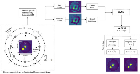
Figure 1.
Electromagnetic configuration scheme.
This paper is organized as follows. Section 2 presents the problem formulation for microwave image reconstruction in the complex domain. Section 3 describes the architecture of each proposed complex-valued neural network (CVNN). Section 4 details the construction of CVNNs. Section 5 provides numerical results and comparative evaluations against real-valued neural networks. Finally, Section 6 concludes the paper and outlines potential directions for future research.
2. Problem Formulation
The measurement setup illustrated in Figure 1 represents a 2-D Transverse Magnetic (TM) measurement configuration. The area of focus, commonly known as the Domain of Interest (DOI), is the specific location where our object of interest () is located. The is subjected to a series of incident waves (), denoted as . Here, n denotes the index of nth illumination, while N represents the total number of transmitters or line sources. For each illumination event, a collection of M receivers is uniformly distributed throughout the observation domain S. The receivers play a vital role in capturing the scattered electric fields produced by the target. The integral equation of the electric field can describe the total field in and the scattered field in the domain S. These fields can be represented using a discretized form as follows:
where and are the vectors of the total and incident fields inside , respectively; is a matrix that represents the 2-D Green’s function [2] within the .
The induced current is defined as , where is a diagonal matrix; the nth diagonal element can be denoted as . Furthermore, and refer to the dielectric permittivity and conductivity of the target, respectively; the dielectric constant of the background is denoted as , and the operating angular frequency is represented by . This formulation assumes a time-harmonic dependence of and explicitly includes the background conductivity term to provide a general representation of the complex contrast in the medium.
The representation of the scattered field in its discretized form is as follows:
where denotes the scattered electric field at the position inside the measurement domain S; (with and ) is derived by the process of discretizing Green’s function for ; the contrast value at is denoted as , and represents the total electric field at location .
The objective of the forward problem is to solve (1) for , given the value of , subsequently (2) for . The inverse problem refers to the estimation of contrast , specifically relative permittivity and conductivity , based on scattered fields , while considering incident fields . Since the induced sources J are unknown, they must be estimated simultaneously with .
Quadratic Born Iterative Method
The proposed approach for addressing this problem involves the utilization of Born iterative method (BIM) with a quadratic programming approach. The nonlinear inverse problem is formulated as the minimization of a cost function that exhibits the following structure:
The residual term refers to quantifying the discrepancy between the measured scattered electric field and the predicted scattered electric field, indicating how well the estimated object approximates the actual object. Minimizing the sum of the estimation errors can be reformulated as minimizing the slack variables represented by . Then, the is introduced to the scattered field formula as follows:
Incorporating slack variables enables the treatment of equality constraints in an integrated way within the context of quadratic programming (QP). The best solution to QP will guarantee the satisfaction of the constraints and the minimization of the slack variables, , which converge to their ideal value when the variables provide the most accurate approximation to the scattered field measurements (4). It is important to note that since the variables and are complex, the QP method, designed for problems involving real variables, requires decomposing variables and the constraint equations into their corresponding real and imaginary components.
3. Complex-Valued Neural Network (CVNN)
This section corresponds to the refinement stage of the initial estimate obtained with the quadratic BIM approach. In order to achieve this objective, we introduce three sophisticated CVNNs, specifically developed to tackle the difficulties arising from complex contrast values encountered in microwave imaging. Our investigation begins with a comprehensive assessment of a basic structure known as a complex-valued multilayer perceptron (CV-MLP). Subsequently, a complex-valued convolutional neural network (CV-CNN) will be examined. Finally, an analysis of a more intricate architecture, the complex-valued U-NET (CV-UNET), will be performed.
3.1. Architecture of CV-MLP
The CV-MLP model consists of a sequential neural network architecture incorporating multiple layers. The process begins with a layer, which accepts an input of dimensions 128 × 128 pixels and transforms it into a one-dimensional array with a size of 16,384. The flattened representation is subsequently fed into a sequence of layers. The initial three layers are configured with 64 units each, using activation function. This activation function involves the application of a rectified linear unit (ReLU) activation function to both the real and imaginary components of the complex numbers independently. The last-layer consists of 128 units. The dimensions of the output layer are equivalent to the flattened input, which consists of 16,384 units. The model is compiled using the Mean Squared Error (MSE) loss function and the Adam optimizer. The model possesses 6,349,312 trainable parameters and has been specifically performed to perform a regression task on complex data. The architecture of CV-MLP is illustrated in Figure 2.
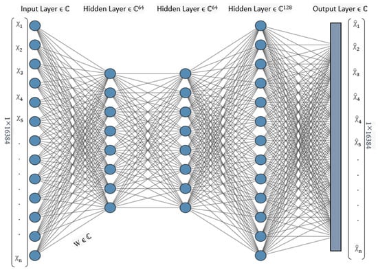
Figure 2.
Complex-valued multilayer percetron (CV-MLP) network architecture.
3.2. Architecture of CV-CNN
The architecture of the complex-valued convolutional neural network (CV-CNN) is depicted in Figure 3. The fundamental architecture resembles CNNs designed for regression tasks involving real-valued data [25]. The present model is a deep neural network explicitly engineered to process complex data. The architecture comprises an initial input layer, succeeded by three encoder blocks. Each encoder block comprises a convolutional layer with complex-valued weights and a max pooling layer that operates on complex values. The convolutional layers have 32, 64, and 128 filters, respectively, utilizing a 3 × 3 kernel and employing activation function. Following encoding, a flattened layer converts the data into a 1 vector. After the flattened layer, there are three fully connected layers of 256, 128, and 128 units, respectively. The initial two fully connected neural network layers employ the activation function. In contrast, the final layer, responsible for generating regression predictions, does not utilize any nonlinear activation function. Consequently, the output of the model is a straightforward linear combination of the input features or the output of the previous layer. Finally, the network reshapes the output vector to yield reconstructed images with a dimension of pixels.

Figure 3.
Complex-valued convolutional neural network (CV-CNN) architecture.
3.3. Architecture of CV-UNET
The third architecture proposed in Figure 4 is a complex value U-NET (CV-UNET) architecture designed for regression tasks. This architecture operates on complex numbers, using complex-valued input data to predict a single continuous output value. The basic structure is the same as that of the real-valued U-NET [26]. It consists of two main parts: the encoder and the decoder.
- Encoder: The encoder receives the input of complex-valued data from the quadratic BIM procedure, which has a resolution of 128 × 128 pixels. The architecture comprises four encoder blocks, each comprising a convolutional layer with complex-valued inputs. The filter sizes of these layers progressively increase, starting at 64 and ending at 512. A 3 × 3 kernel size is used, and the activation function is utilized. The padding parameter is set to to preserve spatial dimensions. Following each convolutional layer, a complex-valued max-pooling layer decreases the spatial dimensions.
- Decoder: The decoder part is responsible for upsampling and restoring spatial information. The process begins with the use of three transposed convolutional layers, each containing complex-valued elements. The layers in question are composed of a kernel, a stride of 2, and activation function is employed. This configuration enables the model to perform upsampling and effectively restore spatial features. A skip connection is formed following each transposed convolutional layer by concatenating the output of the encoder block with the output of the transposed convolutional layer. After each skip connection, a convolutional layer is employed with complex-valued outputs, including decreasing filter sizes of 256, 128, and 64, respectively, and a kernel size of 3 × 3. The activation function is utilized, and the padding parameter is configured to have a value.
- Output Layer: The output layer consists of a convolutional layer that operates on complex-valued data. It uses a single filter with a kernel size of 1 × 1. The activation function is used, which is well suited to regression problems. The output layer of the neural network is responsible for generating a single continuous numerical value as the regression result.
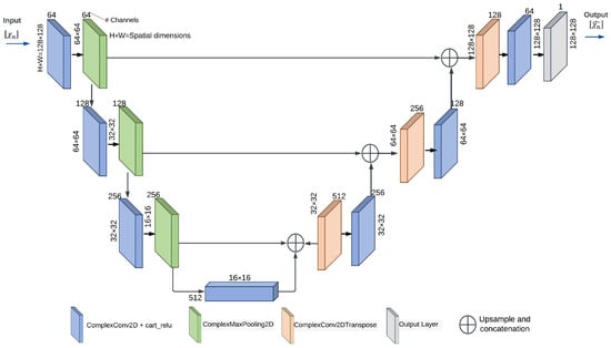
Figure 4.
Complex-valued U-NET (CV-UNET) architecture.
4. Construction of Complex-Valued Neural Networks
4.1. Complex-Valued Layers
The complex-valued neural network (CVNN) differs from the conventional real-valued neural network (RVNN) by incorporating complex-valued inputs. This characteristic allows CVNN to effectively process imaginary data without needing pre-processing steps to transfer them into the domain of real value. In a CVNN, each layer operates as a real-valued layer. However, the fundamental difference lies in that all computations occur within the complex domain, and the parameters that can be adjusted during training are complex-valued.
4.1.1. Complex Convolutional Layer
The convolutional layers exhibit similarity to conventional convolutional layers employed in neural networks that operate on real-valued data, although with modifications to accommodate complex numbers. In order to conduct a complex domain convolution that emulates a conventional real-valued 2-D convolution, the process involves convolving a complex filter matrix with a complex vector . In this context, A and B represent real matrices, while x and y denote real vectors. This approach is used to simulate complex arithmetic using real-valued entities. The convolution of the vector h with the filter F can be expressed as follows [21]:
The convolution operation can be represented using matrix notation to denote the real and imaginary components as follows:
4.1.2. Complex Dense Layer
A complex dense layer in a CVNN is conceptually similar to a fully connected layer in RVNN; however, it is adapted to manage complex-valued inputs and implements the operation [27]:
where the activation function, denoted , is applied element-wise and provided as the activation argument. The matrix known as W represents the weights generated by the layer. The bias vector is a vector that is generated by the layer and exhibits bias. The data types supported by this layer include both complex and real numbers. Complex dense layers are a specific category of layers within complex-valued neural networks, which possess the inherent ability to be seamlessly extended due to the well-defined operations of addition and multiplication within the complex domain.
4.1.3. Complex Pooling Layers
The placement of the pooling layer in a convolutional neural network (CNN) is after the convolutional layer. The purpose of this function is to provide a concise representation of the existence of features in patches of feature maps following the convolution operation. Therefore, this layer is commonly referred to as the downsampling layer as it effectively decreases the dimensionality of the feature map and generates a lower resolution representation of the input signal. In addition, it is beneficial to omit unnecessary data in the input signals. The two most prevalent pooling calculations in the field are max pooling and average pooling. These computations involve determining the maximum and average values within a feature map’s filter size region. The implementation of pooling layers is not inherently straightforward. In the context of the complex domain, the values lack a natural ordering characteristic observed in real values. Consequently, the concept of a maximum value becomes ambiguous, making it unfeasible to apply a max pooling layer to the input directly. The method proposed in [28] suggests using the norm of the complex image as a means of comparison. This approach has been used to implement the layer [27].
4.1.4. Complex Upsampling Layers
Complex-valued neural networks (CVNNs) employ complex upsampling layers to enhance the spatial resolution of complex-valued feature maps while maintaining the magnitude and phase information.
4.2. Activation Functions
The activation function plays a crucial role in CVNNs as it controls the output of a neuron by evaluating its input. One of the distinguishing characteristics of complex-valued neural networks (CVNNs) is their activation functions, which must be nonlinear and complex. Activation functions are typically chosen to be piece-wise smooth as this property efficiently computes gradients. Exploring the complex domain presents intriguing opportunities for the development of innovative activation functions. However, extending a real-valued activation function into the complex domain is a plausible and intuitive strategy. The output of a neuron can be determined considering an input and weights , where M and N indicate the dimensions of the input and output correspondingly. The output y of any neuron can be expressed as follows [29]:
where f denotes a non-linear activation function that is applied element-wise.
4.2.1. Complex ReLU
Various activation functions have been suggested in the academic literature to address the challenges faced by complex-valued representations. The Complex Rectified Linear Unit () activation function has been used in our study and is defined as follows [21,30]:
where .
The activation function is a complex activation that independently applies Rectified Linear Units (ReLUs) to both the real and imaginary components of a neuron. The function satisfies the Cauchy–Riemann equations when both the real and imaginary components are simultaneously strictly positive or negative [21]. This condition corresponds geometrically to the situation in which the complex input lies in the first or third quadrants of the complex plane. In the first quadrant, the real and imaginary parts are both positive, and the argument falls within the intervals . In the third quadrant, both parts are negative, and falls within the intervals .
4.2.2. Output Layer Activation Function
In our three proposed models for performing a regression task, the absence of an explicitly specified activation function in the output layer implies that the model employs a linear activation function as the default choice. In other words, this activation function does not change the input type, and the output layer is expressed without any nonlinearity [27]. The current configuration has been designed to enable the model to make predictions of continuous values without any additional modification. In the domain of CVNNs utilized for regression, the absence of an explicit declaration of an activation function in the output layer signifies that the model produces complex-valued numbers in their original form without any nonlinear transformation.
4.3. Complex Weight Initialization
The initialization process is crucial in mitigating the potential problems related to vanishing or expanding gradients. To achieve this objective, a consistent methodology is used, as described in [31,32], which involved formulating the problem in terms of the variance of the weight magnitudes, following a Rayleigh distribution [33]. A complex weight can be represented either in polar form as follows:
where is the magnitude, and is the phase, or equivalently in rectangular form as . Assuming the real and imaginary parts are zero-mean and independent, the variance of a complex weight can be written as follows:
If the phase is uniformly distributed over , then the expected value of the complex weight becomes zero, that is, , and the variance simplifies to the following:
To ensure the proper scaling of the weights and preserve the variance of the activations across layers, the expected squared magnitude of the weights is set according to the generalized Glorot initialization [31] for complex-valued parameters:
where and denote the number of input and output neurons of the layer, respectively. This formulation maintains variance stability during forward and backward propagation and helps prevent issues such as vanishing or exploding gradients in complex-valued neural networks.
4.4. Optimization and Learning in CVNNs
Learning in neural networks involves the adjustment of network weights to optimize learning objectives, such as minimizing a loss function. This process is analogous to that of RVNNs. However, in the context of CVNNs, learning involves complex numbers. In general, the minimization operation can be expressed as follows:
where denotes the ground truth, and denotes the values estimated by the network, whereas represents the Hankel structured matrix of the estimated values , and r represents the rank of the Hankel structured matrix. It should be noted that this matrix is strongly associated with convolution operations in the convolutional neural network (CNN), as discussed in [34].
It is essential to note that in the case of CVNNs, the loss or cost function to be minimized will yield a real-value outcome. This is because it is not feasible to search for the minimum of two complex numbers [27]. Hence, the error or loss for our regression task has been calculated using the Mean Squared Error (MSE) given the ground truth and the predicted output as complex numbers, represented as and , respectively. The loss function can be represented as follows:
where and represent the real and imaginary difference between the ground truth and the prediction, respectively.
5. Numerical Results
In this section, we provide a comprehensive explanation of the setup configurations outlined in this research, including specific information on the features of the dataset and the parameters of the neural networks. Furthermore, the performance assessment of three distinct variants of CVNNs is discussed using a dataset of breast dielectric profiles. To establish a benchmark for comparison, we also employ RVNNs with the same architecture as the proposed CVNNs, which allows us to evaluate the effectiveness of our complex network architectures.
5.1. Preprocessing of MRI Images
The breast phantoms used in this study were obtained from the University of Wisconsin Computational Laboratory (UWCEM) repository [35]. Each phantom consists of a 3-D grid of cubic voxels, each measuring 0.5 mm × 0.5 mm × 0.5 mm. The breast model comprises a skin layer with an approximate thickness of , a subcutaneous fat layer at the base of the breast measuring approximately in thickness, and a muscle chest wall with a thickness of . The analysis focused on coronal plane samples that were randomly selected from the 3-D maps. Hence, three 2-D models have been used in this study. These models are classified as follows: Class 1 (Mostly Fatty), Phantom 1, Breast ID: 071904; Class 2 (Scattered Fibroglandular), Phantom 1, Breast ID: 012204; and Class 3 (Heterogeneously Dense), Phantom 2, Breast ID: 070604PA2. The scattered fields were generated with respect to an initial image dimension of 128 × 128 pixels, whereas the resulting image dimension is 64 × 64 pixels. As shown in Figure 5, a with dimensions of × was considered. A total of 11 receivers and 11 transmitters are evenly distributed along the circumference of a circular area outside of . The radius of this circular area measures . The frequency of the incident field is set at a constant value of 1 . Breast models containing randomly inserted tumors with radii ranging from to are located within the . The feature maps were initially estimated using the quadratic BIM approach. In order to obtain an initial estimate of the total field, we employed the incident fields at the beginning of the iterative process. Later, a quadratic programming approach was used to obtain the initial contrast estimate , which was then used as input for the proposed neural network models to improve the reconstruction process.
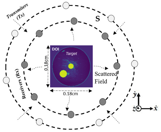
Figure 5.
Schematic representation of the measurement setup.
Data Normalization
The data normalization process aims to minimize the variability within the dataset, enhancing the performance and stability of the model during training. Normalization involves transforming the scale of features to ensure that they are comparable, mainly when the data elements exhibit substantial variations in scale. This methodology accelerates the rate at which the model attains an optimal solution during the training process. Normalization of the data enhances the interpretability and comparability of the model coefficients, facilitating the interpretation of the results. The present study used the minimum–maximum value-based normalization method [36] to examine the regression performance using the [0, 1] scale. The equation employed for this purpose is given as follows:
where and represent the minimum and maximum values of the ith characteristic, respectively. The lower and upper constraints used for the rescaling of the data are represented by the variables nMin and nMax, respectively.
Figure 6 shows a graphical representation of normalized and unnormalized data.
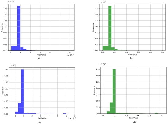
Figure 6.
Data normalization: (a) histogram of non-normalized data for network input, (b) histogram of normalized data for network input, (c) histogram of non-normalized data for network output (ground Truth), and (d) histogram of normalized data for network output (ground Truth).
5.2. Learning Process
The dataset has a total of 1500 images, with 80% of the images allocated for training purposes and the remaining 20% utilized for network validation. The purpose of utilizing validation data is to assess the performance of the model during the training process. The three proposed models, CV-MLP, CV-CNN, and CV-UNET, were implemented using Python 3.10 programming and simulated on an Nvidia GeForce RTX 3060 graphics processing unit (GPU). The datasets utilized for CV-MLP, CV-CNN, and CV-UNET are the same. The Adam optimizer is employed for model compilation in all three models, utilizing a learning rate of 0.001. The mean square error loss function is employed, while the metric employed is the Relative Error . The models are subsequently trained using the training data for 40 epochs, employing a batch size 32.
5.3. Evaluation
Three CVNNs, namely, CV-MLP, CV-CNN, and CV-UNET, were trained for 40 epochs to perform regression tasks. The input in these CVNNs consisted of complex-valued dielectric profiles () estimated using the quadratic BIM approach. On the other hand, the CVNN output () contained complex ground-truth dielectric profiles. Each CVNN was evaluated using the metrics and , which were applied to the breast model dataset. Figure 7 shows the progress of CVNN training in 40 epochs, as evidenced by the metrics and . A clear correspondence is observed between the complexity of the suggested networks and their reconstruction error. CV-UNET exhibits greater performance compared to both CV-CNN and CV-MLP.
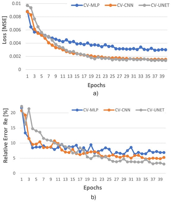
Figure 7.
Comparison of the outcomes derived from the validation process of the three CVNNs: CV-MLP, CV-CNN, and CV-UNET: (a) Validation Loss () and (b) Validation ().
According to the findings shown in Table 1, it can be observed that complex-valued networks exhibit superior performance compared to real-valued networks in terms of both mean squared error and mean relative error. Although the initial observation may suggest that the difference in error values is not significant, it is essential to recognize that the use of CVNNs offers a distinct advantage in directly yielding complex permittivity values as network output. This single training procedure generates values for epsilon () and sigma () for the reconstructed breast profiles. In contrast, when training networks with real data (RVNN), it is necessary to train the real and imaginary components separately, which is time-consuming to obtain comparable results. As shown in Table 2, the RVNN architectures exhibit approximately double the training time and memory usage compared to their CVNN counterparts. This increase is due to the fact that, in RVNNs, real and imaginary components are trained separately, effectively requiring two passes, one for each part. In contrast, CVNNs handle complex-valued computations jointly within a unified framework, which improves efficiency and reduces computational overhead.

Table 1.
Evaluation metrics.

Table 2.
Computational requirements comparison between CVNN and RVNN architectures.
To evaluate the stability and consistency of the proposed CVNN-based architectures, each model was trained independently five times. Table 3 presents the mean and standard deviation of the validation loss and relative error on these runs. The results demonstrate that CV-UNET achieves the most accurate and stable performance, followed by CV-CNN and CV-MLP.

Table 3.
Mean and standard deviation of performance metrics across 5 runs.
In order to assess the impact of optimization strategies on model performance, we performed a series of experiments using two widely adopted optimizers, Adam and Stochastic Gradient Descent (SGD), with learning rates of 0.001 and 0.01. Table 4 presents the relative error validation and loss (MSE) obtained for each model in these configurations. The results indicate that the Adam optimizer with a learning rate of 0.001 consistently outperforms other settings across all architectures (CV-MLP, CV-CNN, and CV-UNET), yielding lower reconstruction error and improved convergence. In contrast, the performance of SGD, particularly at lower learning rates, was less stable and led to significantly higher errors in some cases. These findings support the use of Adam (0.001) as a robust and reliable choice for training the proposed models.

Table 4.
Validation Loss and Relative Error (%) using different optimizers and learning rates.
Figure 8 presents an illustrative demonstration of prediction utilizing our proposed CVNNs models. These models employ complex-valued neurons and their output is visually represented by 2-D Cartesian diagrams. After performing validation, it becomes evident that CV-UNET demonstrates outstanding performance as its predictions align with the actual ranges for (2.5–67) and (0–1.8). In contrast, CV-CNN encounters difficulties in this aspect as its results are above the true thresholds for and . Finally, the CV-MLP model demonstrates the least desirable fit level as its predictions deviate significantly from the true values, surpassing 100 for and approaching 3 for .

Figure 8.
Comparison between the measured data and the predicted data using the three CVNNs proposed: (a) complex-valued multilayer perceptron (CV-MLP), (b) complex-valued convolutional neural network (CV-CNN), and (c) complex-valued U-NET (CV-UNET).
The breast models illustrated in Figure 9 exhibit the results obtained from our three suggested CVNNs. In general, these networks demonstrate favorable performance. However, it is essential to highlight particular observations. CV-MLP demonstrates limitations in accurately detecting the tiniest tumor within class 3 and 2 breast models. In contrast, CV-CNN shows slightly superior performance in detecting the tumor.
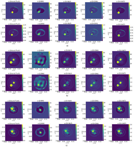
Figure 9.
Reconstruction of the dielectric profiles of the breast models using the quadratic BIM followed by three types of CVNNs proposed: CV-MLP, CV-CNN, and CV-UNET. (a) Representative model from Class 1, (b) representative model from Class 2, and (c) representative model from Class 3.
Meanwhile, the U-NET model excels in visualizing the tumor and provides a more accurate representation. Therefore, the CV-UNET model demonstrates superior coherence in finer details with respect to the ground truth in both real and imaginary components. As shown in Table 1, CV-UNET demonstrates a notable improvement in recovering intricate details, with a 53.86% improvement compared to CV-MLP and a 36.04% improvement compared to CV-CNN.
Building upon the global reconstruction discussed above, it is also important to consider how anatomical variability can influence model performance. The UWCEM database provides breast phantoms categorized into three classes according to tissue density. Specifically, Class 1 corresponds to the least dense breast conformation, Class 2 to a moderately dense structure, and Class 3 to the densest tissue distribution. In this study, a balanced number of samples was used in the three classes to ensure fair evaluation. Although the presented quantitative results focus on the overall performance of reconstruction, preliminary qualitative observations suggest that the reconstruction task becomes increasingly challenging with higher tissue density, particularly in Class 3, due to greater heterogeneity in dielectric properties.
Upon comparing RVNN (Figure 10), it is evident that both RV-MLP and RV-CNN exhibit superior quality in reconstructing the real component instead of the imaginary part . This observation is also supported by the errors in Table 1. However, it has been shown that RV-UNET generally exhibits superior performance when used for the dielectric profile regression task.
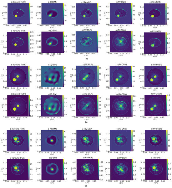
Figure 10.
Reconstruction of the dielectric profiles of the breast models using the quadratic BIM followed by three types of RVNNs: RV-MLP, RV-CNN, and RV-UNET. (a) Representative model from Class 1, (b) representative model from Class 2, and (c) representative model from Class 3.
In the performance of CVNNs (see Figure 9) with RVNNs (refer to Figure 10), it is evident that CVNNs present notable benefits, particularly in the context of tasks related to complex data. Firstly, it should be noted that CVNNs demonstrate a notable proficiency in processing complex-valued input, hence enabling them to capture the interactions between real and imaginary components more efficiently. The inherent capability of CVNNs produces improved reconstructions of the real component and the imaginary component , thus facilitating more precise and comprehensive modeling of intricate processes. The use of CVNNs has proven to be beneficial in our specific scenario involving the analysis of electromagnetic characteristics, where both components play a crucial role.
In addition, CVNNs have the potential to attain performance comparable or superior to RVNNs while utilizing fewer parameters, thereby enhancing the computing efficiency.
Furthermore, the improved reconstruction quality achieved by the proposed CVNN-based approach has the potential to offer significant clinical benefits. Enhanced spatial resolution and the recovery of dielectric contrast may allow for more accurate localization and delineation of anomalies, such as tumors, which is critical for early diagnosis and effective treatment planning. By reducing image artifacts and reconstruction errors, the method could also help decrease the incidence of false positives and false negatives, thus improving the reliability of the diagnostic.
To further evaluate the adaptability of the proposed method beyond breast imaging, additional experiments were carried out using brain models. These tests demonstrated that the reconstruction framework maintains its performance when applied to different anatomical structures, confirming its potential for broader biomedical imaging applications. The results of these experiments have been published in a related conference paper [37], supporting the generalization capabilities of the approach.
To support reproducibility, the source code and trained models have been made publicly available at https://github.com/AlexandraMFA/CVNNs.git (accessed on 25 April 2025).
6. Conclusions
The implementation of CVNNs within the medical imaging domain has demonstrated notable progress compared to conventional techniques in tackling the obstacles related to ISP. This study has showcased significant enhancements in image reconstructions employing a comprehensive methodology that integrates the BIM with quadratic programming for initial estimation and then utilizing three specific CVNNs to refine and improve the dielectric reconstructions. It has been determined through a rigorous evaluation that, among CVNN variants, CV-UNET is the most efficient, followed by CV-CNN, and CV-MLP is the least efficient in performance. One of the main advantages of CVNNs over RVNNs is their ability to handle complex value inputs and generate complex value outputs. This feature streamlines the process by enabling the simultaneous extraction of and , eliminating the need for distinct training steps, a requirement when using RVNNs.
Despite promising results, this study presents certain limitations. The experiments were carried out using only synthetic breast phantoms from the UWCEM database, which can constrain the generalizability of the method to other anatomical structures and clinical imaging scenarios. As part of future work, we intend to validate the proposed approach on more diverse datasets, including brain models and real patient data. In addition, our goal is to incorporate tumor segmentation techniques to enable a localized evaluation of reconstruction performance, particularly in regions of clinical interest.
Author Contributions
Conceptualization, A.M.F. and V.J.H.; methodology, A.M.F.; software, A.M.F.; validation, A.M.F., V.J.H., O.D.D., and M.B.P.; formal analysis, A.M.F. and C.P.-A.; investigation, A.M.F. and V.J.H.; resources, A.M.F., V.J.H., C.P.-A., M.J.L., O.D.D., and M.B.P.; data curation, C.P.-A. and M.J.L.; writing—original draft preparation, A.M.F. and V.J.H.; writing—review and editing, C.P.-A. and M.J.L.; visualization, M.B.P. and O.D.D.; supervision, C.P.-A. and M.J.L.; project administration, A.M.F.; funding acquisition, A.M.F., V.J.H., C.P.-A., M.J.L., M.B.P., and O.D.D. All authors have read and agreed to the published version of the manuscript.
Funding
This research received no external funding.
Data Availability Statement
Data is contained within the article. The original contributions presented in this study are included in the article. The dataset can be accessed at: https://github.com/AlexandraMFA/CVNNs.git (accessed on 25 April 2025).
Acknowledgments
The authors express their sincere gratitude to the University of Calabria, Italy, for the support provided during the development of this work. In particular, we extend our appreciation to the Department of Computer Engineering, Modeling, Electronics, and Systems, DIMES. We also extend our heartfelt thanks to the Escuela Superior Politécnica de Chimborazo, ESPOCH, Ecuador, and Universitat Politècnica de Catalunya for its valuable support and collaboration in this research.
Conflicts of Interest
The authors declare no conflicts of interest. The funders had no role in the design of the study; in the collection, analysis, or interpretation of data; in the writing of the manuscript; or in the decision to publish the results.
References
- Chen, X. Computational Methods for Electromagnetic Inverse Scattering; Wiley: Hoboken, NJ, USA, 2018. [Google Scholar]
- Pastorino, M. Microwave Imaging; Wiley: Hoboken, NJ, USA, 2010; Volume 208. [Google Scholar]
- Wang, Y.M.; Chew, W.C. An iterative solution of the two-dimensional electromagnetic inverse scattering problem. Int. J. Imaging Syst. Technol. 1989, 1, 100–108. [Google Scholar] [CrossRef]
- Chew, W.C.; Wang, Y.M. Reconstruction of two-dimensional permittivity distribution using the distorted Born iterative method. IEEE Trans. Med. Imaging 1990, 9, 218–225. [Google Scholar] [CrossRef]
- van den Berg, P.M.; Kleinman, R.E. A contrast source inversion method. Inverse Probl. 1997, 13, 1607. [Google Scholar] [CrossRef]
- Chen, X. Subspace-based optimization method for solving inverse-scattering problems. IEEE Trans. Geosci. Remote Sens. 2010, 48, 42–49. [Google Scholar] [CrossRef]
- Sarker, I.H. Machine learning: Algorithms, real-world applications and research directions. Soc. Netw. Comput. Sci. 2021, 2, 1–21. [Google Scholar] [CrossRef]
- Sanghvi, Y.; Kalepu, Y.; Khankhoje, U.K. Embedding deep learning in inverse scattering problems. IEEE Trans. Comput. Imaging 2020, 6, 46–56. [Google Scholar] [CrossRef]
- Ambrosanio, M.; Franceschini, S.; Pascazio, V.; Baselice, F. An end-to-end deep learning approach for quantitative microwave breast imaging in real-time applications. Bioengineering 2022, 9, 651. [Google Scholar] [CrossRef]
- Wei, Z.; Chen, X. Deep-learning schemes for full-wave nonlinear inverse scattering problems. IEEE Trans. Geosci. Remote Sens. 2019, 57, 1849–1860. [Google Scholar] [CrossRef]
- Marashdeh, Q.; Warsito, W.; Fan, L.-S.; Teixeira, F.L. Nonlinear forward problem solution for electrical capacitance tomography using feed-forward neural network. IEEE Sens. J. 2006, 6, 441–449. [Google Scholar] [CrossRef]
- Marashdeh, Q.; Warsito, W.; Fan, L.-S.; Teixeira, F.L. A nonlinear image reconstruction technique for ECT using a combined neural network approach. Meas. Sci. Technol. 2006, 17, 2097–2103. [Google Scholar] [CrossRef]
- Han, Y.S.; Yoo, J.; Ye, J.C. Deep Residual Learning for Compressed Sensing CT Reconstruction via Persistent Homology Analysis. Available online: https://arxiv.org/abs/1611.06391 (accessed on 17 November 2024).
- Jin, K.H.; McCann, M.T.; Froustey, E.; Unser, M. Deep convolutional neural network for inverse problems in imaging. IEEE Trans. Image Process 2017, 26, 4509–4522. [Google Scholar] [CrossRef] [PubMed]
- Lee, C.; Hasegawa, H.; Gao, S. Complex-Valued Neural Networks: A Comprehensive Survey. IEEE/CAA J. Autom. Sin. 2022, 9, 1406–1426. [Google Scholar] [CrossRef]
- Nitta, T. Solving the XOR problem and the detection of symmetry using a single complex-valued neuron. Neural Netw. 2023, 16, 1101–1105. [Google Scholar] [CrossRef] [PubMed]
- Li, L.; Wang, L.G.; Teixeira, F.L.; Liu, C.; Nehorai, A.; Cui, T.J. DeepNIS: Deep Neural Network for Nonlinear Electromagnetic Inverse Scattering. IEEE Trans. Antennas Propag. 2019, 67, 1819–1825. [Google Scholar] [CrossRef]
- Shao, W.; Du, Y. Microwave imaging by deep learning network: Feasibility and training method. IEEE Trans. Antennas Propag. 2020, 68, 5626–5635. [Google Scholar] [CrossRef]
- Yao, H.M.; Sha, W.E.I.; Jiang, L. Two-step enhanced deep learning approach for electromagnetic inverse scattering problems. IEEE Antennas Wirel. Propag. Lett. 2019, 18, 2254–2258. [Google Scholar] [CrossRef]
- Guo, L.; Song, G.; Wu, H. Complex-valued Pix2pix–deep neural network for nonlinear electromagnetic inverse scattering. Electronics 2021, 10, 6. [Google Scholar] [CrossRef]
- Trabelsi, C.; Bilaniuk, O.; Zhang, Y.; Serdyuk, D.; Subramanian, S.; Santos, J.F.; Mehri, S.; Rostamzadeh, N.; Bengio, Y.; Pal, C.J. Deep complex networks. arXiv 2017, arXiv:1705.09792. [Google Scholar]
- Hirose, A. Complex-Valued Neural Networks: Advances and Applications; John Wiley & Sons: Hoboken, NJ, USA, 2012. [Google Scholar]
- Scardapane, S.; Van Vaerenbergh, S.; Hussain, A.; Uncini, A. Complex-valued neural networks with non-parametric activation functions. IEEE Trans. Emerg. Top. Comput. Intell. 2018, 4, 140–150. [Google Scholar] [CrossRef]
- Barrachina, J.A. Complex-Valued Neural Networks for Radar Applications. Ph.D. Thesis, Université Paris-Saclay, Gif-sur-Yvette, France, 2022. Available online: https://theses.hal.science/tel-03927422 (accessed on 21 April 2025).
- Currie, G. Intelligent imaging: Anatomy of machine learning and deep learning. J. Nucl. Med. Technol. 2019, 47, 273–281. [Google Scholar] [CrossRef]
- Costanzo, S.; Flores, A.; Buonanno, G. Fast and Accurate CNN-Based Machine Learning Approach for Microwave Medical Imaging in Cancer Detection. IEEE Access 2023, 11, 66063–66075. [Google Scholar] [CrossRef]
- Barrachina, J.A. Complex-Valued Neural Network (CVNN). 2022. Available online: https://complex-valued-neural-networks.readthedocs.io/en/latest/index.html (accessed on 29 November 2024).
- Zhang, Z.; Wang, H.; Xu, F.; Jin, Y.-Q. Complex-valued convolutional neural network and its application in polarimetric SAR image classification. IEEE Trans. Geosci. Remote Sens. 2017, 55, 7177–7188. [Google Scholar] [CrossRef]
- Bassey, J.; Qian, L.; Li, X. A survey of complex-valued neural networks. arXiv 2021, arXiv:2101.12249. [Google Scholar]
- Cao, Y.; Wu, Y.; Zhang, P.; Liang, W.; Li, M. Pixel-wise PolSAR image classification via a novel complex-valued deep fully convolutional network. Remote Sens. 2019, 11, 2653. [Google Scholar] [CrossRef]
- Glorot, X.; Bengio, Y. Understanding the difficulty of training deep feedforward neural networks. In Proceedings of the 13th International Conference on Artificial Intelligence and Statistics, Sardinia, Italy, 13–15 May 2010; pp. 249–256. [Google Scholar]
- He, K.; Zhang, X.; Ren, S.; Sun, J. Delving deep into rectifiers: Surpassing human-level performance on ImageNet classification. In Proceedings of the IEEE International Conference on Computer Vision (ICCV), Santiago, Chile, 7–13 December 2015; pp. 1026–1034. [Google Scholar]
- Rayleigh, L. On the resultant of a large number of vibrations of the same pitch and of arbitrary phase. Phil. Mag. 1880, 43, 259–272. [Google Scholar] [CrossRef]
- Ye, J.C.; Han, Y.; Cha, E. Deep convolutional framelets: A general deep learning framework for inverse problems. SIAM J. Imaging Sci. 2018, 11, 991–1048. [Google Scholar] [CrossRef]
- Zastrow, E.; Davis, S.K.; Lazebnik, M.; Kelcz, F.; Veen, B.D.V.; Hagness, S.C. Development of anatomically realistic numerical breast phantoms with accurate dielectric properties for modeling microwave interactions with the human breast. IEEE Trans. Biomed. Eng. 2008, 55, 2792–2800. [Google Scholar] [CrossRef]
- Singh, D.; Singh, B. Investigating the impact of data normalization on classification performance. Appl. Soft Comput. 2020, 97, 105524. [Google Scholar] [CrossRef]
- Costanzo, S.; Flores, A. CVNN Approach for Microwave Imaging Applications in Brain Cancer: Preliminary Results. In Proceedings of the 2024 18th European Conference on Antennas and Propagation (EuCAP), Glasgow, UK, 17–22 March 2024; pp. 1–3. [Google Scholar]
Disclaimer/Publisher’s Note: The statements, opinions and data contained in all publications are solely those of the individual author(s) and contributor(s) and not of MDPI and/or the editor(s). MDPI and/or the editor(s) disclaim responsibility for any injury to people or property resulting from any ideas, methods, instructions or products referred to in the content. |
© 2025 by the authors. Licensee MDPI, Basel, Switzerland. This article is an open access article distributed under the terms and conditions of the Creative Commons Attribution (CC BY) license (https://creativecommons.org/licenses/by/4.0/).