


A Privacy-Preserving Authentication Scheme Using PUF and Biometrics for IoT-Enabled Smart Cities


Abstract
1. Introduction
1.1. Research Contribution
- This work analyzes the scheme by Nyangaresi et al. [16] and demonstrates that it has security vulnerabilities, such as susceptibility to insider, sensor node capture, user impersonation, and random number leakage attacks.
- This work proposes a privacy-preserving authentication scheme for smart cities to address the security vulnerabilities of the scheme by Nyangaresi et al. [16]. The proposed scheme employs biometric information as an additional factor for secure user verification and applies PUF technology to defend against physical threats.
- This work demonstrates the security of the proposed scheme via an informal security analysis, which reveals the security properties and resistance to various attacks. The proposed scheme ensures mutual authentication and secure communication by verifying the legitimacy of entities.
- This work conducts formal analyses using Burrows–Abadi–Needham (BAN) logic, the real-or-random (ROR) model, and Automated Validation of Internet Security Protocols and Applications (AVISPA) simulation tools. The analyses evaluate mutual authentication, session key security, and resistance to man-in-the-middle (MitM) and replay attacks.
- This work demonstrates that the proposed scheme performs better than others in smart city applications. The proposed scheme is more suitable and efficient than other schemes for IoT-based smart city environments.
1.2. Organization
2. Related Work
3. Preliminaries
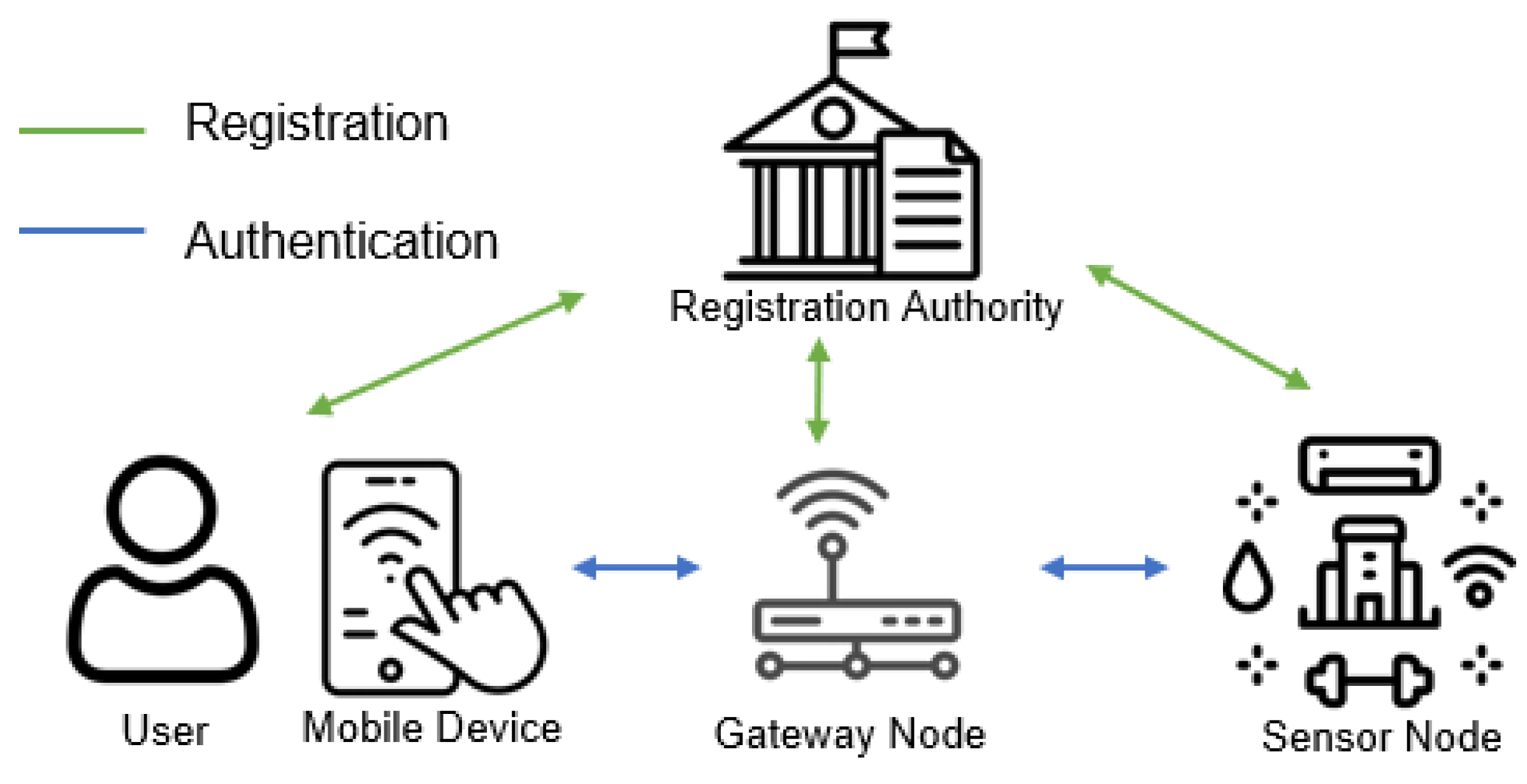
3.1. Network Model
- Registration authority: The registration authority has sufficient storage capacity and computation power to register users, gateway nodes, and sensor nodes in the smart city. The registration authority is a trusted entity that manages the identification information for the user, gateway node, and sensor node.
- User: Users can employ their mobile devices to obtain sensor data remotely. To access data, users must first register with the registration authority. After registration, users can use their mobile devices to communicate with sensors through a gateway for successful authentication.
- Gateway node: The gateway is considered a semi-trusted entity in the scheme. Although the gateway can attempt to reveal the data using its information, it works properly as a bridge between users and sensor nodes in wireless networks. The sensor data must be authenticated by passing the gateways through insecure channels. Each gateway is responsible for managing the sensors within its designated region.
- Sensor node: The sensors are deployed everywhere in smart cities to collect environmental data. Before deployment, sensors register at the registration authority to obtain secret parameters for authentication. Through the gateway, sensors transfer collected data to legitimate users who require data. These sensors have limited computational power and storage capabilities.
3.2. Mathematical Preliminaries
3.2.1. Fuzzy Extractors
- : When a user inputs the biometric data , the probabilistic function generates a secret string and a helper string , where l and ∗ are lengths of bit strings.
- : When a user reimprints biometric data , could have some noise compared to the initial biometric data B. The procedure recovers the value using P.
3.2.2. Physical Unclonable Functions
- The PUF has unclonable properties that prevent replication.
- The PUF response is unpredictable due to its physical characteristics.
- In the same device, the PUF responds identically to the same challenge.
- The PUF circuit is easy to estimate and implement.
3.3. Adversary Model
- Message control: The adversary can intercept, alter, delete, and inject malicious or forged messages during communication over a wireless public channel.
- Device compromise: The adversary can extract sensitive data from lost or stolen mobile devices. Through power analysis attacks [41], the adversary can retrieve private information, including credentials and other stored parameters.
- Various attacks: The adversary can perform various attacks, such as replay, privileged insider, impersonation, and sensor node capture.
4. Review of Nyangaresi et al.’s Scheme
4.1. System Setup Phase
4.2. Registration Phase
4.2.1. Sensor Node Registration
- Step 1:
- The selects a unique identity for and derives a secret key . Those parameters are sent to via a secure channel.
- Step 2:
- Upon receiving the message , the stores the parameters.
4.2.2. User Registration
- Step 1:
- Through the , the generates a unique identity , password , and random number . Next, computes and inputs biometric data into the . Then, composes and sends a registration request to through a secure channel.
- Step 2:
- The chooses a random codephrase for the , and derives , , , , . After that, stores in its database and constructs a registration response . The message is sent to over a secure channel.
- Step 3:
- Upon receiving the response, stores parameters in the memory of .
4.3. Login, Authentication, and Key Negotiation Phase
- Step 1:
- The inputs into the , which uses an error correcting code to compute and recover if the Hamming distance between and is within the acceptable threshold. Afterward, checks whether , where . After the biometric validation is successfully completed, inputs and . Then, the computes and checks whether . If validated, chooses random nonces and computes , , , , , , , where . Finally, composes the login request message and sends it to the through a public channel.
- Step 2:
- After receiving , the computes , . Next, confirms whether exists in its database. When is found and identified, computes , , , , , . Then, confirms whether . If validated, generates and computes , , , , . Finally, construct the authentication message and sends it to the over a public channel.
- Step 3:
- Upon obtaining , calculates , , , . Subsequently, checks whether , and, if equal, generates as a random nonce. Then, calculates , , . Finally, composes the authentication response message , which is transmitted to via a public channel.
- Step 4:
- After receiving from the , computes , , . If equals , computes , , . Finally, constructs that is sent to the .
- Step 5:
- computes , , , and . After that, checks whether . If is valid, the session key is set as and key negotiation is completed.
5. Cryptoanalysis of Nyangaresi et al.’s Scheme
5.1. Insider Attack
- Step 1:
- An adversary completes the authentication phase using his/her identity and password as a legitimate user. During this phase, intercepts the message and derives the secret key which is shared between and .
- Step 2:
- The eavesdrops parameters from the messages exchanged by another user via a public channel. Since the parameter is consistently used during the authentication phase, can obtain the session key between and .
- Step 3:
- Using the secret key , computes , . Next, derives , , and . Finally, can compute the session key .
5.2. Physical Capture Attack
5.3. User Impersonation Attack
- Step 1:
- An adversary generates random nonces and . Then, computes , .
- Step 2:
- Using the obtained parameters , computes , , and . Finally, can successfully compose and impersonate a user .
5.4. Random Number Leakage Attack
- Step 1:
- After obtaining parameters from the public messages, computes , , and .
- Step 2:
- Finally, calculates the .
6. Proposed Scheme
6.1. Registration Phase
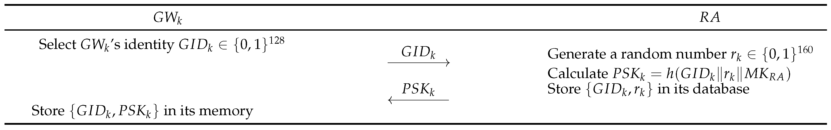
6.1.1. Gateway Node Registration
- Step 1:
- The gateway node selects its unique identity . Then, sends to as shown in Figure 2.
- Step 2:
- If the received does not exist in the database, processes a registration phase for . The generates a random number and computes . The stores in its database and sends to .
- Step 3:
- After receiving from , stores with in its memory.
6.1.2. Sensor Node Registration
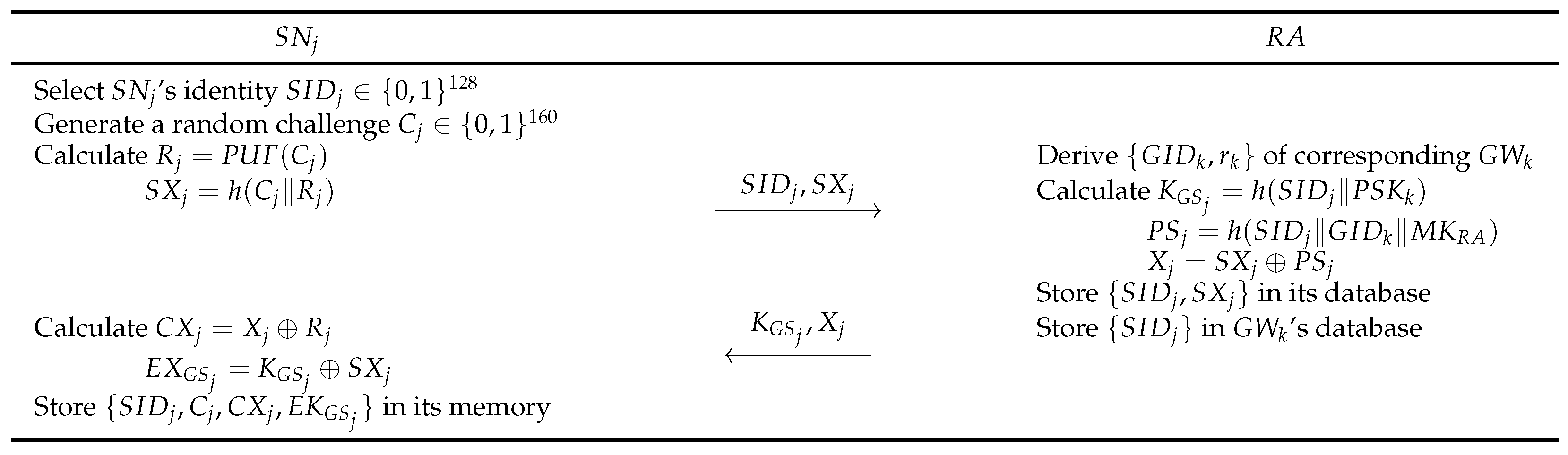
- Step 1:
- The sensor node selects its identity and generates a random challenge . calculates a PUF response , and . sends to .
- Step 2:
- If the does not exist in the database, derives corresponding parameters of , which is responsible for the area where will be deployed. Then, calculates , , and . The stores the sensor information in its database and in the gateway node database. Finally, transmit secret parameters to .
- Step 3:
- After receiving these parameters, calculates , . stores values .
6.1.3. User Registration
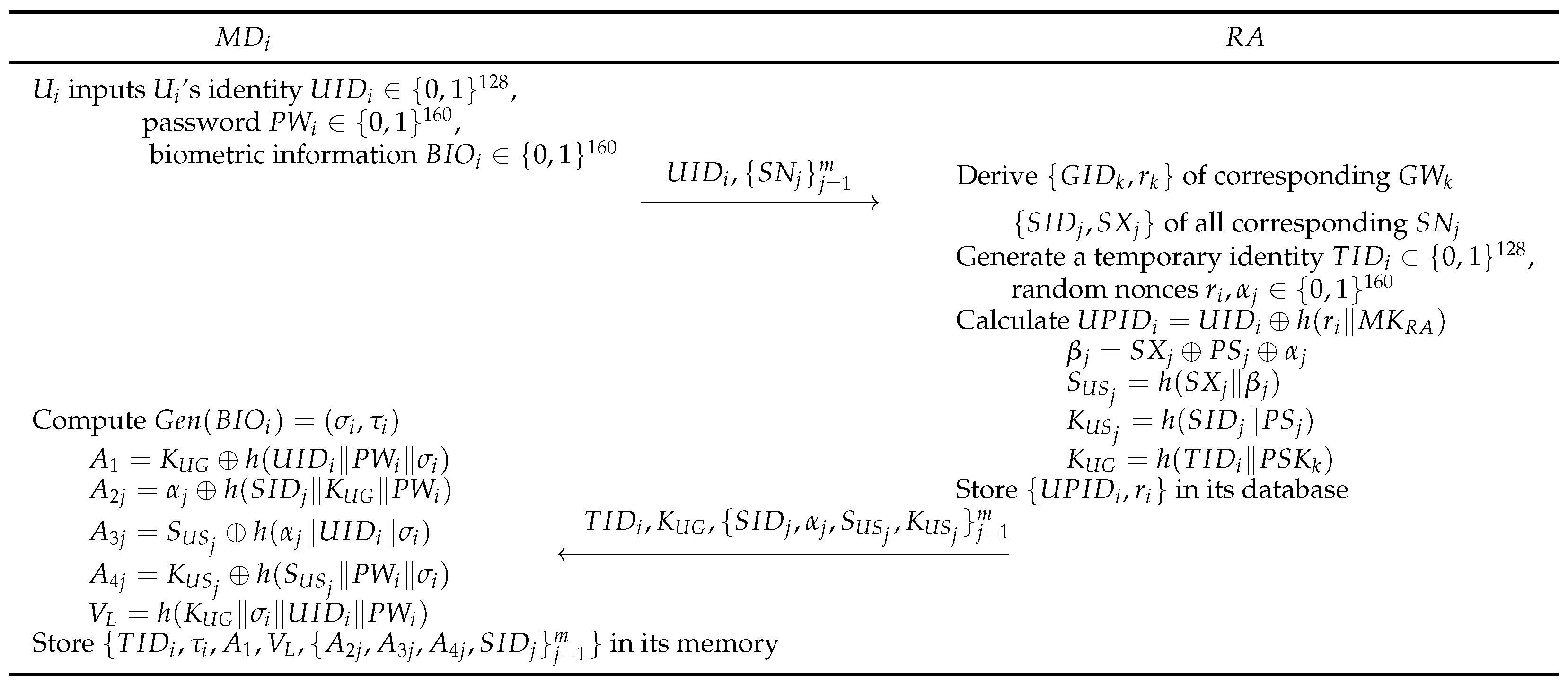
- Step 1:
- The user inputs ’s unique identity , password , and biometric data into . The requires access to sensor nodes , and sends the requirements and to .
- Step 2:
- The derives stored information of that communicates with , as well as that manages those sensors. Then, selects a temporary random identity and generates a random number . Then, calculates parameters , , , and required for authentication. The stores in its database and sends to .
- Step 3:
- When the response is received, computes a secret parameter and a helper string from , and encrypts secret keys using . The computes , , , , , and . Finally, stores parameters in its database and completes registration successfully.
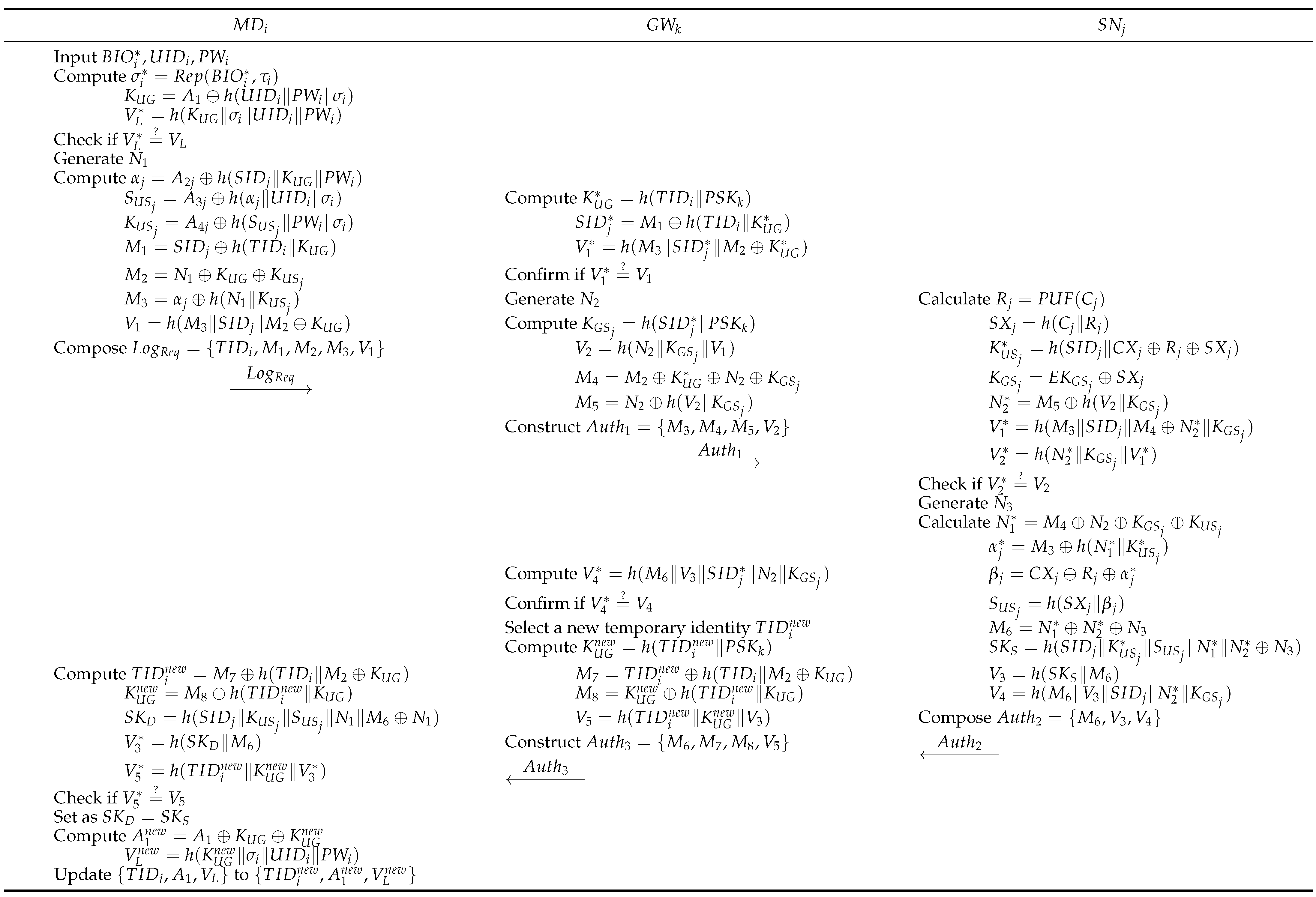
6.2. Login and Authentication Phase
- Step 1:
- The first inputs , and into . Then, computes , , . If equals , the login is successful and is authenticated. Next, generates and computes , , and . Then, composes the message , where , , , . The sends to .
- Step 2:
- Upon receipt of the message, the computes , , . Then, verifies whether . If this is valid, the generates and computes , , , . constructs the authentication message and transmits to .
- Step 3:
- On receiving , the calculates , , , , , , . After that, checks whether equals . If this is correct, generates and calculates , , , , , , , . Finally, sends to .
- Step 4:
- When receives the response from , computes and checks the validity of compared with . If the verification is successful, randomly selects a new temporary identity for subsequent communication of . Then, computes , , , . Finally, constructs the message and transmits it to .
- Step 5:
- After obtaining , computes , , , , , and . Next, verifies whether . If the values do not match, the session is aborted. Otherwise, the session key is set as , and key agreement is successful between and . Followed by the successful authentication phase, computes , and updates to . After that, erases from its database to prevent any backward key secrecy violations.
6.3. Dynamic Node Addition Phase
- Step 1:
- Before the new node is deployed, executes the sensor node registration phase. By following the Section 6.1.2, the stores and the stores in its memory.
- Step 2:
- After the successful registration of and its deployment, informs the gateway about its addition. The calculates , , and . The encrypts its identity by the secret key and sends it to .
- Step 3:
- After receiving the messages about a new sensor addition, the verify the legitimacy of by using . Then, broadcasts for the new node addition. Then, users can request access to the newly deployed node.
7. Security Analysis
7.1. Informal Analysis
7.1.1. Session Key Disclosure Attacks
7.1.2. Denial of Service Attacks
7.1.3. Replay Attacks
7.1.4. Desynchronization Attacks
7.1.5. Insider Attacks
7.1.6. Privileged Insider Attacks
7.1.7. User Impersonation Attacks
7.1.8. Man-in-the-Middle Attacks
7.1.9. Forgery Attacks
7.1.10. Physical Capture Attacks
7.1.11. Random Number Leakage Attacks
7.1.12. Mutual Authentication
7.1.13. Key Agreement
7.1.14. Anonymity and Untraceability
7.1.15. Perfect Forward Secrecy
7.1.16. Modeling Attacks
7.2. BAN Logic
7.2.1. Rules
7.2.2. Goals
- :
- :
- :
- :
7.2.3. Idealized Forms
- :
- :
- :
- :
7.2.4. Assumptions
- :
- :
- :
- :
- :
- :
- :
- :
- :
- :
- :
7.2.5. BAN Logic Proof
- Step 1:
- According to , we can obtain .
- Step 2:
- From the MMR using and , we can obtain .
- Step 3:
- From the FR using , we can obtain .
- Step 4:
- From the NVR using and , we can obtain .
- Step 5:
- According to , we can obtain .
- Step 6:
- From the MMR using and , we can obtain .
- Step 7:
- From the NVR using and , we can obtain .
- Step 8:
- According to , we can obtain .
- Step 9:
- From the MMR using and , we can obtain .
- Step 10:
- From the FR using , we can obtain .
- Step 11:
- From the NVR using and , we can obtain .
- Step 12:
- According to and , we can obtain .
- Step 13:
- From the MMR using and , we can obtain .
- Step 14:
- From the FR using , we can obtain .
- Step 15:
- From the NVR using and , we can obtain .
- Step 16:
- According to , we can obtain .
- Step 17:
- From the MMR using and , we can obtain .
- Step 18:
- From the FR using , we can obtain .
- Step 19:
- From the NVR using and , we can obtain .
- Step 20:
- Since the session key is , we can obtain from and . From , , and , we can obtain .
- Step 21:
- From the JR using , , , and , we can obtain and .
7.3. ROR Model
- Execute(, , ): can intercept the messages transmitted between , , and through a public channel. The query indicates an eavesdropping attack.
- CorruptD(): Using this query, obtains the data stored in the mobile device of a user .
- Send(, ): can transmit and receive a message between other participants , , and .
- Test(): This query executes a coin flip test to verify the semantic security of the session key. If , a random string is returned; if , the session key is returned. Otherwise, gets a value. The session key is secure if cannot distinguish between the random string and the session key.
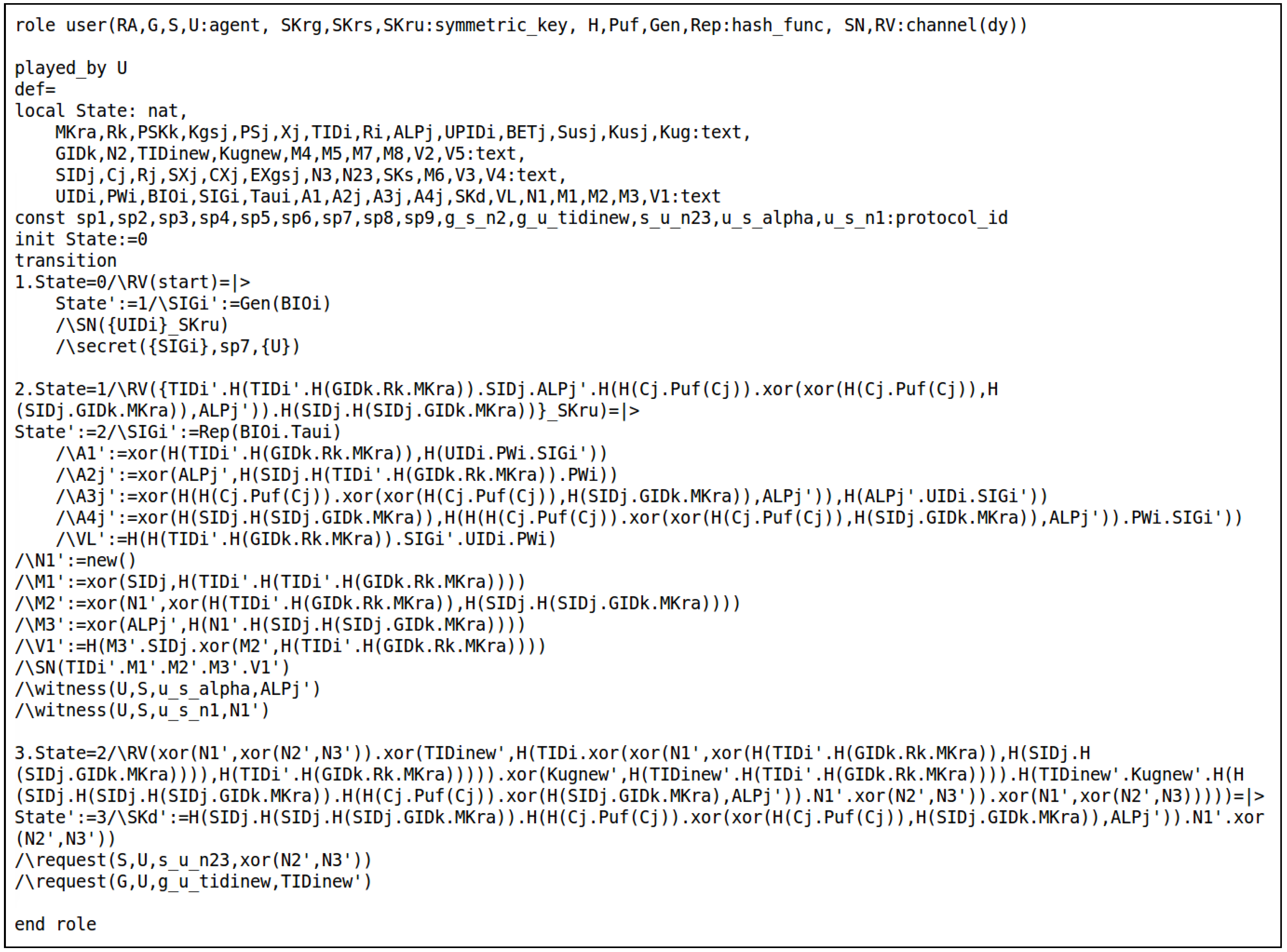
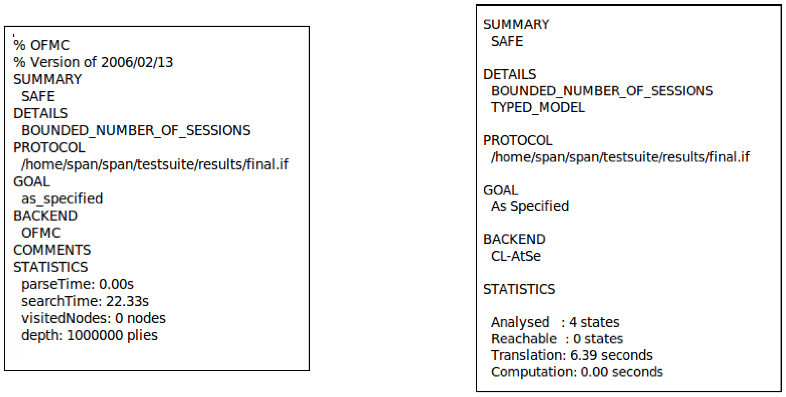
7.4. AVISPA Simulation
7.4.1. HLPSL Specification
7.4.2. AVISPA Simulation Result
8. Performance Comparison
8.1. Computational Costs
- GWN: Intel Core i5-11400 processor (Intel Corporation, Santa Clara, CA, USA), 24 GB RAM, 2.6 GHz, running Ubuntu 20.04 LTS 64-bit.
- User and Sensor: Raspberry Pi 4 Model B (Raspberry Pi Ltd., Cambridge, UK), 8 GB RAM, ARM Cortex-A72 1.5 GHz processor, running Ubuntu 20.04 LTS 64-bit.
8.2. Communication Costs
8.3. Energy Consumption
8.4. Security Features
9. Conclusions
Author Contributions
Funding
Data Availability Statement
Conflicts of Interest
References
- Gaur, A.; Scotney, B.; Parr, G.; McClean, S. Smart city architecture and its applications based on IoT. Procedia Comput. Sci. 2015, 52, 1089–1094. [Google Scholar] [CrossRef]
- Prajapat, S.; Gautam, D.; Kumar, P.; Jangirala, S.; Das, A.K.; Park, Y.; Lorenz, P. Secure lattice-based aggregate signature scheme for vehicular Ad Hoc networks. IEEE Trans. Veh. Technol. 2024, 73, 12370–12384. [Google Scholar] [CrossRef]
- Okonta, D.E.; Vukovic, V. Smart cities software applications for sustainability and resilience. Heliyon 2024, 10, e32654. [Google Scholar] [CrossRef]
- Belli, L.; Cilfone, A.; Davoli, L.; Ferrari, G.; Adorni, P.; Di Nocera, F.; Dall’Olio, A.; Pellegrini, C.; Mordacci, M.; Bertolotti, E. IoT-enabled smart sustainable cities: Challenges and approaches. Smart Cities 2020, 3, 1039–1071. [Google Scholar] [CrossRef]
- Kim, T.H.; Ramos, C.; Mohammed, S. Smart city and IoT. Future Gener. Comput. Syst. 2017, 76, 159–162. [Google Scholar] [CrossRef]
- Mishra, P.; Singh, G. Energy management systems in sustainable smart cities based on the internet of energy: A technical review. Energies 2023, 16, 6903. [Google Scholar] [CrossRef]
- Fabrègue, B.F.; Bogoni, A. Privacy and security concerns in the smart city. Smart Cities 2023, 6, 586–613. [Google Scholar] [CrossRef]
- Shafiq, M.; Gu, Z.; Cheikhrouhou, O.; Alhakami, W.; Hamam, H. The Rise of “Internet of Things”: Review and Open Research Issues Related to Detection and Prevention of IoT-Based Security Attacks. Wireless Commun. Mobile Comput. 2022, 2022, 8669348. [Google Scholar] [CrossRef]
- Eckhoff, D.; Wagner, I. Privacy in the smart city—Applications, technologies, challenges, and solutions. IEEE Commun. Surv. Tutorials 2017, 20, 489–516. [Google Scholar] [CrossRef]
- Ashraf, J.; Keshk, M.; Moustafa, N.; Abdel-Basset, M.; Khurshid, H.; Bakhshi, A.D.; Mostafa, R.R. IoTBoT-IDS: A Novel Statistical Learning-Enabled Botnet Detection Framework for Protecting Networks of Smart Cities. Sustain. Cities Soc. 2021, 72, 103041. [Google Scholar] [CrossRef]
- Martínez-Ballesté, A.; Pérez-Martínez, P.A.; Solanas, A. The pursuit of citizens’ privacy: A privacy-aware smart city is possible. IEEE Commun. Mag. 2013, 51, 136–141. [Google Scholar] [CrossRef]
- Balaji, S.; Nathani, K.; Santhakumar, R. IoT technology, applications and challenges: A contemporary survey. Wirel. Pers. Commun. 2019, 108, 363–388. [Google Scholar] [CrossRef]
- Yu, S.; Park, Y. A robust authentication protocol for wireless medical sensor networks using blockchain and physically unclonable functions. IEEE Internet Things J. 2022, 9, 20214–20228. [Google Scholar] [CrossRef]
- Sutrala, A.K.; Obaidat, M.S.; Saha, S.; Das, A.K.; Alazab, M.; Park, Y. Authenticated key agreement scheme with user anonymity and untraceability for 5G-enabled softwarized industrial cyber-physical systems. IEEE Trans. Intell. Transp. Syst. 2021, 23, 2316–2330. [Google Scholar] [CrossRef]
- Rao, P.M.; Deebak, B.D. Security and privacy issues in smart cities/industries: Technologies, applications, and challenges. J. Ambient Intell. Hum. Comput. 2023, 14, 10517–10553. [Google Scholar] [CrossRef]
- Nyangaresi, V.O.; Abduljabbar, Z.A.; Mutlaq, K.A.A.; Bulbul, S.S.; Ma, J.; Aldarwish, A.J.Y.; Honi, D.G.; Al Sibahee, M.A.; Neamah, H.A. Smart city energy efficient data privacy preservation protocol based on biometrics and fuzzy commitment scheme. Sci. Rep. 2024, 14, 16223. [Google Scholar] [CrossRef] [PubMed]
- Shuai, M.; Yu, N.; Wang, H.; Xiong, L. Anonymous authentication scheme for smart home environment with provable security. Comput. Secur. 2019, 86, 132–146. [Google Scholar] [CrossRef]
- Zou, S.; Cao, Q.; Wang, C.; Huang, Z.; Xu, G. A robust two-factor user authentication scheme-based ECC for smart home in IoT. IEEE Syst. J. 2021, 16, 4938–4949. [Google Scholar] [CrossRef]
- Kaur, D.; Kumar, D. Cryptanalysis and improvement of a two-factor user authentication scheme for smart home. J. Inf. Secur. Appl. 2021, 58, 102787. [Google Scholar] [CrossRef]
- Zou, S.; Cao, Q.; Lu, R.; Wang, C.; Xu, G.; Ma, H.; Cheng, Y.; Xi, J. A robust and effective 3-factor authentication protocol for smart factory in IIoT. Comput. Commun. 2024, 220, 81–93. [Google Scholar] [CrossRef]
- Rangwani, D.; Om, H. Four-factor mutual authentication scheme for health-care based on wireless body area network. J. Supercomput. 2022, 78, 5744–5778. [Google Scholar] [CrossRef]
- Xie, Q.; Li, K.; Tan, X.; Han, L.; Tang, W.; Hu, B. A secure and privacy-preserving authentication protocol for wireless sensor networks in smart city. EURASIP J. Wirel. Commun. Netw. 2021, 2021, 119. [Google Scholar] [CrossRef]
- Kumar, R.; Singh, S.; Singh, P.K. A secure and efficient computation based multifactor authentication scheme for Intelligent IoT-enabled WSNs. Comput. Electr. Eng. 2023, 105, 108495. [Google Scholar] [CrossRef]
- Badar, H.M.S.; Mahmood, K.; Akram, W.; Ghaffar, Z.; Umar, M.; Das, A.K. Secure authentication protocol for home area network in smart grid-based smart cities. Comput. Electr. Eng. 2023, 108, 108721. [Google Scholar] [CrossRef]
- Dodis, Y.; Reyzin, L.; Smith, A. Fuzzy extractors: How to generate strong keys from biometrics and other noisy data. In Proceedings of the Advances in Cryptology-Eurocrypt 2004, Interlaken, Switzerland, 2–6 May 2004; pp. 523–540. [Google Scholar]
- Sumalatha, U.; Prakasha, K.K.; Prabhu, S.; Nayak, V.C. A Comprehensive Review of Unimodal and Multimodal Fingerprint Biometric Authentication Systems: Fusion, Attacks, and Template Protection. IEEE Access 2024, 12, 64300–64334. [Google Scholar] [CrossRef]
- Ali, S.S.; Ganapathi, I.I.; Mahyo, S.; Prakash, S. Polynomial Vault: A Secure and Robust Fingerprint based Authentication. IEEE Trans. Emerging Top. Comput. 2021, 9, 612–625. [Google Scholar] [CrossRef]
- Blanton, M.; Aliasgari, M. Analysis of reusability of secure sketches and fuzzy extractors. IEEE Trans. Inf. Forensics Secur. 2013, 8, 1433–1445. [Google Scholar] [CrossRef]
- Zhang, M.; Marin, E.; Oswald, D.; Singelée, D. FuzzyKey: Comparing Fuzzy Cryptographic Primitives on Resource-Constrained Devices. In Proceedings of the International Conference on Smart Card Research and Advanced Applications, Lübeck, Germany, 11–12 November 2021; pp. 289–309. [Google Scholar]
- Maes, R. Physically Unclonable Functions: Constructions, Properties and Applications, 1st ed.; Springer: Berlin/Heidelberg, Germany, 2013. [Google Scholar]
- Gao, Y.; Al-Sarawi, S.F.; Abbott, D. Physical unclonable functions. Nat. Electron. 2020, 3, 81–91. [Google Scholar] [CrossRef]
- Chuang, K.-H.; Bury, E.; Degraeve, R.; Kaczer, B.; Linten, D.; Verbauwhede, I. A physically unclonable function using soft oxide breakdown featuring 0% native BER and 51.8 fJ/bit in 40-nm CMOS. IEEE J. Solid-State Circuits 2019, 54, 2765–2776. [Google Scholar] [CrossRef]
- Wang, W.-C.; Yona, Y.; Diggavi, S.N.; Gupta, P. Design and analysis of stability-guaranteed PUFs. IEEE Trans. Inf. Forensics Security 2018, 13, 978–992. [Google Scholar] [CrossRef]
- Alruwaili, O.; Alotaibi, F.M.; Tanveer, M.; Chaoui, S.; Armghan, A. PSAF-IoT: Physically secure authentication framework for the Internet of Things. IEEE Access 2024, 12, 78549–78561. [Google Scholar] [CrossRef]
- Sarbishaei, G.; Modarres, A.M.A.; Jowshan, F.; Khakzad, F.Z.; Mokhtari, H. Smart Home Security: An Efficient Multi-Factor Authentication Protocol. IEEE Access 2024, 12, 106253–106272. [Google Scholar] [CrossRef]
- Dolev, D.; Yao, A. On the security of public key protocols. IEEE Trans. Inf. Theory 1983, 29, 198–208. [Google Scholar] [CrossRef]
- Canetti, R.; Krawczyk, H. Universally composable notions of key exchange and secure channels. In Proceedings of the International Conference on the Theory and Applications of Cryptographic Thechniques (EUROCRYPT’02), Amsterdam, The Netherlands, 28 April–2 May 2002; pp. 337–351. [Google Scholar]
- Ryu, J.; Son, S.; Lee, J.; Park, Y.; Park, Y. Design of secure mutual authentication scheme for metaverse environments using blockchain. IEEE Access 2022, 10, 98944–98958. [Google Scholar] [CrossRef]
- Wazid, M.; Bagga, P.; Das, A.K.; Shetty, S.; Rodrigues, J.J.; Park, Y. AKM-IoV: Authenticated key management protocol in fog computing-based Internet of vehicles deployment. IEEE Internet Things J. 2019, 6, 8804–8817. [Google Scholar] [CrossRef]
- Kwon, D.; Son, S.; Kim, M.; Lee, J.; Das, A.K.; Park, Y. A secure self-certified broadcast authentication protocol for intelligent transportation systems in UAV-assisted mobile edge computing environments. IEEE Trans. Intell. Transp. Syst. 2024, 25, 19004–19017. [Google Scholar] [CrossRef]
- Kocher, P.; Jaffe, J.; Jun, B. Differential power analysis. In Proceedings of the Annual International Cryptology Conference, Santa Barbara, CA, USA, 15–19 August 1999; pp. 388–397. [Google Scholar]
- Abdalla, M.; Fouque, P.A.; Pointcheval, D. Password-based authenticated key exchange in the three-party setting. In Public Key Cryptography-PKC 2005, Proceedings of the 8th International Workshop on Theory and Practice in Public Key Cryptography, Les Diablerets, Switzerland, 23–26 January 2005; Springer: Berlin/Heidelberg, Germany, 2005; Volume 3386, pp. 65–84. [Google Scholar]
- Wang, D.; Cheng, H.; Wang, P.; Huang, X.; Jian, G. Zipf’s law in passwords. IEEE Trans. Inf. Forensics Secur. 2017, 12, 2776–2791. [Google Scholar] [CrossRef]
- Boyko, V.; MacKenzie, P.; Patel, S. Provably secure password-authenticated key exchange using Diffie-Hellman. In Proceedings of the Advances in Cryptology—EUROCRYPT 2000: International Conference on the Theory and Application of Cryptographic Techniques, Bruges, Belgium, 14–18 May 2000; pp. 156–171. [Google Scholar]
- Armando, A.; Basin, D.; Boichut, Y.; Chevalier, Y.; Compagna, L.; Cuellar, J.; Drielsma, P.H.; Heám, P.C.; Kouchnarenko, O.; Mantovani, J.; et al. The AVISPA Tool for the Automated Validation of Internet Security Protocols and Applications. In Computer Aided Verification; Etessami, K., Rajamani, S.K., Eds.; Springer: Berlin/Heidelberg, Germany, 2005; pp. 281–285. [Google Scholar]
- SPAN: A Security Protocol Animator for AVISPA. Available online: https://people.irisa.fr/Thomas.Genet/span/ (accessed on 5 March 2025).
- Basin, D.; Mödersheim, S.; Vigano, L. OFMC: A symbolic model checker for security protocols. Int. J. Inf. Secur. 2005, 4, 181–208. [Google Scholar] [CrossRef]
- Turuani, M. The CL-Atse protocol analyser. In Proceedings of the International Conference on Rewriting Techniques and Applications (RTA), Seattle, WA, USA, 12–14 August 2006; pp. 227–286. [Google Scholar]
- Son, S.; Lee, J.; Park, Y.; Park, Y.; Das, A.K. Design of blockchain-based lightweight V2I handover authentication protocol for VANET. IEEE Trans. Network Sci. Eng. 2022, 9, 1346–1358. [Google Scholar] [CrossRef]
- Lee, C.; Oh, M.; Kwon, D.; Park, Y.; Park, Y. PLAKA-MD: PUF-Based Lightweight Authentication and Key Agreement Scheme for Medical Devices in IoHT. IEEE Internet Things J. 2025. early access. [Google Scholar] [CrossRef]
- MIRACL Cryptographic SDK: Multiprecision Integer and Rational Arithmetic Cryptographic Library. Available online: https://github.com/miracl/MIRACL (accessed on 5 March 2025).
- Chen, C.-M.; Chen, Z.; Kumari, S.; Lin, M.-C. Lap-ioht: A lightweight authentication protocol for the internet of health things. Sensors 2022, 22, 5401. [Google Scholar] [CrossRef] [PubMed]
- Sun, Y.; Cao, J.; Ma, M.; Zhang, Y.; Li, H.; Niu, B. EAP-DDBA: Efficient anonymity proximity device discovery and batch authentication mechanism for massive D2D communication devices in 3GPP 5G HetNet. IEEE Trans. Depend. Secur. Comput. 2020, 19, 370–387. [Google Scholar] [CrossRef]

| Notation | Definition |
|---|---|
| ith user | |
| Mobile device of | |
| kth gateway node | |
| jth sensor node | |
| Registration authority | |
| Primary key of x | |
| Secret shared key between x and y | |
| Unique identity of | |
| Masked identity of | |
| Temporary random identity of | |
| High-entropy password of | |
| Biometric data of | |
| Session key calculated by and | |
| Random number | |
| Random nonce | |
| Error-correcting code [16] | |
| fuzzy commitment [16] | |
| A pair of challenge and response values of PUF | |
| Physical unclonable function | |
| Collision-resistant cryptographic one-way hash function | |
| ⊕ | Exclusive-OR operation |
| || | Concatenation operation |
| Notations | Descriptions |
|---|---|
| Principals | |
| Statements | |
| Session key | |
| once said | |
| believes | |
| receives | |
| controls | |
| and have shared key K | |
| is encrypted with K | |
| is fresh |
| Notation | Operation | GWN | User/Sensor |
|---|---|---|---|
| Elliptic curve point multiplication | 0.411 | 2.353 | |
| One-way hash function | 0.001 | 0.009 | |
| Keyed hash function | 0.001 | 0.009 | |
| Symmetric encryption/decryption | 0.001 | 0.004 | |
| Asymmetric encryption/decryption | 0.373 | 4.764 | |
| Fuzzy extractor | 0.411 | 2.353 | |
| Physical unclonable function | 0.0007 | 0.0063 |
| Scheme | User | GWN | Sensor | Total Cost (ms) |
|---|---|---|---|---|
| Shuai et al. [17] | 5.205 | |||
| Zou et al. [18] | 12.29 | |||
| Kaur et al. [19] | 5.214 | |||
| Zou et al. [20] | 11.951 | |||
| Rangwani et al. [21] | 24.709 | |||
| Xie et al. [22] | 12.319 | |||
| Kumar et al. [23] | 4.9573 | |||
| Badar et al. [24] | 15.5043 | |||
| Alruwaili et al. [34] | 14.759 | |||
| Sarbishaei et al. [35] | 2.5147 | |||
| Nyangaresi et al. [16] | 5.225 | |||
| Proposed | 2.5863 |
| Scheme | No. of Messages | Total Cost (bits) |
|---|---|---|
| Shuai et al. [17] | 4 messages | 2752 |
| Zou et al. [18] | 4 messages | 3488 |
| Kaur et al. [19] | 4 messages | 3040 |
| Zou et al. [20] | 4 messages | 3488 |
| Rangwani et al. [21] | 6 messages | 4800 |
| Xie et al. [22] | 6 messages | 2560 |
| Kumar et al. [23] | 4 messages | 3904 |
| Badar et al. [24] | 4 messages | 3520 |
| Alruwaili et al. [34] | 3 messages | 2464 |
| Sarbishaei et al. [35] | 6 messages | 2912 |
| Nyangaresi et al. [16] | 4 messages | 2560 |
| Proposed | 4 messages | 2528 |
| Scheme | (mJ) | (mJ) | Total (mJ) |
|---|---|---|---|
| Shuai et al. [17] | 0.0378 | 0.6684 | 0.7062 |
| Zou et al. [18] | 6.6514 | 1.3708 | 8.0222 |
| Kaur et al. [19] | 0.0378 | 0.8236 | 0.8614 |
| Zou et al. [20] | 6.6892 | 1.2768 | 7.966 |
| Rangwani et al. [21] | 13.4274 | 1.8232 | 15.2506 |
| Xie et al. [22] | 6.6696 | 0.9468 | 7.6164 |
| Kumar et al. [23] | 3.4308 | 1.2344 | 4.6652 |
| Badar et al. [24] | 16.5176 | 0.872 | 17.3896 |
| Alruwaili et al. [34] | 6.7476 | 0.7484 | 7.4948 |
| Sarbishaei et al. [35] | 0.0844 | 0.9656 | 1.05 |
| Nyangaresi et al. [16] | 0.0504 | 0.612 | 0.6624 |
| Proposed | 0.1348 | 0.730 | 0.8648 |
Disclaimer/Publisher’s Note: The statements, opinions and data contained in all publications are solely those of the individual author(s) and contributor(s) and not of MDPI and/or the editor(s). MDPI and/or the editor(s) disclaim responsibility for any injury to people or property resulting from any ideas, methods, instructions or products referred to in the content. |
© 2025 by the authors. Licensee MDPI, Basel, Switzerland. This article is an open access article distributed under the terms and conditions of the Creative Commons Attribution (CC BY) license (https://creativecommons.org/licenses/by/4.0/).
Share and Cite
Kim, C.; Son, S.; Park, Y. A Privacy-Preserving Authentication Scheme Using PUF and Biometrics for IoT-Enabled Smart Cities. Electronics 2025, 14, 1953. https://doi.org/10.3390/electronics14101953
Kim C, Son S, Park Y. A Privacy-Preserving Authentication Scheme Using PUF and Biometrics for IoT-Enabled Smart Cities. Electronics. 2025; 14(10):1953. https://doi.org/10.3390/electronics14101953
Chicago/Turabian StyleKim, Chaeeon, Seunghwan Son, and Youngho Park. 2025. "A Privacy-Preserving Authentication Scheme Using PUF and Biometrics for IoT-Enabled Smart Cities" Electronics 14, no. 10: 1953. https://doi.org/10.3390/electronics14101953
APA StyleKim, C., Son, S., & Park, Y. (2025). A Privacy-Preserving Authentication Scheme Using PUF and Biometrics for IoT-Enabled Smart Cities. Electronics, 14(10), 1953. https://doi.org/10.3390/electronics14101953